PUT-Hand—Hybrid Industrial and Biomimetic Gripper for Elastic Object Manipulation


Abstract
:1. Introduction
1.1. Problem Statement
1.2. Approach and Contribution
2. Related Work
2.1. Joint Drive Mechanisms
2.2. Mechanical and Kinematic Structure
2.2.1. Fully Actuated Designs
2.2.2. Underactuated Designs
2.3. Tactile Sensing
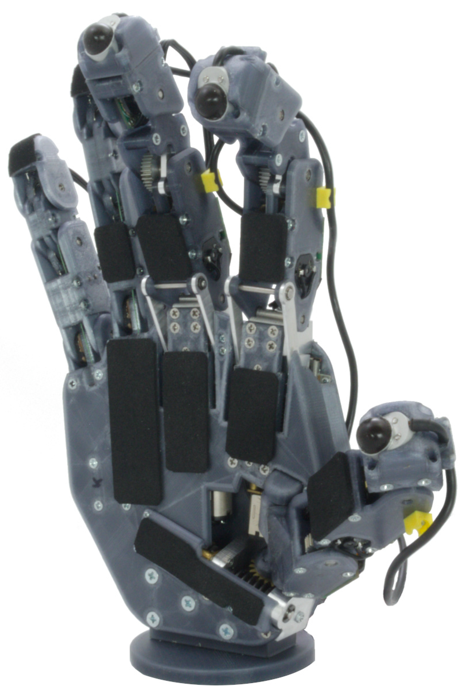
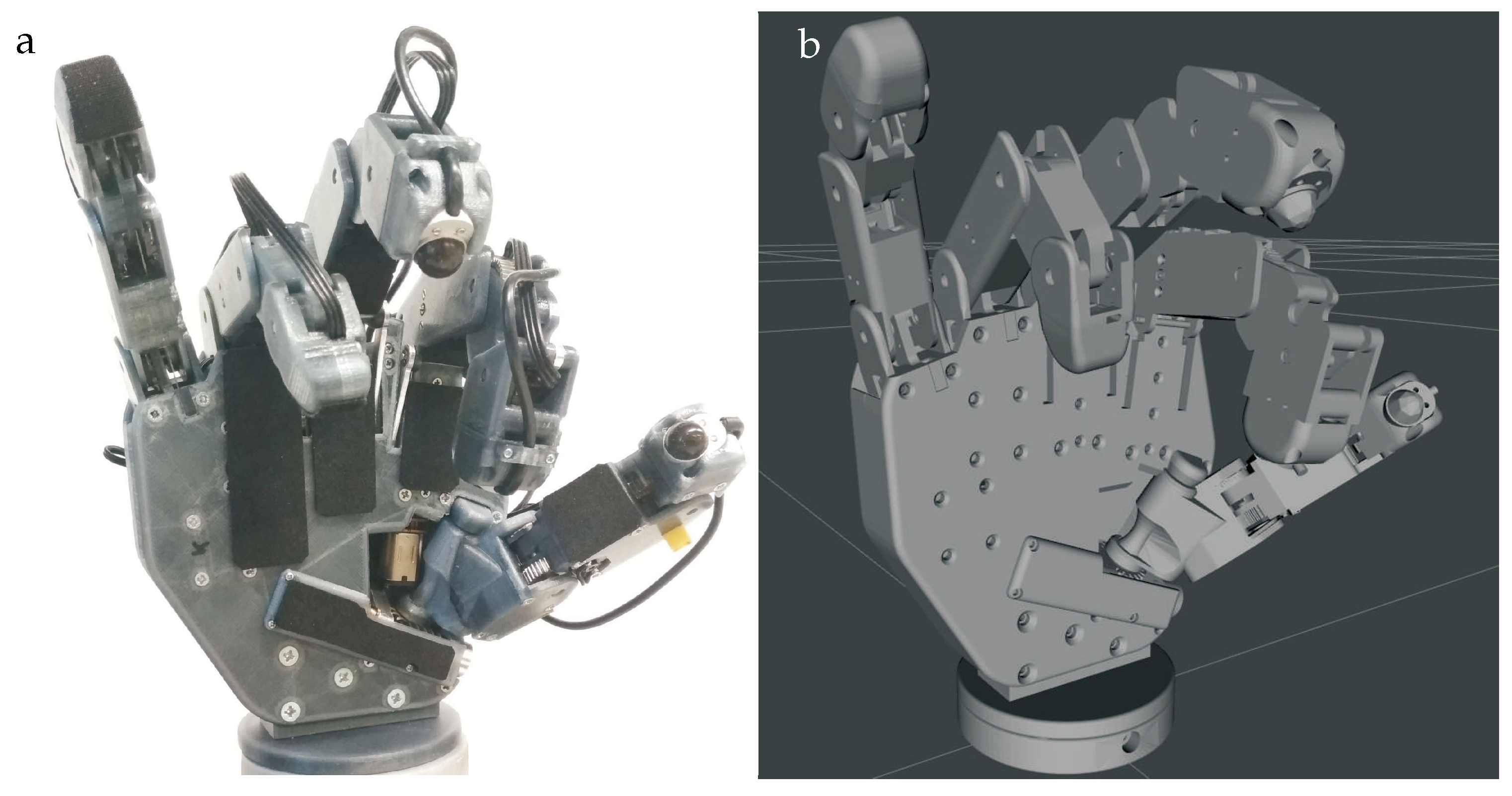
3. PUT-Hand Design
3.1. Mechanical Design
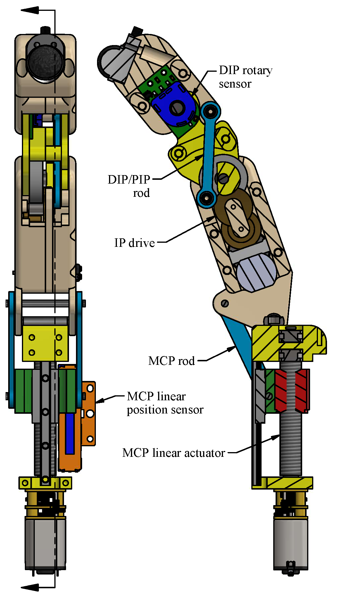
3.1.1. Fully Actuated Fingers (Index and Middle)
3.1.2. Thumb
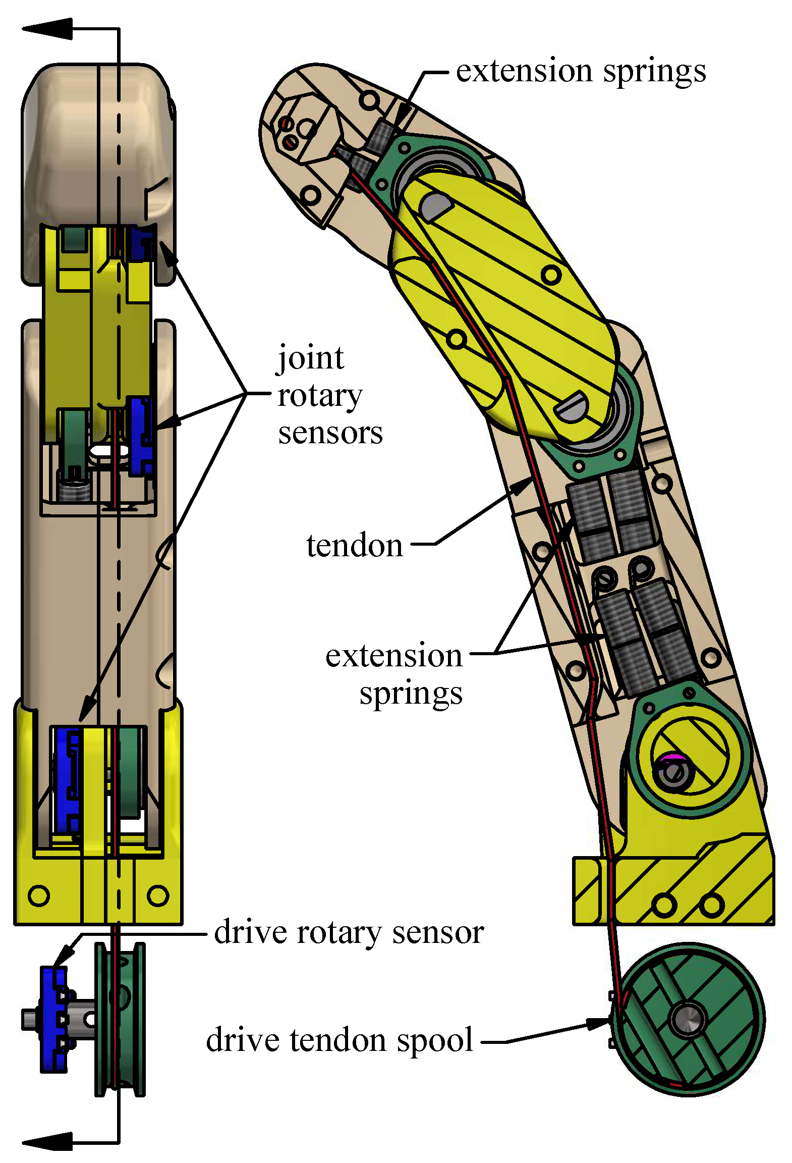
3.1.3. Underactuated Finger
3.2. Controller
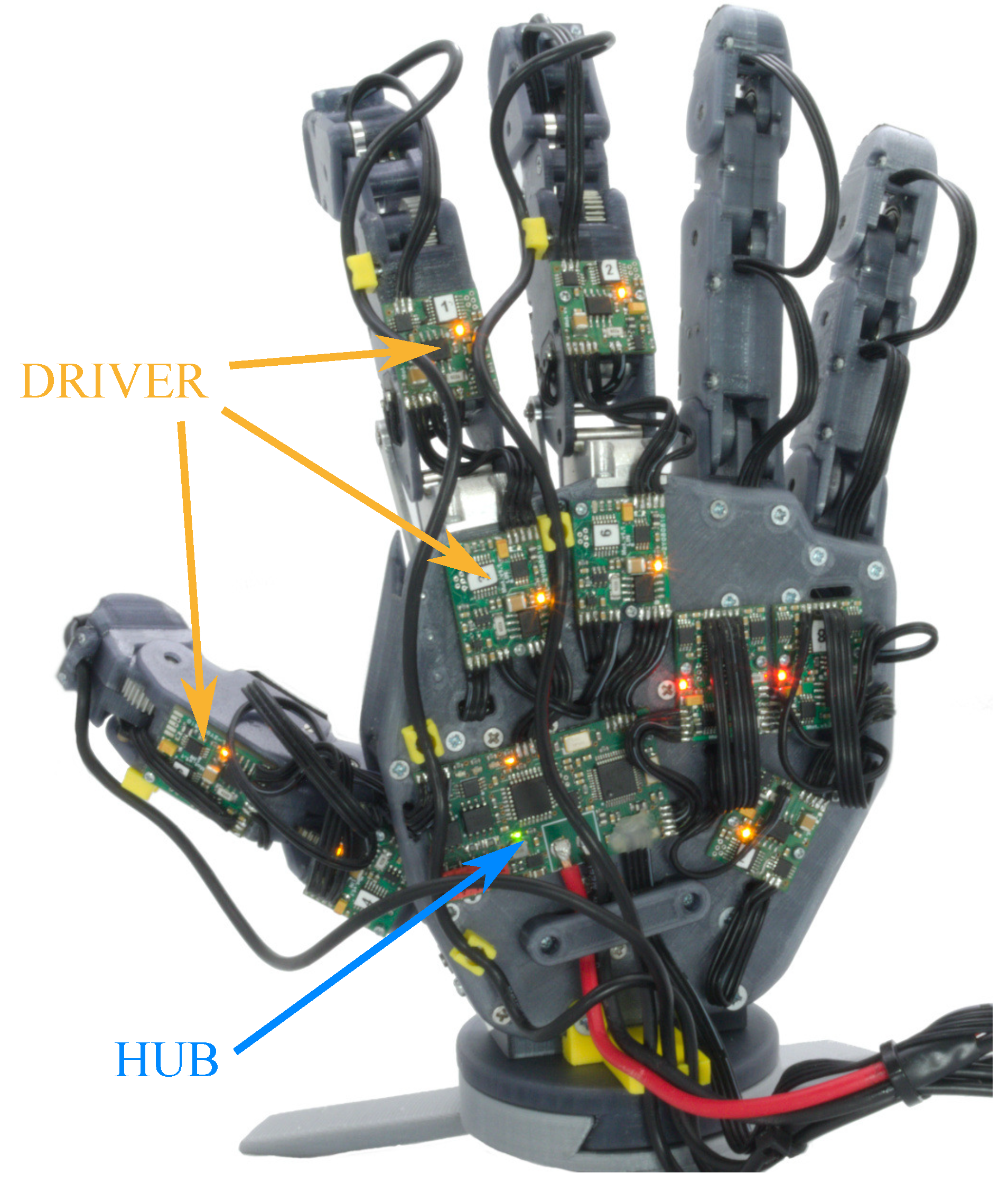
3.2.1. HUB Design
3.2.2. DRIVER Design
3.3. Firmware
- Idle—where all DRIVERs engage electronic brake or disable the H-bridge, depending on user’s choice.
- Internal—where HUB’s internal PID controller with dead-zone is used to position fingers. In this mode, user sets a desired fingers position via the USB interface. Internal PID does not provide force regulation, motor currents are neglected. A diagram of internal control mode is presented in Figure 12a.
- External—in this mode HUB acts as a middleman between external user implemented controller and particular drives, providing information about DRIVERs status and forwarding PWM duty. A diagram of external control mode is presented in Figure 12b.
3.4. Kinematic Model of PUT-Hand
3.5. High-Level Controller
4. Results
4.1. Grasping
4.2. Elastic Object Insertion
4.3. Contact Force Measurements
4.3.1. In-Hand Elastic Object Identification
4.3.2. Plug Insertion
5. Conclusions and Further Development
- open-source mechanical design of PUT-Hand, a hybrid anthropomorphic gripper design consisting of three fully actuated fingers (thumb, index, and middle) for precise manipulation, and two underactuated tendon-driven digits (ring and small) for power-grasp support;
- open-source on-board controller design and firmware;
- sensory system using optical 3-axis force sensors;
- ROS-based open-source driver for high-level control including motion planning and visualisation;
- experimental verification presenting mechanical and sensory capabilities of the proposed design.
Author Contributions
Funding
Conflicts of Interest
Abbreviations
| DIP | Distant Interphalangeal joint |
| MCP | Metacarpophalangeal joint |
| IP | Interphalangeal joint |
| ROS | Robot Operating System |
| DoF | Degree of Freedom |
| URDF | Universal Robot Description Format |
References
- Schunk. Servo-Electric 3-Finger Gripping Hand (SDH). Available online: http://www.schunk-modular-robotics.com (accessed on 18 June 2019).
- Zollo, L.; Roccella, S.; Guglielmelli, E.; Carrozza, M.; Dario, P. Biomechatronic Design and Control of an Anthropomorphic Artificial Hand for Prosthetic and Robotic Applications. IEEE/ASME Trans. Mechatron. 2007, 12, 418–429. [Google Scholar] [CrossRef]
- Massa, B.; Roccella, S.; Carrozza, M.; Dario, P. Design and development of an underactuated prosthetic hand. In Proceedings of the 2002 IEEE International Conference on Robotics and Automation (Cat. No.02CH37292), Washington, DC, USA, 11–15 May 2002; pp. 3374–3379. [Google Scholar]
- VINCENTevolution 2 Prosthetic Hand. Available online: http://vincentsystems.de/en/prosthetics/ (accessed on 18 June 2019).
- Liu, H.; Wu, K.; Meusel, P.; Seitz, N.; Hirzinger, G.; Jin, M.; Liu, Y.; Fan, S.; Lan, T.; Chen, Z. Multisensory five-finger dexterous hand: The DLR/HIT Hand II. In Proceedings of the 2008 IEEE/RSJ International Conference on Intelligent Robots and Systems, Nice, France, 22–26 September 2008; pp. 3692–3697. [Google Scholar]
- Aukes, D.; Heyneman, B.; Ulmen, J.; Stuart, H.; Cutkosky, M.; Kim, S.; Garcia, P.; Edsinger, A. Design and testing of a selectively compliant underactuated hand. Int. Robot. Res. 2014, 33, 721–735. [Google Scholar] [CrossRef]
- iLimb Prosthetic Hands. Available online: http://www.touchbionics.com/products (accessed on 18 June 2019).
- Michelangelo Prosthetic Hand. Available online: https://www.ottobockus.com/prosthetics/upper-limb-prosthetics/ (accessed on 18 June 2019).
- Jacobsen, S.; Iversen, E.; Knutti, D.; Johnson, R.; Biggers, K. Design of the Utah/M.I.T. Dextrous Hand. In Proceedings of the 1986 IEEE International Conference on Robotics and Automation, San Francisco, CA, USA, 7–10 April 1986; Volume 3, pp. 1520–1532. [Google Scholar]
- Martin, J.; Grossard, M. Design of a fully modular and backdrivable dexterous hand. Int. Robot. Res. 2014, 33, 783–798. [Google Scholar] [CrossRef]
- Quigley, M.; Salisbury, C.; Ng, A.; Salisbury, J. Mechatronic design of an integrated robotic hand. Int. Robot. Res. 2014, 33, 706–720. [Google Scholar] [CrossRef]
- Rothling, F.; Haschke, R.; Steil, J.; Ritter, H. Platform portable anthropomorphic grasping with the bielefeld 20-DOF shadow and 9-DOF TUM hand. In Proceedings of the 2007 IEEE/RSJ International Conference on Intelligent Robots and Systems, San Diego, CA, USA, 29 October–2 November 2007; pp. 2951–2956. [Google Scholar]
- Su, Y.; Wu, Y.; Lee, K.; Du, Z.; Demiris, Y. Robust grasping for an under-actuated anthropomorphic hand under object position uncertainty. In Proceedings of the 2012 12th IEEE-RAS International Conference on Humanoid Robots (Humanoids 2012), Osaka, Japan, 29 November–1 December 2012; pp. 719–725. [Google Scholar]
- Tomovic, R.; Boni, G. An adaptive artificial hand. IRE Trans. Autom. Control 1962, 7, 3–10. [Google Scholar] [CrossRef]
- Treratanakulwong, T.; Kaminaga, H.; Nakamura, Y. Low-friction tendon-driven robot hand with carpal tunnel mechanism in the palm by optimal 3D allocation of pulleys. In Proceedings of the 2014 IEEE International Conference on Robotics and Automation (ICRA), Hong Kong, China, 31 May–7 June 2014; pp. 6739–6744. [Google Scholar]
- Pons, J.; Rocon, E.; Ceres, R.; Reynaerts, D.; Saro, B.; Levin, S.; Van Moorleghem, W. The MANUS-HAND Dextrous Robotics Upper Limb Prosthesis: Mechanical and Manipulation Aspects. Auton. Robot. 2004, 16, 143–163. [Google Scholar] [CrossRef]
- Lotti, F.; Tiezzi, P.; Vassura, G.; Biagiotti, L.; Palli, G.; Melchiorri, C. Development of UB Hand 3: Early Results. In Proceedings of the 2005 IEEE International Conference on Robotics and Automation, Barcelona, Spain, 18–22 April 2005; pp. 4488–4493. [Google Scholar]
- Controzzi, M.; Cipriani, C.; Carrozza, C. Mechatronic Design of a Transradial Cybernetic Hand. In Proceedings of the 2008 IEEE/RSJ International Conference on Intelligent Robots and Systems, Nice, France, 22–26 September 2008; pp. 576–581. [Google Scholar]
- Cipriani, C.; Controzzi, M.; Carrozza, M. Objectives, criteria and methods for the design of the SmartHand transradial prosthesis. Robotica 2010, 28, 919–927. [Google Scholar] [CrossRef] [Green Version]
- Kamikawa, Y.; Maeno, T. Underactuated five-finger prosthetic hand inspired by grasping force distribution of humans. In Proceedings of the 2008 IEEE/RSJ International Conference on Intelligent Robots and Systems, IROS, Nice, France, 22–26 September 2008; pp. 717–722. [Google Scholar]
- Dalley, S.; Wiste, T.; Withrow, T.; Goldfarb, M. Design of a Multifunctional Anthropomorphic Prosthetic Hand With Extrinsic Actuation. IEEE/ASME Trans. Mechatron. 2009, 14, 699–706. [Google Scholar] [CrossRef]
- Xu, Z.; Kumar, V.; Todorov, E. A Low-cost and Modular, 20-DOF Anthropomorphic Robotic Hand: Design, Actuation and Modeling. In Proceedings of the 2013 13th IEEE-RAS International Conference on Humanoid Robots (Humanoids), Atlanta, GA, USA, 15–17 October 2013; pp. 368–375. [Google Scholar]
- Xu, Z.; Todorov, E. Design of a highly biomimetic anthropomorphic robotic hand towards artificial limb regeneration. In Proceedings of the 2016 IEEE International Conference on Robotics and Automation (ICRA), Stockholm, Sweden, 16–21 May 2016; pp. 3485–3492. [Google Scholar]
- Santina, C.; Grioli, G.; Catalano, M.; Brando, A.; Bicchi, A. Dexterity augmentation on a synergistic hand: The Pisa/IIT SoftHand+. In Proceedings of the 2015 IEEE-RAS 15th International Conference on Humanoid Robots (Humanoids), Seoul, Korea, 3–5 November 2015; pp. 497–503. [Google Scholar]
- Ma, R.R.; Odhner, L.U.; Dollar, A.M. A modular, open-source 3D printed underactuated hand. In Proceedings of the 2013 IEEE International Conference on Robotics and Automation, Karlsruhe, Germany, 6–10 May 2013; pp. 2737–2743. [Google Scholar]
- Salvietti, G.; Hussain, I.; Malvezzi, M.; Prattichizzo, D. Design of the Passive Joints of Underactuated Modular Soft Hands for Fingertip Trajectory Tracking. IEEE Robot. Autom. Lett. 2017, 2, 2008–2015. [Google Scholar] [CrossRef] [Green Version]
- Mianowski, K.; Berns, K.; Hirth, J. The artificial hand with elastic fingers for humanoid robot ROMAN. In Proceedings of the 2013 18th International Conference on Methods & Models in Automation & Robotics (MMAR), Miedzyzdroje, Poland, 26–29 August 2013; pp. 448–453. [Google Scholar]
- Dechev, N.; Cleghorn, W.; Naumann, S. Multiple Finger, passive adaptive grasp prosthetic hand. Mech. Mach. Theory 2001, 36, 1157–1173. [Google Scholar] [CrossRef]
- Light, C.; Chappel, P. Development of a lightweight and adaptable multiple-axis hand prosthesis. Med. Eng. Phys. 2000, 22, 679–684. [Google Scholar] [CrossRef]
- Deimel, R.; Brock, O. A Novel Type of Compliant, Underactuated Robotic Hand for Dexterous Grasping. Proc. Robot. Sci. Syst. 2014, 35, 161–185. [Google Scholar]
- Gaiser, I.; Pylatiuk, C.; Schulz, S.; Kargov, A.; Oberle, R.; Werner, T. The FLUIDHAND III: A Multifunctional Prosthetic Hand. JPO J. Prosthetics Orthot. 2009, 21, 91–96. [Google Scholar] [CrossRef]
- Schunk, Servo-Electric 5-Finger Gripping Hand (SVH). Available online: http://www.schunk-modular-robotics.com (accessed on 18 June 2019).
- Losier, Y.; Clawson, A.; Wilson, A.; Scheme, E.; Englehart, K.; Kyberd, P.; Hudgins, B. An Overview of the UNB Hand System. In Proceedings of the MyoElectric Controls/Powered Prosthetics, Fredericton, NB, Canada, 14–19 August 2011; pp. 1–4. [Google Scholar]
- You, W.S.; Lee, Y.H.; Oh, H.S.; Kang, G.; Choi, H.R. Design of a 3D-printable, robust anthropomorphic robot hand including intermetacarpal joints. Intell. Serv. Robot. 2019, 12, 1–16. [Google Scholar] [CrossRef]
- Yang, H.; Wei, G.; Ren, L. Design and Development of a Linkage-Tendon Hybrid Driven Anthropomorphic Robotic Hand. In Intelligent Robotics and Applications; Yu, H., Liu, J., Liu, L., Ju, Z., Liu, Y., Zhou, D., Eds.; Springer International Publishing: Cham, Switzerland, 2019; pp. 117–128. [Google Scholar]
- Mizushima, K.; Oku, T.; Suzuki, Y.; Tsuji, T.; Watanabe, T. Multi-fingered robotic hand based on hybrid mechanism of tendon-driven and jamming transition. In Proceedings of the 2018 IEEE International Conference on Soft Robotics (RoboSoft), Livorno, Italy, 24–28 April 2018; pp. 376–381. [Google Scholar]
- Yazici, M.V.; Kahveci, A.; Kiziltaş, F.S.; Mülayim, N.; Gezgin, E. Design and Development of a Surgical Robotic Hand with Hybrid Structure. In Proceedings of the 2018 Medical Technologies National Congress (TIPTEKNO), Magusa, Cyprus, 8–10 November 2018; pp. 1–4. [Google Scholar]
- Mahanta, G.B.; Rout, A.; Deepak, B.B.V.L.; Biswal, B.B.; Gunji, B.M. Preliminary Design and Fabrication of Bio-Inspired Low-Cost Hybrid Soft-Rigid Robotic Hand for Grasping Delicate Objects. In Proceedings of the 2019 9th Annual Information Technology, Electromechanical Engineering and Microelectronics Conference (IEMECON), Jaipur, India, 13–15 March 2019; pp. 17–23. [Google Scholar]
- Jeong, H.; Cheong, J. Design of hybrid type robotic hand: The KU hybrid HAND. In Proceedings of the 2011 11th International Conference on Control, Automation and Systems, Gyeonggi-do, Korea, 26–29 October 2011; pp. 1113–1116. [Google Scholar]
- Jeong, H.; Cheong, J. Design and analysis of KU hybrid hand—Type II. In Proceedings of the 2013 10th International Conference on Ubiquitous Robots and Ambient Intelligence (URAI), Jeju, Korea, 30 October–2 November 2013; pp. 580–583. [Google Scholar]
- Cerruti, G.; Chablat, D.; Gouaillier, D.; Sakka, S. ALPHA: A hybrid self-adaptable hand for a social humanoid robot. In Proceedings of the 2016 IEEE/RSJ International Conference on Intelligent Robots and Systems (IROS), Daejeon, Korea, 9–14 October 2016; pp. 900–906. [Google Scholar]
- Townsend, W. The BarrettHand grasper—programmably flexible part handling and assembly. Ind. Robot. 2000, 27, 181–188. [Google Scholar] [CrossRef] [Green Version]
- Aukes, D.; Cutkosky, M. Simulation-based tools for evaluating underactuated hand designs. In Proceedings of the 2013 IEEE International Conference on Robotics and Automation, Karlsruhe, Germany, 6–10 May 2013; pp. 2067–2073. [Google Scholar]
- Grioli, G.; Catalano, M.; Silvestro, E.; Tono, S.; Bicchi, A. Adaptive synergies: An approach to the design of under-actuated robotic hands. In Proceedings of the 2008 IEEE/RSJ International Conference on Intelligent Robots and Systems, IROS, Vilamoura, Portugal, 7–12 October 2012; pp. 1251–1256. [Google Scholar]
- Xu, K.; Liu, H. Continuum Differential Mechanisms and Their Applications in Gripper Designs. IEEE Trans. Robot. 2016, 32, 754–762. [Google Scholar] [CrossRef]
- Tomczyński, J.; Mańkowski, T.; Walas, K.; Kaczmarek, P. CIE-Hand towards Prosthetic Limb. In Progress in Automation, Robotics and Measuring Techniques; Szewczyk, R., Zieliński, C., Kaliczyńska, M., Eds.; Springer International Publishing: Cham, Switzerland, 2015; pp. 275–284. [Google Scholar]
- Kopicki, M.; Detry, R.; Adjigble, M.; Stolkin, R.; Leonardis, A.; Wyatt, J.L. One-shot learning and generation of dexterous grasps for novel objects. Int. J. Robot. Res. 2015, 35, 959–976. [Google Scholar] [CrossRef]
- Kopicki, M.; Belter, D.; Wyatt, J.L. Learning better generative models for dexterous, single-view grasping of novel objects. Int. J. Robot. Res. 2019. [Google Scholar] [CrossRef] [Green Version]
- Arruda, E.; Wyatt, J.; Kopicki, M. Active vision for dexterous grasping of novel objects. In Proceedings of the 2016 IEEE/RSJ International Conference on Intelligent Robots and Systems (IROS), Daejeon, Korea, 9–14 October 2016; pp. 2881–2888. [Google Scholar]
- Grebenstein, G.; Suchi, M.; Kampel, M.; Vincze, M. An Empirical Evaluation of Ten Depth Cameras: Bias, Precision, Lateral Noise, Different Lighting Conditions and Materials, and Multiple Sensor Setups in Indoor Environments. IEEE Robot. Autom. Mag. 2019, 26, 67–77. [Google Scholar]
- Tian, S.; Ebert, F.; Jayaraman, D.; Mudigonda, M.; Finn, C.; Calandra, R.; Levine, S. Manipulation by Feel: Touch-Based Control with Deep Predictive Models. In Proceedings of the IEEE International Conference on Robotics and Automation, Montreal, QC, Canada, 20–24 May 2019; pp. 818–824. [Google Scholar]
- Hsiao, K.; Chitta, S.; Ciocarlie, M.T.; Jones, E.G. Contact-reactive grasping of objects with partial shape information. In Proceedings of the 2010 IEEE/RSJ International Conference on Intelligent Robots and Systems, Taipei, Taiwan, 18–22 October 2010; pp. 1228–1235. [Google Scholar]
- Lin, J.; Calandra, R.; Levine, S. Learning to Identify Object Instances by Touch: Tactile Recognition via Multimodal Matching. In Proceedings of the IEEE International Conference on Robotics and Automation, Montreal, QC, Canada, 20–24 May 2019; pp. 3644–3650. [Google Scholar]
- Hyttinen, E.; Kragic, D.; Detry, R. Learning the tactile signatures of prototypical object parts for robust part-based grasping of novel objects. In Proceedings of the IEEE International Conference on Robotics and Automation, Seattle, WA, USA, 26–30 May 2015; pp. 4927–4932. [Google Scholar]
- Tomo, T.P.; Schmitz, A.; Wong, W.K.; Kristanto, H.; Somlor, S.; Hwang, J.; Jamone, L.; Sugano, S. Covering a robot fingertip with uskin: A soft electronic skin with distributed 3-axis force sensitive elements for robot hands. IEEE Robot. Autom. Lett. 2018, 2, 124–131. [Google Scholar] [CrossRef]
- Funabashi, S.; Yan, G.; Geier, A.; Schmitz, A.; Ogata, T.; Sugano, S. Morphology-Specific Convolutional Neural Networks for Tactile Object Recognition with a Multi-Fingered Hand. In Proceedings of the IEEE International Conference on Robotics and Automation, Montreal, QC, Canada, 20–24 May 2019; pp. 57–63. [Google Scholar]
- Blanes, C.; Mellado, M.; Beltrán, P. Tactile sensing with accelerometers in prehensile grippers for robots. Mechatronics 2016, 33, 1–12. [Google Scholar] [CrossRef]
- Seminara, L.; Pinna, L.; Ibrahim, A.; Noli, L.; Caviglia, S.; Gastaldo, P.; Valle, M. Towards integrating intelligence in electronic skin. Mechatronics 2016, 34, 84–94. [Google Scholar] [CrossRef]
- Dargahi, J.; Sedaghati, R.; Singh, H.; Najarian, S. Modeling and testing of an endoscopic piezoelectric-based tactile sensor. Mechatronics 2007, 17, 462–467. [Google Scholar] [CrossRef]
- Pan, Z.; Zhu, Z. Flexible full-body tactile sensor of low cost and minimal output connections for service robot. Mechatronics 2005, 32, 485–491. [Google Scholar] [CrossRef]
- Hristu, D.; Ferrier, N.; Brockett, R.W. The performance of a deformable-membrane tactile sensor: Basic results on geometrically-defined tasks. In Proceedings of the IEEE International Conference on Robotics and Automation, San Francisco, CA, USA, 24–28 April 2000; pp. 508–513. [Google Scholar]
- Hashizume, J.; Tae Myung, H.; Suresh, S.A.; Cutkosky, M.R. Capacitive Sensing for a Gripper with Gecko-Inspired Adhesive Film. IEEE Robot. Autom. Lett. 2019, 4, 677–683. [Google Scholar] [CrossRef]
- Fearing, R. Tactile sensing mechanisms. Int. J. Robot. Res. 1990, 9, 3–23. [Google Scholar] [CrossRef]
- Luo, S.; Bimbo, J.; Dahiya, R.; Liua, H. Robotic tactile perception of object properties: A review. Mechatronics 2017, 48, 54–67. [Google Scholar] [CrossRef] [Green Version]
- Wettels, N.; Fishel, J.; Loeb, G. Multimodal Tactile Sensor. In The Human Hand as an Inspiration for Robot Hand Development, Springer Tracts in Advanced Robotics; Ramachandran Balasubramanian, S.V., Ed.; Springer: Cham, Switzerland, 2016; pp. 405–429. [Google Scholar]
- Feix, T.; Romero, J.; Schmiedmayer, H.; Dollar, A.M.; Kragic, D. The GRASP Taxonomy of Human Grasp Types. IEEE Trans. Hum. Mach. Syst. 2016, 46, 66–77. [Google Scholar] [CrossRef]
- Johnson, P.W.; Blackstone, J.M. Children and gender-differences in Exposure and How Anthropometric Differences Can be Incorporated into the Design of Computer Input Devices. Scand. J. Work. Environ. Health 2007, 26, 26–32. [Google Scholar]
- Scalera, L.; Palomba, I.; Wehrle, E.; Gasparetto, A.; Vidoni, R. Natural Motion for Energy Saving in Robotic and Mechatronic Systems. Appl. Sci. 2019, 9, 3516. [Google Scholar] [CrossRef] [Green Version]
- Coleman, D.; Sucan, I.; Chitta, S.; Correll, N. Reducing the Barrier to Entry of Complex Robotic Software: A MoveIt! Case-Study. J. Softw. Eng. Robot. 2014, 5, 3–16. [Google Scholar]


| Tendon mechanism | [2,3,6,9,10,11,12,13,14,15,16,17,18,19,20,21,22,23,24,25,26] |
| Gears | [1,5] |
| Rod-based | [27] |
| Rigid linkage system | [28,29] |
| Differential drivetrain | [17] |
| Pneumatic chamber | [30] |
| Hydraulic muscles | [31] |
| Fully actuated | [1,9,11,22,31,32] |
| Underactuated | [2,3,6,14,15,16,18,19,20,21,23,24,25,27,28,29,30,33] |
| Hybrid designs | [34,35,36,37,38,39,40,41] |
| Three-fingered | [1,2,3] |
| Four-fingered | [6,9,11,25,34,39,40] |
| Five-fingered | [5,10,12,13,14,15,16,17,18,19,20,21,22,23,24,27,28,29,30,31,32,35,35] |
| Joint | Max | Min |
|---|---|---|
| / | ||
| / | ||
| / | ||
| / | ||
| / | ||
| / |
© 2020 by the authors. Licensee MDPI, Basel, Switzerland. This article is an open access article distributed under the terms and conditions of the Creative Commons Attribution (CC BY) license (http://creativecommons.org/licenses/by/4.0/).
Share and Cite
Mańkowski, T.; Tomczyński, J.; Walas, K.; Belter, D. PUT-Hand—Hybrid Industrial and Biomimetic Gripper for Elastic Object Manipulation. Electronics 2020, 9, 1147. https://doi.org/10.3390/electronics9071147
Mańkowski T, Tomczyński J, Walas K, Belter D. PUT-Hand—Hybrid Industrial and Biomimetic Gripper for Elastic Object Manipulation. Electronics. 2020; 9(7):1147. https://doi.org/10.3390/electronics9071147
Chicago/Turabian StyleMańkowski, Tomasz, Jakub Tomczyński, Krzysztof Walas, and Dominik Belter. 2020. "PUT-Hand—Hybrid Industrial and Biomimetic Gripper for Elastic Object Manipulation" Electronics 9, no. 7: 1147. https://doi.org/10.3390/electronics9071147
APA StyleMańkowski, T., Tomczyński, J., Walas, K., & Belter, D. (2020). PUT-Hand—Hybrid Industrial and Biomimetic Gripper for Elastic Object Manipulation. Electronics, 9(7), 1147. https://doi.org/10.3390/electronics9071147