Article

Large Dynamic Current Monitoring for UAV Steering Motor Using Twin Nonlinear Shunt

1
School of Computer Science, Northwestern Polytechnical University, Xi’an 714300, China
2
School of Communication and Information Engineering, Xi’an University of Posts and Telecommunications, Xi’an 710121, China
*
Author to whom correspondence should be addressed.
Electronics 2020, 9(8), 1240; https://doi.org/10.3390/electronics9081240
Submission received: 14 July 2020 / Revised: 24 July 2020 / Accepted: 30 July 2020 / Published: 1 August 2020
(This article belongs to the Section Industrial Electronics)

Abstract

:
Steering motor is of vital importance in UAV’s health-monitoring system, to which its supply current is the most critical characteristic representing health statue of UAV. In order to conduct continuous measuring on the steering motor’s current of large dynamic range, in this paper, a current measurement method is therefore proposed on the basis of twin nonlinear shunt. The proposed method adopts the twin diode as the current sampling device, which not only realizes measurement range and relative constant resolution, but also ensures continuity of the measurement due to the eliminated operation of range switching. The associated diode is used to compensate the temperature of core temperature of the shunt diode, and to make the nonlinear-shunt more adaptive for the case of junction being heated under larger current. The working principle, real-time compensation method and circuit implementation of our method are discussed in detail. Experimental test results suggest that the measurement error of the proposed method is less than 4.5% when the measurement current varies between 10 mA to 10 A, maintaining the relative resolution at an almost constant level, while preventing the conventional method of frequent range switching from generating glitches. In addition to the ensured continuity, information-rich details of the current are sustained, contributing to the UAV’s health-monitoring system. The proposal can also be applied to other applications concerning large dynamic current detection, including, but not limited to, industrial control, motor control, etc.

1. Introduction

Intelligentization and autonomy are the evolution trend in the future of the UAV industry; its electrical system develops complicatedly and quantitatively [1]. The implementation of self-diagnosis and intelligent decision highly depends on the health-monitoring of sophisticated components [2]. Results of health monitoring offer a comprehensive evaluation of the UAV’s operation status, which not only facilitates the fault diagnosis and prediction of the potential hazards, but also helps performance degradation analysis and life prediction for critical equipment [3]. The supply current of the equipment being monitored reflects the internal status and burdens during operating. They are regarded as vital physical parameters required by health monitoring, and can be easily obtained through general measurement.
The supply current consists of the total power consumption of all the components included in the monitored equipment. The featuring information that characterizes potential hazards is often concealed in details of current change. Therefore, the current measurement must guarantee two essential factors in terms of the large range and resolution of details. Moreover, the entire measurement process must be continuous, avoiding any circuit switching [4]. Taking the steering motor as an example, it is the most critical actuator for UAV attitude control which is a compound structure of mechanical electrical parts, being under frequent regulation and dynamic load. Hence, the steering motor becomes a prioritized object to be monitored, due to its high fault probability. Abundant information on working status can be extracted from the supply current, involving the circuit status of driving controller, the mechanical state of motor and the rotation transmission system, as well as the pressure and torque of rudder surface during flight. In addition, the characterization of faults or hidden hazards can also be extracted from current ripples.
The value of the supply current of the steering motor varies in large range. When a UAV is in no-load state on the ground, only the control module is active in the steering system; the supply current decreases to dozens of milliampere level. Meanwhile, the peak value of current may rise up to tens of amperes if the motor is jammed or the gear is stuck. During flight, the supply current of steering motor is proportional to the burden on the rudder surface. With constant adjustment of the rudder angle, the varying of the motor’s load causes a rapid change of current up to several amperes. Specifically, when the UAV performs highly maneuverable operations such as climbing, nosedive and hovering, the rudder torque changes rapidly. In this case, the profile of supply current reflects the force and burden of the mechanical part, whereas the detailed current ripple may implicate some forewarnings of mechanical wear and control instability. To sum up, obtaining the supply current of steering motor in large range while remaining its identifiable details is indispensable for subsequent steps in health-monitoring, flight evaluation and life estimation.
In reality, the commonly used method of expanding dynamic range of current measurement being adopted in laboratories and by general instruments may be inappropriate for noisy electromagnetic environment in flight.
In general, the current measuring circuit consists of three parts: a shunt resistor that converts current to voltage, a precision amplifier, and a quantizer that often adopts an analog-to-digital converter (ADC). For general instruments, there are commonly three kinds of method to extend the dynamic range of the measurement. Among them, one is to use high-resolution ADC for quantization, which is expected to improve resolution of the small value with a unique range [5,6]. Another method is to switch the gain of amplifier to achieve multiple ranges, forming the expected capabilities in larger dynamic measurement [7]. However, in real flight electrical systems, small shunt voltage may be submerged by the strong and unavoidable interference of noises. None of the methods can be adopted because the signal-to-noise ratio (SNR) of original shunt voltage is not substantially improved. Recently, certain advanced promising methods have also emerged [8,9,10], for example, adopting a series of multiple shunts while introducing the automatic bypass mechanism to realize the seamless switching of measurement range under the condition of multiple measuring circuits working simultaneously.
The third one is to expand the range by switching shunt resistor [11,12]. Under the circumstances of small current, the shunt resistor is switched into a larger one, which improves the SNR of the original shunt signal, thus avoiding the intricacies of being submerged. Nevertheless, after switching action, subsequent measurement circuit will undergo a transient change. For instance, in a typical UAV system, the sampling interval is 5 ms, and the cut-off frequency of anti-aliasing filter is usually 10–30 Hz, so most instruments need an approximate duration of tens to 100 ms for stabilization. The transient process introduces invalid measurement values, which is inapplicable to current sensing for steering motor that requires frequent switching and continuous monitoring.
Adopting a nonlinear component as shunt is an alternative that balances large dynamic range with acceptable SNR in small current. One method commonly known is using diode as shunt; according to its nonlinear current-voltage characteristic, the sensed current can be converted into voltage values following logarithmic law, to realize an inherent large dynamic measurement. Meanwhile, the continuity of the measurement process is also ensured because the switching of sampling devices is avoided [13,14,15,16].
However, owing to the significant temperature drift characteristics of diode shunt, it is critical to introduce the temperature compensation mechanism to reduce measurement errors caused by environmental temperature change [17]. Despite the above approaches, this method can only be used in micro current measurement. Only under such circumstances can the external temperature compensation mechanism be accurate, because the temperature rise in diode junction and the body resistance of the diode can be neglected.
Therefore, the above method cannot be directly performed in measuring a large current. One explanation is that the large current to be measured will cause an extra rise in junction temperature, and the real-time temperature inside the diode core is hard to obtain. Another reason is that the voltage drop across body resistance cannot be ignored under the condition of large current. Hence, an additional compensation is also required to correct temperature drift of body resistance.
In this paper, the method of using twin device to perform internal temperature compensation at diode junction is proposed. This proposal enables diode shunt to realize more accurate measurement under large current condition, which is particularly applicable to the continuous monitoring of the large dynamic current of the UAV’s steering motor.
A half bridge diode (HBD) is used as a twin shunt, one branch of which functions as a shunt, and the other performs as referenced in the compensation part. The symmetry exists in the manufacturing processing of the twin diode; sharing the same substrate enables an approximation of junction temperature. Therefore, the parameters obtained from the reference branch can be used to compensate the temperature drift of shunt branch. The errors are induced by temperature rise that is caused by a large current, as well as by the voltage drop on body resistance, and these can be eliminated.
In practical applications, the alternative method exhibits excellent compatibility with a conventional measurement circuit. The adoption of the proposed method can be simply realized by replacing shunt resistor with twin diode. The proposal can also be used in various types of applications for large dynamic range current monitoring.
The remainder of the paper is organized as follows. Section 2 highlights the physical and mathematical rationale in measuring current by using nonlinear twin shunt. Section 3 presents implementation and measuring results of the current-monitoring circuit. Section 4 outlines experimental results with regard to measurement errors. Section 5 summarizes the discussion and conclusions.

2. Principle of Operation

2.1. Consistency Analysis of Twin Diode

In this study, a diode with logarithmic current-voltage characteristics is adopted as current shunt, and a twin diode is used to perform its temperature compensation. In principle, the internal structure of certain integrated rectifiers can be regarded as twin diodes. Taking Schottky half-bridge rectifier as an example, its internal structure is shown in Figure 1. Those two rectifiers share one common substrate and metal heat sink, displaying similar current-voltage and temperature drift characteristics due to the identical manufacturing process.
Table 1 and Table 2 show the measured current-voltage characteristics of the Schottky half-bridge diode (model MUR3020) at two different temperatures. A current ranging from 0.1 A up to 10 A is applied simultaneously in between A1 and K, as well as in between A2 and K, respectively, thereby comparing the voltage between two diodes. The results indicated that, over a wide operating temperature range, only ~1% difference exists in the output voltage of a twin-structured diode that functions as a current sampling device.
In order to investigate thermal coupling characteristics of the twin junction, a thermal simulation analysis of the device was conducted. Simulation model is shown in Figure 2a: diode A1 functions as a shunt, diode A2 performs as a reference device, in which the given current is injected into A1, while A2 remains the unused state. The ambient temperature in the simulation model stays at room temperature, and the twin diode is mounted on a heatsink of 10 cm × 10 cm × 1 cm. The steady-state temperature difference between two junctions was examined under the condition of different given currents flowing through A1.
It can be seen from Figure 2 that the heat generated by the A1 functioning as a shunt caused local temperature rise, yet the difference in junction temperature was small, which can be attributed to the close neighboring of the two diodes. During the normal flight of a UAV with its average current (about 1 A), the temperature difference between two junctions of the twin diode is 0.5 °C, which does not exceed 4 °C even under the limit current (10 A) of lock-rotor protection. Excellent thermal matching characteristics can offer possibilities in using the reference diode for temperature compensation.

2.2. Current Measurement Method Based on Twin Diode

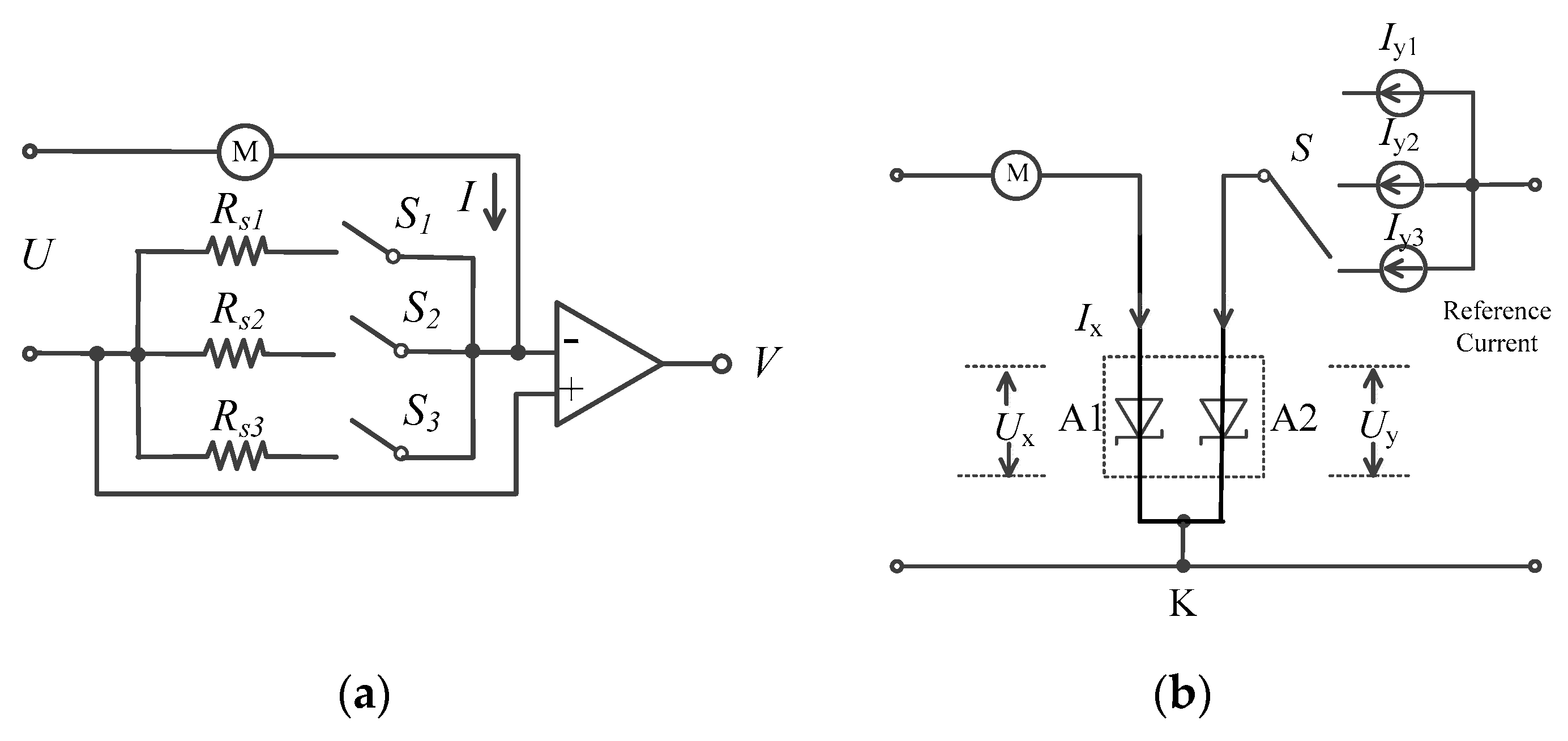
The current measurement method that is based on the twin device is shown in Figure 3, in which A1 is the sampling diode, A2 is the reference diode, Ix is the current to be measured, Iy is the reference current being injected into the reference diode A2, K is the common cathode for A1 and A2.
The measurement consists of two processes that are conducted simultaneously. On one hand, the measured current Ix is sampled by diode A1 to obtain a continuous sampling voltage Ux. Meanwhile, a selectable current Iy with three values is injected into the reference diode A2 (the current is switched in between three values Iy1, Iy2, Iy3); the voltage Uy = [Uy1, Uy2, Uy3] is recorded at both ends of A2. Uy and Iy are used to solve temperature-sensitive parameters in the diode model, and to compensate for the temperature drift characteristics of A1. Finally, the measured current Ix can therefore be calculated by Ux with compensation parameters.
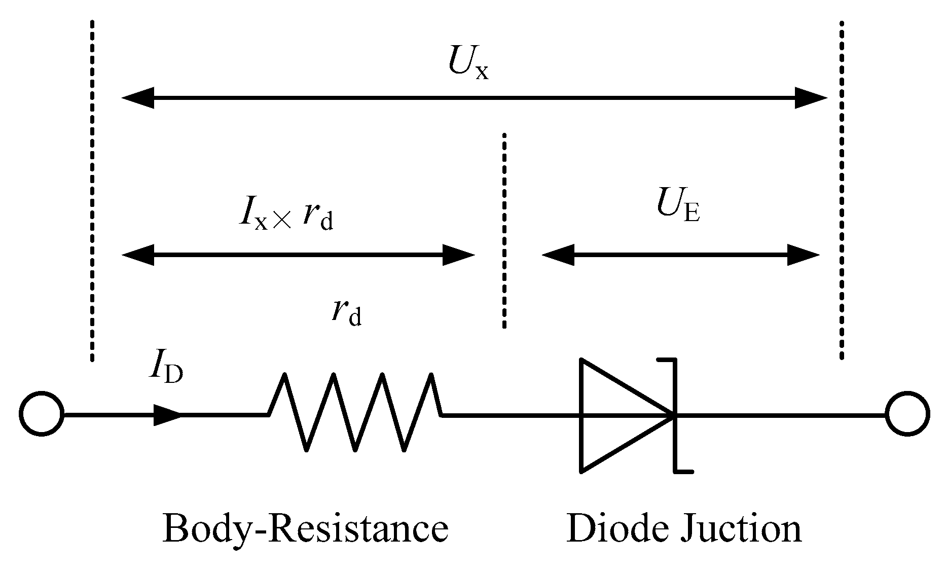
The diode with large current is equivalent to the model in Figure 4, in which Ux is the port voltage of the diode that can be directly measured by circuit, rd is the body-resistance of the diode, and UE represents the junction voltage of the diode. Due to the voltage drop caused by body-resistance rd of the diode, the measured port voltage is given by:
U x = U E + r d × I D ,
where ID represents the current flowing through the diode, the current-voltage characteristic of the diode is given by
I D = I s × ( e U E / U t 1 ) .
Is is the reverse saturation current, Ut is temperature-voltage equivalent. By applying logarithm operation on Equation (2), the junction voltage can therefore be expressed as
U E = U t × ln ( I D I s + 1 ) .
It can be seen that an approximate logarithmic relation exists between the junction voltage UE and the current ID. Hence, using diode as a shunt can realize continuous measuring of the current with large dynamic range, thereby avoiding potential abnormal values that are induced by range switching in conventional methods. Usually, the magnitude order for Is stays in level of nA, hence, the condition of ID/Is >> 1 must be satisfied in measuring the large current. Substitute the simplified Equation (3) into Equation (1),
U x = U t × ln ( I D I S ) + r d × I D .
By solving transcendental Equation (4), the current in the diode is given by
I D = U t × ω [ U x U t ln ( U t I s × r d ) ] / r d .
In Equation (5), ω(x) is Wright omega function, its definition is in References [18,19,20].
It can be seen from Equation (5) that when the values of Ut, Is and rd are determined, the current ID flowing through the diode at present state can be calculated according to the measured Ux. The aforementioned three parameters are heavily temperature dependent. Among them, Ut is thermal equivalent voltage that has linear relation with junction temperature (in Kelvin). The reverse saturation current Is is also heavily temperature dependent, meaning that the value of Is doubles for every 10 K rise of temperature. rd is a nonlinear temperature-dependent parameter whose value correlates with the physical structure of the diode and with the resistivity of the semiconductor. However, it is difficult to obtain the real-time junction temperature due to current-caused temperature rise and wide-range varying of heating power. Hence, it is neither appropriate nor accurate to compensate the drifting of measurement values according to ambient temperatures.
Instead of directly using temperature value for compensation, in this study, we obtain three temperature related parameters, Ut, Is, rd, from the reference junction. Owing to the same manufacturing materials used in twin device, the electrical characteristics and thermal parameters of the two diodes can be regarded as identical. By substituting these parameters into Equation (5), the current ID of the sampling junction can be accurately calculated. Therefore, the proposed method not only avoids direct solving of temperature, but also compensates for all temperature-related factors.
In Figure 3, the voltage Uy of A2 can be measured when the reference diode A2 is injected with reference current Iy. In order to solve the three unknowns, ternary equations need to be established. The known reference current can be injected three times, with different values Iy = (Iy1, Iy2, Iy3) respectively, then the voltage of A2 is measured three times to obtain Uy = (Uy1, Uy2, Uy3). Substituting them into Equation (4) respectively, a set of ternary transcendental equations is established:
{ U y 1 = U t × ln ( I y 1 I S ) + r d × I y 1 U y 2 = U t × ln ( I y 2 I S ) + r d × I y 2 U y 3 = U t × ln ( I y 3 I S ) + r d × I y 3 .
The three parameters Ut, Is, rd can be obtained by solving Equation (6). However, due to analytical solutions, they cannot be obtained directly from transcendental equations; an optimized solving method is therefore adopted, by which a three-dimensional search vector P = (Ut, Is, rd) is established, thereby obtaining voltage estimation vector by substituting P into Equation (4).
{ U y 1 = U t × ln ( I y 1 I S ) + r d × I y 1 U y 2 = U t × ln ( I y 1 I S ) + r d × I y 1 U y 3 = U t × ln ( I y 1 I S ) + r d × I y 1 .
If the estimation vector U = (Uy1, Uy2, Uy3) contained in Equation (7) converges to the measured vector U = (Uy1, Uy2, Uy3) in Equation (6), i.e., if U’→U, the searching vector P can be regarded as an approximate numerical solution of Equation (6), upon which an objective function is established as follows:
E = | U U | 2 = ( U y 1 U y 1 ) 2 + ( U y 2 U y 2 ) 2 + ( U y 3 U y 3 ) 2 .
Therefore, the problem of solving Equation (6) is transformed into constrained optimization, meaning that searching for the optimal searching vector P to minimize objective function E, which can be expressed as:
min E = | U U | 2 s . t . { U tmin < U t < U tmax I smin < I s < I smax r dmin < r d < r dmax
For the above issue, the constraint is the search range of three variables that can be determined by theoretical estimation within a possible temperature range. The problem of three-variable constrained optimization can be solved via one of the following ways which involve gradient descent, Newton and conjugate direction methods. Because temperature is a slow variable, each search result should fall near the last optimal solution, hence, only a local optimal solution is needed, for which reason the gradient descent method is adopted.
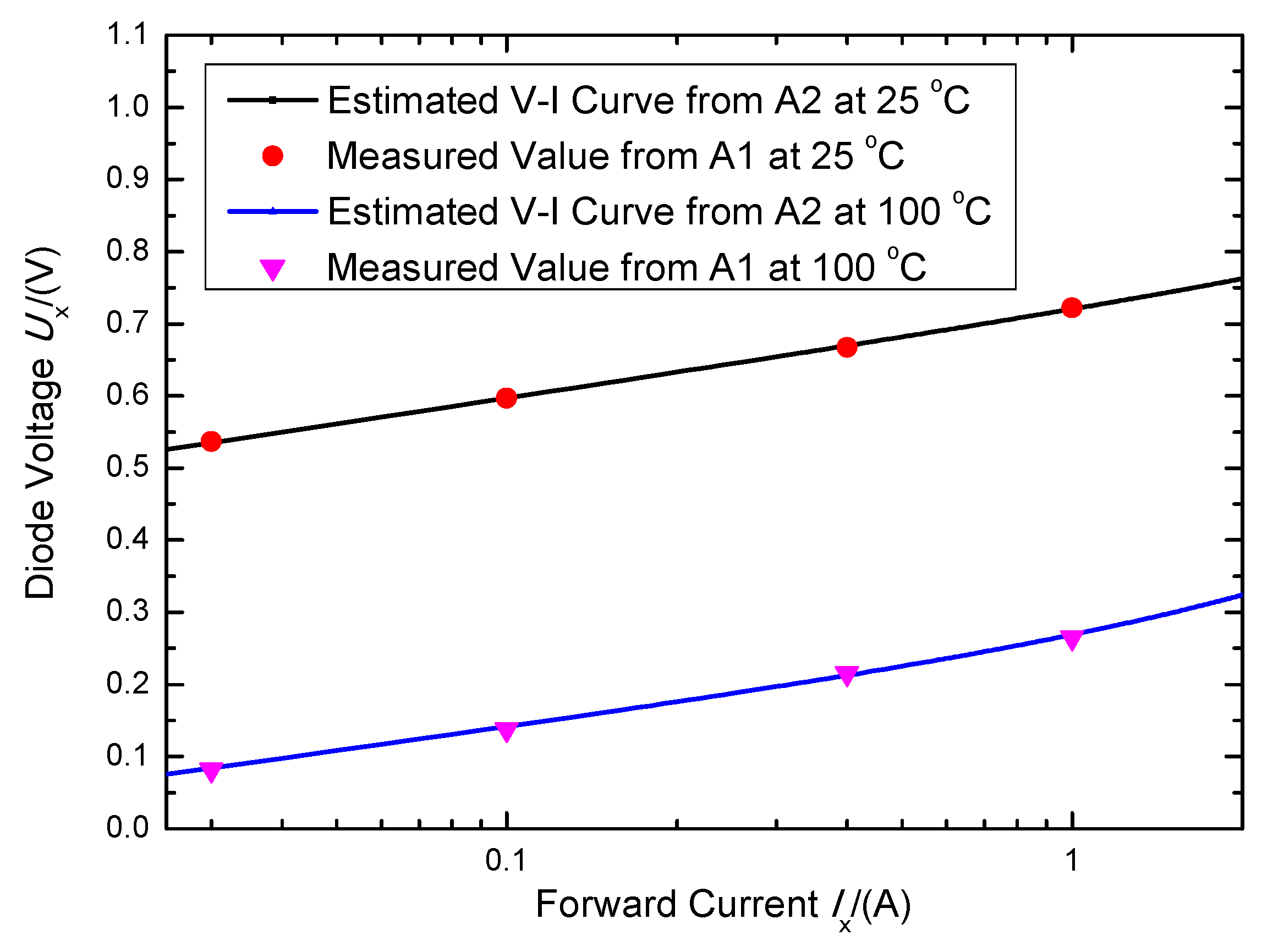
To verify the effectiveness of the proposed method, a Schottky half-bridge device (Model MUR3020) is used. First, different values of the current Iy = (10 mA, 100 mA, 1 A) are injected into the reference diode A2 respectively, then the voltage Uy of A2 can be measured, throughout which Iy injection time is very short, thereby avoiding an additional temperature rise. Second, the optimization process of Equation (9) is performed to calculate thermal parameters P of the diode. The current-voltage curve of the device can be fitted by using Equation (4).
Maintaining same temperature conditions, inject multiple currents to be measured into the sampling diode A1, and the voltage of A1 can be measured. The deviation between the measured data of A1 and the fitting curve is shown in Figure 5. The diode is mounted on a large-sized heat sink, and corresponding experiments are conducted at a junction temperature of 25 °C and 100 °C, respectively. Experimental results indicated that solving thermal parameters to deduce the current of the twin device has proven to be effective.
In this experiment, the current flowing through shunt diode A1 and through reference diode A2 are short-time single pulses, so the junction temperature is mainly determined by ambient temperatures. In practical applications, however, the current flowing through A1 is continuous and changing, causing its junction temperature to vary with the change of the current to be measured. Hence, it is required that the estimation of the thermal parameters of A2 must be accomplished within a time period that is far less than the intrinsic thermal response time of the diode.
Generally, thermal response time depends on the product of thermal resistance and thermal capacity, hence, mounting a larger heat sink with sufficient thermal capacity on the sampling device helps one to extend thermal characteristic time, thereby reducing the speed requirements for optimized search calculation on the reference diode. In the UAV system, the required large thermal capacity can also be achieved through using common mechanical structures such as the shell of airborne devices. Specifically, the time allowed for obtaining the solution of the parameters of the reference device stays no less than a magnitude order of 100 ms, which is much shorter than the sampling interval on the diode A1. Therefore, the computation of the A2 thermal parameters can be assigned as background tasks for the computer, without requiring high real-time performance.

3. Implementation

3.1. Consistency Analysis of Twin Diode

Figure 6a shows conventional current measuring circuit. The voltage across the shunt Rs is amplified and then sampled by subsequent ADC. The measured current value can be calculated according to Equation (10),
I m = U s R s × 1 A ,
where Us is the voltage output, Rs is the resistance value of shunt, and A is the gain of amplifier. In measuring large dynamic current, conventional methods require the manual switching of the shunt Rs or of the amplification gain A to adapt dynamic current ranges, at which moment certain glitches may occur due to the switching in the signal path. Moreover, after the completion of range switching, subsequent amplification, filtering and other circuits have to undergo a transient process, which requires a period of time for these circuits to restore the steady-state. This will factitiously generate invalid data for the subsequent sampling process. Moreover, frequent range switching may even destroy data credibility, which may further induce false alarms for the health-monitoring system.
Figure 6b shows the proposed measuring circuit that is based on a twin diode; it adopts one branch of the twin diode (A1) to substitute the sampling resistor Rs of Figure 6a. The nonlinear shunt voltage Ux across A1 is obtained, and the range switching is no longer needed. The reference diode A2 is injected with the current of different values Iy = (Iy1, Iy2, Iy3) three times, and the voltage Uy = (Uy1, Uy2, Uy3) across A2 is measured, after which the Ut, Is, rd of the diode junction are calculated according to Equation (10). Consequently, the current flowing through the sampling diode can be calculated by Equation (5). Although the above method also adopts a switching design, only the injected current Iy of A2 is switched, which does not induce glitches for the measurement results obtained from A1, thereby ensuring the continuity of current measurement.

3.2. Circuit Implementation

Figure 7 is the schematic diagram of large dynamic current monitor circuit based on nonlinear twin device, including current sampling module, reference current generation module, two-channel ADC and the central processing unit (CPU) and/or micro-controller unit (MCU).
In the current sampling module, twin diodes (A1 and A2, in MUR3020) are used to sample the motor current and reference current, and then two-channel ADC is used to quantify the voltage outputs from A1 and A2.
The reference current generation module provides a three-value switchable reference current for the reference diode. By switching the reference voltage controlled by the processor, the output voltage of the direct current-direct current (DC-DC) circuit is changed, thereby changing the value of the reference current flowing through the A2 diode. In addition, a negative feedback loop is introduced to ensure the stability of the reference current. In CPU/MCU, a periodic foreground task is used to sample the Ux, another background task is used to switch Iy and perform temperature compensation calculation.

3.3. Analysis of the Current Resolution

When linear ADC is used for sampling, quantification of the voltage Ux is featured with a constant resolution
U r e s = U r e f 2 N × A x ,
where Uref represents the reference voltage of ADC, N is the binary resolution digit of ADC, Ax is the analog channel gain. When the measured current is Im, the measured voltage Um obtained on the nonlinear shunt is given by
U m = U t × ln ( I m I S ) + r d × I m ,
the resolution of measuring system to measured current can be expressed as differentiating at Um with respect to Equation (5):
I res = U res × d I D ( U x ) d U x | U x = U m = U res × ω [ U m U t ln ( U t I s × r d ) ] 1 + r d × ω [ U m U t ln ( U t I s × r d ) ] ,
in a typical application, the ADC chip with 12-bit resolution is selected, and the reference voltage Uref = 1.5 V is taken for direct measurement (AX = 1). According to Equation (11), Ures is equal to 0.366 mV, by substituting it in Equation (13); the relation between Ires and the current to be measured Im is shown in the following figure.
Figure 8 indicates that the current resolution Ires exhibits its automatic self-adapting characteristics according to the current to be measured, meaning that when the current to be measured is small, the resolution of Ires is finer, thereby guaranteeing smaller quantification errors. When the current to be measured becomes larger, the resolution of Ires becomes coarser to trade off larger measurement range. Hence, the aforementioned circuit not only measures micro current, but also enables continuous measuring of the current featuring large dynamic range without switching operation. Taking small-size UAV’s steering motor as an example, its typical supply current ranges from 40 mA to 2.0 A, to which the stand-by current is reduced to a level of 10 mA and may rise up to 10 A if its rotor is locked. Within the above current range, the relative quantification error within the whole measurement range remains basically constant.

4. Testing

4.1. Experimental Setup

An experiment is implemented to realize the proposed method of large dynamic current monitoring, in which the composition and installation of the implementation are shown in Figure 9. We adopt a variable constant current source and a steering motor with workload as two current sources to be measured. A conventional current measurement system with automatic range switching is used for comparison. The current source to be measured can be selected by switching S. By selecting the constant current source (S = T1), the relative error and current measurement range of the proposed method can be tested, while the selection of the actual steering motor (S = T2) exhibits the capability of the proposed method in monitoring the continuous change current of the steering motor.

4.2. Steady Testing

If the switch S shown in Figure 9 is shifted to the T1 end, and the steady-state current can be measured to test the relative error of the proposed method, the set value of the constant current source is taken as the true value of the current to be measured (Itruth), and the true value is measured by an ammeter. The relative error of the proposed circuit for current measurement can be expressed as:
A I = ( I m I truth I truth ) × 100 % ,
where Im is the current value measured by the proposed circuit. By adjusting the output current of the constant current source to maintain the current output range between 10 mA to 10 A, the output value of Ux in the circuit can be measured with a multimeter. As shown in Figure 9, it can be seen that when the range of the current to be measured stays between 10 mA to 10 A, the logarithm of the output voltage and of the current to be measured exhibits an approximate linear relation.
Table 3 shows results of the relative error, showing that the measurement error of the measurement circuit is less than 4.5%. The error tends to increase slightly at large currents, which may be caused by junction temperature differences. Moreover, the current resolution Ires can be adjusted automatically according to the measured current value.

4.3. Dynamic Current Testing

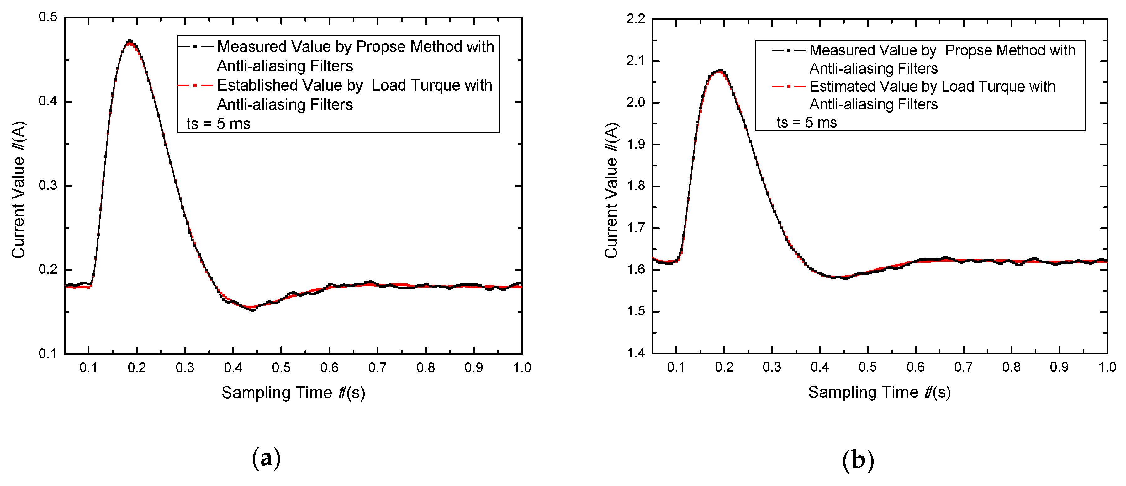
The switch S in Figure 8 is shifted to T2 to test the capability of the proposed method in measuring the large transient current of the steering motor. In the experiment, we applied a rudder load to the steering motor and measured the supply current of the motor when the control signal is step changed. The sampling interval is 5 ms, which is consistent with the UAV’s monitoring system. The measurement results were compared with the conventional method of range switching. The experimental results are shown in Figure 10.
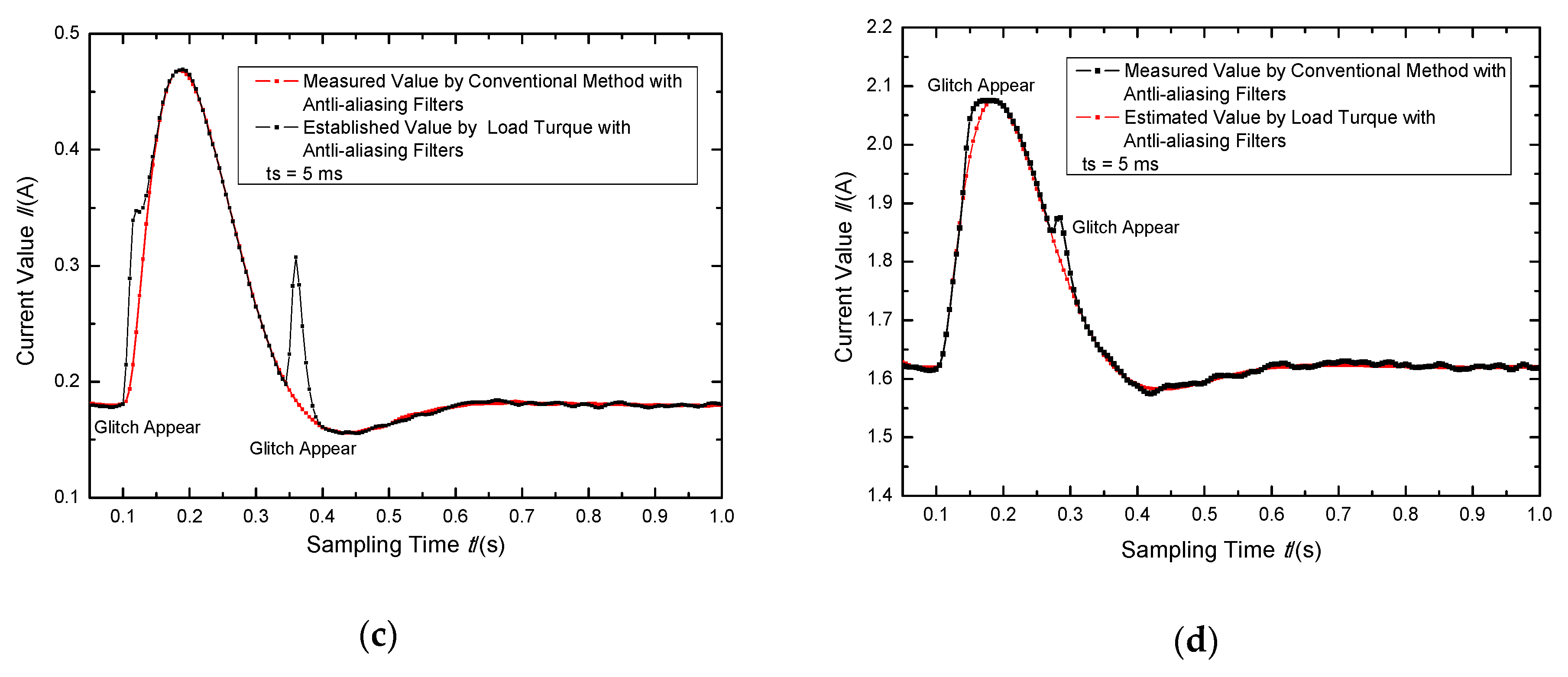
In the above figure, the red curve represents the working current of the steering motor, which is inversely deduced through mathematical model according to the load torque being applied to the steering motor. In Figure 10, (a) and (b) indicate that, if the current varies in between a large range, the conventional method needs to conduct range switching operations to obtain a higher resolution of measurement. For the conventional method, glitches occur at range switching points (200 mA and 2 A), resulting in significant false outliers. The result of turning on anti-aliasing filters (cut-off frequency is 20 Hz, 2nd order Bessel filter) is shown in Figure 10c,d, and the occurrence time of glitches is marked with additional labels accordingly. It can be seen that the proposed method can perform continuous measuring on the steering motor’s changing working current. Even if there is a large current change in the motor, outliers will not occur in the measurement result.

5. Discussion and Conclusions

The method proposed in this paper realizes the continuous measuring of a large dynamic range current that exists in the UAV’s steering motor. In contrast to conventional multi-range current measurement, the proposed method prevents frequent range switching from generating outliers. Aiming at ensuring the continuity of monitoring a large dynamic current, our method is of vital importance for UAV’s health-monitoring system. In practical applications, the proposed method still has its relative error of 3–5%, to which certain potential factors may be attributed with respect to the difference of twin diode’s consistency and of core temperature. Despite the above shortcomings, such precision is sufficient for health-monitoring, because health-monitoring takes into consideration more seriously the relative change of current. However, the proposed method can maintain the relative resolution at a relatively constant level, which is more critical than the absolute precision of measured values.
The method requires three different current values to be injected into the reference device to calculate three thermal parameters of the diode shunt. From the perspective of ensuring precision of iterative calculation, the range of these values of the injected current should cover measurement range to the largest extent, which will significantly increase the power consumption of the system. Hence, finding a trade-off between precision and power consumption can be realized by the proper reduction of the reference current value.
In solving parameters Ut, Is, rd, the proposed method adopts the gradient search algorithm, due to difficulties in finding analytical solution to transcendental equations, about which the situation brings an unpredictable time required by iterative convergence. Actual test results suggested that the required time usually varies within the range between dozens and hundreds of a millisecond. Undoubtedly, suppose the twin device exhibits its excellent heat capacity performance due to sufficient cooling, then the required calculation duration is still much smaller than the system’s thermal response time, and the temperature matching can still be considered as established.
Despite the aforementioned disadvantages, the proposed method can ensure the continuity of measurement and the consistency of relative resolution under the condition of large dynamic current. This current sensing system offers information-rich data for UAV’s health-monitoring system, facilitating real-time monitoring and malfunction analysis with respect to supply current. The proposed method can also be applied to other large dynamic current monitoring applications, including, but not limited to, industrial control, motor control, etc.

Author Contributions

Conceptualization, B.L. and S.Z. conceived and designed the PCBs; B.L. planned and performed the generator experiments; H.Z. provided the experiment facilities; F.H. conducted thermal simulation; B.L. and S.W. analyzed the data; and B.L. wrote the paper. All authors have read and agreed to the published version of the manuscript.

Funding

This research received no external funding.

Conflicts of Interest

The authors declare no conflict of interest.

References

  1. Shakhatreh, H.; Sawalmeh, A.H.; Al-Fuqaha, A.; Dou, Z.; Almaita, E.; Khalil, I.; Othman, N.S.; Khreishah, A.; Guizani, M. Unmanned Aerial Vehicles (UAVs): A Survey on Civil Applications and Key Research Challenges. IEEE Access. 2019, 7, 48572–48634. [Google Scholar] [CrossRef]
  2. Xin, G.C.; Chen, W.L.; Li, J. Research on Security Monitoring and Health Management System of UAV. In Proceedings of the First Symposium on Aviation Maintenance and Management-Volume II; Springer: Xi’an, China, 2014; pp. 631–639. [Google Scholar]
  3. Man, Q.; Ma, S.; Xia, L.H.; Wang, Y.B. Research on Security Monitoring and Health Management System of Medium-range UAV. In Proceedings of the 8th International Conference on Reliability, Maintainability and Safety (ICRMS 2009), Chengdu, China, 20–24 July 2009; pp. 854–857. [Google Scholar]
  4. Schacht-Rodríguez, R.; Ponsart, J.-C.; García-Beltrán, C.D.; Astorga-Zaragoza, C.M. Prognosis & Health Management for The Prediction of UAV Flight Endurance. IFAC-Papers OnLine 2018, 51, 983–990. [Google Scholar]
  5. Rajput, S.S.; Garg, S.C. A High Resolution Autogain Ranging Linear Electrometer Amplifier. Rev. Sci. Instrum. 1996, 67, 609–611. [Google Scholar] [CrossRef]
  6. Li, Y.L.; Zhao, H.; Zhang, G.J.; Zhang, H. Design and Implementation of High Accuracy Current Measurement Circuit Based on Resistance Sampling Method. In Proceedings of the 2018 13th World Congress on Intelligent Control and Automation (WCICA), Changsha, China, 4–8 July 2018. [Google Scholar]
  7. Pontes, E.W.; Ferreira, A. A New Method of Current Switching for Linear Wide-range Measurement Systems. IEEE Trans. Instrum. Meas. 2012, 61, 496–504. [Google Scholar] [CrossRef]
  8. Keysight Technologies, Inc. Keysight N6780 Series Source/Measure Units (SMUs) for the N6700 Modular Power System-Data Sheet. 2017. Available online: https://www.keysight.com/cn/zh/home.html (accessed on 14 July 2020).
  9. Johnson, K.W.; Brush, I.E.V.; Mctigue, M.T. Oscilloscope System and Method for Simultaneously Displaying Zoomed-in and Zoomed-Out Waveforms. U.S. Patent US2014320145 (A1), 30 October 2014. Available online: http://apps.webofknowledge.com/full_record.do?colName=DIIDW&recordID=2014U09335&log_event=no&search_mode=GeneralSearch&qid=1&log_event=yes&product=UA&SID=7ESE3wi5gPyr9FKH9iV&viewType=fullRecord&doc=1&page=1 (accessed on 14 July 2020).
  10. Eichler, J.; Novák, M. Simple Seamless Multi-Range Current Measurement for Applications with a Large Dynamic Range. In Proceedings of the 2019 12th International Conference on Measurement, Smolenice, Slovakia, 27–29 May 2019; pp. 83–86. [Google Scholar]
  11. Acharya, Y.B. A wide range linear electromete. Rev. Sci. Instrum. 2000, 6, 2585–2588. [Google Scholar] [CrossRef]
  12. Acharya, Y.B. A quasilinear wide range current electromete. Int. J. Electron. 2001, 88, 819–829. [Google Scholar] [CrossRef]
  13. Fitzgerald, R.; Bergeron, D.E.; Giblin, S.P.; Jarrett, D.G.; Judge, S.M.; Michotte, C.; Scherer, H.; Zimmerman, N.M. The Next Generation of Current Measurement for Ionization Chambers. Appl. Radiat. Isot. 2020, 163, 109216. [Google Scholar] [CrossRef] [PubMed]
  14. Ericson, M.N.; Falter, K.G.; Rochelle, J.M.A. Wide-range Logarithmic Electrometer With Improved Accuracy and Temperature Stability. IEEE Trans. Instrum. Meas. 1992, 41, 968–973. [Google Scholar] [CrossRef]
  15. Sobajlc, M.V. Possibility of Simultaneous Logarithmic-linear Direct-current Measurement. IEEE Trans. Instrum. Meas. 1976, 25, 34–43. [Google Scholar] [CrossRef]
  16. Lookin, N.A.; Rubin, L.S. Precision Nonlinear Low Current Meter. In MECHANICS, RESOURCE AND DIAGNOSTICS OF MATERIALS AND STRUCTURES (MRDMS-2019): Proceedings of the 13th International Conference on Mechanics, Resource and Diagnostics of Materials and Structures; AIP Publishing: College Park, MD, USA, 2019. [Google Scholar]
  17. Li, B.W.; Wang, L.; Casati, G. Thermal diode: Rectification of heat flux. Phys. Rev. Lett. 2004, 18, 184301. [Google Scholar] [CrossRef] [PubMed] [Green Version]
  18. Corless, R.M.; Jeffrey, D.J. The Wright Omega Function. In Proceedings of the Artificial Intelligence, Automated Reasoning, and Symbolic Computation, Joint International Conferences, AISC 2002 and Calculemus 2002, Marseille, France, 1–5 July 2002; pp. 76–89. [Google Scholar]
  19. Singh, L.L.; Gartia, R.K. Derivation of a Simplified OSL OTOR Equation Using Wright Omega function and Its Application. Nucl. Instrum. Methods Phys. Res. Sect. B 2015, 346, 45–52. [Google Scholar] [CrossRef]
  20. Lawrence, P.W.; Corless, R.M.; Jeffrey, D.J. Algorithm917: Complex Double-Precision Evaluation of the Wright omega Function. ACM Trans. Math. Softw. 2012, 38, 20. [Google Scholar] [CrossRef]
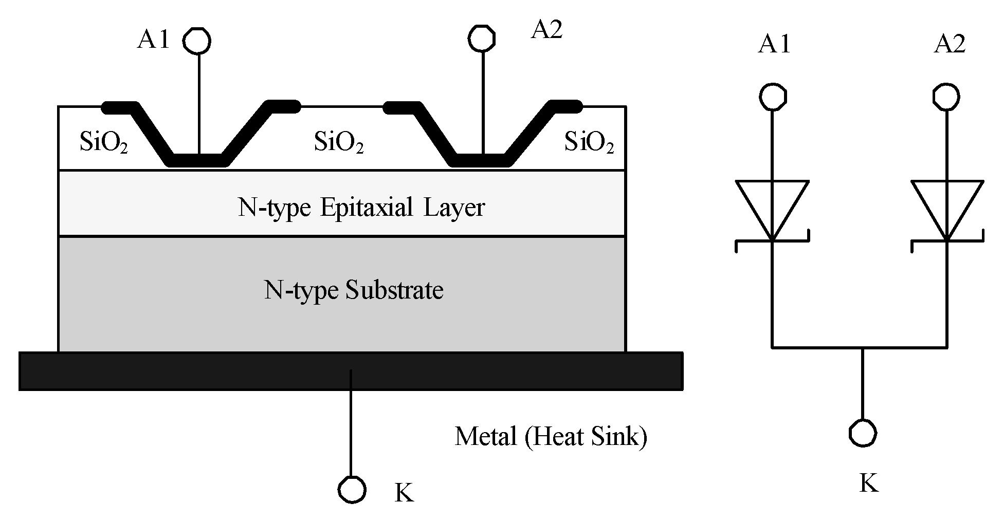
Figure 1. Structural diagram of a twin diode.
Electronics 09 01240 g001
Figure 2. (a) Schematic internal structure of a twin diode, (b) diagrams showing thermal profiles of a twin diode (10 mA), (c) of a twin diode (1 A) and (d) of a twin diode (10 A).
Electronics 09 01240 g002
Figure 3. Current measurement method based on twin diode.
Electronics 09 01240 g003
Figure 4. The equivalent model of diode under large current.
Electronics 09 01240 g004
Figure 5. Diagram showing comparison between fitting curve and measured curve.
Electronics 09 01240 g005
Figure 6. (a) Conventional current measuring circuit, and (b) twin-device-based continuous current measuring circuit.
Electronics 09 01240 g006
Figure 7. Circuit design of large dynamic current detection based on twin nonlinear device.
Electronics 09 01240 g007
Figure 8. Diagram showing relation between resolution Ires and current to be measured Im.
Electronics 09 01240 g008
Figure 9. Experimental setup for testing current measurement performance of the proposed method.
Electronics 09 01240 g009
Figure 10. Measurement result obtained by performing (a) the proposed method on small continuous working current of the steering motor, (b) the proposed method on large continuous working current of the steering motor; and measurement result obtained by performing (c) conventional method on small continuous working current of the steering motor, (d) conventional method on large continuous working current of the steering motor.
Electronics 09 01240 g010aElectronics 09 01240 g010b
Table 1. Uniformity of current-voltage characteristics of twin diodes at 25 °C.
Ambient Temperature = 25 °C
Forward CurrentVoltage (A1-K)Voltage (A2-K)Error (%)
0.01 A0.479 V0.473 V1.2%
0.10 A0.597 V0.591 V1.0%
1.00 A0.720 V0.711 V1.2%
10.0 A0.897 V0.887 V1.1%
Table 2. Uniformity of current-voltage characteristics of twin diodes at 100 °C.
Ambient Temperature = 100 °C
Forward CurrentVoltage (A1-K)Voltage (A2-K)Error (%)
0.01 A0.349 V0.344 V1.3%
0.10 A0.456 V0.451 V1.2%
1.00 A0.706 V0.698 V1.2%
10.0 A0.853 V0.842 V1.1%
Table 3. Relative error of the proposed current measurement circuit.
ItruthImIresAI
10.10 mA10.24 mA0.07 mA2.5%
29.9 mA30.88 mA0.29 mA2.8%
100 mA103.10 mA0.90 mA3.1%
300 mA310.13 mA2.59 mA3.3%
1.01 A1.03842 A6.44 mA3.8%
2.99 A3.11730 A12.15 mA3.9%
9.98 A10.43322 A16.87 mA4.3%