Abstract
Optical wireless communications (OWC) are emerging as cost-effective and practical solutions to the congested radio frequency-based wireless technologies. As part of OWC, optical camera communications (OCC) have become very attractive, considering recent developments in cameras and the use of fitted cameras in smart devices. OCC together with visible light communications (VLC) is considered within the framework of the IEEE 802.15.7m standardization. OCCs based on both organic and inorganic light sources as well as cameras are being considered for low-rate transmissions and localization in indoor as well as outdoor short-range applications and within the framework of the IEEE 802.15.7m standardization together with VLC. This paper introduces the underlying principles of OCC and gives a comprehensive overview of this emerging technology with recent standardization activities in OCC. It also outlines the key technical issues such as mobility, coverage, interference, performance enhancement, etc. Future research directions and open issues are also presented.
1. Introduction
The rapid increase in the data being generated and the growing demand for capacity have pushed existing congested radio frequency (RF)-based wireless communications to their limits. In addition, we are witnessing incommensurate spectral efficiency as well as bandwidth with increasing traffic demands and requirements in the RF domain [1]. From a futuristic perspective, it is foreseen that high-rate and high-capacity RF communications coexist with more affordable, offloading, and unlimited bandwidth wireless communications. As an attractive complementary solution, optical wireless communications (OWC) have been considered for easing the bandwidth usage pressure on RF wireless systems in a harmonious manner. OWC covers the entire optical spectrum of ultraviolet (UV), visible and infrared (IR) [1,2], see Figure 1, thus offering a massive theoretical bandwidth of 20 THz (IR), 320 THz (visible) and 30 PHz (UV) compared with the bandwidth of 300 GHz in the RF technology [1,3,4]. Within the OWC umbrella, there are a number of transmission schemes for both indoor and outdoor environments including infrared communications (IRC), free space optics (FSO), visible light communications (VLC) and ultraviolet communications (UVC) [1,3,4,5,6], as shown in Figure 2. The VLC and IRC are generally considered for short-range indoor applications, while FSO (using the IR band) and UVC (using the C band) are predominantly employed for medium-long range outdoor environments. Note that FSO can also use the visible band for short to medium range transmissions.
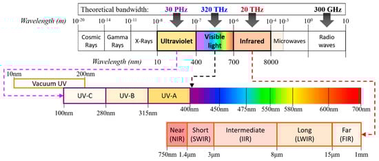
Figure 1.
The electromagnetic spectrum.
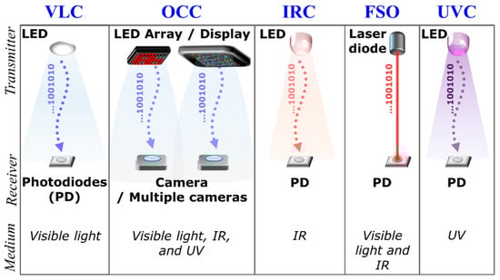
Figure 2.
Overview of optical wireless communications (OWC) transmission schemes.
The VLC technology, a subset of OWC as defined in the IEEE 802.15.7, has specifically been envisioned for high capacity mobile data networks since 2000, to complement the RF-based mobile communications [1,7,8,9,10]. The popularity of VLC development is driven by its efficiency in utilizing existing light-emitting diodes (LEDs)-based lighting infrastructure as the transmitter (Tx) to offer significantly higher luminous efficacy, data communications and indoor localization [1,9]. In contrast to other lighting sources, LEDs can be switched at a very high speed, thus facilitating data transmission that can be picked up using photodiodes (PDs) or image sensors (ISs).
A VLC system employing an IS, i.e., a camera, is known as optical camera communication (OCC) according to the standards, which requires no hardware modifications [5,11,12]. The IS in a camera, which is a massive matrix of μ-scale PDs, together with a lens, can be used to provide an imaging massive multiple-input multiple-output (MIMO) system, i.e., enabling spatial separation of light sources on the IS. In addition, the camera (IS)-based receiver (RX) is capable of capturing information not only from multiple TXs (i.e., LEDs) but also from digital displays such as liquid crystal display (LCD) and organic LED (OLED)-based screens [5,12].
Furthermore, an OCC image capturing increases the communication range in outdoor environments up to a kilometer, due to the use of image processing, long sampling duration and lenses [5]. Nevertheless, most OCC schemes reported in the literature are intended for indoor applications because of smart-devices availability and a lower intensity of ambient light in indoor environment [5].
With regard to the OCC, it is important to note that OCC-based systems are mainly targeted for a low-rate transmission, due to the reception-sampling rate, which is determined by the camera frame rate FR, which is typically in the range of 30 to 60 frames per second (fps) at a common resolution of 1920 × 1080 pixels. However, with current advances made in cameras, for the same resolution, FR of new smartphone cameras can reach up to 960 fps [13]. Different from VLC that uses a PD to process the received optical intensity, OCC is based on capturing the source using the IS, i.e., a two-dimension (2D) RX containing millions of pixels, and carrying out a significant amount of image processing to acquire the information. Therefore, the data transmission rate of OCC is mostly limited to either kilobits per second (Kbps) or megabits per second (Mbps) in contrast to multi-gigabit per second (Gbps) transmission rates in PD-based VLC systems [1,5,11,14].
The IEEE 802.15.7 standard was initially formulated in 2011 for VLC without considering the IS-based RX [1,11]. In 2014, however, OCC was included in the revised IEEE 802.15.7r1 standard [11,15], which was managed by the TG7r1 task group and covered wider light spectra such as near infrared (NIR) and near UV [5,11]. OCC is currently organized by the updated task group TG7m that finalized the initial draft in 2018 [14,16]. The task group is a joint consortium of academic researchers from multiple countries including United States, South Korea, Turkey, Taiwan and China [16].
Due to the inclusion of nearly the entire optical spectrum in the standardization, there are a wide range of potential applications for OCC within the context of Internet-of-things (IoT) such as augmented reality, color code, device-to-device communications, digital signage, exhibition/store service, in-flight service, indoor positioning, vehicular communications and underwater/seaside communications [5,17,18]. At a global level, a number of companies including Fraunhofer Heinrich Hertz Institute (Germany), Intel (United States), Panasonic (Japan), Casio (Japan), Huawei Technologies (China), Electronics and Telecommunications Research Institute (Korea), LG Electronics (Korea) and China Telecom (China) have been working on the application of OCC [5].
In recent years, the interest in OCC has been growing, judging from four surveys published in the past four years, mostly driven by the early standardization activity (i.e., IEEE 802.15.7r1) [5,11,17,18]. The first survey focused on key technologies used in OCC [11], while the second survey investigated various implementation challenges associated with OCC with no comprehensive structures [17]. The third survey covered concise performance analysis of OCC intended for inclusion in the fifth generation (5G) wireless networks [5]. Finally, the fourth survey, which was the most recently published work, is a broad survey of OCC covering localization, navigation, motion capture, and some insights into future research direction [18,19]. This survey, however, only introduced several challenges and future research directions in the limited sense.
This paper, on the other hand, presents a comprehensive survey on OCC in such a way that it focuses heavily on the principles and modulations of OCC to date, together with potential applications and future research directions in mind. It also outlines key technologies and standardization as well as modulation schemes that have been proposed and investigated. The paper aims to enhance practical implementations of OCC, while disseminating promising OCC technologies and future challenges.
The rest of the paper, as illustrated in Figure 3, is organized as follows. Section 2 describes OCC in detail and Section 3 reviews existing modulations of OCC. Section 4 presents various performance enhancements in terms of mobility, coverage, and interference. Section 5 is dedicated to recent OCC schemes for both indoor and outdoor applications. Section 6 discusses future potential developments, enhancements, and challenges in OCC. Finally, Section 7 closes the paper with a brief summary. In addition, Appendix A shows a list of both abbreviations and acronyms used throughout the paper.
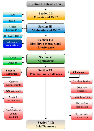
Figure 3.
The paper organization.
2. Optical Camera Communication
2.1. Principles
OCC employs either a single or multiple-camera setup as the RX, which can now be found in most mobile devices such as mobile phones, smart watches, laptops, tablets, as well as vehicles and buildings [2]. Therefore, the existing LED lighting fixtures and widely used cameras, i.e., cheaper and off-the-shelf devices, can be employed in OCC. While the majority of VLC systems are limited to utilizing the visible light spectrum, OCC employing different types of camera can utilize the entire light spectrum from visible light, NIR to UV-C band. In OCC, the camera captures images/video streams of the intensity modulated light sources, i.e., a single LED, multiple LEDs and digital display screens, and extracts the information by means of image processing [17]. Thus, camera-based OCC can be used in both indoor and outdoor environments for a range of applications [11]. The development of complementary metal-oxide semiconductor (CMOS) sensor technologies has created a new generation of high-pixel-resolution and high-speed built-in cameras [11,17]. Although most cameras capture images at a FR of 30 to 60 fps, the OCC standardization covers high-speed cameras, which can support a FR of up to thousands of fps [5,11].
Similar to VLC, OCC predominantly relies on the directional line-of-sight (LOS) transmission mode. In addition, OCC conveniently offers a MIMO capability by extracting the data from captured multiple light sources. Therefore, for these reasons, OCC can be considered as a subset of VLC. It is interesting to note that the imaging MIMO capability of the camera can also be exploited for other applications, such as range estimation, shape detection, scene detection, etc.
2.2. Standardization
OCC has been in the process of standardization since 2014 by the IEEE 802.15.7r1 task group TG7r1, which is a revised version of IEEE 802.15.7 standard for VLC [11,20,21]. OCC is considered as an extension of the VLC standard in IEEE 802.15.7 that was initially defined as a specific task group to formulate the standard revision for VLC, which is called the IEEE 802.15.7-2011 standard [1]. The task group for OCC was renamed to IEEE 802.15.7m OWC Task Group TG7m in order to develop technical specifications for the OCC standard [14]. TG7m covers NIR (700–1000 nm wavelengths), UV (100–400 nm wavelengths) and visible light (400–700 nm wavelengths) bands. The TG7m task group has contributed to various OWC solutions including OCC, LED Identification (LED-ID) and LiFi [14]. OCC is alternatively known as IS communications (ISC) or camera-based VLC, since it utilizes an IS as the RX, which provides a supplementary functionality of communications in addition to video streaming and image capturing [22,23,24].
Figure 4 illustrates different examples of OCC considered in TG7m, highlighting vehicular communications (vehicle-to-vehicle (V2V) and vehicle-to-infrastructure (V2I)) and indoor applications [14]. Additional standardized applications were proposed in late 2018 by TG7m, such as 2D color code, TX/RX relay, digital signage, exhibition/store service, in-flight service, underwater (or seaside/coastal) communications, drone-to-drone, smart living, street-lamp access point, smart city, smart factory, and smart house [14,25,26]. These applications are classified into flicker and flicker-free physical (PHY) layer modes, depending on the switching rate of the TX being perceptible or imperceptible to human eyes, respectively.
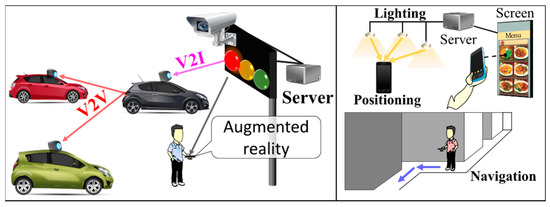
Figure 4.
Example of promising services in IEEE 802.15.7m.
Regarding modulations, five additional schemes are standardized to deliver optimum performance in OCC. That is, according to the finalized document in 2017, the TG7m Committee approved additional sets of OWC PHY operating modes, i.e., PHY IV to PHY VIII, as shown in Table 1. PHY IV, V, and VI are directly related to OCC developments, while PHY VII and VIII are intended for LiFi. In direct detection VLC systems, the simple on-off keying (OOK) and variable pulse position modulation (VPPM) schemes were adopted in the initial version of the IEEE 802.15.7-2011 standard. Table 2 details the OCC modulation schemes that were introduced in the IEEE 802.15.7m standard for PHY IV, PHY V, and PHY VI. The next revised draft of the standard, known as IEEE 802.15.7-2018, was finalized in 2018 [27,28]. More detailed OCC technologies are presented in Section 3 and Section 4.

Table 1.
IEEE 802.15.7m initial operating modes.
Table 2.
IEEE 802.15.7m: Characteristics and performance estimation of OCC technologies.
2.3. Transceivers
The operation and performance of IS-based OCC systems are affected by both the IS characteristics and camera’s image processing [17]. In digital cameras, the IS is typically based on the CMOS architecture, which is a mature, highly developed and less costly technology than charge-coupled device (CCD)-based cameras [29]. Note that the size of CMOS-based ISs is increasingly smaller, while still offering higher resolution images with high pixel density. Smaller sized CMOS ISs are made possible using the advanced electronics fabrication technology with a 7 nm manufacturing scale [30].
As shown in Figure 5, a typical camera structure is composed of an imaging lens, a color filter array (CFA), an image sensor (IS) and an image processing unit (IPU) [29]. The lens projects the light illuminated or reflected from a light source or an object on the IS, respectively. The diagonal field of view (FOV) of the camera is determined by the focal length of the camera lens and the sensor size as illustrated in Figure 6. In addition, the working distance defines the distance for the camera to capture the image in focus.
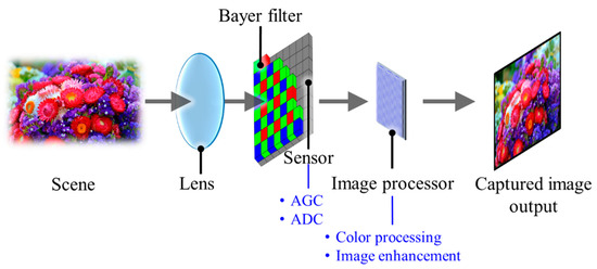
Figure 5.
A brief schematic of a digital camera.
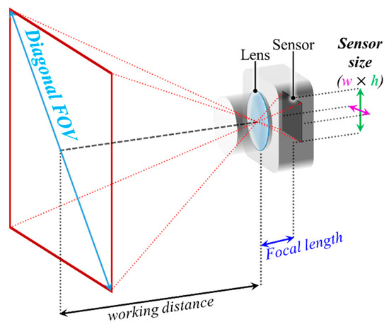
Figure 6.
A diagonal field of view (FOV) of a camera.
A CFA typically with Bayer pattern records the color information of the illuminated light in a spatial configuration [31]. Bayer pattern is structured based on 2 × 2 blocks of filters (i.e., one blue, one red, and two green), which can have different arrangements of BGGR, RGBG, GRGB or RGGB. The reason for more green filters is the human eye, which is more sensitive to the green light; hence, more information about the green color is required [32]. The image is then processed by an image processor utilizing a demosaicing algorithm, also known as deBayering, to reconstruct the image colors similar to the real scene, as illustrated in Figure 7 [31,32]. The output of the IPU is then processed to extract the information in the image.
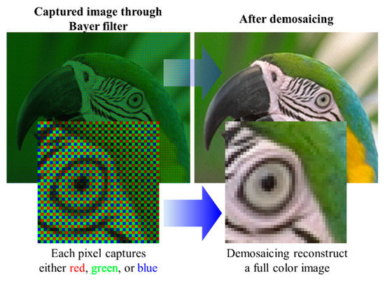
Figure 7.
An example of the demosaicing process.
The internal shutter mechanism of cameras determines the exposure of pixels in the IS. Two main types of ISs in terms of the architecture are CCD and CMOS [33]. A CCD sensor has a larger physical dimension due to the utilization of a relatively larger analog-to-digital converter (ADC), compared with a CMOS IS [29,34]. Therefore, CCD is not generally implemented in mobile devices, especially smartphones. In comparison with CCD, CMOS cameras provide lower power consumption, smaller IS, faster readout, lower cost and more programmability. In addition, since pixel scanning is based on the X–Y address scheme in the CMOS architecture, direct access to a desired part of the IS is possible, which can increase the FR at the cost of reduced FOV [35,36]. Cameras can have two different exposure methods, i.e., global shutter (GS) and rolling shutter (RS), as illustrated in Figure 8a. In the global-shutter-based ISs, the entire sensor is exposed to the light at the same time, whereas in the rolling-shutter-based cameras, each row is exposed to the light at a time, thereby considerably reducing the power consumption. CCD sensors inherently capture images using the GS, while the exposure method in most CMOS ISs is based on RS [29,33].
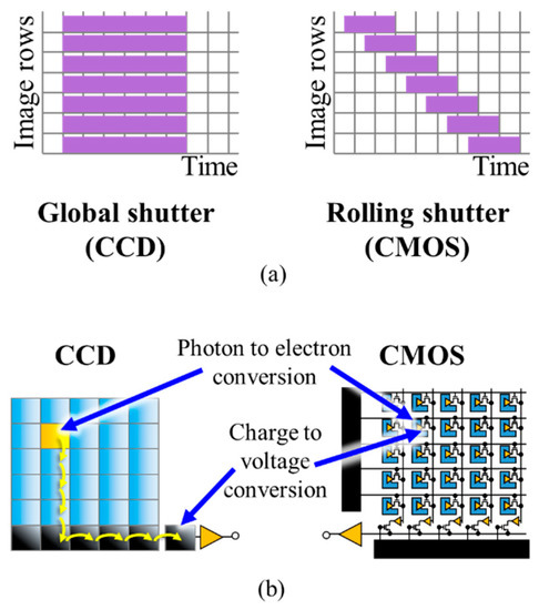
Figure 8.
(a) A comparison between the GS and RS; (b) a structural comparison between CCD and CMOS sensors.
It should be noted that in the global-shutter-based CCD ISs, considerably longer frame capture time is needed to convert the charge into a voltage signal [29]. Figure 8b shows the structures of CCD and CMOS sensors [29]. Due to the fabrication of much more compact ADC for each pixel, the CMOS sensor is preferable nowadays compared with relatively larger CCD sensors. CMOS is also employed for high-speed cameras with FR > 1000 fps, which cannot be accomplished using the CCD sensors due to slower ADCs. Note that the CMOS sensor in smartphone cameras is capable of reaching an FR of 1000 fps [13,37]. The shutter methods are implemented within the sensor itself; however, the information can be treated differently as part of image processing following image capturing, which is related to the OCC modulation schemes. The detailed description of modulation schemes based on RS in OCC is provided in Section 3.
As mentioned previously, OCC only utilizes CMOS sensors, since it is widely employed in the majority of mobile devices including smartphones [11,17]. With regards to image capturing in OCC, CMOS sensors can have either GS or RS mechanism, depending on the image processing algorithms and the TX switching rate [5,17,22,38,39]. For example, a camera with a full high definition (FHD) resolution (1920 × 1080 pixels) and a frame rate of 60 fps employing the GS mechanism can sample 60 complete frames every second. On the other hand, the identical camera with RS processes individual rows on each frame as a sample, thus yielding a sampling rate of 64,800 (60 × 1080) samples per second (sps).
The complete frame capture period comprises the exposure and frame-saving periods as shown in Figure 9a. The exposure time, which can be set by the camera controller, is a period when the IS is exposed to the light. In the RS cameras, the rows of the IS are exposed sequentially. Therefore, each pixel in a row of frame is treated as an individual sample, which increases the sampling rate by thousand times, thus offering data rates much higher than FR. Figure 10 demonstrates the LED status and the intensity in each row of the IS against the time. It is important to note that the switching rate of the transmitting LED should be set to be lower than the sampling rate of the RS mechanism.
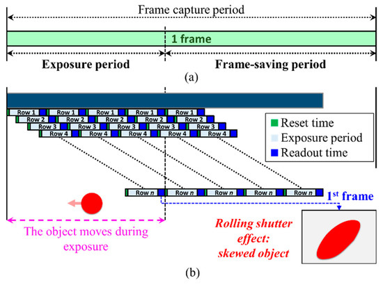
Figure 9.
(a) Frame capture period; (b) RS distortion causing a skewed object in the capture frame.
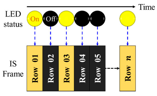
Figure 10.
RS mechanism on image sensor for data capture.
Following the exposure time Texp, the camera’s shutter is closed, followed by the image processing (including image compression) as well as saving the frame. Customarily, the image processing and frame saving are called the frame saving period. Obviously, the frame saving period is determined by the speed of the IPU and the storage device. In the RS, the frame-saving period is compressed by pipelining the readout time sequentially on each row as illustrated in Figure 9b.
The RS mechanism in CMOS, however, has an undesirable skew in the captured frame (i.e., RS distortion) during object capturing. This is due to the fact that the object moves at a high speed during the exposure period as illustrated in Figure 9b [29,39]. In order to avoid this RS distortion for a 10-percent blur threshold, the exposure time must meet the following condition [39]:
where and denote the object’s displacement and velocity, respectively. However, the image distortion is largely discounted as the image-capture functionality of the camera is ignored. The primary concerns of the RS-based OCC are image skew, link range and the limited camera resolution.
Meanwhile, in the GS-based OCC with an N × M pixels IS with each pixel producing G-level grayscale signals and FR, a theoretical maximum achievable data rate limit is given by [5,40,41]:
The constant value of 1/8 is a rate reduction factor for three-dimensional signals, which is a downsampling factor for the data rate in a camera to avoid spatial aliasing, since the pixels in an image sensor are densely organized [41]. The rate reduction factor can only be omitted from the equation when each pixel in the image sensor is placed with adequate gap [41]. For example, a camera with a full high definition (FHD) resolution (1920 × 1080 pixels), 256 levels of grayscale in the IS with a of 60 fps yields a theoretical maximum achievable data rate of 124.42 Mbps [41]. However, this data rate can only be obtained when each IS pixel is illuminated by an independent TX. Unfortunately, this individual illumination is impractical due to the transmission distance between the camera and the TX.
To carry out a more accurate measurement of the captured image, a minimum of two pixels per the smallest feature is required. The smallest feature indicates the size of a smallest identifiable property in an image, i.e., a clear shape and color. The minimum IS (camera) resolution is then two times the size of FOV (), either horizontal or vertical FOV, divided by the smallest feature . Therefore, to capture a clear image, the minimum resolution of the camera is given as [42]:
For example, if the FOV covers 100° and the smallest feature is 1 mm, the required minimum resolution is 200 pixels. Thus, a camera with a resolution of 640 × 480 pixels would be adequate. This is because 200 pixels are less than 480 pixels, which is the smallest dimension. In other words, the number of pixels (in IS) define the maximum distance of capturing a clear image, related to the FOV in Equation (3) and its working distance illustrated in Figure 6.
In a camera-based OCC, a range of TXs can be adopted, e.g., digital display modules and LEDs [5,17,22,36,38]. Color filter arrays, wavelength division multiplexing (WDM) and color shift keying (CSK) based on RGB LEDs or displays have been employed in OCC [5]. Interestingly, the typical refresh rate of a digital display is ~60 Hz, which is in the same range of FR [38]. The type of digital display used as the TX is either LED, LCD screen, OLED, or e-paper [5,17,38,43]. In display-to-camera communications, multiple colors with multiple intensity levels are deployed for each pixel, since the illumination footprint is mapped on the spatially separated PDs of the IS. Since current display devices support FHD resolution, higher data rates can be achieved.
2.4. Channel Characteristics
Although the OCC channel is largely considered to be free space, other mediums such as vacuum, gas and water can also be used [5,14]. In OCC, the transmission mode can be LOS [1,2,3], non-LOS (NLOS) [4,5] or a combination of both. The channel impulse response for the LOS link can be represented as a matrix , where and are the numbers of rows and columns of the image sensor, respectively and is the channel impulse response of the -th pixel. Using a single LED and a Gaussian mixture model, is estimated as [6]:
where , is the pixel length, and are the magnification factors of the camera at a reference link span and at a distance of , respectively. and with denoting the parameter of the model and and are the standard deviations in the x and y directions on the image plane, respectively. In (4), and , where and are the coordinates of the center of the image and nearest pixel to this center, respectively and is the gap between two pixels. Figure 11 illustrates the coordinates system visually.
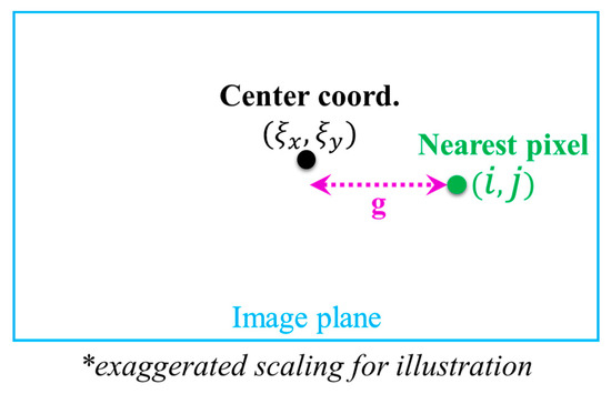
Figure 11.
Image plane coordinates system.
Most OCC systems reported are based on the LOS configuration. However, in scenarios where TXs are not within FOV of the LOS, such as two vehicles approaching crossroads, the channel will be via NLOS paths. In NLOS links, reflected beams normally have large off-axis projected optical illumination footprints that can increase link tolerance to the camera movements.
Considering the NLOS OCC link, the camera’s -th pixel is given by [44]:
where and denote the area of the aperture and the reflection coefficient, respectively. and are radiation patterns of the LED and the reflection element, respectively. and are the boundaries of the area covered by pixels in and dimensions, respectively. is the distance between the TX and the reflecting element , and is the distance between the camera and the reflecting element. For a matte surface, reflections follow the 1st order Lambertian pattern.
For the camera, the incident angle is given by:
where and are the unitized incident beam and the camera plain normal vector, respectively, and the dot is the inner product. For the CMOS active pixel, the frequency response as a function of the amplification gain G per pixel and the angular frequency is given by [45]:
In (7), the 2nd term represents the delay of between the center of the exposure and when the sample is actually read, while the 3rd term is the frequency response of integrating over .
One advantage of OWC against RF communications is the channel modeling, which involves considerably higher frequencies of the optical signal, compared with the optical clock signal [17]. Thus, the multipath fading and the Doppler effect can be ignored. For OCC, the signal-to-noise ratio () can be obtained as [17]:
where and denote the noise and received signal powers, respectively. is the channel impulse response (the channel DC gain), denotes the camera’s responsivity, denotes transmit power of -th light source, denotes the electron charge, represents ambient light per unit area, is the area of the PD (area of the IS) and .
Depending on the focusing distance of the camera lens, the received power can be projected on a single PD or multiple PDs, which are known as focused and defocused modes, respectively. Figure 12 shows different focusing scenarios based on the TX’s location [17], in which and indicate the height of the object and its projected height on the sensor, respectively. Moreover, shows the distance between the lens and the object, whereas is the distance from the lens to the IS. When the camera is defocused, the image of a point source will illuminate an area of IS with the same shape of the lens aperture, which is typically a circle. This area is known as a circle of confusion (CoC). The shape of the defocused image can be obtained as [46,47]:
where, is the CoC disc function, is Heaviside step function, is the intensity function of the image when the TX is in focus and is the 2D convolution operation. is the diameter of the CoC and is given by:
where , , and are the lens aperture diameter, camera lens focal length and f-stop of the aperture, respectively.
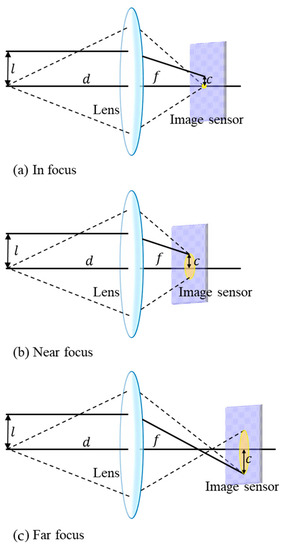
Figure 12.
Lens focuses incoming light on the IS: (a) in focus; (b) near focus; (c) far focus [17].
While SNR calculates signal-to-noise intensity on a sensor as a single unit, a more specific approach for the energy to noise ratio () calculation on the IS of a camera is provided to estimate the amount of light reaching each pixel of the sensor, compared with the light interference [5]. In this regard, the value per pixel on the IS, which is directly related to the amount of illuminance received, which is given by:
where denotes the energy per bit, denotes the noise spectral density, is the pixel value, is the amplitude of the signal (light), is the camera exposure duration as a ratio of the signal cycle, is noise value and both and are noise model fit parameters. In addition to the signal quality evaluation for OCC reception, the peak signal-to-noise ratio (PSNR) approach is often considered for the image quality evaluation in OCC with the GS and reflects the quality of OCC channel in terms of 2D image degradation [48]. The PSNR is formulated in OCC as a ratio of the original image quality (transmitted) to the captured image/frame quality, which is degraded by the channel impairments, and is given by [37,48]:
where denotes a matrix containing the mean of the maximum pixel value of RGB color channels in the originally transmitted image. is the average value of mean squared error () from all RGB color channels. Calculating a noise-free monochrome original image () with a resolution of pixels and the noisy captured frame (), the for each color channel (either R, G, or B) is defined as:
3. Modulations
Modulations and coding schemes are the key drivers in the performance of a communications system. In OCC where a camera is employed as the RX to capture the 2D image of the TX, the information data can be used to modulate color, intensity, spatial coordinate (defined by camera resolution) and the form of shape of the source [5,14,17]. It is worth noting that these modulation options are limited, due mainly to the number of cameras; therefore, the TX is manipulated in order to compensate for the number of the RX that could be employed. In OCC, there are several factors that determine the modulation schemes, such as IS type, exposure time, ISO, image processing, type of TXs and human eye perception. Broadly speaking, the OCC modulation can be classified into four major categories: Nyquist sampling modulation (NSM), region-of-interest signaling (RoI-S), hybrid camera-PD and RS-based modulation.
3.1. Nyquist Sampling Modulation
The principle of NSM is based on limiting a switching/refresh rate Rs of the TX to be less than or equal to 0.5FR in order to comply with Nyquist sampling theorem as shown in Figure 13 [5]. Since FR is mostly limited to 60 fps, the TX’s Rs is generally set to 30 Hz for NSM. Furthermore, due to a low Rs of the TX that causes perceptible flicker to the human eyes, NSM generally utilizes a digital display as the TX instead of LEDs, since display flickering is less discomforting than LED [5,17,49]. Moreover, a single LED TX is not used in NSM since the effective data rate is limited to be lower than 60 bps.
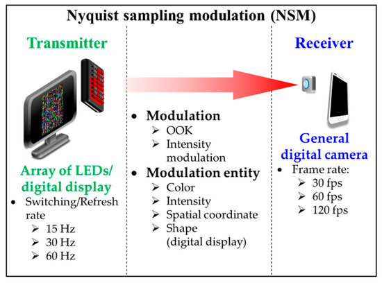
Figure 13.
Nyquist sampling modulation.
In NSM, the data transmission throughput is limited by FR. To increase the data rate, multi-dimension modulation schemes based on colors, intensity levels, and shapes spread across space (spatial coordinate) are employed [5,11,17]. Initial studies related to NSM OCC based on digital display are PixNet and COBRA codes [50,51]. PixNet encodes the bits in the frequency domain using 2D orthogonal frequency division multiplexing (OFDM) modulation, thus offering throughputs in the order of several Mbps with the processing time limited by the clock rate (i.e., capping the TX to 5 Hz) [50]. In [51], an enhanced 2D color code known as COBRA codes (i.e., in the form of colored QR codes) was reported in order to optimize real-time streaming using five colors and three optional colors with a higher transmission rate of 10 Hz. It introduced a concept of embedding anchors, at the corners (CT) and borders (TRB) of the transmission frame to synchronize between adjacent frames during reception [51]. The synchronization between camera frame rates and the switching rate of TXs using LightSync was investigated in [52].
The 2D sequential coding scheme was the first used in the NSM following COBRA, which employed modulation entities of spatial coordinate (cell) and color with the support of anchors on the corners [53]. This scheme functions as a dynamic colored QR code and performs synchronization. In addition to the 2D-sequential coding, an invisible watermarking was proposed to reduce discomfort from perceptible flickers by varying the color chromaticity slightly as part of modulation [12,54]. The transmission frame was divided into m × n embedded cells as shown in Figure 14 with 4 × 2 embedded cells. The change in chromaticity within each cell, i.e., the mean value of blue, is imperceptible by human eyes since they are less sensitive to the blue; however, these changes in chromaticity can be perceived by the camera and thus decoded as invisible watermark codes.
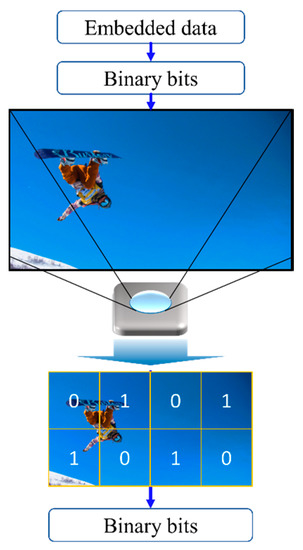
Figure 14.
Invisible watermarking OCC.
Several studies employed NSM with an array of LED TXs and provided a higher light intensity, compared with digital display, thereby achieving a longer transmission range [22,55,56,57]. In [22], some additional LEDs were employed for illumination, camera focusing and light metering that are required due to the flickering LEDs. On the other hand, the color-intensity modulation multi-input-multi-output (CIM-MIMO) scheme was proposed using an accelerated smartphone camera with the image processing carried out in FPGA to achieve a higher FR of 330 fps [55]. It achieved a data rate of 126.72 Kbps over a longer transmission range of 1.4 m. An alternate approach, termed the split-shutter, was presented using a pair of camera setup to increase the FR by splitting the captured image between two cameras; thus, it yields a data rate of 11.52 Kbps over a link span of 144 cm using off-the-shelf smartphone cameras [43].
In the IEEE 802.15.7m standard, an interesting modulation scheme that may increase the OCC data rate dramatically was proposed [14,16]. It is a shape modulation called variable transparent amplitude shape code (VTASC) as illustrated in Figure 15. VTASC was experimentally evaluated in OCC in a form of high-density modulation (HDM) with a neural network (NN) assisted demodulation scheme [37]. The HDM, forming the most complex NSM, modulates color, intensity and shape simultaneously in a cell (a spatial coordinate). Thus, yielding 13-bit modulated data on each cell. The NN was adopted for classifying the shapes efficiently on the receiver side [58,59]. The HDM achieved an effective data rate of 2.66 Mbps over a short transmission distance of 20 cm, which can be considered appropriate for device-to-device (D2D) communications.
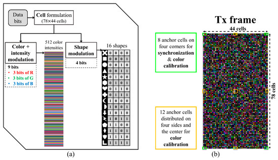
Figure 15.
(a) A high-density modulation scheme and (b) example of an HDM-generated TX frame.
On the other hand, a high-rate NSM shown in Figure 16 is similar to NSM except for the use of a high-speed camera with the FR of 1–10,000 fps [5,60,61], thus increasing the Rs of the TX (i.e., LEDs) to be higher than 100 Hz. However, a digital display can also be used with Rs still limited to 144 Hz for FHD resolution. Note that a high-rate NSM offers an advantage when utilizing LEDs with Rs higher than the flicker fusion threshold, i.e., perceptible flicker by human eyes, thus preventing discomfort to the users [43,62].
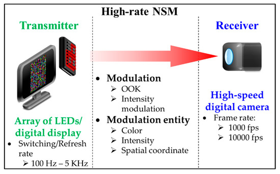
Figure 16.
High-rate Nyquist sampling modulation (NSM).
The high-rate NSM is, however, not readily applicable to smartphones. Furthermore, the use of a high-speed camera is envisioned for V2V and V2I outdoor applications only, since vehicles are traveling at high speeds, thus requiring flicker-free transmission due to traffic regulations [5,60,63]. Even though these schemes are proven to be reliable, they are, in general, relatively unattractive for OCC due to a considerable cost of both high-speed cameras and high-performance image processing hardware.
3.2. Region-of-Interest Signaling
Region-of-interest signaling (RoI-S) is an improvement of NSM that utilizes the region of interest (RoI) in image post-processing in order to reduce the portion of the image capture [5,64,65]. RoI reduces the resolution of the image being processed at the RX and thus the proposed RoI-S method offers a more efficient and faster processing time than the NSM-based OCC. The implementation of RoI-S is based on the combination of NSM and high-rate NSM schemes.
ROI-S utilizes a low-rate camera to fix the ROI first, then carries out the actual reception using a high-rate camera employing the previously set ROI. It is necessary for ROI-S to use two cameras since the original ROI method is post-processing (after the capture has been completed) and the rate cannot be changed anymore afterward.
It is indeed possible to use a single camera with a variable-sized capture frame (different from post-processing ROI) that effectively reduces the resolution and increases the capture rate during the frame capture, which is called Selective Capture as proposed in [33]. Selective Capture is an alternate form of the RoI-S that was proposed as part of pre-processing (i.e., during the capture) in order to shorten the frame capture period, thus resulting in an overall higher FR [36].
Figure 17 shows that the RoI-S carries two reception streams with different frame rates, i.e., a low rate stream for determining the RoI (i.e., RoI signaling) and a high rate stream for the high-rate OCC (i.e., high-rate MIMO data stream) [17,64]. Note that the low and high rate streams are used to define the specific RoI and carry the actual data, respectively.
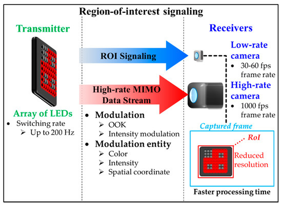
Figure 17.
Region-of-interest signaling.
3.2.1. RoI Signaling
Since the switching rate of the LED is defined to be flicker free (i.e., >100 Hz), the undersampled frequency shift on-off keying (UFSOOK) scheme was proposed for RoI signaling [66,67]. The principle of undersampling is based on having the camera’s sampling rate (i.e., FR) to be lower than Rs of the TX [5,68]. At the RX end, the differentiation between bits ‘1’ and ‘0’ is based on the difference of the frequency of the transmitted light pulse as in FSK. The encoding is illustrated in Figure 18. The decoding is performed based on a series of several adjacent samples. UFSOOK allows the use of both RS and GS mechanisms. This compatibility of two shutter mechanisms is the key for practical UFSOOK.
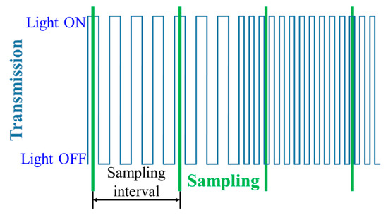
Figure 18.
UFSOOK encoding of a logic “0 1” bit pattern.
An enhanced version of the UFSOOK modulation was reported with the encoding performed on the phase shift rather than the frequency. It is known as undersampled phase shift on-off keying (UPSOOK) [68,69]. UPSOOK offers improved transmission efficiency of 1 bit/frame/LED, compared with only 0.5 bit/frame/LED for UFSOOK [68]. In [66], it was reported that the UPSOOK with dual LEDs with a designated mapping and framing method offers a data rate of 150 b/s over a transmission link span of longer than 10 m. Alternatively, undersampling for the low-rate data stream can also be performed spatially using a spatial modulation scheme, i.e., spatial 2-phase shift keying (S2-PSK), which was submitted to TG7m [14,64]. The capability of S2-PSK to demodulate with random sampling allows it to be used with time-variant frame rate cameras.
3.2.2. High Rate MIMO Data Stream
There are two proposed schemes for a high-rate MIMO in RoI-S, i.e., the twinkle variable pulse position modulation (VPPM) and hybrid spatial phase shift keying (HS-PSK) [5,67,70]. The former is a combination of UFSOOK and VPPM, wherein VPPM is achieved by changing the duty cycle of high rate pulses. The low-frequency UFSOOK signal is the amplitude envelope of the high-rate data signal, which is used for intensity modulation of the LED. The term “twinkle” in the twinkle VPPM stems from the LED lights being perceived as flashing rapidly on the RX [67]. On the other hand, HS-PSK is a combination of both S2-PSK and dimmable spatial multiple-PSK (DSM-PSK). Comparable to the twinkle VPPM, the amplitude modulated signal overlaps the S2-PSK signals with that of generated by DSM-PSK (i.e., multiple VPPM signals with delays). DSM-PSK is also considered for the NIR at a wavelength of 850 nm [67].
3.2.3. Compatible Encoding Scheme in the Time Domain
A study adopted a multiple frame rate encoding scheme for OCC that enables data transmission through different shutter speeds, sampling rates, as well as resolutions and distances [71]. This scheme encodes a special data packet on the TX that transmits both data and clock information. In case of a frame rate drop on the receiver camera, the error can later be corrected using external codes [71].
3.3. Hybrid Camera-PD Modulation
A hybrid camera-PD optical communication known as optical communication image sensor (OCI) has been proposed. The OCI employs an LED, camera and PD to provide a substantially improved response to light intensity variation compared with conventional imaging pixels [5,35,72,73]. In OCI, the detection of the light source from the image cells is performed prior to establishing a communication link and activating the PD cells. In addition, the detection of RoI is required; however, there is no RoI signaling and therefore a computer vision-based RoI algorithm is required. Figure 19 illustrates the operation, where a transmission range of 100 m was experimentally demonstrated. This range is considered exceptionally large for OCC and could provide a huge bandwidth of up to 10 MHz due to the use of PD cells [5,72]. Unfortunately, the hybrid camera-PD concept is not applicable to mobile devices in general, since OCI is still at the prototype stage at the time of writing and is not widely available. The advantage of OCI is the provision of a significantly higher SNR for real-time communications in both V2V and V2I outdoor OCC applications [72]. OCI is also envisioned for future indoor LiFi since it offers the benefit of spatial separation between OCC and VLC, while satisfying the 5G data rate requirement [5,14].
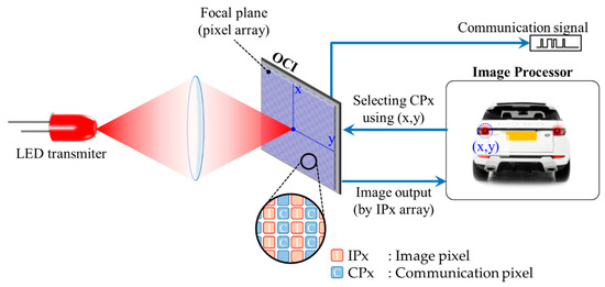
Figure 19.
Basic operation of IS-OWC system.
3.4. Rolling-Shutter-Based OCC
In order to increase the data throughput, a dedicated IS with a built-in PD (i.e., PIN) array was proposed in [59]. It is too complex to fabricate and not commercially available yet. However, by adopting the RS effect of a CMOS-based IS, it is possible to increase the data rate of OCC [5,24,74,75]. The RS-based OCC is the second commonly used scheme following NSM, since the implementation is practical on any CMOS-based cameras widely available. Moreover, the RS is also termed a RS patterning demodulation due to the focus on the demodulation [76]. Figure 20 shows the RS process where the data is sampled sequentially by the pixel rows. In RS, the sampling rate is the product of FR and the number of pixel rows (i.e., vertical resolution). For example, with a 30-fps camera having a resolution of FHD (1920 × 1080 pixels), the RS samples each image row, thus yielding 30 × 1080 samples on each frame. This leads to an effective rate of 32.4 Ksps. Therefore, it is obvious that in RS, the effective data rate depends on both the number of image rows (i.e., the camera’s vertical resolution) and FR. Note that in RS, the sampling rate of the LED TXs could be 1 KHz or higher.
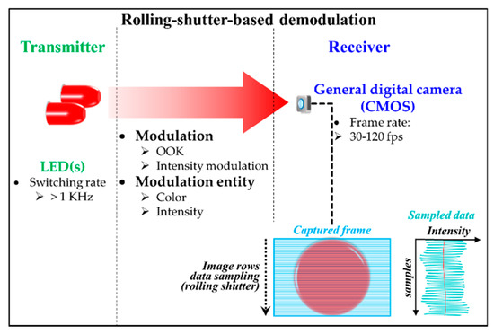
Figure 20.
RS-based demodulation process.
The width of different light intensity bands in the capture frame is proportional to the symbol rate of the LED TXs and the exposure period of the camera [17]. Adjusting the TX frequency affects the width of the captured light intensity bands as illustrated in Figure 21.
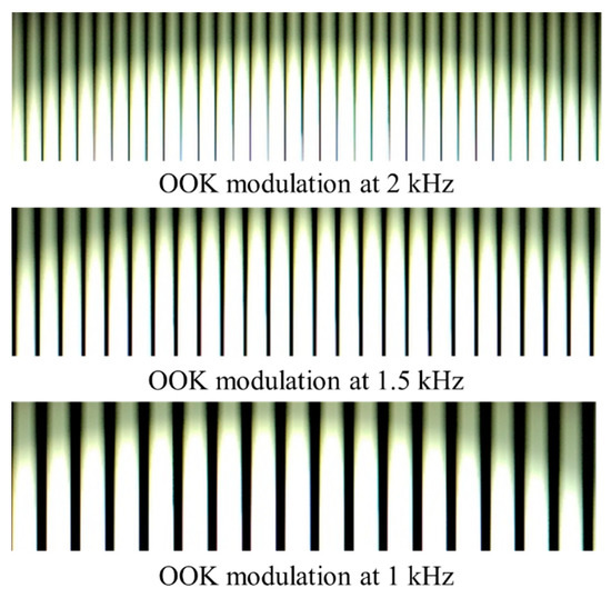
Figure 21.
Captured frames of OOK modulation with different frequencies.
With respect to the operation of the CMOS-based camera, the number of samples (i.e., pixel rows) acquired from the captured image of the light source in RS is given as [5]:
where denotes the image width (i.e., horizontal resolution) and is the normalized length (i.e., the diameter) of the light source along the width of the image sensor. indicates the distance between the light source (TX) and the camera (RX). The number of samples acquired from an image determines the amount of information that an image can capture in RS.
In RS, however, we have the following issues: (i) the blooming effect, which is the difference of light intensity between the area around the light source and the remaining frame area [23,74,77,78] and (ii) demodulation of the bright and dark fringes, which is challenging, due to its high data fluctuation and a large variation in the extinction ratio (ER), i.e., a significant blooming effect, see Figure 22. To mitigate the blooming effect, a suitable threshold scheme is required to level out the intensity across the captured frames so that an accurate binary threshold can be applied in order to demodulate the captured bit stream [74,79]. There are a number of image processing-based threshold schemes including 3rd order polynomial curve fitting, the iterative method [80], and quick adaptive method [81].
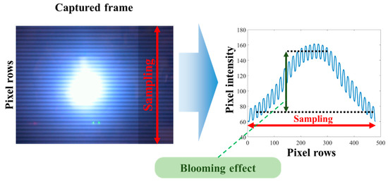
Figure 22.
Blooming effect on RS-OCC.
The quick adaptive thresholding utilizes a moving average calculation of grayscale values of pixels across the image rows [79,81]. The binary threshold is then set at the center row of the moving average results. The iterative method, on the other hand, divides the image rows into 24 sections and then applies iterative operation within each section. The iterative operation determines an initial grayscale value per each section and then divides the section into two subsets prior to averaging using addition and division by 2. Thus, it yields the ultimate grayscale values that are employed in the binary thresholding scheme [79].
These binary thresholding schemes were investigated for the RS in [79]. Note that they were implemented at the post-processing phase following image capturing. It was shown that the iterative and quick adaptive threshold schemes were able to reduce the processing time by 97% and 6%, respectively, when compared with [75].
In [79], it was shown that the adaptive scheme offered the lowest bit error rate (BER) performance compared with the other two but at the cost of increased processing time (i.e., 7 ms). The 3rd order polynomial curve fitting offers the least processing time (i.e., 0.95 ms) for the same image processing hardware [79]. The variations of n-th order polynomial curve fitting and the iterative schemes are preferable in most RS-OCCs due to their lower processing times and less complex implementation [23,74,76,77,82].
It should be noted that the RS-based OCC has more limited transmission distance compared with the RoI-S, due to the dependence on the requirement that the TX needs to be captured by whole pixel rows [83]. The transmission data rate can be increased using a 2D LED array (i.e., spatial division multiplexing) [56]. However, decoding the captured 2D RS pattern using a CMOS IS-based camera is a challenging task due to the merger of the RS pattern produced by different LEDs in the array. Hence, there is a need for advanced signal processing in order to separate these patterns. It is important to note that decoding of the 2D RS pattern with reduced offset tolerance and flexibility requires capturing lights from all LEDs using the IS [82].
3.5. Performance Comparison of Modulation Schemes
NSM-based OCC schemes are mostly intended for short-range communications, i.e., several meters with a data rate of Kbps to Mbps. The RoI-S provides improved efficiency in image processing and thus yields higher data rates of at least tens of Kbps for use in outdoor applications such as V2V and V2I communications. In addition, an OCI sensor provides an enhanced version of RoI-S with a novel IS, which is a hybrid between IS and PD, thus potentially increasing the data rate up to Gbps for future applications similar to VLC. Finally, RS-based schemes utilize the inherent RS properties of the IS to multiply the sampling rate based on the number of pixel rows. Thus, RS is intended for indoor applications and can also comply with LED-based lighting as TXs. In this regard, RS yields a data rate of up to tens of Kbps. Table 3 lists a concise performance comparison of representative OCC schemes.
Table 3.
Performance comparison of representative OCC scheme.
OCI exhibits the highest data rate of 55 Mbps due to its higher sampling rate by using PD-based RXs (communication cells) [35]. It is interesting to note that both RoI-S and high-rate NSM offer a longer transmission distance of up to 30 m, which is evidently suitable for long-range V2V applications [60,64]. CeilingTalk provides the longest RS-OCC transmission distance of 5 m at the cost of a lower data rate of 1 Kbps due to the implementation of systematic raptor coding in multiple LED-based TXs [84].
4. Mobility, Coverage, and Interference
As discussed in previous sections, the low data rate of OCC (i.e., due to the limitations of the camera) is the main issue in applications where there are demands for higher transmission rates. However, OCC can be conceived as an affordable and viable short-range transmission technology in the emerging field of IoT, where a range of information from different sources can be transmitted and captured in a cost-effective manner. In other words, OCC is best suited to ubiquitous, low-rate tolerable and license-free data communications rather than conventional high-speed data transmission systems. For OCC to evolve further, several important issues need to be resolved including mobility, coverage and interference. Recently, extensive studies have been focused on addressing these issues. Some mitigation techniques are elaborated in this section.
4.1. Mobility and Coverage
Both mobility and coverage are important in OCC since mobile devices are rarely static in indoor and outdoor environments. Seemingly, a high-speed camera RX is a prerequisite to solve these issues [35,60,72]. The mobility issue is more pronounced in OCC-based V2V and V2I communications. A number of studies have shown that the performance of OCC with no high-speed camera can be enhanced [17,35,78,85,86,87]. To support user mobility, tracking the RX’s position is essential in mobile environments. In [78], a tracking scheme based on the region-grow algorithm for the fixed column matrix selection technique was reported. However, there are still a number of issues in this scheme: (i) captured images may not have the TXs with the user mobility; (ii) high computational complexity; (iii) system performance being affected by the link span between the TX and the mobile RX due to light intensity fluctuation; (iv) inter-symbol interference (ISI), i.e., each row of pixels suffers more from the neighboring pixels induced interference, compared with stationary OCCs.
Although mobility can involve the movement of both the TX and the RX, the mobility in OCC studies is largely evaluated from the camera perspective [17,78,86]. In this approach, the movement is calculated from the captured frames as well as the orientation and acceleration data provision from additional sensors in smartphone-based OCC systems. A straightforward approach was proposed through an asynchronous unidirectional scheme by employing an oversampling technique to sample more frames at the RX [85]. It is termed asynchronous since there is no uplink channel for synchronization. Note that a data-shower method without an uplink channel is based on this approach.
An enhanced RS-based OCC is proposed to mitigate signal degradation caused by translational and rotational motions [88]. The solutions are Row Grayscale Redistribution (RGR) scheme and Differential Grayscale Packet Selection (DGPS) scheme. These schemes work by redistributing the varying intensity (in grayscale values) between neighboring pixel rows to improve the demodulation of the binary thresholding employed in the RS-based OCC [88]. The study proved that these schemes can correctly identify the data packet captured at 100 cm at a data rate of 1.51 Kbit/s, while being under the edge-to-edge translational motion and random rotational motion.
The oversampling method has an optimum number of oversampling defined by Equation (15) [85], which provides redundant frames during data capturing as illustrated in Figure 23. With the RX having redundant frames for the same bit, it selects the best frame with less degradation in the image quality.
where pps denotes the number of pulses per second (i.e., TX switching rate) and k is a constant indicating an extra frame captured beyond the number of transmitted frames. (k − 1) is the number of transmitted pulses, which is also equal to the captured frame. For example, in Equation (15), if pps is set to 667, then the minimum fps of the camera should be at least 1000.
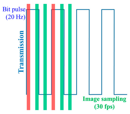
Figure 23.
Selecting two good frames among three adjacent captured frames.
Most OCC schemes are based on the LOS transmission mode due to the inherent nature of photography. However, reflected lights (i.e., non-LOS (NLOS) link) can also be captured using a camera, although it is not possible for RS-based OCC requiring only the image rows [44]. In [76], a unique NLOS OCC system for an indoor environment was investigated in [76]. The blooming effect [75] was mitigated using a background compensation algorithm combined with Bradley adaptive thresholding. Note that the blooming mitigation scheme can only work well when the TX is located at the center of captured images at the RX. The proposed NLOS OCC link achieved a total transmission distance of 1.5 m. Assuming that the transmission of each independent frame instead of a complete video stream with a series of images was performed, the data rates (the net data per frame) were approximately 96 and 172 bits/frame over the link spans of 1.5 and 0.40 m, respectively. In [89], to avoid the blooming effect, a dynamic column matrix selection algorithm matrix with a high extinction-ratio was proposed for OCC with mobility, achieving a data throughput of 1.08 Kbps. The experimental results showed that the link performance degraded when increasing both the transmission span and the user’s speed.
Another approach to address both the OCC coverage and mobility was reported, which used a wide RX orientation (WRO) for LOS and NLOS links simultaneously, as shown in Figure 24 [86]. WRO was proposed along with the design of the TX in order to distribute the illumination equally over a 120° irradiance angle, thus providing a wider coverage compared with existing OCC systems, albeit with a tradeoff in distance. Mobility is supported by utilizing a short exposure time, which successfully mitigated the need for the static RX. An adaptive blooming mitigation algorithm was employed to provide robust blooming mitigation for both LOS and NLOS based OCC systems [86].
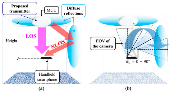
Figure 24.
Wide RX orientation scheme: (a) providing both LOS and NLOS communication links; (b) wide RX orientation.
The WRO scheme provides a free orientation of 90°, confirmed on a small-scale indoor testbed. It provides maximum transmission distances of up to 50 and 141 cm for LOS and NLOS, respectively and a data rate of 6.72 kbps. The scheme was omnidirectional, i.e., reflections from all walls within the room, and the mobility was achieved by means of a handheld RX, which was not strictly static even under a hand movement of up to 0.30 m/s. Similarly, higher mobility was further evaluated in the LOS RS-based OCC link for up to 0.80 m/s [89].
4.2. Interference Mitigation
Another performance enhancement feature of OCC is the interference mitigation capability due to the versatility of the camera for capturing light over a wide range spectrum. In OCC, one of the important interferences observed in the captured image is adjacent TXs induced inter-pixel interference (IPI) [17,22]. IPI could also be due to improper focusing when capturing flickering lights [22]. In general, cameras’ autofocusing feature is used prior to capturing the image [29]. The proposed IAC scheme includes dedicated illumination LEDs (i.e., TX) to mitigate the interference by providing fixed references for focusing for the camera [5,22]. Most cameras have automatic focus and light metering functionalities. Since OCC utilizes flickering LEDs, these flickers might confuse the camera’s automatic focusing and light-metering function. The illumination LEDs are thus kept always on (no flickering) to serve as fixed references for auto focusing and light metering in the camera. As illustrated in Figure 25, IAC successfully minimizes the corona/blooming (inter-pixel interferences between the adjacent LEDs) around LEDs with higher accurate color demodulation.
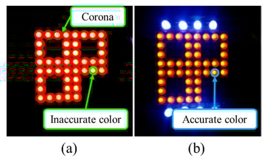
Figure 25.
Camera capture frame of IAC: (a) corona/blooming causing inter-pixel interference; (b) correct focus and accurate color interpretation [22].
Alternately, the IPI can be mitigated by using visual MIMO, specifically utilizing an image processing technique to extract the specific RoI prior to demodulation as illustrated in Figure 26 [17]. RoI is extracted by detecting the difference in intensity between the TXs and the background lights. It is true that visual MIMO is a throughput enhancement scheme in OCC. However, since the camera utilizes 2D spatial information, the visual MIMO can also be employed to classify and separate the transmitter lights (LEDs) and the interfering lights spatially through the captured frames. Therefore, providing an interference mitigation. Focus is indeed one of the major causes for interferences in a camera-based receiver, the solution of which is provided by IAC [22].
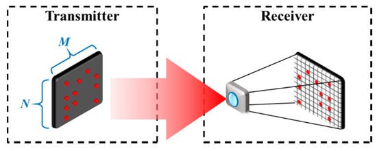
Figure 26.
A visual MIMO scheme.
In addition, a tracking functionality is employed in visual MIMO to detect the movement of the TX, which is observable between frames.
Since OCC operation is generally bounded by both the LOS path and the limitations of cameras, there are several issues that need addressing: directionality, focusing, alignment and distance. In [90], a pixelated MIMO scheme with a TX (an array of LEDs) fitted with a collimating lens was experimentally investigated for transmission in the angular domain rather than in the space domain. A series of time-varying coded (i.e., Raptor code) images were captured and decoded using a camera, which was focused at infinity, thus achieving a throughput of 30 bit/frame at a link span of 1 m. In addition, this scheme is robust against misalignment, camera focus and orientation.
It is evident that additional optical filters can be used to reduce the interference, which resides outside the modulated color and intensity of the light [17,56]. However, including additional filters will make the camera bulky, therefore making the OCC system impractical. An alternative interference mitigation scheme would be to shorten the camera’s exposure time, thus capturing a reduced amount of light from surroundings, while focusing mainly on the light from the TXs [86,91].
In [91], as illustrated in Figure 27, an interference mitigation scheme was proposed for IR-based OCC (IOCC) operating at the NIR spectrum band, more specifically at a wavelength of 940 nm. Although all cameras can capture NIR lights, the IR-blocking filter attached to the IS reduces the sensitivity at the NIR light. In IOCC, it is customary that the IR blocking filter is replaced with a diffuser in order to increase its robustness for capturing from IR LEDs and thus reducing the interference from other sources [91].
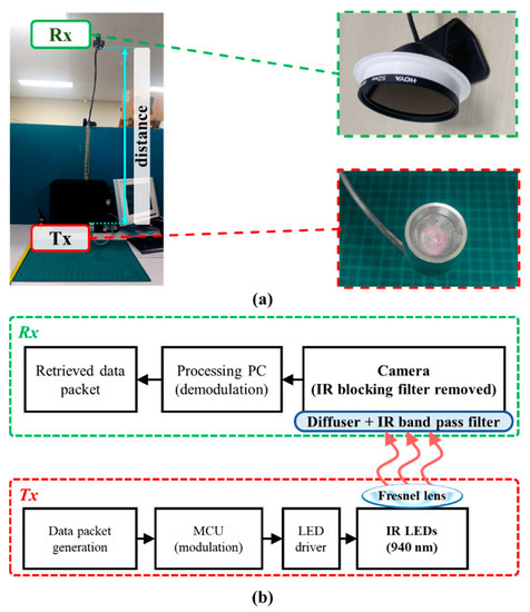
Figure 27.
IOCC: (a) experiment setup; (b) block diagram [91].
In OCC, IOCC was used as an uplink to provide a data rate of 6.72 Kbps over a link distance of 100 cm using IR LEDs with a total rated transmit power of 600 mW. Note that the achieved transmission distance is relatively longer compared with other RS-OCC schemes, due mainly to the effectiveness of mitigating the visible light induced interference. Note that in daytime outdoor applications, sunlight is considered the main interference for OCC schemes [35]. The use of the RoI technique (Visual MIMO) is mostly utilized in outdoor OCC schemes. The 2D captured images from the camera are effective to classify and separate the TXs spatially from the sunlight, thus improving the SNR [17,35]. The employment of additional polarizer would further improve the signal intensity in outdoor OCC applications, especially during daytime. Alternatively, outdoor OCC applications at night can be provided using an NIR light TX such as IOCC. It is applicable at night since NIR is unobtrusive to the human eyes and there is no sunlight that emits strong IR interference.
In addition, moving transmitters, generally in vehicular outdoor OCCs, present a unique interference of overlapping LEDs. The solution was proposed by tracking the movement of LEDs on each successive frame [92]. To separate the overlapping LEDs, the proposed method uses a series of consecutive frames as the input to track the movement of each LED based on their centroids (center of circle), as illustrated in Figure 28.
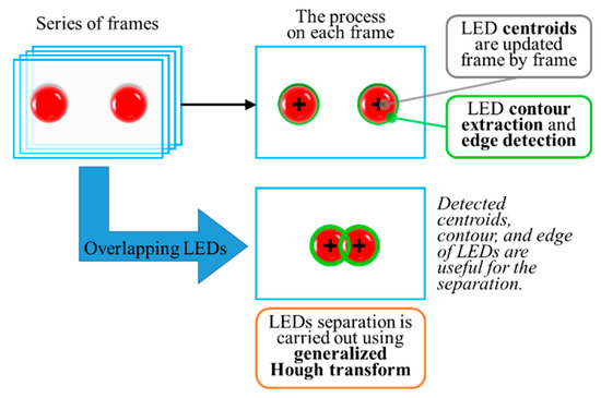
Figure 28.
Detection algorithm for overlapping LEDs [92].
5. Applications
OCC is deemed pragmatic due to the use of existing camera-based RXs that are widely available in smart devices. This versatility of the camera-based RX allows OCC for a range of applications in indoor and outdoor environments [25]. As outlined in the IEEE 802.15.7m services, various OCC applications are supported by PHY IV, V, and VI [14] for RoI-S, RS OCC, and NSM OCC, respectively.
5.1. Indoor Schemes
Indoor OCC schemes are the most prominent, as the majority of the intended applications among the use cases listed in the standardization are for indoor environments [25]. The use cases for indoor schemes include 2D LED color code [43,51,52,55], D2D as well as relay applications [37,38], digital signage [12,52,93], exhibition or store services [23,49,84,94,95] and in-flight services [49,52]. A combined version of these use cases is proposed for a more complex system such as smart factories, smart offices, and smart homes as part of the 4th Industrial Revolution solutions [25]. Several applications of OCC are described in this section to highlight the versatility of indoor OCC systems.
An OCC combined with motion detection was proposed in the framework of motion over camera. Figure 29 shows its concept [96]. The main principle behind this concept is based on the nature of image capturing at the RX, where the differences between adjacent frames can be used to detect the object motion, such as a pointing finger. The motion detection works in conjunction with the OCC through RoI selection, which can further be enhanced using a highly accurate NN-based motion detection scheme [97]. Note that the motion detection scheme is envisioned as an additional control function in OCC for use in smart homes and offices.
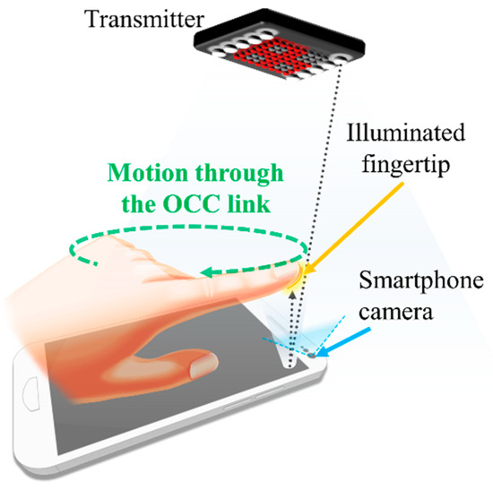
Figure 29.
A motion over camera scheme.
While most OCC studies have focused on unidirectional links, a bidirectional OCC utilizing RS was proposed with the camera-based RX for the uplink and the solar-cell-based RX for the downlink for IoT applications [98]. Note that the solar cell was used for a low-light requirement (i.e., as low as 100 lux of illuminance) for the downlink.
One of the most attractive OCC applications can be in D2D communications employing NSM [37,38,43]. In [38], illustrated in Figure 30, a smartphone VLC (SVLC) link employing a camera-based RX for short-range D2D communications was investigate. In this scheme, the RX captured the data from the screen of the TX and used a robust algorithm for detection. It applied projective transformation to accurately eliminate perspective distortions caused by the displacement of the devices with a 98% success rate. Similar to a dynamic 2D barcode, SVLC offers the possibility of transferring a significant amount of data by simply displaying it on the screen of a smart device. A data rate of 112.5 Kbps was achieved with only single-color modulation. SVLC has the potential of delivering a higher data rate of ~300 Kbps using RGB-based modulation. Despite its limited transmission distance of 15 cm, SVLC is preferable for D2D based financial transactions.
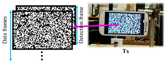
Figure 30.
A screen-based TX for SVLC [38].
An interesting smartphone-based scheme for D2D using NSM was proposed in [37], which used shape modulation to increase the data being modulated on each frame. Due to the high-density modulation on each frame, the achieved data rate was 2.66 Mbps at a transmission distance of 20 cm. Note that there is a tradeoff between the distance and the data rate, i.e., increasing the distance to 200 cm results in reduced data rate of 15.38 bps [93]. The scheme was designed to support the uplink transmission of a more complex OCC system, such as exhibition service or digital signage. The system is robust with an uplink failure rate of 10% [93,94].
In recent years, we have seen a growing level of interest in indoor positioning systems (IPSs). Currently, there are a number of IPSs such as radio frequency identification (RFID), ultra-wideband (UWB), and Wi-Fi [99,100,101]. However, these schemes suffer from RF electromagnetic interference and are costly. Both camera and PD can be used as the RX to detect intensity modulated light signals from LEDs. OCC-based IPSs have extensively been investigated for IoT applications. The OCC-based IPS for 2D and 3D positioning offers a number of advantages including high positioning accuracy (i.e., less than centimeters), license-free, no RF electromagnetic interference and low cost, since it uses the 2D information from the camera-based RX [68,95,102,103,104,105,106,107,108,109]. The OCC based positioning scheme is also deemed more practical since it can be implemented directly on the smartphones’ front cameras [105,107].
In the camera-based IPS, the RX’s position is determined based on the coordinates of LEDs and the captured image [14,15,16]. There are various algorithms for implementing IPS in OCC, which are classified into two categories based on the reference for positioning, see Figure 31. The illumination LEDs broadcast the references in the form of fixed coordinates relative to the dimension of the room/indoor space [105]. In the first IPS scheme, the smartphone camera acting as the user determines its own position based on the references set by the illumination LEDs. In the second type of IPS scheme, a camera is used as the reference, which actively looks for moving users to perform localization for each user [91,104].
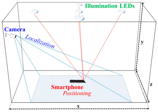
Figure 31.
Indoor positioning schemes for OCC.
The most popular localization algorithm adopted in IPS is the angle-of-arrival (AOA), which calculates the user’s position based on the projected lights from three or more LED TXs [11,102,105]. The AOA is a highly regarded IPS scheme in OCC, since it calculates both 3D position and the orientation of the camera. The optical AOA is commonly employed in OCC with a minimum of three TXs [105].
Among some IPS schemes, a dual-camera implementation was performed for improved accuracy, including the NIR medium that is considered safer to human eyes [91,104,106,110]. Machine learning has also been widely used to solve a range of problems in various applications such as data mining, pattern recognition, medical imaging, artificial intelligence, etc. In addition, NN is utilized to increase the accuracy of single-camera positioning by training the variants of pitch, roll, and yaw at the coordinate of the camera [95]. In [111], an OCC based IPS using NN was reported, where LEDs were grouped into blocks and the block coordinate was encoded on a single LED per block. A camera was used to decode the block coordinate to estimate the RX’s position using a trained back propagation NN. The experimental results showed that the mean positioning error, which is defined as the distance difference between the reference and estimated points, was 1.4 cm.
Philips Lighting launched an OCC-based IPS, which works in conjunction with Bluetooth low energy concept [112]. It showed the practicality of OCC as a complementary wireless IPS to be adopted in IoT and more specifically in indoor environments for commercial purposes. It should be noted that the OCC solution [113] cannot be implemented for long period usage similar to wireless sensor network since the average power consumption for OCC capable devices is approximately 3.5 W [113,114].
5.2. Outdoor Schemes
The main outdoor OCC applications are in smart cities for V2V, V2I, and underwater and seaside communications [5,14,25,115]. In V2V and V2I communications, spatial separation is the key advantage of an IS-based RX, as shown in Figure 32 [35,60,64,72,87,116]. Since either the TX or the RX are moving in outdoor environments, most popular modulation schemes for OCC are high-rate NSM, RoI-S, and hybrid camera-PD utilizing OCI sensors [35]. RoI image post-processing is predominantly utilized in outdoor OCC schemes to separate the TXs from severe light interference and noise, such as sunlight, thus improving the signal to noise and interference ratio.
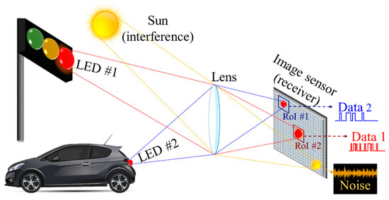
Figure 32.
Spatial separation of multiple sources using an image sensor.
The flickering of the LED-based TXs in both V2V and V2I communications is regulated to be imperceptible to human eyes. Therefore, the camera’s FR must be higher than 100 fps [60]. However, since high-speed and high-cost cameras are not used in vehicles, an OCI sensor is an important breakthrough in OCC for vehicular applications as mentioned previously in Section 3.3. OCI offers the dual benefits of spatial separation of the camera and the higher bandwidth of the PD-based RX, thus offering a practical data rate of 10–55 Mbps in vehicular applications [35,60]. On the other hand, relay-based communications are also investigated for outdoor OCC V2V applications. The relay is especially important between vehicles because it works as a complementary positioning system since the global positioning system (GPS) is inaccessible when vehicles are passing through tunnels [60,117]. It is worth mentioning that the OCC-based V2V and V2I systems require a robust tracking algorithm to identify RoI for the moving TX, while minimizing the amount of light interference in outdoor environments [118,119].
It is worth noting that under abrupt movements in outdoor vehicular applications, LED blurriness occurs due to lens misfocus that affects OCC transmission quality. A robust vehicular OCC system was proposed to address the issues [87]. It was evaluated in simulations, employing two novel algorithms, i.e., average greyscale ratio (AGR) and gradient radial inwardness (GRI), to decode the OCC transmission even when the captured LED transmitters appear blurry. The simulation results exhibited a robust transmission for decoding the OCC transmission at a BER rate of lower than 10−3, up to a distance of 60 m [87].
Underwater and seaside communications are also envisioned within the OCC standardization activity; however, further studies need to be conducted to investigate their full potentials [25,115,120]. In [115], an initial experimental investigation of an OCC link with a camera-based RX compared with the PD-based VLC was reported. In underwater environments with high degrees of absorption and scattering, the visibility of LEDs is not significantly affected. Thus, the camera can capture the transmitting light sources over longer distances compared with the PD-based RXs. A transmission distance of 1 m was achieved at a data rate of ~100 bps with a considerable limitation of the data rate due to a low camera frame rate of 30 fps [115].
6. Potential and Challenges
6.1. Potential Developments of Optical Camera Communication
Based on what has been reported in the literature on OCC, it is clear that the use of camera-based RXs makes communication much more versatile as a complementary wireless technology to existing RF-based wireless solutions. This section of the paper elaborates on several potential developments that would bring about further advancements of OCC within the OWC community.
6.1.1. Camera Hardware Advancements
Camera frame rates are projected to increase in the near future, owing to recent advancements in the IS nanotechnology [8,11,14,121]. Additionally, the camera resolution is also progressively increasing, according to demands on the market and the development of ISs in the smart devices industry. Moreover, the image quality of the miniaturized camera has become a top priority in most recent smartphone developments. These advancements will further drive the next generation OCC systems with a significantly faster and highly accurate camera-based RX.
Currently, research focus is placed on increasing the camera frame rate by allocating a higher storage speed within the camera sensors, employing a faster image processor and miniaturizing the size of a high-speed IS for use in mobile devices [13,61,122,123,124]. In the next decade, cameras with frame rates of thousands of fps in mobile devices are expected to be available in the market. The existing OCI hybrid sensor is also an excellent potential candidate for the RX in OCC-based V2V and V2I communications, offering a data rate of Gbps with a transmission distance of up to hundreds of meters in the near future [35,60].
On the other hand, the NSM-based OCC has an unresolved drawback of perceptible flickering of the TX, which can be mitigated by using higher speed cameras. The perceptible flickering is caused by a switching/refresh rate that is less than 100 Hz, due to the limited camera frame rate of 200 fps or lower [17,49,125]. The perceptible flicker below the flicker-fusion threshold of human eyes (i.e., 100 Hz) introduces fatigue and is therefore considered unhealthy [62].
The future research directions of OCC are to increase the data transmission rate and transmission distance. It can be made possible with a higher frame rate camera (faster image processor) beyond 200 fps and higher image resolution (larger image sensor) beyond 3840 × 2160 pixels in mobile devices, especially smartphones.
6.1.2. Neural Network Assistance
The developments of cameras for use in smartphones and other mobile devices can also be in augmented reality (AR) and mixed reality (MR). In addition, the implementation of intelligent image processing using artificial intelligence (AI) (i.e., NN) has become a prominent method in smartphones, which will be supported by online services such as Google [126,127,128]. The NN performance has also been accelerated with the implementation of dedicated hardware within smartphones in the form of a neural processing unit (NPU) as was first implemented in Apple A11 bionic chip and then Huawei HiSilicon Kirin 970 [121,129,130]. The use of NPUs accelerates the processing speed for NN-based processing including AI-based image processing in smartphones.
The NN implementation has been shown to be beneficial in image processing and in data communications; furthermore, OCC relies on extensive image processing techniques [37,95,97,117]. NN and its complex form of deep/machine learning are mostly employed for pattern recognition [59]. It is worth noting that there are always synchronized patterns between the TX and the RX in a communications scheme, which can be identified by NN in a straightforward manner [37,117,131,132]. The future developments of OCC will strongly benefit from NN advancements in order to offer increased data rates, robustness in reception and improved accuracy of RoI definition. In addition, an invisible watermarking through OCC as introduced in [12] will also be improved by using NN at the RX for higher data rates and longer transmission spans.
6.1.3. Multiple Cameras Development
The availability of multiple cameras in recent smartphones over the last five years has also provided additional opportunities and benefits for OCC including several FOVs, different light sensitivities and different resolutions for the RX. These features will result in wider coverage area, increased range of sensitivity for various light spectra, higher image details, increased robustness against the noise and higher data rates in OCC systems.
A salient advantage of multiple-camera-based OCC is the image redundancy, i.e., multiple copies of the same captured image of the TX, which can be exploited to increase the data rate by timing the shutter of each camera. An exemplary concept is illustrated in Figure 33, where four cameras in a device with different FOVs are employed to capture the same TX. Let us assume that each camera has a frame rate of 60 fps, i.e., a total capture period of approximately 16.5 ms. It is elaborated visually through Figure 34. Provided that cameras have enough storage for capturing four frames in less than 16.5 ms, then the frame rate of the combined multiple cameras can be increased to up to 240 fps by applying a shutter delay of 4 ms between the cameras. Note that the image processor should also be capable of processing at 240 fps.
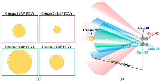
Figure 33.
Multiple camera OCC enhancement: (a) perspective of each camera; (b) multiple camera concept.
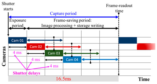
Figure 34.
Timed shutter for multiple-camera frame rates.
Multiple cameras also provide a potential benefit in the OCC research by elevating the 2D information to 3D. This is achieved by introducing distance/depth information through the stereoscopic vision of at least two cameras or more. Figure 35 shows that multiple copies of the same object are captured by the multiple cameras, thus providing different perspectives of the same captured object. Parallax is formed due to the difference between dml and dmr for the magenta LED relative to the lateral displacement between two cameras (). Similarly, parallax can also be formed from dyl and dyr. A distance estimation between camera and the LED can be produced by calibrating the parallax with the physical distance measurement.
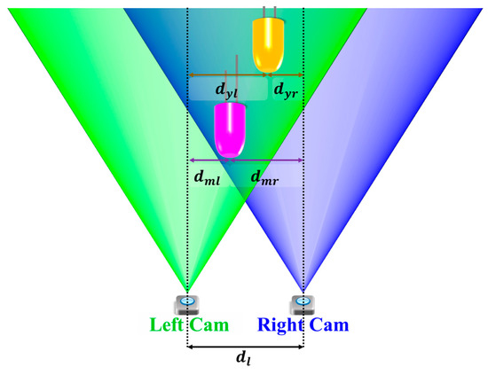
Figure 35.
Stereoscopic vision for distance measurement.
Future OCC can benefit from the availability of multiple camera and stereoscopic vision to calculate distances between the multiple TXs and multiple RXs (cameras). It is a huge potential to overcome several limitations in OCC, such as data rate and mobility.
6.1.4. Advanced Modulation and Communication Medium
Complex modulation schemes (including multi-level and multi-carrier) as well as WDM technologies can be used to increase the data throughput in OCC systems [90,133]. In addition, cameras with increased resolution and the development of more powerful image processing algorithms will enhance the efficiency and robustness of OCC [17,37].
Another potential of OCC lies in the broader communication media of IR and UV, since there are specific types of cameras that can operate in either IR or UV light [3]. IR has the advantage of being invisible to human eyes, therefore allowing higher transmission power with much reduced health hazard, compared with the visible light spectrum. It is ideal for nighttime operations, particularly for V2V and V2I applications [3]. On the other hand, the UV light has been used for long-distance outdoor communications (mainly for military applications), since it takes advantage of the scattering properties of the atmosphere, specifically the UV-C band, which is not present at the terrestrial zone below the atmosphere [134]. These specially designed OCCs utilizing either IR or UV as a medium have yet to be studied and are going to open a new horizon for co-existing with or complementing other wireless communication schemes.
6.1.5. Automated Indoor Navigation
Most of OCC studies have been focused on static cameras and an LOS communication link. However, the studies described in Section 4 and Section 5 have shown several possible implementations of OCC schemes with a dynamic camera and an NLOS link.
It is worth noting that there is potential development for OCC implementation in which the camera cannot look directly toward the light source while the RX also moves around continuously, namely automated indoor navigation. A high demand for automated guided vehicles (AGV), a robot for transporting goods, in industries has evolved a camera for the automatic navigation (line following) to transport storage items indoors. Unfortunately, the maintenance of the lines on the floor is not as convenient as maintaining constant illumination on the ceiling.
Moreover, AGV demands a more robust indoor positioning scheme which is currently dominated by RF-based solutions, such as WiFi and Bluetooth. A light-based positioning solution can be provided by using either a photodiode or the existing camera embedded on the AGV. The latter solution can be more efficient as it is provided by OCC, as illustrated in Figure 36. It is, however, not practical for the camera on AGV to face upward, even though the most common light source for TX would be the illumination on the ceiling. Therefore, the NLOS link benefits in OCC by receiving the signal from the diffused reflection on the walls or other objects.
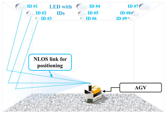
Figure 36.
AGV potential indoor positioning scheme.
6.1.6. Beyond 5G
There is a certain massive development of wireless technologies beyond the current 5G wireless networks [19]. OCC, utilizing both the visible light and NIR light, becomes a part of future communication system envisioned in 5G and 6G standards. It is due to the fact that frequencies from 100 GHz to 3 THz, including visible light and NIR, are considered promising communication bands for the next gen wireless communication system [19]. In the wake of 5G implementation, 6G conception was formulated further to emphasize on increasing its massive bandwidth and massive interconnectivity among wireless devices, acting similar to massive relays. In order for this 6G vision to be realized, it is important to ensure various options and availability of wireless communication. OCC has a unique role in being a part of OWC for future communications beyond 5G and holds a potential for pragmatic wireless schemes since the users hold cameras in smartphone. On the other hand, unmanned aerial vehicles (UAVs) are also becoming an important part of 5G and IoT, and expected to play a crucial role in enabling more functional diversity for wireless communications [135]. It is worth noting that UAVs often have one or more cameras attached in order to see, record, evaluate, and communicate efficiently [135,136]. OCC applications within UAV therefore have potential for significant benefits beyond 5G.
6.2. Challenges
While witnessing great potential and future applications for OCC, there are a number of challenges that are not fully addressed or only partially studied [5,11,17], which need further investigations in order to make OCC a more practical wireless technology for emerging future applications within the context of smart societies.
6.2.1. Synchronization
The intrinsic principle of OCC operation is based mainly on a broadcasting topology with no feedback information being provided during transmission [16,17]. Synchronization is, therefore, a challenging issue that needs addressing for two main reasons: (i) sampling is carried out randomly in a camera, i.e., it can take place during any symbol of the transmitted signal, thus leading to an increased symbol error rate and (ii) different frame sampling periods (i.e., frame saving periods) for cameras. Table 4 shows a few examples of the frame rates for several cameras for the same FHD resolution and a frame rate of 30 fps.
Table 4.
Camera frame rate on several devices.
Figure 37 illustrates the implication of inconsistent frame sampling interval that is caused by different frame saving periods. The operation of these synchronization protocols depends on the IS characteristics. In addition, the synchronization complexity increases when the inconsistent refresh/switching rate is considered at the TX. Note that in addition to synchronization, color calibration is also mandatory on color modulation used in OCC since both cameras and the TX (LED/digital display) do not share the same calibrated color profile. Several OCC schemes have been proposed including keyframes and anchors, in order to alleviate the synchronization issue by employing fixed references for the color and frame boundaries [22,37,55]. It is worth noting, however, that further studies are required since channel modeling for OCC has not been extensively investigated.
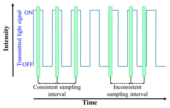
Figure 37.
Effects of frame rate inconsistency.
On the other hand, the RS OCC encounters interframe synchronization due to a considerable delay between the consecutive frames captured, depending on the frame-saving period for each frame [82]. It is an inconsistent period across different camera hardware, due to image processing and storage speed.
6.2.2. Data Rate Efficiency
As mentioned previously, the data rate can also be increased further. There are some noticeable solutions, e.g., a high-speed camera with a frame rate of beyond 1000 fps and a reduced resolution for a higher frame rate [36,60]. However, the commonly employed solution to increase the camera sampling rate is to utilize a RS mechanism in CMOS-based sensors, since it requires no hardware alteration. In [133], an NSM using shape modulation and 2D OFDM was proposed to increase the bit density per frame.
Image processing is part of OCC challenges relative to the nature of camera functionality itself for capturing pictures/photos. The image processing load increases linearly with the camera resolution, which is crucial to resolve details in the captured image [29]. In addition, the theoretical data rate of the OCC cannot be achieved, since not all pixels of the IS are being exposed to independent light sources. For example, for OCC with 64-RGB LEDs modulated with OOK at 30 bps and a camera with a resolution of 1920 × 1080 pixels and a frame rate of 60 fps at a short link span of 30 cm, a data rate of 5760 bit/s can be achieved. However, the theoretical limit of the data rate for this system is 1920 × 1080 × 8 × 60 × 3 bits for an 8-bit quantization. When the camera is employed solely for OCC, the efficiency of processing images requires further improvement. Several solutions were proposed either by reducing the resolution of the image to be captured [17,36] or utilizing the only parts of the image [38,74].
6.2.3. Camera Lens Distortion
The use of a lens in a camera with a focal length not matching to the size of the IS, introduces optical distortions in the captured image [137,138,139]. These distortions can be barrel, pincushion, and mustache distortions, as illustrated in Figure 38.
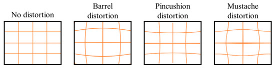
Figure 38.
Distortions caused by various lenses [140].
Barrel distortion occurs when a significantly wide FOV of the lens is compressed to fit on the image sensor, which is common in a shorter focal length (wide lenses), thus causing curved lines similar to a barrel. Pincushion distortion occurs when an FOV of the lens is much narrower than the size of the image sensor, which is common in a longer focal length (telescopic lenses). Mustache distortion is a combination of both barrel and pincushion distortion due to the lower quality of the lens build. These distortions are present in many cameras to a varying degree and require correction prior to the use in OCC [139,141]. Unfortunately, this distortion issue has not been investigated in existing OCC studies. It was largely circumvented via image cropping or idealized TX images positioned in the sensor area with no lens induced distortions [5,11,17]. Clearly, for the deployment of practical OCC schemes, it is required to address these distortions in the future. A multiple-camera setup can be used to mitigate the image distortion as it provides multiple perspectives of the images [138,139,142].
6.2.4. Flicker-Free Modulation Formats
Some modulation schemes, such as a low-rate NRZ OOK can result in flickering. For the flicker-free modulation, a number of schemes have been reported in the literature. RS-based OCC modulation schemes such as UPSOOK may be seen as dark and bright ribbons in large footprints. To address this problem, differential signaling should be adopted. That is, following frame subtraction, only dark or bright regions will remain under the assumption that the TX and the camera are synchronized in the frequency domain.
6.2.5. Higher Order Modulation Formats
Since vehicles move at a relatively high-speed in V2V communications, it is necessary that the transmitted packets are short and captured instantly at the RX, prior to the scene being changed significantly. Therefore, given that the data rate is fixed, high-order and multi-carrier modulation schemes can be employed to keep the packet size as short as possible, thus ensuring the received packets with a low probability of error.
7. Summary
Optical camera communications have the potential to provide a complementary solution to OWC by employing a highly versatile camera-based RX. OCC gains significant practical benefit over VLC due to the availability of camera in daily used smartphones without further hardware modifications on the RX side. This paper has presented a comprehensive survey on OCC, covering its current status as well as potential developments and challenges facing the OCC system. The state-of-the-art technologies for advanced cameras and image processing algorithms have been introduced rapidly for the past decade, which will surely expedite the full-fledged commercialization of high-rate OCCs.
Even with the current relatively low-rate OCCs, a range of attractive applications in the era of IoT are envisioned as a practical means of data communications in certain indoor and outdoor environments. Moreover, therefore, the potential of reliable, practical and cost-effective OCC schemes is yet to be unlocked in future research. This paper has provided a discourse on the current OCC status and future research directions in a timely manner, together with recent IEEE standardization activities.
Author Contributions
Conceptualization, W.A.C. and Y.H.C.; methodology, Y.H.C.; software, W.A.C.; validation, W.A.C., Y.H.C. and Z.G.; formal analysis, Y.H.C. and Z.G.; investigation, W.A.C. and N.B.H.; resources, W.A.C. and N.B.H.; data curation, W.A.C. and N.B.H.; writing—original draft preparation, W.A.C.; writing—review and editing, W.A.C., Y.H.C., and Z.G.; visualization, W.A.C.; supervision, Y.H.C. and Z.G.; project administration, Y.H.C.; funding acquisition, Y.H.C and W.A.C. All authors have read and agreed to the published version of the manuscript.
Funding
This research was funded by Basic Science Research Program through the National Research Foundation of Korea (NRF) funded by the Ministry of Education (2018R1D1A3B07049858) and The APC was funded by Telkom University.
Acknowledgments
This research was supported by Basic Science Research Program through the National Research Foundation of Korea (NRF) funded by the Ministry of Education (2018R1D1A3B07049858).
Conflicts of Interest
The authors declare no conflict of interest. The funders had no role in the design of the study; in the collection, analyses, or interpretation of data; in the writing of the manuscript, or in the decision to publish the results.
Appendix A
This appendix is intended to list all abbreviations and acronyms used throughout the paper.
Table A1.
List of abbreviations and acronyms.
Table A1.
List of abbreviations and acronyms.
| Acronym | Full Title |
|---|---|
| 2D | Two-dimension |
| 5G | Fifth generation wireless networks |
| A-QL | Asynchronous quick link |
| ACO-OFDM | Asymmetrically clipped optical OFDM |
| ADC | Analog-to-digital Converter |
| Adv | Advanced |
| AGC | Automatic gain Control |
| AI | Artificial intelligence |
| AR | Augmented reality |
| bps | Bits per second |
| C-OOK | Camera OOK |
| CFA | Color filter array |
| CM-FSK | Camera multiple frequency shift keying |
| CMOS | Complementary metal-oxide semiconductor |
| CoC | Circle of confusion |
| Comm | Communication |
| CSK | Color shift keying |
| DC-biased | Direct current-biased |
| DCO-OFDM | Direct current-biased optical OFDM |
| Dev | Development |
| DMT | Discrete multitone |
| eU-OFDM | Enhanced unipolar OFDM |
| ER | Extinction ratio |
| fps | Frames per second |
| FR | Frame rate |
| FHD | Full high definition |
| FOV | Field of view |
| FSO | Free space optics |
| Gbps | Gigabits per second |
| GPS | Global positioning system |
| HA-QL | Hidden asynchronous quick link |
| HDM | High density modulation |
| HS-PSK | Hybrid spatial phase shift keying |
| IAC | Illumination augmented OCC |
| IOCC | Infrared-based OCC |
| IoT | Internet-of-things |
| IPS | Indoor positioning system |
| IPU | image processing unit |
| IR | Infrared |
| IRC | Infrared communications |
| IS | Image sensor |
| ISC | Image sensor Communications |
| Kbps | Kilobits per second |
| LCD | Liquid crystal display |
| LED | Light-emitting diode |
| LED-ID | LED identification |
| LOS | Line of sight |
| Mbps | Megabits per second |
| MIMO | Multiple-input-multiple-output |
| MSE | Mean squared error |
| MR | Mixed reality |
| NIR | Near infrared |
| NLOS | Non line of sight |
| NN | Neural network |
| NSM | Nyquist sampling modulation |
| OCC | Optical camera communications |
| OFDM | Orthogonal frequency division multiplexing |
| OLED | Organic light-emitting diode |
| OOK | On-off Keying |
| OWC | Optical wireless communications |
| PD | Photodiode/photodetector |
| PHY | Physical |
| PPM | Pulse position modulation |
| PWM | Pulse width modulation |
| RGB | Red, green, and blue |
| RF | Radio frequency |
| RFID | RF identification |
| RoI | Region of Interest |
| RoI-S | RoI signaling |
| RPO-OFDM | Reverse polarity optical OFDM |
| RS | Rolling shutter |
| RS-OCC | Rolling-shutter-based OCC |
| RS-FSK | Rolling shutter frequency shift keying |
| RX | Receiver |
| S2-PSK | Spatial 2-phase shift keying |
| SNR | Signal-to-noise ratio |
| sps | Samples per second |
| SVLC | Smartphone VLC |
| TX | Transmitter |
| UAV | Unmanned Aerial Vehicle |
| UFSOOK | Undersampled frequency shift OOK |
| UPSOOK | Undersampled phase shift OOK |
| UV | Ultraviolet |
| UVC | UV communications |
| UWB | Ultra-wide band |
| V2I | Vehicle-to-infrastructure communications |
| V2V | Vehicle-to-vehicle communications |
| VLC | Visible Light communications |
| VPPM | Variable pulse position modulation |
| VTASC | Variable transparent amplitude shape code |
| Wi-Fi | Wireless fidelity |
| WRO | Wide receiver orientation |
References
- Paathak, P.H.; Feng, X.; Hu, P.; Mohapatra, P. Visible Light Communication, Networking, and Sensing: A Survey, Potential and Challenges. IEEE Commun. Surv. Tutor. 2015, 17, 2047–2077. [Google Scholar] [CrossRef]
- Ghassemlooy, Z.; Popoola, W.; Rajbhandari, S. Optical Wireless Communications; CRC Press: Boca Raton, FL, USA, 2013. [Google Scholar]
- Koonen, T. Indoor Optical Wireless Systems: Technology, Trends, and Applications. J. Lightwave Technol. 2018, 36, 1459–1467. [Google Scholar] [CrossRef]
- O’Brien, D. Optical wireless communications: Current status and future prospects. In Proceedings of the 2016 IEEE Photonics Society Summer Topical Meeting Series, Newport Beach, CA, USA, 11–13 July 2016. [Google Scholar]
- Nguyen, T.; Islam, A.; Hossan, M.T.; Jang, Y.M. Current Status and Performance Analysis of Optical Camera Communication Technologies for 5G Networks. IEEE Access 2017, 5, 4574–4594. [Google Scholar] [CrossRef]
- Arya, S.; Chung, Y.H. Non-line-of-sight Ultraviolet Communication with Receiver Diversity in Atmospheric Turbulence. IEEE Photonics Technol. Lett. 2018, 30, 895–898. [Google Scholar] [CrossRef]
- Ayyash, M.; Elgala, H.; Khreishah, A.; Little, T.; Shao, S.; Rahaim, M.; Schulz, D.; Hilt, J.; Freund, R. Coexistence of WiFi and LiFi toward 5G: Concepts, Opportunities, and Challenges. IEEE Commun. Mag. 2016, 54, 64–71. [Google Scholar] [CrossRef]
- Elgala, H.; Mesleh, R.; Haas, H. Indoor Optical Wireless Communication: Potential and State-of-the-art. IEEE Commun. Mag. 2011, 49, 56–62. [Google Scholar] [CrossRef]
- Ghassemlooy, Z.; Alves, L.N.; Zvanovec, S.; Khalighi, M.-A. Visible Light Communications: Theory and Applications; CRC Press: Boca Raton, FL, USA, 2017. [Google Scholar]
- Ghassemlooy, Z.; Popoola, W.O.; Tang, X.; Zvanovec, S.; Rajbhandar, S. Visible Light Communications—A Review. IEEE COMSOC MMTC Commun. Front. 2017, 12, 6–13. [Google Scholar]
- Saha, N.; Ifthekhar, M.; Shareef, N.; Le, T.; Jang, Y.M. Survey on optical camera communications: Challenges and opportunities. IET Optoelectron. 2015, 9, 172–183. [Google Scholar] [CrossRef]
- Le, N.T. Invisible watermarking optical camera communication and compatibility issues of IEEE 802.15.7r1 specification. Opt. Commun. 2017, 390, 144–155. [Google Scholar] [CrossRef]
- Haruta, T.; Nakajima, T.; Hashizume, J.; Umebayashi, T.; Takahashi, H.; Taniguchi, K.; Kuroda, M.; Sumihiro, H.; Enoki, K.; Yamasaki, T.; et al. 4.6 A 1/2.3inch 20Mpixel 3-layer stacked CMOS. In Proceedings of the IEEE International Solid-State Circuits Conference, San Fransisco, CA, USA, 5–9 February 2017. [Google Scholar]
- Nguyen, T.; Islam, A.; Yamazato, T.; Jang, Y.M. Technical Issues on IEEE 802.15.7m Image Sensor Communication Standardization. IEEE Commun. Mag. 2018, 56, 213–218. [Google Scholar] [CrossRef]
- IEEE. IEEE 802.15.7-2011—IEEE Standard for Local and Metropolitan Area Networks—Part 15.7: Short-Range Wireless Optical Communication Using Visible Light. IEEE Standards Association. 6 September 2011. Available online: https://standards.ieee.org/standard/802_15_7-2011.html (accessed on 23 October 2018).
- IEEE. IEEE 802.15 WPANTM 15.7 Maintenance: Short-Range Optical Wireless Communications Task Group (TG 7m). 23 October 2018. Available online: http://www.ieee802.org/15/pub/IEEE%20802_15%20WPAN%2015_7%20Revision1%20Task%20Group.htm (accessed on 23 October 2018).
- Le, N.T.; Hossain, M.A.; Jang, Y.M. A Survey of Design and Implementation for Optical Camera Communication. Signal Process. Image Commun. 2017, 53, 95–109. [Google Scholar] [CrossRef]
- Saeed, N.; Guo, S.; Park, K.-H.; Al-Naffouri, T.Y.; Alouini, M.-S. Optical camera communications: Survey, use cases, challenges, and future trends. Phys. Commun. 2019, 37, 100900. [Google Scholar] [CrossRef]
- Rappaport, T.S.; Xing, Y.; Kanhere, O.; Ju, S.; Madanayake, A.; Mandal, S.; Alkhateeb, A.; Trichopoulos, G.C. Wireless Communications and Applications Above 100 GHz: Opportunities and Challenges for 6G and Beyond. IEEE Access 2019, 7, 78729–78757. [Google Scholar] [CrossRef]
- Wikipedia. IEEE 802.15. Wikimedia Foundation, 19 September 2018. Available online: https://en.wikipedia.org/wiki/IEEE_802.15 (accessed on 20 October 2018).
- IEEE. IEEE 802.15 WPAN™ 15.7 Amendment—Optical Camera Communications Study Group (SG 7a). 23 October 2018. Available online: http://www.ieee802.org/15/pub/SG7a.html (accessed on 23 October 2018).
- Cahyadi, W.A.; Kim, Y.H.; Chung, Y.H.; Ahn, C.-J. Mobile Phone Camera-Based Indoor Visible Light Communications with Rotation Compensation. IEEE Photonics J. 2016, 8, 1–8. [Google Scholar] [CrossRef]
- Chow, C.W.; Chen, C.Y.; Chen, S.H. Visible light communication using mobile-phone camera with data rate higher than frame rate. Opt. Express 2015, 23, 26080–26085. [Google Scholar] [CrossRef] [PubMed]
- Danakis, C.; Afgani, M.; Povey, G.; Underwood, I.; Haas, H. Using a CMOS camera sensor for visible light communication. In Proceedings of the 2012 IEEE Globecom Workshops, Anaheim, CA, USA, 3–7 December 2012. [Google Scholar]
- Cha, J. IEEE 802 Optical Wireless Communication (IEEE 802 OWC Technology Trends and Use Cases). In Proceedings of the IEEE Blockchain Summit Korea, Seoul, Korea, 7–8 June 2018. [Google Scholar]
- Serafimovski, N.; Jungnickel, V.; Jang, Y.; Qiang, J. An Overview on High Speed Optical Wireless/Light Communication. 3 July 2017. Available online: https://mentor.ieee.org/802.11/dcn/17/11-17-0962-01-00lc-an-overview-on-high-speed-optical-wireless-light-communications.pdf (accessed on 14 March 2019).
- Jang, Y.M. IEEE 802.15 Documents: 15.7m Closing Report. 14 November 2018. Available online: https://mentor.ieee.org/802.15/dcn/18/15-18-0596-00-007a-15-7m-closing-report-nov-2018.pptx (accessed on 8 February 2019).
- IEEE. IEEE 802.15.7-2018—IEEE Draft Standard for Local and Metropolitan Area Networks—Part 15.7: Short-Range Optical Wireless Communications. 5 December 2018. Available online: https://standards.ieee.org/standard/802_15_7-2018.html (accessed on 12 February 2019).
- Gamal, A.E.; Eltoukhy, H. CMOS Image Sensors. IEEE Circuits Devices Mag. 2005, 21, 6–20. [Google Scholar] [CrossRef]
- Merritt, R. TSMC Goes Photon to Cloud; EE Times: San Jose, CA, USA, 2018. [Google Scholar]
- Celebi, M.E.; Lecca, M.; Smolka, B. Image Demosaicing. In Color Image and Video Enhancement; Springer International Publishing: Cham, Switzerland, 2015; pp. 13–54. [Google Scholar]
- Tanaka, M. Give Me Four: Residual Interpolation for Image Demosaicing and Upsampling; Tokyo Institute of Technology: Tokyo, Japan, 2018; Available online: http://www.ok.sc.e.titech.ac.jp/~mtanaka/research.html (accessed on 8 November 2018).
- Meroli, S. Stefano Meroli Lecture: CMOS vs CCD Pixel Sensor. 17 August 2005. Available online: Meroli.web.cern.ch/lecture_cmos_vs_ccd_pixel_sensor.html (accessed on 22 October 2018).
- Chen, Z.; Wang, X.; Pacheco, S.; Liang, R. Impact of CCD camera SNR on polarimetric accuracy. Appl. Opt. 2014, 53, 7649–7656. [Google Scholar] [CrossRef]
- Goto, Y.; Takai, I.; Yamazato, T.; Okada, H.; Fujii, T. A New Automotive VLC System Using Optical Communication Image Sensor. IEEE Photonics J. 2016, 8, 1–17. [Google Scholar] [CrossRef]
- Teli, S.; Chung, Y.H. Selective Capture based High-speed Optical Vehicular Signaling System. Signal Process. Image Commun. 2018, 68, 241–248. [Google Scholar] [CrossRef]
- Cahyadi, W.A.; Chung, Y.H. Smartphone Camera based Device-to-device Communication Using Neural Network Assisted High-density Modulation. Opt. Eng. 2018, 57, 096102. [Google Scholar] [CrossRef]
- Boubezari, R.; Minh, H.; Ghassemlooy, Z.; Bouridane, A. Smartphone Camera Based Visible Light Communication. J. Lightwave Technol. 2016, 34, 4121–4127. [Google Scholar] [CrossRef]
- QImaging. Rolling Shutter vs. Global Shutter: CCD and CMOS Sensor Architecture and Readout Modes. 2014. Available online: https://www.selectscience.net/application-notes/Rolling-Shutter-vs-Global-Shutter-CCD-and-CMOS-Sensor-Architecture-and-Readout-Modes/?artID=33351 (accessed on 21 March 2018).
- Do, T.-H.; Yoo, M. Performance Analysis of Visible Light Communication Using CMOS Sensors. Sensors 2016, 16, 309. [Google Scholar] [CrossRef] [PubMed]
- Shlomi Arnon, B.G. Visible Light Communication; Cambridge University Press: Cambridge, UK, 2015. [Google Scholar]
- National Instruments, Calculating Camera Sensor Resolution and Lens Focal Length. 15 February 2018. Available online: http://www.ni.com/product-documentation/54616/en/ (accessed on 6 November 2018).
- Cahyadi, W.A.; Kim, Y.H.; Chung, Y.H. Dual Camera based Split Shutter for High-rate and Long-distance Optical Camera Communications. Opt. Eng. 2016, 55, 110504. [Google Scholar] [CrossRef]
- Hassan, N.; Ghassemlooy, Z.; Zvanovec, S.; Luo, P.; Le-Minh, H. Non-line-of-sight 2 × N indoor optical camera communications. Appl. Opt. 2018, 57, 144–149. [Google Scholar] [CrossRef] [PubMed]
- Chau, J.C.; Little, T.D. Analysis of CMOS active pixel sensors as linear shift-invariant receivers. In Proceedings of the 2015 IEEE International Conference on Communication Workshop, London, UK, 8–12 June 2015. [Google Scholar]
- Hassan, N.B. Impact of Camera Lens Aperture and the Light Source Size on Optical Camera Communications. In Proceedings of the 11th International Symposium on Communication Systems, Networks & Digital Signal Processing (CSNDSP), Budapest, Hungary, 12–18 July 2018. [Google Scholar]
- Hossain, M.A.; Hong, C.H.; Ifthekhar, M.S.; Jang, Y.M. Mathematical modeling for calibrating illuminated image in image sensor communication. In Proceedings of the 2015 International Conference on Information and Communication Technology Convergence (ICTC), Jeju, Korea, 28–30 October 2015. [Google Scholar]
- Huynh-Thu, Q.; Ghanbari, M. Scope of validity of PSNR in image/video quality assessment. Electron. Lett. 2008, 44, 800–801. [Google Scholar] [CrossRef]
- Iizuka, N. CASIO Response to 15.7r1 CFA. March 2015. Available online: https://mentor.ieee.org/802.15/dcn/15/15-15-0173-01-007a-casioresponse-to-15-7r1-cfa.pdf (accessed on 24 January 2019).
- Perli, S.D.; Ahmed, N.; Katabi, D. PixNet: Interference-free wireless links using LCD-camera pairs. In Proceedings of the MobiCom ACM, New York, NY, USA, 20–24 September 2010. [Google Scholar]
- Hao, T.; Zhou, R.; Xing, G. COBRA: Color barcode streaming for smartphone system. In Proceedings of the MobiSys ACM, Ambleside, UK, 25–29 June 2012. [Google Scholar]
- Hu, W.; Gu, H.; Pu, Q. LightSync: Unsynchronized visual communication over screen-camera links. In Proceedings of the 19th Annual International Conference on Mobile Computing & Networking, New York, NY, USA, 30 September–4 October 2013. [Google Scholar]
- Nguyen, T.; Jang, Y.M. Novel 2D-sequential color code system employing Image Sensor Communications for Optical Wireless Communications. ICT Express 2016, 2, 57–62. [Google Scholar] [CrossRef]
- Hossain, M.A.; Lee, Y.T.; Lee, H.; Lyu, W.; Hong, C.H.; Nguyen, T.; Le, N.T.; Jang, Y.M. A Symbiotic Digital Signage system based on display to display communication. In Proceedings of the 2015 Seventh International Conference on Ubiquitous and Future Networks, Sapporo, Japan, 7–10 July 2015. [Google Scholar]
- Huang, W.; Tian, P.; Xu, Z. Design and implementation of a real-time CIMMIMO optical camera communication system. Opt. Express 2016, 24, 24567–24579. [Google Scholar] [CrossRef]
- Chen, S.H.; Chow, C. Color-filter-free WDM MIMO RGB-LED visible light communication system using mobile-phone camera. In Proceedings of the 2014 13th International Conference on Optical Communications and Networks (ICOCN), Suzhou, China, 9–10 November 2014. [Google Scholar]
- Chen, S.; Chow, C.W. Color-Shift Keying and Code-Division Multiple-Access Transmission for RGB-LED Visible Light Communications Using Mobile Phone Camera. IEEE Photonics J. 2014, 6, 1–6. [Google Scholar] [CrossRef]
- Basu, J.K.; Bhattacharyya, D.; Kim, T. Use of Artifical Neural Network in Pattern Recognition. Int. J. Softw. Eng. Appl. 2010, 4, 23–34. [Google Scholar]
- Yu, P.; Anastassopoulos, V.; Venetsanopoulos, A.N. Pattern classification and recognition based on morphology and neural networks. Can. J. Electr. Comput. Eng. 1992, 17, 58–64. [Google Scholar] [CrossRef]
- Yamazato, T.; Takai, I.; Okada, H.; Fujii, T.; Yendo, T.; Arai, S. Image-Sensor-Based Visible Light Communication for Automotive Applications. IEEE Commun. Mag. 2014, 52, 88–97. [Google Scholar] [CrossRef]
- Photron. Photron Fastcam SA-Z. 2018. Available online: https://photron.com/fastcam-sa-z/ (accessed on 8 November 2018).
- Davis, J. Humans perceive flicker artifacts at 500 Hz. Sci. Rep. 2015, 5, 1–4. [Google Scholar] [CrossRef] [PubMed]
- Ebihara, K.; Kamakura, K.; Yamazato, T. Layered transmission of space-time coded signals for image-sensor-based visible light communications. J. Lightwave Technol. 2015, 33, 4193–4206. [Google Scholar] [CrossRef]
- Nguyen, T.; Islam, A.; Jang, Y.M. Region-of-interest signaling vehicular system using optical camera communications. IEEE Photonics J. 2017, 9, 1–20. [Google Scholar] [CrossRef]
- Yuan, W.; Dana, K.; Varga, M.; Ashok, A.; Gruteser, M.; Mandayam, N. Computer vision methods for visual MIMO optical system. In Proceedings of the 2011 Computer Vision and Pattern Recognition Workshops (CVPRW), Colorado Springs, CO, USA, 20–25 June 2011. [Google Scholar]
- Roberts, R.D. A MIMO protocol for camera communications (CamCom) using undersampled frequency shift ON-OFF keying (UFSOOK). In Proceedings of the IEEE Globecom Workshops, Atlanta, GA, USA, 9–13 December 2013. [Google Scholar]
- Roberts, R.D. Intel Proposal in IEEE 802.15.7r1. 28 March 2017. Available online: https://mentor.ieee.org/802.15/dcn/16/15-16-0006-01-007a-intel-occ-proposal.pdf (accessed on 28 January 2019).
- Luo, P.; Zhang, M.; Ghassemlooy, Z.; Zvanovec, S.; Feng, S.; Zhang, P. Undersampled-Based Modulation Schemes for Optical Camera Communications. IEEE Commun. Mag. 2018, 56, 204–212. [Google Scholar] [CrossRef]
- Luo, P.; Zhang, M.; Ghassemlooy, Z. Experimental Demonstration of RGB LED-Based Optical Camera Communications. IEEE Photonics J. 2015, 7, 1–12. [Google Scholar] [CrossRef]
- Jang, Y.M.; Nguyen, T. Kookmin University PHY Sub-Proposal for ISC Using Dimmable Spatial M-PSK (DSM-PSK). January 2016. Available online: https://mentor.ieee.org/802.15/dcn/16/15-16-0015-02-007a-kookmin-university-phy-sub-proposal-for-isc-using-dimmable-spatial-m-psk-dsm-psk.pptx (accessed on 29 January 2019).
- Nguyen, T.; Hossain, M.A.; Jang, Y.M. Design and Implementation of a Novel Compatible Encoding Scheme in the Time Domain for Image Sensor Communication. Sensors 2016, 16, 736. [Google Scholar] [CrossRef]
- Takai, I.; Ito, S.; Yasutomi, K.; Kagawa, K.; Andoh, M.; Kawahito, S. LED and CMOS image sensor based optical wireless communication system for automotive applications. IEEE Photonics J. 2013, 5, 6801418. [Google Scholar] [CrossRef]
- Itoh, S.; Takai, I.; Sarker, M.Z.; Hamai, M.; Yasutomi, K.; Andoh, M.; Kawahito, S. BA CMOS image sensor for 10 Mb/s 70 m-range LED-based spatial optical communication. In Proceedings of the IEEE International Solid-State Circuits Conference, San Fransisco, CA, USA, 7–11 February 2010. [Google Scholar]
- Liu, Y. Decoding mobile-phone image sensor rolling shutter effect for visible light communications. Opt. Eng. 2016, 55, 016103. [Google Scholar] [CrossRef]
- Chow, C.; Chen, C.; Chen, S. Enhancement of signal performance in LED visible light communications using mobile phone camera. IEEE Photonics J. 2015, 7, 7903607. [Google Scholar] [CrossRef]
- Wang, W.C.; Chow, C.W.; Wei, L.; Liu, Y.; Yeh, C.H. Long distance non-line-of-sight (NLOS) visible light signal detection based on rolling-shutter-patterning of mobile-phone camera. Opt. Express 2017, 25, 10103–10108. [Google Scholar] [CrossRef] [PubMed]
- Chen, C.; Chow, C.; Liu, Y.; Yeh, C. Efficient demodulation scheme for rollingshutter-patterning of CMOS image sensor based visible light communications. Opt. Express 2017, 25, 24362–24367. [Google Scholar] [CrossRef] [PubMed]
- Liang, K.; Chow, C.; Liu, Y. Mobile-phone based visible light communication using region-grow light source tracking for unstable light source. Opt. Express 2016, 24, 17505–17510. [Google Scholar] [CrossRef] [PubMed]
- Liu, Y.; Chow, C.; Liang, K.; Chen, H.; Shu, C.; Chen, C.; Chen, S. Comparison of thresholding schemes for visible light communication using mobile-phone image sensor. Opt. Express 2016, 24, 1973–1978. [Google Scholar] [CrossRef] [PubMed]
- Gonzales, R.; Woods, R. Digital Image Processing; Pearson: Tennessee, TN, USA, 2002. [Google Scholar]
- Wellner, P. Adaptive thresholding for the digital desk. Xerox 1993, EPC-1993-110, 1–19. [Google Scholar]
- Wang, W.; Chow, C.; Chen, C.; Hsieh, H.; Chen, Y. Beacon Jointed Packet Reconstruction Scheme for Mobile-Phone Based Visible Light Communications Using Rolling Shutter. IEEE Photonics J. 2017, 9, 7907606. [Google Scholar] [CrossRef]
- Chow, C.; Shiu, R.; Liu, Y.; Yeh, C. Non-flickering 100 m RGB visible light communication transmission based on a CMOS image sensor. Opt. Express 2018, 26, 7079–7084. [Google Scholar] [CrossRef]
- Yang, Y.; Hao, J.; Luo, J. CeilingTalk: Lightweight indoor broadcast through LED-camera communication. IEEE Trans. Mob. Comput. 2017, 16, 3308–3319. [Google Scholar] [CrossRef]
- Nguyen, T.; Le, N.; Jang, Y. Asynchronous Scheme for Optical Camera Communication-Based Infrastructure-to-Vehicle Communication. Int. J. Distrib. Sens. Netw. 2015, 11, 908139. [Google Scholar] [CrossRef]
- Cahyadi, W.A.; Chung, Y.H. Wide Receiver Orientation Using Diffuse Reflection in Camera-based Indoor Visible Light Communication. Opt. Commun. 2018, 431, 19–28. [Google Scholar] [CrossRef]
- Do, T.-H.; Yoo, M. A Multi-Feature LED Bit Detection Algorithm in Vehicular Optical Camera Communication. IEEE Access 2019, 7, 95797. [Google Scholar] [CrossRef]
- Chow, C.-W.; Li, Z.-Q.; Chuang, Y.-C.; Liao, X.-L.; Lin, K.-H.; Chen, Y.-Y. Decoding CMOS Rolling Shutter Pattern in Translational or Rotational Motions for VLC. IEEE Photonics J. 2019, 11, 7902305. [Google Scholar] [CrossRef]
- Shi, J.; He, J.; Jiang, Z.; Zhou, Y.; Xiao, Y. Enabling user mobility for optical camera communication using mobile phone. Opt. Express 2018, 26, 21762–21767. [Google Scholar] [CrossRef] [PubMed]
- Han, B.; Hranilovic, S. A Fixed-Scale Pixelated MIMO Visible Light Communication. IEEE J. Sel. Areas Commun. 2018, 36, 203–211. [Google Scholar] [CrossRef]
- Cahyadi, W.A.; Chung, Y.H. Experimental Demonstration of Indoor Uplink Near-infrared LED Camera Communication. Opt. Express 2018, 26, 19657–19664. [Google Scholar] [CrossRef]
- Huynh, T.-H.; Pham, T.-A.; Yoo, M. Detection Algorithm for Overlapping LEDs in Vehicular Visible Light Communication System. IEEE Access 2019, 7, 109945. [Google Scholar] [CrossRef]
- Chow, C.; Shiu, R.; Liu, Y.; Liao, X.; Lin, K. Using advertisement light-panel and CMOS image sensor with frequency-shift-keying for visible light communication. Opt. Express 2018, 26, 12530–12535. [Google Scholar] [CrossRef]
- Kuraki, K.; Kato, K.; Tanaka, R. ID-Embedded LED Lighting Technology for Providing Object-Related Information. January 2016. Available online: http://www.fujitsu.com/global/documents/about/resources/publications/fstj/archives/vol52-1/paper12.pdf (accessed on 6 February 2019).
- Ifthekhar, M.; Saha, N.; Jang, Y.M. Neural network based indoor positioning technique in optical camera communication system. In Proceedings of the 2014 International Conference on Indoor Positioning and Indoor Navigation (IPIN), Busan, Korea, 27–30 October 2014. [Google Scholar]
- Teli, S.; Cahyadi, W.; Chung, Y. Optical Camera Communication: Motion Over Camera. IEEE Commun. Mag. 2017, 55, 156–162. [Google Scholar] [CrossRef]
- Teli, S.; Cahyadi, W.A.; Chung, Y.H. Trained neurons-based motion detection in optical camera communications. Opt. Eng. 2018, 57, 040501. [Google Scholar] [CrossRef]
- Liu, Y.; Chen, H.; Liang, K.; Hsu, C.; Chow, C.; Yeh, C. Visible Light Communication Using Receivers of Camera Image Sensor and Solar Cell. IEEE Photonics J. 2016, 8, 1–7. [Google Scholar] [CrossRef]
- Rida, M.E.; Liu, F.; Jadi, Y. Indoor Location Position Based on Bluetooth Signal Strength. In Proceedings of the International Conference on Information Science and Control Engineering IEEE, Shanghai, China, 24–26 April 2015. [Google Scholar]
- Yang, C.; Shao, H. WiFi-based indoor positioning. IEEE Commun. Mag. 2015, 53, 150–157. [Google Scholar] [CrossRef]
- Huang, C. Real-Time RFID Indoor Positioning System Based on Kalman-Filter Drift Removal and Heron-Bilateration Location Estimation. IEEE Trans. Instrum. Meas. 2015, 64, 728–739. [Google Scholar] [CrossRef]
- Li, Y.; Ghassemlooy, Z.; Tang, X.; Lin, B.; Zhang, Y. A VLC Smartphone Camera Based Indoor Positioning System. IEEE Photonics Technol. Lett. 2018, 30, 1171. [Google Scholar] [CrossRef]
- Zhang, R.; Zhong, W.; Qian, K.; Wu, D. Image Sensor Based Visible Light Positioning System with Improved Positioning Algorithm. IEEE Access 2017, 5, 6087–6094. [Google Scholar] [CrossRef]
- Gomez, A.; Shi, K.; Quintana, C.; Faulkner, G.; Thomsen, B.C.; O’Brien, D. A 50 Gb/s transparent indoor optical wireless communications link with an integrated localization and tracking system. J. Lightwave Technol. 2016, 34, 2517. [Google Scholar] [CrossRef]
- Kuo, Y.; Pannuto, P.; Hsiao, K.; Dutta, P. Luxapose: Indoor Positioning with Mobile Phones and Visible Light. In Proceedings of the 20th Annual International Conference on Mobile Computing and Networking (MobiCom), Maui, HI, USA, 7–11 September 2014. [Google Scholar]
- Wang, A.; Wang, L.; Chi, X.; Liu, S.; Shi, W.; Deng, J. The research of indoor positioning based on visible light communication. China Commun. 2015, 12, 85–92. [Google Scholar] [CrossRef]
- Brena, R.F.; García-Vázquez, J.P.; Galván-Tejada, C.E.; Muñoz-Rodriguez, D.; Vargas-Rosales, C.; Fangmeyer, J.J. Evolution of indoor positioning technologies: A survey. J. Sens. 2017, 2017. [Google Scholar] [CrossRef]
- Kim, H. Three-Dimensional Visible Light Indoor Localization Using AOA and RSS With Multiple Optical Receivers. Lightwave Technol. J. 2014, 32, 2480–2485. [Google Scholar]
- Hassan, N.; Naeem, A.; Pasha, M.; Jadoon, T. Indoor Positioning Using Visible LED Lights: A Survey. ACM Comput. Surv. 2015, 48, 1–32. [Google Scholar] [CrossRef]
- Renesas. Eye Safety for Proximity Sensing Using Infrared Light-Emitting Diodes. 28 April 2016. Available online: https://www.renesas.com/doc/application-note/an1737.pdf (accessed on 29 October 2018).
- Khan, F.N. Joint OSNR monitoring and modulation format identification in digital coherent receivers using deep neural networks. Opt. Express 2017, 25, 17767. [Google Scholar] [CrossRef]
- Philips Lighting (Signify), Enabling the New World of Retail: A White Paper on Indoor Positioning. 2017. Available online: http://www.lighting.philips.com/main/inspiration/smart-retail/latest-thinking/indoor-positioning-retail (accessed on 10 February 2019).
- Carroll, A.; Heiser, G. An analysis of power consumption in a smartphone. In Proceedings of the 2010 USENIX Conference on USENIX Annual Technical Conference, Boston, MA, USA, 22–25 June 2010. [Google Scholar]
- Bekaroo, G.; Santokhee, A. Power consumption of the Raspberry Pi: A comparative analysis. In Proceedings of the 2016 IEEE International Conference on Emerging Technologies and Innovative Business Practices for the Transformation of Societies (EmergiTech), Balaclava, Mauritius, 3–6 August 2016. [Google Scholar]
- Akram, M.; Aravinda, L.; Munaweera, M.; Godaliyadda, G.; Ekanayake, M. Camera based visible light communication system for underwater applications. In Proceedings of the IEEE International Conference on Industrial and Information Systems (ICIIS), Peradeniya, Sri Lanka, 15–16 December 2017. [Google Scholar]
- Takai, I.; Andoh, M.; Yasutomi, K.; Kagawa, K.; Kawahito, S. Optical Vehicle-to-Vehicle Communication System Using LED Transmitter and Camera Receiver. IEEE Photonics J. 2014, 6, 1–14. [Google Scholar] [CrossRef]
- Ifthekhar, M.; Saha, N.; Jang, Y. Stereo-vision-based cooperative vehicle positioning using OCC and neural networks. Opt. Commun. 2015, 352, 166–180. [Google Scholar] [CrossRef]
- Yamazato, T.; Kinoshita, M.; Arai, S.; Souke, E.; Yendo, T.; Fujii, T.; Kamakura, K.; Okada, H. Vehicle Motion and Pixel Illumination Modeling for Image Sensor Based Visible Light Communication. IEEE J. Sel. Areas Commun. 2015, 33, 1793–1805. [Google Scholar] [CrossRef]
- Kawai, Y.; Yamazato, T.; Okada, H.; Fujii, T.; Yendo, T.; Arai, S. Tracking of LED headlights considering NLOS for an image sensor based V2I-VLC. In Proceedings of the International Conference and Exhibition on Visible Light Communications, Yokohama, Japan, 25–26 October 2015. [Google Scholar]
- Akram, M.; Godaliyadda, R.; Ekanayake, P. Design and analysis of an optical camera communication system for underwater applications. IET Optoelectron. 2019, 14, 10–21. [Google Scholar] [CrossRef]
- Wikichip. Wikichip Semiconductor & Computer Engineering. Wikimedia Foundation. 12 January 2019. Available online: https://en.wikichip.org/wiki/hisilicon/kirin/970 (accessed on 21 January 2019).
- Kleinfelder, S.; Chen, Y.; Kwiatkowski, K.; Shah, A. High-Speed CMOS Image Sensor Circuits with In Situ Frame Storage. IEEE Trans. Nucl. Sci. 2004, 51, 1648–1656. [Google Scholar] [CrossRef]
- Millet, L. A 5500-frames/s 85-GOPS/W 3-D Stacked BSI Vision Chip Based on Parallel In-Focal-Plane Acquisition and Processing. IEEE J. Solid State Circuits 2019, 54, 1096–1105. [Google Scholar] [CrossRef]
- Gu, J.; Hitomi, Y.; Mitsunaga, T.; Nayar, S. Coded rolling shutter photography: Flexible space-time sampling. In Proceedings of the IEEE International Conference on Computational Photography (ICCP), Cambridge, MA, USA, 29–30 March 2010. [Google Scholar]
- Wilkins, A.; Veitch, J.; Lehman, B. LED lighting flicker and potential health concerns: IEEE standard PAR1789 update. In Proceedings of the 2010 IEEE Energy Conversion Congress and Exposition, Atlanta, GA, USA, 12–16 September 2010. [Google Scholar]
- Alphabet Deepmind, AlphaGo. Alphabet (Google). 2018. Available online: https://deepmind.com/research/alphago/ (accessed on 31 October 2018).
- iClarified. Google Uses Machine Learning to Improve Photos App. 13 October 2016. Available online: http://www.iclarified.com/57301/google-uses-machine-learning-to-improve-photos-app (accessed on 8 February 2019).
- Carneiro, T.; Da Nóbrega, R.M.; Nepomuceno, T.; Bian, G.; De Albuquerque, V.; Filho, P. Performance Analysis of Google Colaboratory as a Tool for Accelerating Deep Learning Applications. IEEE Access 2018, 6, 61677–61685. [Google Scholar] [CrossRef]
- Banerjee, A. A Microarchitectural Study on Apple’s A11 Bionic Processor; Arkansas State University: Jonesboro, AR, USA, 2018. [Google Scholar]
- Sims, G. What is the Kirin 970’s NPU?—Gary Explains. Android Authority. 22 December 2017. Available online: https://www.androidauthority.com/what-is-the-kirin-970s-npu-gary-explains-824423/ (accessed on 21 January 2019).
- Haigh, P.; Ghassemlooy, Z.; Rajbhandari, S.; Papakonstantinou, I.; Popoola, W. Visible Light Communications: 170 Mb/s Using an Artificial Neural Network Equalizer in a Low Bandwidth White Light Configuration. J. Lightwave Technol. 2014, 32, 1807–1813. [Google Scholar] [CrossRef]
- Liu, J.; Kong, X.; Xia, F.; Wang, L.; Qing, Q.; Lee, I. Artificial Intelligence in the 21st Century. IEEE Access 2018, 6, 34403–34421. [Google Scholar] [CrossRef]
- Nguyen, T.; Thieu, M.; Jang, Y. 2D-OFDM for Optical Camera Communication: Principle and Implementation. IEEE Access 2019, 7, 29405–29424. [Google Scholar] [CrossRef]
- Xu, Z.; Sadler, B.M. Ultraviolet Communications: Potential and State-Of-The-Art. IEEE Commun. Mag. 2008, 46, 67–73. [Google Scholar]
- Huo, Y.; Dong, X.; Lu, T.; Xu, W.; Yuen, M. Distributed and Multilayer UAV Networks for Next-Generation Wireless Communication and Power Transfer: A Feasibility Study. IEEE Internet Things J. 2019, 6, 7103–7115. [Google Scholar] [CrossRef]
- Huo, Y.; Dong, X.; Xu, W.; Yuen, M. Enabling Multi-Functional 5G and Beyond User Equipment: A Survey and Tutorial. IEEE Access 2019, 7, 116975–117008. [Google Scholar] [CrossRef]
- Ahmed, M.; Farag, A. Nonmetric calibration of camera lens distortion: Differential methods and robust estimation. IEEE Trans. Image Process. 2005, 14, 1215–1230. [Google Scholar] [CrossRef] [PubMed]
- Tian, H.; Srikanthan, T.; Asari, K.; Lam, S. Study on the effect of object to camera distance on polynomial expansion coefficients in barrel distortion correction. In Proceedings of the Fifth IEEE Southwest Symposium on Image Analysis and Interpretation, Santa Fe, NM, USA, 7–9 April 2002. [Google Scholar]
- Tang, Z.; Von Gioi, R.G.; Monasse, P.; Morel, J. A Precision Analysis of Camera Distortion Models. IEEE Trans. Image Process. 2017, 26, 2694–2704. [Google Scholar] [CrossRef] [PubMed]
- Drew Gray Photography. Distortion 101—Lens vs. Perspective. Drew Gray Photography. 8 November 2014. Available online: http://www.drewgrayphoto.com/learn/distortion101 (accessed on 22 March 2019).
- Brauers, J.; Aach, T. Geometric Calibration of Lens and Filter Distortions for Multispectral Filter-Wheel Cameras. IEEE Trans. Image Process. 2010, 20, 496–505. [Google Scholar] [CrossRef]
- Xu, Y.; Zhou, Q.; Gong, L.; Zhu, M.; Ding, X.; Teng, R.K.F. High-Speed Simultaneous Image Distortion Correction Transformations for a Multicamera Cylindrical Panorama Real-time Video System Using FPGA. IEEE Trans. Circuits Syst. Video Technol. 2014, 24, 1061–1069. [Google Scholar] [CrossRef]


© 2020 by the authors. Licensee MDPI, Basel, Switzerland. This article is an open access article distributed under the terms and conditions of the Creative Commons Attribution (CC BY) license (http://creativecommons.org/licenses/by/4.0/).