Article

Ultra-Wideband Low-Cost High-Efficiency Cavity-Backed Compound Spiral Antenna

Department of Electrical and Computer Engineering, McMaster University, Hamilton, ON L8S 4K1, USA
*
Author to whom correspondence should be addressed.
These authors contributed equally to this work.
Electronics 2020, 9(9), 1399; https://doi.org/10.3390/electronics9091399
Submission received: 20 July 2020 / Revised: 14 August 2020 / Accepted: 26 August 2020 / Published: 28 August 2020
(This article belongs to the Special Issue Numerical Methods and Measurements in Antennas and Propagation)

Abstract

:
A low-cost high-efficiency ultra-wideband (UWB) cavity-backed spiral antenna is proposed. It employs an equiangular spiral enclosed by an Archimedean spiral and it is fed through a tapered microstrip balun. A center-raised cylindrical absorber-free cavity backs the spiral to minimize the backward radiation without decreasing the efficiency. The cavity is designed to ensure an impedance bandwidth exceeding 16:1 ratio (from 350 MHz to 5.5 GHz). Simulated and measured results are presented and compared, demonstrating competitive performance in terms of impedance bandwidth and efficiency. Time–domain measurements indicate fidelity of 0.62 at boresight.

1. Introduction

Imaging and detection radars [1,2,3] often employ narrow pulses with frequency bandwidths of 10:1 or more. They need antennas with impedance and radiation characteristics that must meet challenging ultra-wideband (UWB) design specifications.
Among the various types of UWB antennas, the spiral is a prime choice when circular polarization (CP) is needed [4,5,6,7,8,9,10,11,12]. In imaging and detection, wave diversity in terms of right-hand (RH) and left-hand (LH) CP is beneficial because it differentiates the back-scatter of smooth large surfaces from that of wires, edges and electrically small objects [6,13]. Also, the spiral antennas can be fabricated on printed circuit boards (PCBs) making them mechanically robust and relatively cheap.
On the other hand, the spiral antennas have some disadvantages. They require a balanced feed to a relatively high input impedance, e.g., about 180 Ω to 210 Ω for a free-standing two-arm printed spiral [9], or, about 120 Ω for a two-arm slot spiral [14]. Thus, a UWB balun is needed to match the typical 50- Ω feed to the spiral’s input. High-permittivity thick substrates can reduce the spiral’s input impedance but at the cost of narrower impedance and axial-ratio (AR) bandwidths [15,16]. Also, designing a spiral antenna for unidirectional radiation comes at a price. Metallic reflectors or cavities are usually used [7,8,9,10,14,17,18,19,20,21,22,23,24,25,26,27,28,29,30]. The cavity adversely affects the impedance and the AR bandwidths as well as the gain-pattern symmetry [18,19,20,27]. This is often mitigated by the insertion of absorbing materials or electromagnetic band-gap (EBG) structures [26]. The EBG solution is not feasible when the impedance bandwidth must exceed 10:1 ratios. On the other hand, the absorbers decrease the radiation efficiency, which is particularly unwanted when low-cost laminates (e.g., FR-4) are used since their loss is already high. The laminate cost is important when the antenna is large (frequencies of operation are low), which is the case considered here.
The proposed design employs a compound spiral [28,29,30,31,32,33,34], which consists of an equiangular spiral enclosed by an Archimedean one (see Figure 1). Compound spirals are a compromise between the better conductor radiation efficiency of the equiangular spiral and the smaller size of the Archimedean one. However, achieving unidirectional radiation with a compound spiral is challenging [28,35,36]. In [28], simulations demonstrate the use of a complex cavity, which employs a ladder-shaped bottom along with six cylindrical metallic fins whose edges are coated with absorptive films. In [35,36], absorber-free cavities are used but the spiral arms are terminated with resistors. Here, we show that an absorber-free cylindrical cavity of simple center-raised geometry can provide unidirectional patterns and very wide (16:1) impedance bandwidth from 350 MHz to 5.5 GHz while avoiding additional losses. Efficiency between 58% and 78% is achieved in the whole frequency band despite the low-cost FR-4 substrate ( t a n δ 0.02 ) whereas the typical efficiency of spiral antennas with absorptive backing (even if fabricated on high-cost substrates with t a n δ 9 · 10 4 ) is 40% to 45% [20,37]. The minimum AR (within 45° of boresight) is better than 5 dB from 500 MHz to 5 GHz. On the other hand, the absorber-free cavity affects adversely the uniformity of the gain and AR patterns, especially at higher frequencies.

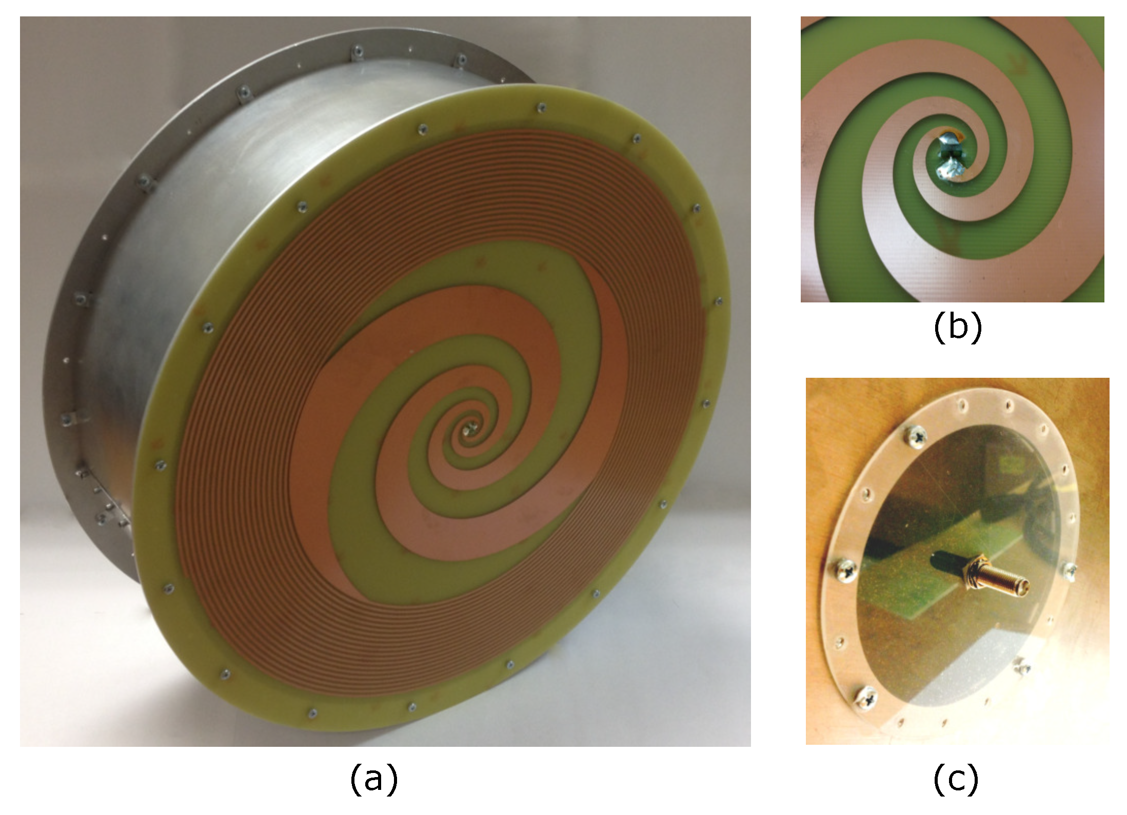
2. Antenna Structure and Design Approach

The proposed antenna consists of three main parts: compound spiral, cavity and balun (see Figure 1). The design requirements in the bandwidth from 500 MHz to 5 GHz are: (i) return loss of 10 dB or better, (ii) front-to-back ratio of 6 dB or more, and (iii) minimum AR within 45° of boresight less than 6 dB. The antenna must be low-cost and easy to fabricate. It is designed using HFSS [38]. CST [39] is used for verification. The design shown here is for right-hand polarization. We have also implemented the analogous left-hand polarized antenna, the performance of which is very similar to the results reported here in terms of impedance bandwidth, gain and axial ratio.

2.1. Compound Spiral

The compound spiral (Figure 2) is printed on a 1 mm thick FR-4 PCB with a diameter of 367 mm. The expressions defining the edges r e 1 and r e 2 of one of the equiangular-spiral arms are
r e 1 = r 0 exp ( α e θ e 1 ) ,
r e 2 = r 0 exp ( α e θ e 2 )
where r 0 = 5 mm, α e = 0.25 , 0 θ e 1 θ e , m a x , θ e , m a x = 4 π and θ e 2 = θ e 1 π / 2 . The second equiangular arm is defined by the same expressions except for the angle θ e 1 , which now sweeps the angles from π to θ e , m a x + π . Similarly, the edges of the arms of the printed Archimedean spiral are described by
r a 1 = α a ( θ a θ e , m a x ) r 0 exp ( α e θ e , m a x )
r a 2 = α a ( θ a θ e , m a x ) [ r 0 exp ( α e θ e , m a x ) w ]
where α a = 0.25 , w = 1 mm and θ e , m a x θ a 20 π . The shape parameters of the equiangular and Archimedean spiral portions were optimized simultaneously for best impedance match from 500 MHz to 5 GHz. The optimization was first applied to the spiral structure without the cavity and then re-optimized in the presence of the cavity. As shown in Section 3, an impedance match better than 10 dB reflection loss was actually achieved from 350 MHz to 5.5 GHz. The Archimedean portion of the spiral is critical in achieving this wideband impedance match while keeping the antenna diameter below 360 mm. This is because the Archimedean shape offers significant length extension of the spiral arms within the available space, ensuring gradual current decay toward the arms’ ends. This gradual decay is particularly important in the presence of the cavity, the walls of which are very close to the ends of the spiral arms. It has minimal impact on the antenna efficiency when an FR-4 substrate is used. As shown in Section 3, the loss contribution of the FR-4 material is far greater than the loss contribution of the copper traces forming the spiral (including the Archimedean portion). Likewise, the gain of the antenna is fairly insensitive to the proportion of the area occupied by the Archimedean spiral within the overall available area as long as this proportion ensures the required impedance match.

2.2. Center Raised Cylindrical Cavity

In order to suppress the backward radiation, the compound spiral is backed by a metallic cavity. As discussed in Section 1, cavities negatively impact the antenna’s broadband impedance, AR and gain patterns [18,19,27,28]. Mitigation strategies include absorbing materials inside the cavity or termination resistors [21,35,36], which reduce the antenna efficiency. Here, we propose an absorber-free center-raised cylindrical cavity (see Figure 1) which is easy to fabricate due to its simple geometry. It significantly improves the front-to-back ratio. The compound spiral was optimized together with the cavity in order to preserve the wideband impedance match. We should mention that, without the cavity, the spiral achieves even wider impedance bandwidth from 300 MHz all they way up to 6 GHz. However, with the cavity, the impedance match is compromised even within the specified bandwidth from 500 MHz to 5 GHz, which necessitates an additional optimization cycle where the spiral and the cavity shape parameters are tuned simultaneously. The underlying design principle employs a reflecting surface at a distance of about λ m i n / 4 ( λ is wavelength) from the antenna center, where the higher frequencies are radiated, whereas the reflector is at about λ m a x / 4 from the spiral elsewhere. This design principle can further be utilized to improve performance across the required bandwidth by having multiple raised sections, each corresponding to a λ / 4 distance from the spiral that relates to the radiated frequency at that section. This does however increase complexity and hence fabrication costs. An additional advantage of the center-raised cylinder is that it houses the feed balun on the outside (see Figure 1) thus shielding it from the antenna.
The dimensions for the center-raised cylindrical cavity (refer to Figure 1) are: h 1 = 126 mm (cavity height), h 2 = 105 mm (height of raised cylinder), D 1 = 364 mm (cavity diameter including the rim) and D 2 = 106 mm (diameter of the center-raised cylinder). It should be noted that neither the cavity height nor the raised cylinder height correspond to the exact theoretical λ / 4 values that relate to the minimum and maximum frequencies, but were rather optimized to obtain the best performance across the full frequency band.

2.3. Balun

A printed balun is designed to transform an unbalanced (coaxial) 50 Ω feed to the spiral’s balanced port, the simulated impedance of which varies from about 120 j 10 Ω at low frequencies to about 150 + j 20 Ω at high frequencies. It consists of five linear-taper metallic sections at the bottom and the top of a 1.6 mm thick FR-4 PCB (see Figure 3). The balun design relies on a gradual transition from the balanced to unbalanced port to obtain an acceptable wide-band impedance match where a more gradual transition translates to a higher bandwidth. This gradual transition was found to be most effectively obtained within the physical length constraints through the use of differently tapered sections. Due to the varying input to output impedance ratios from the lower to higher frequencies, the structure needs to be tuned through simulation within the whole antenna, spiral and cavity included, to obtain an optimal impedance match. Section 1 is a short 50 Ω microstrip line interfacing the coaxial port. Its bottom (ground) layer’s width is five times the strip width. The balanced port of the antenna interfaces section 7, which is a short symmetrical strip line [40]. Sections 2–6 consist of top and bottom linearly tapered traces which provide the impedance transformation. Table 1 lists the shape parameters of the balun’s sections. The design is constrained to keep the balun’s total length equal to h 1 = 126 mm so that it fits within the raised portion of the cavity.

3. Results

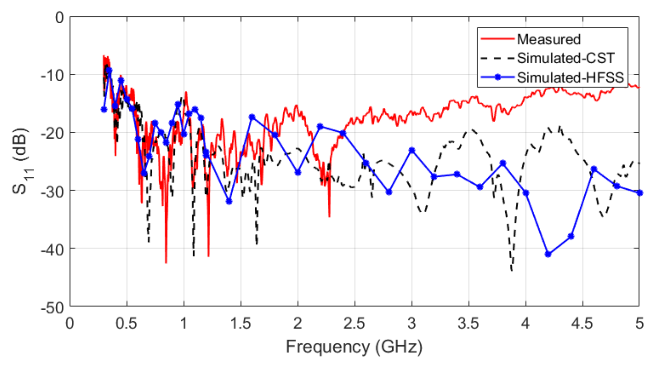
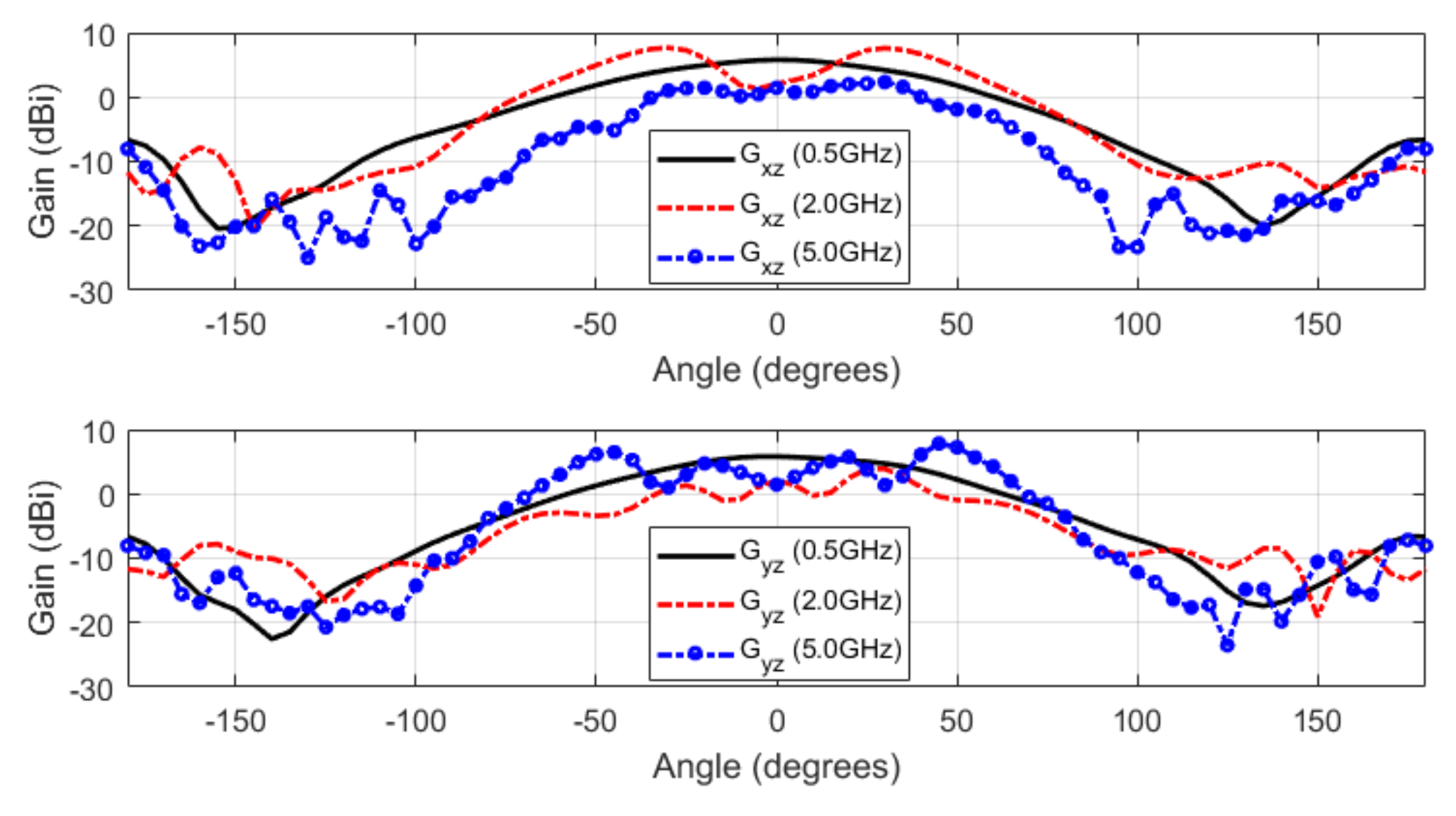
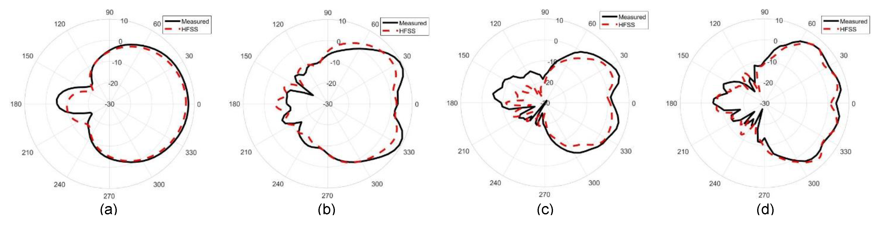
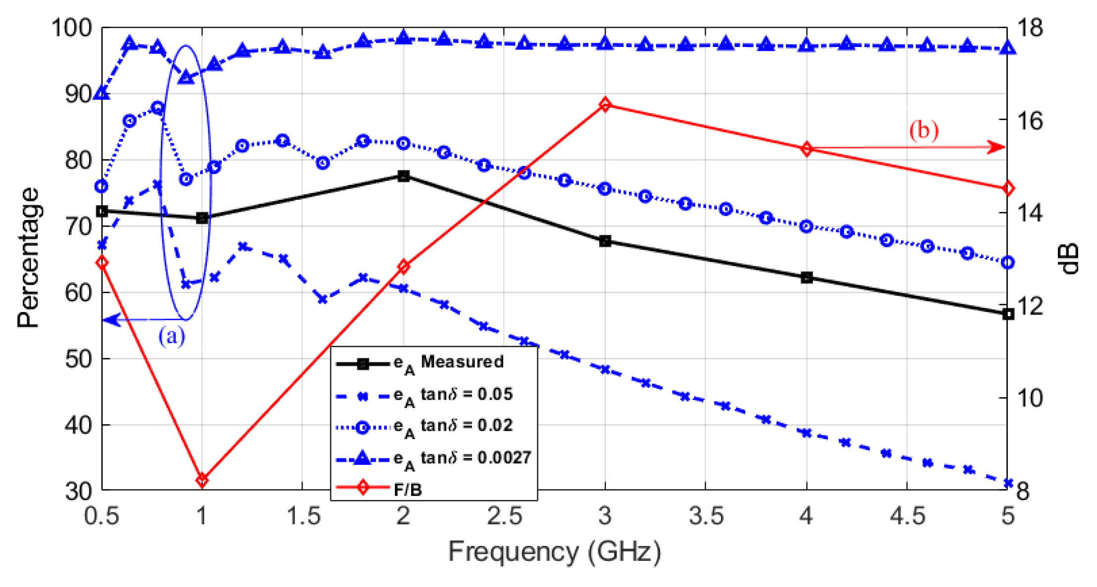
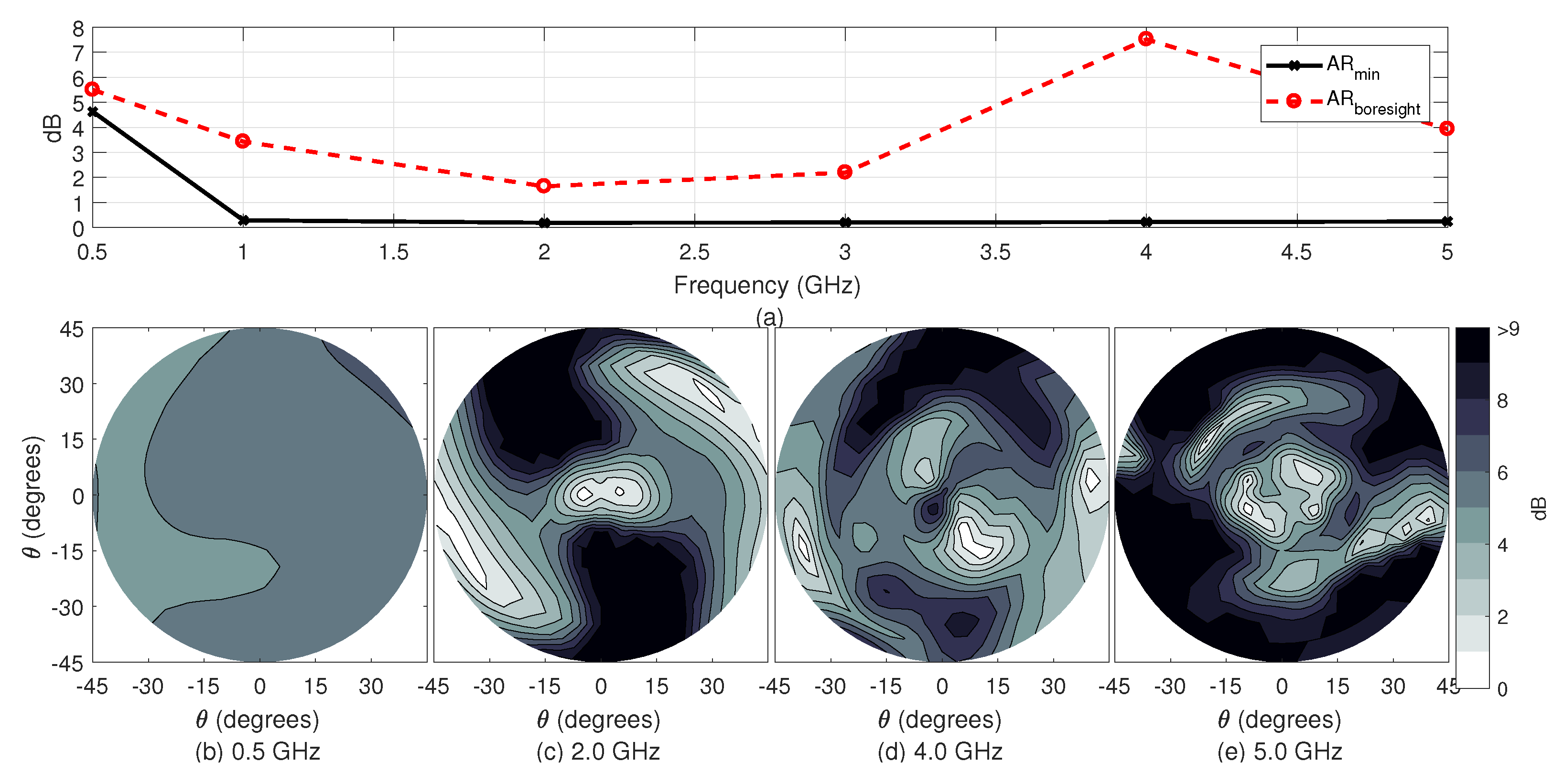
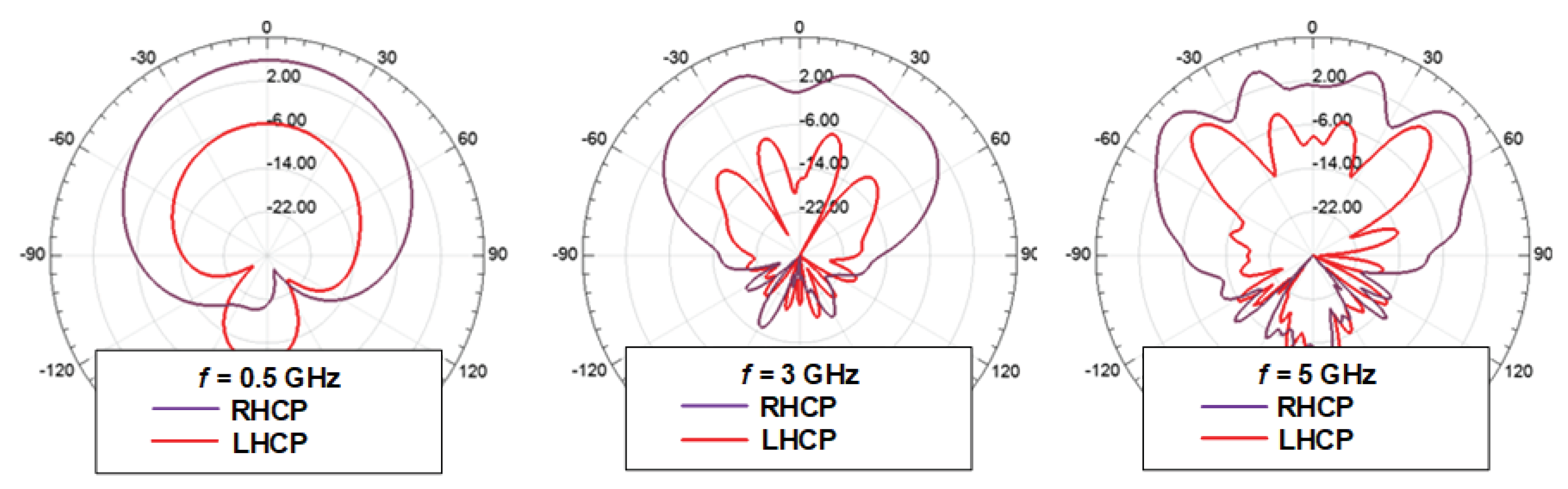
3.1. Frequency-Domain Performance

Figure 4 shows the fabricated antenna, which costs roughly 113 USD—23 USD for both the spiral antenna and balun and 90 USD for the cavity, to fabricate a unit. Figure 5 shows the measured and simulated (HFSS [38] and CST [39]) reflection coefficient versus frequency. It is better than −10 dB from 350 MHz to beyond 5 GHz. The three curves agree well at lower frequencies, but as the frequency increases, so too does the disagreement. This is attributed to the high uncertainty in the properties of the FR-4 substrate, which are not provided by the manufacturer in the GHz range. CST, which uses a transient solver, uses FR-4 parameters of ϵ r = 4.3 and t a n δ = 0.025 at 10 GHz in its library whereas HFSS, which uses a frequency domain solver, uses ϵ r = 4.4 and t a n δ = 0.02 at 9.4 GHz.
The simulated input impedance at the balun’s input ranges from 65 j 10 Ω at low frequencies to 50 + j 0 Ω at high frequencies as compared to the respective values of 120 j 10 Ω and 150 + j 20 Ω at the spiral’s input.
Far-field measurements were done in a commercial antenna-measurement facility. The measured total gain patterns are reported here in two elevation planes, xz and yz (z is along boresight). The elevation angle θ spans the range [ π , π ] . Figure 6 shows the gain patterns at 0.5, 2 and 5 GHz. Pattern ripples close to boresight are observed above 1 GHz. Simulations confirm the effect to be due to the cavity, i.e., no ripples are observed if the cavity is removed. Pattern distortions due to loss-free reflectors are well-known [27] and the ripple effect is expected. Finally, Figure 7 shows a comparison of simulated and measured gain patterns at sample frequencies. Good agreement is observed especially within the cone defined by an elevation angle of 45 degrees.
This antenna is developed for a concealed-weapon detection close-range radar, where gain is important not only at boresight but within ± 45 ° from it, translating into illuminating a person of about 1.8 m height at about 1 m stand-off distance. Within this beamwidth, the maximum total gain varies from about 5 dBi to about 8 dBi in the whole frequency band (see Table 2). The boresight total gain values are also shown in Table 2. The maximum gain values are significantly higher than those reported in the literature for cavity-backed spirals with impedance bandwidths close to 10:1, e.g., 3.4 to 6.1 dBi in [28] (simulated), 10 to 6 dBi in [26], 2.5 to 5 dBi in [24] and 1.77 to 2.37 dBi in [23]. We note, however, that these designs employ absorbing or EBG cavities, mitigating the ripples in the gain patterns and implying that the maximum reported gain is that at boresight. The boresight gain in Table 2 is similar or only slightly better in comparison.
Figure 8 shows the front-to-back ratio (F/B) versus frequency. It is better than 8 dB from 0.5 GHz to beyond 5 GHz. The F/B is calculated from the measured 3-D field patterns as the ratio of the total power in the forward half-space ( 0 ° θ 90 ° ) and that radiated backwards ( 90 ° < θ 180 ° ) .
Figure 8 also shows the measured antenna efficiency e A , which is about 75% up to 2 GHz after which it decreases steadily to 57% at 5 GHz. The efficiency is also obtained from simulations to compare the loss contribution of the FR-4 substrate to the conductor loss (copper with σ = 5.7 · 10 7 S/m). The substrate permittivity is set to 4.5 whereas tan δ is set to 0.05, 0.02 and 0.0027 in three separate simulations. Here, tan δ = 0.0027 corresponds to a low-loss substrate, e.g., Rogers 4003C. It is evident that the losses are due mostly to the FR-4 substrate, with tan δ = 0.02 providing the closest match with measurements. It is also evident that utilizing this absorber-free cavity yields improved efficiency of 57% to 75% using a high loss FR-4 substrate as compared to 40% to 45% when using an absorptive backing and low loss substrates [1]. Simulation results further show that if a comparable low loss substrate is used in the proposed cavity, efficiency above 90% is achievable.
Figure 9 summarizes the results for the measured AR. Figure 9a shows the boresight and the minimum AR within 45 ° of boresight versus frequency. The minimum AR is the highest (4.6 dB) at 0.5 GHz and it is well below 1 dB at and beyond 1 GHz. Such AR values are comparable to the boresight AR of the spiral antennas employing absorbing or EBG cavities. However, similarly to the gain, the AR distribution varies within 45 ° of boresight. In particular, the boresight AR is below 6 dB at all measured frequencies except at 4 GHz where it is 7.5 dB. To appreciate the range of variation, Figure 9b–d show the AR contour plots within 45 ° from boresight at 0.5 GHz, 4 GHz, and 5 GHz. The 4 GHz plot is chosen in addition to the lowest and highest frequencies because it corresponds to the worst boresight AR. It is clear that the minimum AR value of 0.2 dB is close to boresight (within 6 ° ) but the AR variation is anywhere between 0 dB and 9 dB. As mentioned in the Introduction, absorber-free metallic cavities are known to distort the AR and gain patterns of spiral antennas [27]. The distortions appear in the form of ripples close to boresight, which ripples may shift the minimum AR (and maximum gain) off boresight.
It is worth noting that the gain and AR distributions in the cone of 45 ° off boresight show strong correlation between the directions of minimum gain and maximum AR.
To illustrate further the polarization performance of the antenna, Figure 10 shows plots of the right-hand circular polarization (RHCP) and left-hand circular polarization (LHCP) gain patterns at sample frequencies in the x z plane.

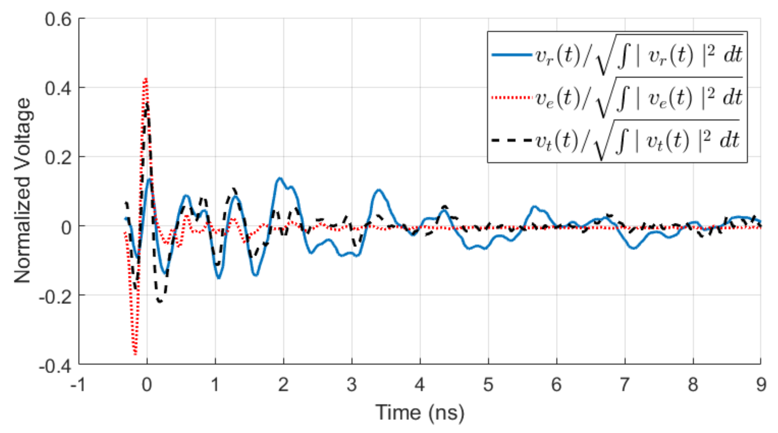
3.2. Time–Domain Performance

The fidelity factor F quantifies the dispersion characteristics of an antenna, i.e., the distortion it causes on a broadband signal upon transmission or reception [41]. It is calculated as the maximum cross-correlation between the transmitted v t ( t ) and received v r ( t ) time–domain signals [42]:
F = m a x + v t ( t ) · v r ( t τ ) d t + v t ( t ) 2 d t · + v r ( t ) 2 d t .
To obtain F through measurements, the approach in [42] was used. It employs two identical antennas aligned along boresight. One antenna transmits with the excitation signal v e ( t ) at its input. The signal received at the terminals of the second antenna is v r ( t ) . The excitation v e ( t ) is measured directly at the output of the signal generator. The transmitted signal v t ( t ) is extracted in the frequency domain using [42]:
V t ( ω ) = j 2 k 0 d · V e ( ω ) · V r ( ω ) e j k 0 d
where V t ( ω ) , V r ( ω ) and V e ( ω ) are the Fourier transforms of v t ( t ) , v r ( t ) and v e ( t ) , respectively, k 0 is the free-space wavenumber and d is the distance between the antennas.
In our measurement setup, two identical spiral antennas were positioned facing each other in an anechoic chamber with a separation d = 4.2 m (limited by the chamber size) as shown in Figure 11. A generator similar to the one in [43] provides excitation with a differentiated Gaussian pulse with a 10 dB bandwidth from 450 MHz to 4.8 GHz. The received signal v r ( t ) and the excitation signal v e ( t ) were measured with a Keysight InfiniiVision 6000 X-Series oscilloscope. Figure 12 shows v r ( t ) and v e ( t ) along with the calculated v t ( t ) after normalization and alignment for maximum correlation. Using (5) and (6), the fidelity was calculated to be F 0.62 , which is comparable with that of other spiral antennas [42]. For reference, we note that the same setup was used to measure the fidelity of an UWB linearly polarized antipodal antenna with a similar bandwidth, with the result being F 0.85 . It is worth noting that no secondary pulse is observed in the received voltage v r ( t ) (see Figure 12) as the one reported in [16].

4. Conclusions

A low-cost high-efficiency cavity-backed spiral antenna is proposed, which achieves: (i) 16:1 impedance bandwidth (from 350 MHz to 5.5 GHz, at 10 dB reflection loss), (ii) front-to-back ratio better than 8 dB, (iii) maximum gain within the cone of 45 ° off boresight ranging from 5 to 8 dBi, and (iii) efficiency ranging from 72% at 500 MHz to 57% at 5 GHz despite the high loss of the FR-4 substrate. Simulations indicate that the efficiency is well above 90% if low-loss substrates are used (with ten-fold price increase). The maximum gain values are significantly higher than those reported in the literature for cavity-backed spirals with similar impedance bandwidths, e.g., 3.4 dBi to 6.1 dBi in [28] (simulated), 10 dBi to 6 dBi in [26], 2.5 dBi to 5 dBi in [24] and 1.77 dBi to 2.37 dBi in [23]. Efficiency is also significantly higher than that typically reported for spiral antennas with absorptive backing, e.g., 40% to 45% [20,37]. These performance metrics are superior to reported cavity-backed spirals and they prove that absorber-free center-raised cavities can ensure unidirectional patterns while maintaining extremely wide impedance bandwidths. In terms of AR and fidelity, the proposed design is comparable to existing absorber-free reflector-backed spirals. The drawback of absorber-free cavities is in the AR and gain pattern distortions (ripples close to boresight), which may shift the directions of maximum gain and minimum AR off boresight. Such distortions are acceptable in the close-range application for which the antenna is designed (concealed-weapon detection radar system [44,45]). However, if patterns with a single maximum along boresight are required, the use of absorbers or terminating resistors is necessary. Such mitigation strategies are certainly applicable to the current design. It is also worth noting that the size of the antenna is comparable to that of reported UWB spirals. Its diameter as a fraction of the largest wavelength is 0.425, which is comparable to: 0.404 in [23], 0.336 in [24], 0.434 in [26] and 0.432 in [28].

Author Contributions

Conceptualization, Y.L.; methodology, Y.L.; validation, C.B.; formal analysis, C.B.; investigation, C.B.; resources, Y.L.; writing—original draft preparation, C.B.; writing—review and editing, C.B.; supervision, N.N.; project administration, N.N.; funding acquisition, N.N. All authors have read and agreed to the published version of the manuscript.

Funding

This research was funded by Natural Sciences and Engineering Research Council of Canada (NSERC), grant CRDPJ 522367-17, the Ontario Centres of Excellence (OCE) grant OCE VIP II #30493, and Patriot One Tech. Inc.

Conflicts of Interest

The authors declare no conflict of interest.

References

  1. Sachs, J. Handbook of Ultra-Wideband Short-Range Sensing: Theory, Sensors, Applications; Wiley-VCH Verlag & Co. KGaA: Weinheim, Germany, 2012. [Google Scholar]
  2. Nguyen, C.; Han, J. Time-Domain Ultra-Wideband Radar, Sensor and Components; Springer: Berlin/Heidelberg, Germany, 2014. [Google Scholar]
  3. Taylor, J.D. Ultrawideband Radar: Applications and Design; CRC Press: Boca Raton, FL, USA, 2016. [Google Scholar]
  4. Dyson, J.D. A survey of the very wide band and frequency independent antennas—1945 to the present. J. Res. Nat. Bur. Stand.–(Radio Propag.) 1962, 66, 1–6. Available online: https://nvlpubs.nist.gov/nistpubs/jres/66d/jresv66dn1p1_a1b.pdf (accessed on 27 August 2020). [CrossRef] [Green Version]
  5. Curtis, W. Spiral antennas. IRE Trans. Antennas Propag. 1960, 8, 289–306. [Google Scholar] [CrossRef]
  6. Rumsey, V.H. Frequency Independent Antennas; Academic Press: Cambridge, MA, USA, 1966. [Google Scholar]
  7. Corzine, R.G.; Mosko, J.A. Four-Arm Spiral Antennas; Artech House: Norwood, MA, USA, 1990. [Google Scholar]
  8. DuHamel, R.H.; Chadwick, G.G. Frequency-independent antennas. In Antenna Engineering Handbook, 2nd ed.; Johnson, R.C., Jasik, H., Eds.; McGraw-Hill Book Company: New York, NY, USA, 1984; Chapter 14; pp. 14-16–14-26. [Google Scholar]
  9. Filipović, D.S.; Cencich, T. Frequency-independent antennas. In Antenna Engineering Handbook, 4th ed.; Volakis, J.L., Ed.; Mc-Graw-Hill: New York, NY, USA, 2007; Chapter 13. [Google Scholar]
  10. Nakano, H. Frequency-independent antennas: Spirals and log-periodics. In Modern Antenna Handbook; Balanis, C.A., Ed.; Wiley Online Library: Hoboken, NJ, USA, 2007; Chapter 6. [Google Scholar]
  11. Stutzman, W.L.; Thiele, G.A. Antenna Theory and Design, 3rd ed.; Wiley: Hoboken, NJ, USA, 2013. [Google Scholar]
  12. Balanis, C.A. Antenna Theory: Analysis and Design, 4th ed.; Wiley: Hoboken, NJ, USA, 2013. [Google Scholar]
  13. Sheen, D.; McMakin, D.; Hall, T. Near-field three-dimensional radar imaging techniques and applications. Appl. Opt. 2010, 49, E83–E93. [Google Scholar] [CrossRef] [PubMed]
  14. Volakis, J.L.; Nurnberger, M.W.; Filipović, D.S. Broadband cavity-backed slot spiral antenna. IEEE Antennas Propag. Mag. 2001, 43, 15–26. [Google Scholar] [CrossRef]
  15. McFadden, M.; Scot, W. Analysis of the equiangular spiral antenna on a dielectric substrate. IEEE Trans. Antennas Propag. 2007, 55, 3163–3171. [Google Scholar] [CrossRef]
  16. McFadden, M. Analysis of the Equiangular Spiral Antenna. Ph.D. Thesis, School of Electrical and Computer Engineering, Georgia Institute of Technology, Atlanta, GA, USA, 2009. [Google Scholar]
  17. Fumeaux, C.; Baumann, D.; Vahldieck, R. Finite-volume time-domain analysis of a cavity-backed Archimedean spiral antenna. IEEE Trans. Antennas Propag. 2006, 54, 844–851. [Google Scholar] [CrossRef]
  18. Nakano, H.; Nogami, K.; Arai, S.; Mimaki, H.; Yamauchi, J. A spiral antenna backed by a conducting plane reflector. IEEE Trans. Antennas Propag. 1986, 34, 791–796. [Google Scholar] [CrossRef]
  19. Nakano, H.; Soga, H.; Honma, T.; Yamauchi, J. Effects of adding a small disk to a spiral antenna backed by a conducting plane reflector. IEE Proc. H Microwaves Antennas Propag. 1991, 138, 375–377. [Google Scholar] [CrossRef]
  20. Nakano, H.; Kikkawa, K.; Iitsuka, Y.; Yamauchi, J. Equiangular spiral antenna backed by a shallow cavity with absorbing strips. IEEE Trans. Antennas Propag. 2008, 56, 2742–2747. [Google Scholar] [CrossRef] [Green Version]
  21. Serhir, M.; Guinvarc’h, R. A low-profile cavity-backed dual-polarized spiral antenna array. IEEE Antennas Wirel. Propag. Lett. 2013, 12, 524–527. [Google Scholar] [CrossRef]
  22. Sammeta, R.; Filipović, D.S. Quasi frequency-independent increased bandwidth planar log-periodic antenna. IEEE Trans. Antennas Propag. 2014, 62, 1937–1944. [Google Scholar] [CrossRef]
  23. Sheikh, Z.; Tahir, F.A. Gain enhancement of low profile cavity backed spiral antenna at low frequencies. In Proceedings of the Progress of the 2017 Progress in Electromagnetics Research Symposium-Fall (PIERS-FALL), Singapore, 19–22 November 2017; pp. 1771–1773. [Google Scholar]
  24. Hamza, M.; Khan, W.T. Hybrid utilization of loading techniques and cavity groove for performance enhancement of the UWB (2–18 GHz) spiral antenna. Int. J. Antennas Propag. 2018, 2018, 9167154. [Google Scholar] [CrossRef]
  25. Acree, M.A.; Prata, A. Archimedean spiral-mode microstrip antenna with improved axial ratio. In Proceedings of the IEEE AP-S/URSI International Symposium on Antennas and Propagation, Orlando, FL, USA, 11–16 July 1999; Volume 2, pp. 1232–1235. [Google Scholar]
  26. Liu, C.; Lu, Y.; Du, C.; Cui, J.; Shen, X. The broadband spiral antenna design based on hybrid backed-cavity. IEEE Trans. Antennas Propag. 2010, 58, 1876–1882. [Google Scholar]
  27. Buck, M.C.; Filipović, D.S. Spiral cavity backing effects on pattern symmetry and modal contamination. IEEE Antennas Wirel. Propag. Lett. 2006, 5, 243–246. [Google Scholar] [CrossRef]
  28. Ding, F.; Zhang, F.; Zhang, Y. The broadband composite structure spiral antenna with a ladder-shaped backed-cavity. In Proceedings of the 2011 4th IEEE International Symposium Microwave, Antenna, Propagation and EMC Technologies for Wireless Communications, Beijing, China, 1–3 November 2011; pp. 120–123. [Google Scholar]
  29. Shire, A.M.; Jahun, K.I.; Ashwal, W.A.; Jenu, M.Z.M.; Ramli, K.N. Effects of cavity ground plane on UWB Archimedean spiral antenna. In Proceedings of the 2015 IEEE International Conference on Computer, Communication, and Control Technology (I4CT 2015), Sarawak, Malaysia, 21–23 April 2015. [Google Scholar]
  30. Kim, H.-B.; Hwang, K.-C.; Kim, H.-S. Cavity-backed two-arm spiral antenna with a ring-shaped absorber for partial discharge diagnosis. J. Electr. Eng. Technol. 2013, 8, 856–862. [Google Scholar] [CrossRef]
  31. Louertani, K.; Chio, T.-H. Hybrid equi-angular to Archimedean spiral antenna. In Proceedings of the 2012 IEEE International Symposium on Antennas and Propagation, Chicago, IL, USA, 8–14 July 2012. [Google Scholar]
  32. Wang, Y.; Wang, G.; Yu, Z. Design of a highly miniaturized compound spiral antenna. In Proceedings of the International Symposium on Signals, Systems and Electronics, Nanjing, China, 16–19 September 2010. [Google Scholar]
  33. Zhao, Y.; Hu, W. Design of a UWB unidirectional radiation compound spiral antenna. In Proceedings of the IEEE 6th International Symposium on Microwave, Antenna, Propagation, and EMC Technologies (MAPE), Shanghai, China, 28–30 October 2015. [Google Scholar]
  34. Chen, M.; Wang, G.; Zhou, S. Novel compound planar spiral antenna. In Unifying Electrical Engineering and Electronics Engineering: Proceedings of the 2012 International Conference on Electrical and Electronics Engineering; Springer: Berlin/Heidelberg, Germany, 2013; pp. 1493–1500. [Google Scholar]
  35. Maldonado-Vargas, J.; Rodríguez-Solís, R.A.; Elmansouri, M.A.; Filipovic, D.S. A UWB cavity-backed compound power-Archimedean slot spiral for body centric wireless communications applications. In Proceedings of the IEEE AP-S/URSI International Symposium on Antennas and Propagation, Vancouver, BC, USA, 19–25 July 2015; pp. 1978–1979. [Google Scholar]
  36. Zhu, Y.-X.; Zhong, S.-S.; Xu, S.-Q. Miniaturized compound spiral slot antenna. Microw. Opt. Tech. Lett. 2008, 50, 2799–2801. [Google Scholar]
  37. Elmansouri, M.A.; Filipovic, D.S. Low-dispersion spiral antennas. IEEE Trans. Antennas Propag. 2012, 60, 5522–5530. [Google Scholar] [CrossRef]
  38. ANSYS HFSS (19.2.0), ANSYS. Available online: https://www.ansys.com/products/electronics/ansys-hfss (accessed on 17 September 2019).
  39. CST Studio Suite. Dassault Systèmes. 6–15 June 2018. Available online: https://www.3ds.com/products-services/simulia/products/cst-studio-suite/ (accessed on 17 September 2019).
  40. Wheeler, H.A. Transmission-line properties of parallel strips separated by a dielectric sheet. IEEE Trans. Microw. Theory Tech. 1965, 13, 172–185. [Google Scholar] [CrossRef]
  41. Quintero, G.; Zurcher, J.; Skrivervik, A. System fidelity factor: A new method for comparing UWB antennas. IEEE Trans. Antennas Propag. 2011, 59, 2502–2512. [Google Scholar]
  42. Elmansouri, M.; Radway, M.; Filipović, D. Frequency- and time-domain performance of four-arm mode-2 spiral antennas. IEEE Trans. Antennas Propag. 2012, 60, 2627–2634. [Google Scholar] [CrossRef]
  43. Pitcher, A.D.; McCombe, J.J.; Eveleigh, E.A.; Nikolova, N.K. Compact transmitter for pulsed-radar detection of on-body concealed weapons. In Proceedings of the IEEE MTT-S International Microwave Symposium, Philadelphia, PA, USA, 10–15 June 2018. [Google Scholar]
  44. Nikolova, N.K.; Thayaparan, T. Ultra-Wideband (UWB) High-Resolution Noise Radar for Concealed Weapon Detection. Tech. Report DRDC-Ottawa TR 2013-160, Defence Research and Development Canada. February 2014. Available online: https://cradpdf.drdc-rddc.gc.ca/PDFS/unc231/p804019_A1b.pdf (accessed on 27 August 2020).
  45. Nikolova, N.K.; McCombe, J.J. On-Body Concealed Weapon Detection System. U.S. Patent No. 10,229,328, 12 March 2019. Available online: https://patentimages.storage.googleapis.com/0f/d5/1e/a1a32e2f905ec5/US20150379356A1.pdf (accessed on 27 August 2020).
Figure 1. Overall view of the cavity-backed compound-spiral antenna structure.
Electronics 09 01399 g001
Figure 2. Planar view of the compound-spiral antenna structure. Enlarged views show in greater detail the balanced antenna port (top inset) and the fine structure of the outer Archimedean spiral (bottom inset).
Electronics 09 01399 g002
Figure 3. Planar view of the printed balun, consisting of seven sections (numbered at the bottom); for geometrical details see Table 1.
Electronics 09 01399 g003
Figure 4. Assembled cavity-backed compound-spiral antenna: (a) front view; (b) spiral’s feed; (c) raised portion of the cavity with the mounted balun.
Electronics 09 01399 g004
Figure 5. Measured and simulated reflection coefficient of the proposed antenna.
Electronics 09 01399 g005
Figure 6. Measured total gain at 0.5, 2 and 5 GHz, plotted in two principal elevation planes, x z and y z , where z is along the antenna’s boresight.
Electronics 09 01399 g006
Figure 7. Sample plots comparing simulated and measured total gain patterns at: (a) 0.5, (b) 2, (c) 4 and (d) 5 GHz. Patterns are plotted in the y z plane.
Electronics 09 01399 g007
Figure 8. (a) Measured and simulated antenna efficiency e A versus frequency (in percentage) where the loss tangent of the substrate in simulations is set to: 0.05, 0.02 and 0.0027. (b) Measured front-to-back ratio (F/B) in dB versus frequency.
Electronics 09 01399 g008
Figure 9. (a) Measured axial ratio (AR) at boresight and minimum (within 45 ° of boresight) AR versus frequency. Contour plots of the measured AR at: (b) 0.5, (c) 2.0, (d) 4.0 and (e) 5.0 GHz.
Electronics 09 01399 g009
Figure 10. Sample plots comparing the right-hand circular polarization (RHCP) and left-hand circular polarization (LHCP) gain patterns in the x z plane at: 0.5, 3 and 5 GHz.
Electronics 09 01399 g010
Figure 11. Antenna fidelity measurement setup.
Electronics 09 01399 g011
Figure 12. Normalized excitation, received and transmit signals after temporal alignment for maximum correlation.
Electronics 09 01399 g012
Table 1. Balun’s shape parameters.
SectionLength (mm)Gradient TopGradient Bottom
11.0000.00000.0000
210.00 0.0350 0.3500
319.50 0.0103 0.0641
429.25 0.0077 0.0222
529.25 0.0077 0.0256
631.00 0.1500 0.0323
71.0000.00000.0000
Table 2. Maximum and boresight measured total gain.
Frequency (GHz)0.51.02.03.04.05.0
Maximum (dBi)5.84.718.558.276.717.86
Boresight (dBi)5.8 2.75 2.07 0.14 0.00931.14

