Communication

High-Speed and High-Power Ge-on-Si Photodetector with Bilateral Mode-Evolution-Based Coupler

1
Institute of Microelectronics, Chinese Academy of Sciences, Beijing 100029, China
2
University of Chinese Academy of Sciences, Beijing 100049, China
*
Authors to whom correspondence should be addressed.
Photonics 2023, 10(2), 142; https://doi.org/10.3390/photonics10020142
Submission received: 2 December 2022 / Revised: 19 January 2023 / Accepted: 22 January 2023 / Published: 30 January 2023
(This article belongs to the Special Issue Emerging Frontiers in Silicon Photonics)

Abstract

:
We propose a germanium-on-silicon photodetector with a bilateral mode-evolution-based coupler. Based on the double-sided mode-evolution, the light illuminates the whole Ge absorption region uniformly, which alleviates the space-charge effects and decreases the saturation effects. The simulated results show 53% more photocurrent generation and more than 19 times the opto-electrical bandwidth than conventional butt-coupled photodetectors under high-power illumination. In addition, an equivalent circuit model is presented to investigate the limiting factors of bandwidth. A genetic algorithm is used to extract the parameter values of components in an equivalent circuit by fitting the simulated two-port S 22 parameter. The results show significant improvement in high-power and high-speed performance compared with conventional butt-coupled detectors.

1. Introduction

In microwave photonics and analog optical links [1,2,3], the photodetectors with large bandwidth, high-power handling capability and high linearity are greatly needed. Different from their counterparts operating at weak input light power (usually less than 1 mW) [4,5,6,7], the photodetectors operating at high input power (usually 10 mW or higher) [8,9,10] suffer from three distinctive drawbacks. The thermal effects [11] are the first obstacle for the photodetectors to achieve linearity at high-power operation. The heat restricted in the absorption region will lead to temperature build-up and, ultimately, thermal failure. These effects are particularly significant in waveguide integrated detectors due to the compact size. The second drawback is the mode mismatch between the bus waveguide and absorption structure. Power loss arises from the reflection of the incident light power at the interface of the bus waveguide and the absorption region. Thirdly, the incident light will be strongly absorbed in the first few micrometers of the detector, resulting in local charge accumulation. This is called space-charge effects [11] or field-screening effects [12] because the built-in electric field is weaken by the accumulated space charge. Over the past decades, various photodetectors in the InP platform with new structures have been demonstrated, such as the uni-traveling carrier photodetector (UTC-PD) [13] and traveling-wave photodetector (TWPD) [12]. However, the high cost, poor thermal conductivity and difficulties of large integration confine their further application.
The development of silicon photonics [14,15,16] provides a low cost, high thermal conductivity and complementary metal oxide semiconductor (CMOS) compatible alternate to the InP platform. Silicon has a low absorption coefficient in infrared, but the successful growth of high-performance germanium on silicon wafers [17,18,19] compensates the shortage of silicon. As a result, much research on Ge-on-Si photodetectors [4,20,21,22] were demonstrated. The structures used in the InP platform was also migrated to a silicon platform to obtain high-power handling capability, such as UTC photodetectors [23] and traveling-wave photodetectors [24]. However, the UTC photodetectors suffer from a lower bandwidth, and the traveling-wave structure will increase the dark current and lower the sensitivity. Another solution to obtain high linearity is to manipulate light distribution in the absorption region. Based on this idea, a double-sided illumination structure [8,9,25] has been proposed and demonstrated, but the mode mismatch between the Si waveguide and Ge-on-Si structure remains a problem. A mode-evolution-based coupler can eliminate mode mismatch and alleviate the space-charge effects at the same time [26]. Furthermore, it is inherently broadband and shows high fabrication tolerance, which makes it more suitable for integrated photonic systems [27].
In this work, a novel structure of a mode-evolution-based coupled photodetector with two parallel Ge absorption regions is proposed. The input light is split into two beams through a multimode interferometer (MMI) and occurs in the two parallel Ge absorption regions, respectively. The benefit of the mode-evolution-based coupling other than the conventional butt coupling is that the light is absorbed uniformly in the whole Ge absorption region, which alleviates the space-charge effects. As the two parallel Ge absorption regions share the same signal and ground electrodes, the bandwidth of the proposed structure is not degraded compared with the conventional structure with a single Ge absorption region. Although the proposed structure has a larger Ge area and, therefore, a larger junction capacitance, it can be compensated by the resistance halved after the parallel connection. The improvement in the responsivity, bandwidth, and linearity of the novel photodetectors with the bilateral mode-evolution-based coupler are investigated. An equivalent circuit model is presented to study the factors that affect the bandwidth and characterize the output impendence of the detector. The component values in the equivalent circuit are extracted by fitting the microwave reflection parameter S 22 with a genetic algorithm optimizer. Based on the extracted equivalent circuit, the frequency response is calculated, which is in good agreement with the simulation results.

2. Device Structure and Working Principle

Figure 1a,b shows the comparison between the conventional butt-coupled photodetector and the proposed bilateral mode-evolution-based structure. For better comparison, the size of Ge absorption region in butt-coupled detector is set to 3   μ m × 10   μ m with a thickness of 0.5   μ m , while the two parallel Ge absorption regions in mode-evolution-based detector are both set to 1.5   μ m × 10   μ m with the same thickness of 0.5   μ m , thus the total volume of the two structures is equal. In the proposed structure, light is coupled from an optical fiber via a grating coupler to a silicon waveguide and split into two beams by MMI; optical power of each beam is reduced by half. Then, light is transferred into the Ge-on-Si region gradually and efficiently through mode-evolution-based coupler. The coupler consists of two sections. Firstly, there is a bend waveguide that gradually reduces the mode mismatch between the silicon waveguide and the Ge-on-Si structure, avoiding exciting the unwanted back-propagating modes. Then, there is a linear asymmetric taper of waveguide, whose width is linearly decreased to relax the restriction of waveguide on light and transfer the light into the Ge-on-Si structure. Finally, the two beams of light are absorbed in two parallel Ge absorption regions, respectively. Figure 1b, together with the top-view in Figure 1d, illuminate the aforementioned mode-evolution-based coupling process.
Compared with the conventional structure, the proposed evolution-based coupling is adopted to replace butt coupling, which avoids strong absorption in the first few micrometers of Ge absorption region and makes light field uniformly distributed throughout the whole Ge absorption region. Then, single Ge absorption region in conventional structure is extended into two symmetrical Ge absorption regions, which decreases the light power in each Ge absorption region to half of the original. These two improvements together alleviate the local photogenerated carrier accumulation, thus reducing the space-charge effect. The comparison of optical generation rate between the conventional coupling and bilateral mode-evolution-based coupling is illuminated in Figure 1e,f. The optical generation rate is defined as the number of photons absorbed per unit volume per unit time. Here, we have assumed that each photon is absorbed by exciting an electron-hole pair, so the optical generation rate can be considered as electron-hole pairs density per unit time in absorption regions, which reflects the local photogenerated carrier accumulation. It should be noted that the extension of Ge absorption region increases the area of Ge layer, thus increasing the capacitance, but it will not lead to bandwidth loss. As in bilateral absorption structure, junction resistance and series resistance of each Ge absorption region are connected in parallel, this halves the resistance and compensates for the increase in capacitance. This will be analyzed, in detail, in section about equivalent circuit later.
The device is designed on silicon-on insulator (SOI) substrate with 220 nm thick top silicon and 2 μ m thick buried oxide (BOX). Germanium layer epitaxial growth on the top silicon layer. The thickness and width of Ge epitaxial layer are set to 0.5 and 1.5 μ m , respectively. The PIN diode is formed by the N++-doped germanium, intrinsic germanium and P+-doped silicon slab, while the N++-doped germanium and the P++-doped silicon forms the ohmic contact with the metal. The N++ Ge and P++ Si is Gaussian-doped with a peak concentration of 1.27 × 10 21   cm 3 and 3.5 × 10 19   cm 3 , respectively. P+ Si slab is uniformly doped with a doping concentration of 1 × 10 19   cm 3 . The heavy doped Si slab decreases the serial resistance and improves the RC bandwidth. The cross-section in Figure 1c illuminates the position relationship of the structures formed by the aforementioned process flow. The whole process flow can be accomplished on the silicon photonic platform.
The geometric parameters of mode-evolution-based coupler are illustrated in Figure 1d, among which the taper length and bend radius are the most critical. Based on the couped local mode theory [27,28], the evolution of the mode amplitude b m ( z ) can be described by the coupled local mode equations:
d b m ( y ) d y + j β m ( y ) b m ( y ) = n κ m n ( y ) b n ( y ) ,
where β m ( z ) is the local propagation constant of mode m and κ m n ( z ) is the local coupling coefficient between mode m and mode n , given by
κ m n ( y ) = ω 4 1 β m ( y ) β n ( y ) e m * · e n d d y ε ( y ) d A   ,
where d A represents the integral on the cross-section perpendicular to the direction of propagation, e m * represents the power normalized local vector electric field of mode m , and * denotes complex conjugate. Solving the coupled local mode equations can determine the expression of power P m accumulated in mode m :
P m ( y ) = | b m ( y ) | 2 = 2 | b k ( 0 ) | 2 | κ ¯ δ β ¯ | [ 1 cos ( δ β ¯ y ) ] ,
where δ β ¯ is the average difference of the propagation constant β m ( y ) and β n ( y ) , κ ¯ is the average value of the coupling coefficient, and y is the direction of propagation (see Figure 1b). From Equation (3), it can be seen that the power transferred from mode n to mode m is proportional to κ ¯ . From Equation (2), it can be seen that κ m n ( y ) is reduced by decreasing d / d y ε ( y ) . This means the transition along the direction of propagation must be gradual, and both the taper length and the bend radius should be as long as possible. Furthermore, longer taper length corresponds to longer Ge absorption regions. The power absorbed in Ge absorption regions is given by:
P a b s , G e = ω I m [ ε G e ( ω ) ] 2 Ω G e d r | E ( r ) | 2 ,
where ε G e ( ω ) is the dielectric constant of Ge and Ω G e is the whole region of Ge absorption regions. Longer Ge absorption regions mean larger integral volume Ω G e ; more power is absorbed instead of leaking out at the end of Ge region. This will improve the responsivity of photodetector. However, the large length of Ge absorption regions will decrease the RC bandwidth of photodetector, which limits the high-speed application. The influence factor of bandwidth will be discussed, in detail, in Section 3. Considering the trade-off between coupling length and bandwidth, a detector length of 12 μ m was chosen. A bend radius of 5 μ m was chosen and spanned the first 1 μ m of the detector. A length of linear taper of 9 μ m was chosen, and the taper was placed 100 nm away from the Ge absorption regions. As the radius of bend is sufficiently large, the loss of light propagation in the waveguides is mainly contributed by the insert loss of MMI, which is included in the process design kit (PDK) of silicon photonic platform in Institute of Microelectronics, Chinese Academy of Sciences (IMECAS). The experimental measurement value of insert loss is 0.35 dB.

3. Modeling Results and Discussion

In this section, the simulated DC and RF characteristics of the proposed structure are presented. A conventional structure with the same size was also simulated as a reference for performance improvement. The simulation was realized using the commercial software Lumerical FDTD and Lumerical CHARGE. Firstly, the propagation of the light field from the optical source to the photodetector was simulated in the Lumerical FDTD modules using the three-dimensional (3D) finite-difference time-domain (FDTD) method to obtain the spatial distribution of the optical generation rates. Then, the optical generation rates were imported into Lumerical CHARGE to perform the optoelectronic simulation.

3.1. DC and AC Characteristics

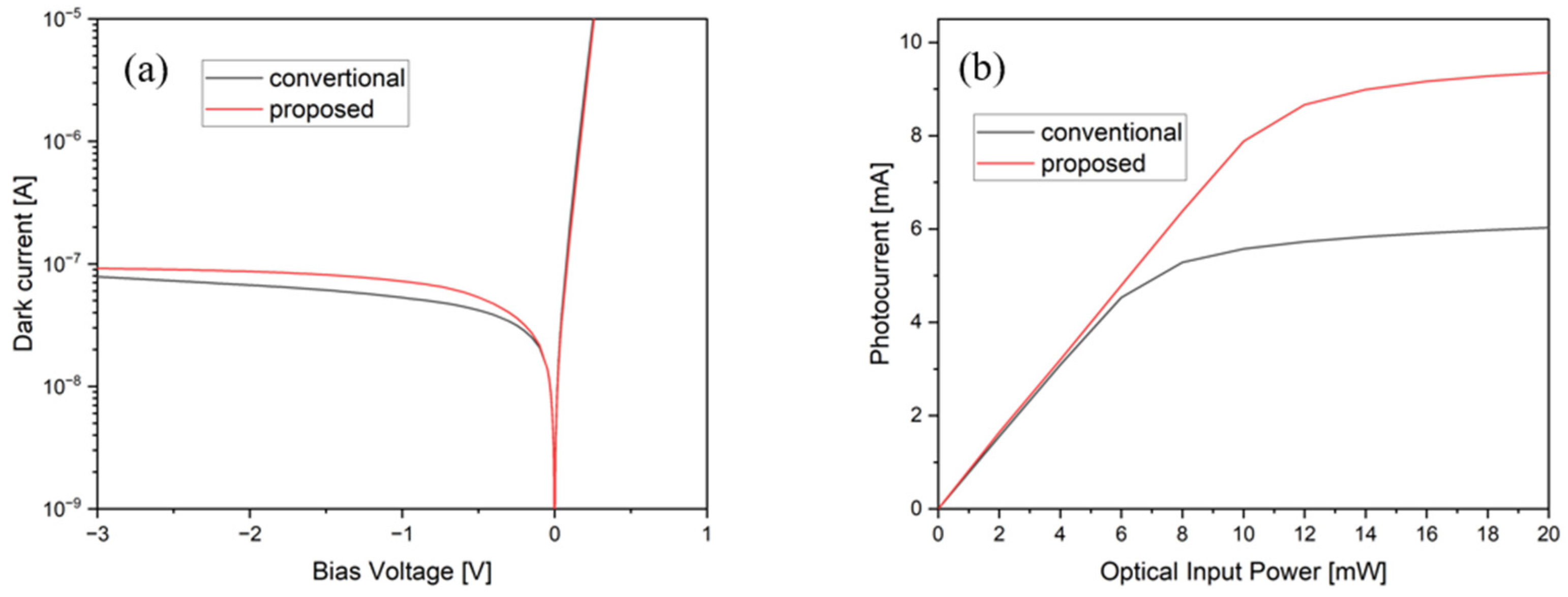
The dark current of both structures were simulated from −3 V to 1 V bias [Figure 2a]. The Shockley–Read–Hall lifetime in the Ge material was set to 1.5 ns. The surface recommendation velocity on the interface between the Ge epitaxial layer and the Si slab was set to 50,000 cm / s . The surface recommendation velocity on the interface between the Ge epitaxial layer and S i O 2 cladding layer was set to 225,000 cm / s . At −1 V bias, the dark current of the mode-evolution-based coupled detector is 73 nA, slightly higher than the 53 nA of conventional one. The dark current of waveguide photodetectors has two origins [20]. One is the junction bulk leakage current due to the defects induced by a lattice mismatch between Ge and Si or by an ion implantation process. The other is a surface leakage current, such as a trap-assisted tunneling current. The slightly higher dark current of the proposed structure arises from the larger surface area.
To compare the linearity of two detectors with different coupling scheme under high-input power, the photocurrent was simulated as a function of the input power to both structures at 1550 nm-λ with a −1 V bias (Figure 2b). It could be observed that there were almost no saturation effects for both coupling structures up to an input power of 6 mW. After the input power exceeds 6 mW, a photocurrent saturation is observed in the conventional butt-coupled detector, while the proposed mode-evolution-based coupled detector continues to maintain high linearity until an input power of 10 mW. At 20 mW of input power, the proposed detector produces a 9.4 mA photocurrent, while the same-sized conventional detector produces a 6.0 mA photocurrent, corresponding to an improvement of 53%. Thus, compared with the conventional butt-coupled detector, the proposed mode-evolution-based coupled detector can effectively alleviate the space-charge effect and increase the saturation photocurrent by improving light field uniformity.
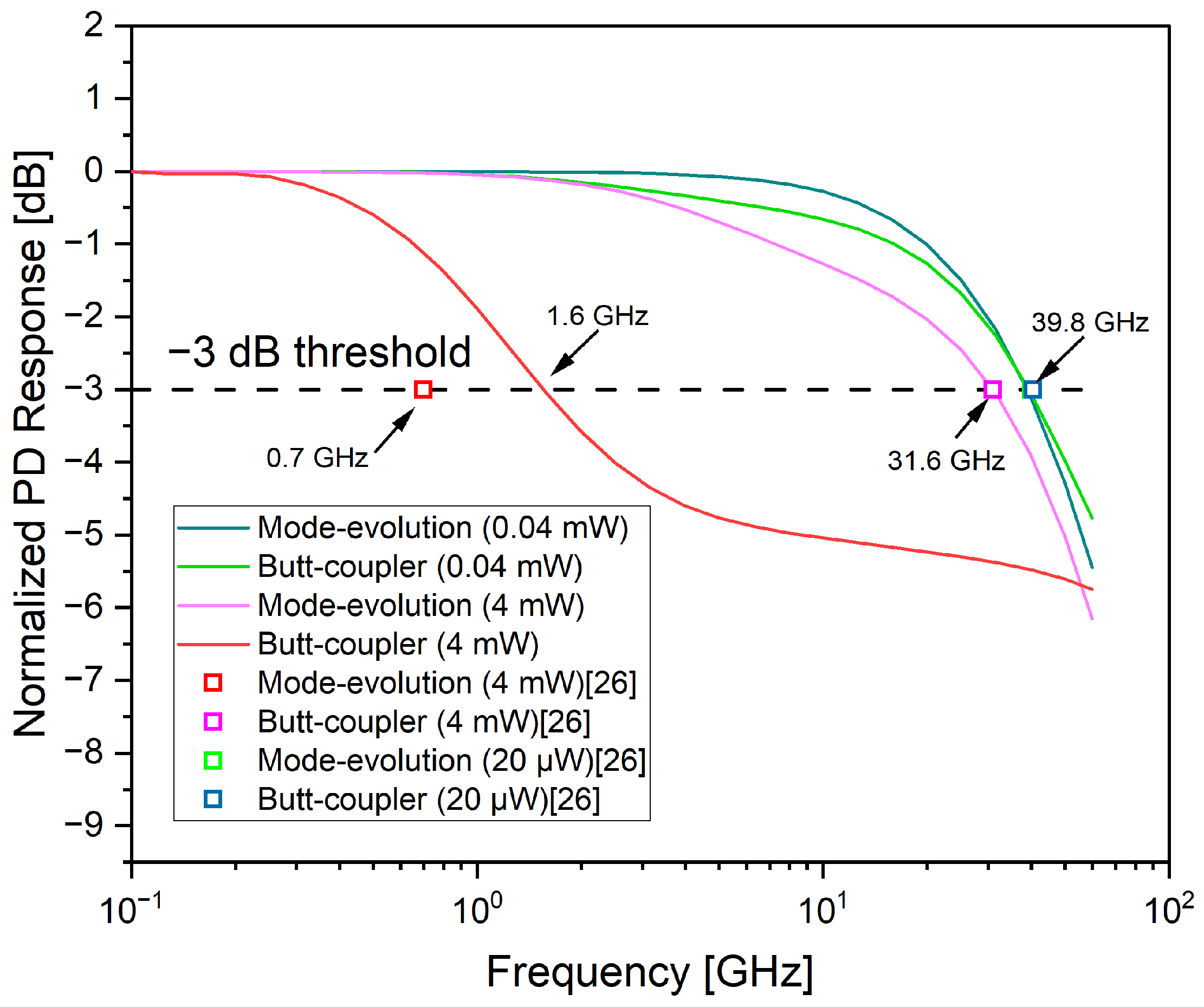
The opto-electrical bandwidth of both types of photodetectors was simulated under the input power of 40 and 4 mW, respectively at −1 V bias. The incident light was TE-polarized, and the wavelength was set to 1550 nm. The calculations were carried out using the commercial software Lumerical, and the three-dimensional (3D) finite-difference time-domain (FDTD) method was used to characterize the optical performance, while CHARGE was used to obtain the electric performance with the three-dimensional (3D) scheme to simulate the non-uniformity of the photogenerated electron-hole pairs along the light propagation direction. Figure 3 illuminates the simulated results. At a low optical input power of 40 μ W for both structures, a bandwidth of 39.8 GHz was observed in both the butt-coupled and mode-evolution-based coupled detectors. When the input optical power was increased to 4 mW, the bandwidth of the butt-coupled detector decreased to 1.6 GHz, whereas the proposed mode-evolution-based coupled detector still maintained a bandwidth of 31.6 GHz. The experimented 3 dB bandwidth has been reported in the previous literature [26], which are marked with boxes in Figure 3 for comparison. The red and magenta boxes indicate the bandwidth with 4 mW of input power, which is 0.7 GHz and 31 GHz for the mode-evolution and butt-coupler, respectively. The green and dark blue boxes indicate the bandwidth with 20 μW of input power, which is 40 GHz for both structures. The simulated results are close to the experimented results reported in the literature, which indicates that the simulation is reliable. The bandwidth improvement is due to the more uniform distribution of the light field in the whole Ge absorption regions, which alleviates the local strong absorption, thus reducing the field screening effect [12] in the butt-coupled detector. The limitation mechanism of the bandwidth will be further discussed in the next section using an equivalent circuit model.
We further investigated the process tolerance of the photodetectors. The selective epitaxial growth process of Ge will induce slanted sidewalls. The sidewall angle may affect the current response of the detector. The simulated results are shown in Figure 4a when the sidewall angle decreases from 90 to 70°, and the current response is reduced by 25.4%. The gap width between the Ge-on-Si absorption regions and bilateral couplers is another factor that may affect the performance of the photodetector. The 100 nm gap width may induce difficulties in the fabrication process. Therefore, we simulated the photocurrent response as a function of gap width, as shown in Figure 4b. The results show that the change in gap width will not significantly affect the photocurrent response. We analyzed that when the gap width approaches zero, the structure proposed by us will approach the structure reported in the literature [9].

3.2. Equivalent Circuit Model

An equivalent circuit model can characterize the frequency response and impedance of photodetectors. The equivalent circuit of waveguide-integrated p-i-n photodetectors was first proposed in 2002, which involves both the carrier-transit effects and the resistive-capacitive (RC) time constant limitation on the frequency response of the pin photodetectors [29]. After that, a number of research works [30,31,32,33,34,35] have demonstrated how to use modified equivalent circuit models to study the performance of photodetectors. Furthermore, an accurate and easy-to-use circuit model is critical in the designing of photonic-integrated circuits (PICs) with electronic design automation (EDA) tools because the conventional electromagnetic simulation method is too time-consuming as the dimension of the PICs becomes larger, while in the equivalent circuit model, detailed physics is abstracted into the component parameters and topological structures of the equivalent model, which avoids numerical analysis and physical equation solving, thus reducing the simulation time significantly.
Figure 5a shows the cross-section of the proposed bilateral mode-evolution-based coupled photodetector, as well as its equivalent circuit model. The structure parameters and the doping concentrations are illuminated in Section 2. The current source represents the photogenerated carriers. R j is the junction resistance and mainly reflects the resistance of the Ge absorption regions. C j is the junction capacitance and is affected by the bias voltage. C j , R j and the current source correspond to the two symmetrical Ge absorption regions. R S is series resistance and is mainly affected by the doping concentration in the silicon slab. Due to the symmetry of the devices, the structure of the whole equivalent circuit is also symmetrical. The node in the middle of the equivalent circuit is connected to the P-port through an Ohmic contact on the Si slab, while the bilateral equivalent circuits corresponding to the Ge absorption regions are both connected to the N-port through the Ohmic contacts on the Ge absorption regions. Both the Ohmic contact with Si and the contact with Ge are incorporated into the series contact R S . It can be seen from the equivalent circuit diagram that the C j on two sides are parallel, and the R S and R j on two sides are also parallel. The capacitance doubling after the parallel connection and the resistance halving after the parallel connection are just complementary. Therefore, the RC bandwidth is not reduced due to the larger junction capacitance introduced by the doubled Ge area. Finally, it should be noted that the parasitic effects due to the pads and interconnects are not included in our equivalent model because they are related to the packaging processing, need to be measured experimentally and do not affect the advantages of the structural innovation proposed by us.
To determine the values of the components in the equivalent circuit, a parameter extraction from the simulation of two-port S 22 parameter was performed. A small signal AC analysis of the proposed bilateral mode-evolution-based coupled detector was carried out in the Lumerical CHARGE modules. By applying an AC voltage of 0.001 V to the −1 V DC bias of P-port, the reflection coefficient ( S 22 parameter) of detector can be obtained. The S 22 parameter can reflect the impedance of the photodetector, and the load impedance was set to 50 Ω as the nominal characteristic impedance. Figure 5b shows the simulated S 22 parameter versus the frequency (from 100 MHz to 60 GHz) of the bilateral mode-evolution-based coupled photodetector on the Smith chart. It can be seen from Figure 5b that the real part of the S 22 parameter, which represents the resistive component, decreases with the increase in frequency, while the imaginary part of the S 22 parameter is negative and represents the capacitive component, whose absolute values first decrease then increase with the increase in frequency.
A genetic algorithm was used to extract the parameter values of the components in the equivalent circuit model by fitting the model parameters to the simulated S 22 parameter. A genetic algorithm is an optimization algorithm inspired by the Darwinian theory of evolution [36]. Every solution corresponds to a chromosome, and each parameter represents a gene. The fitness of each individual is represented by the fitness (objective) function. Through reproduction, crossover and mutation operations, the solutions with higher fitness are preserved. After many generations of iterations, the optimal solution is obtained. The fitness function is defined as the error between the simulated impedance of the photodetector and the iterative values. The latter can be derived from its analytical expression as follows:
Z P D = 1 2 R s + R j + j ω C j R j R s 1 + j ω C j R j ,
where ω = 2 π f is angular frequency. Table 1 shows the extracted component values in the equivalent circuit at −1 V bias voltage. The extracted values are close to the reported results in the previous literature [31], which are obtained by fitting from the experimented results. Therefore, we believe the extracted values of components are convincing.
Based on the determined equivalent circuit, we analyzed the limiting factors that affect the bandwidth of the photodetector. The 3 dB bandwidth is defined as the frequency range from DC to the cut-off frequency f 3 d B , i.e., the frequency at which the electrical output current drops by 3 dB below the current value at very low frequency. The 3 dB frequency depends on both the carrier transit time and RC time constant. The carrier transit time limited bandwidth, which is defined as the time for photogenerated electrons or holes to travel from where they are generated to the collecting electrode, can be expressed as:
f t = 3.5 v 2 π d .
Substitute the carrier saturation velocity v = 6.5 × 10 6 cm / s into the above equation, and take the transit distance d = 0.5   μ m ; it can be calculated that the carrier transit time limited bandwidth is 57.2 GHz. The RC time constant limited bandwidth can be determined using the equivalent circuit model. The transfer function of the circuit model with respect to the input and output currents is written as:
H ( ω ) = i L ( ω ) i S ( ω ) = 2 R L R j j ω C j R j ( 2 R L + R S ) + R S + R j + 2 R L ,
where R L is the load resistance, and i L and i S are the current through the load and the source current, respectively. H ( ω ) is a first-order low-passed filter. The RC time constant limited bandwidth can be derived from the transfer function H ( ω ) as follows:
f R C = R S + R j 2 π C j R j R S ,
where the load resistance is set to 0   Ω because the small signal analysis is carried out under open-circuit conditions. Substitute the extracted component values obtained above, and it can be calculated that the RC time constant limited bandwidth at −1 V bias and 10 mW of optical input power is 25.9 GHz. The 3 dB bandwidth including both of the limiting factors can be written as [33]:
1 f 3 d B 2 = 1 f t 2 + 1 f R C 2 .
Therefore, the 3 dB bandwidth of the proposed bilateral mode-evolution-based coupled photodetector is calculated as 24.6 GHz at −1 V bias and 10 mW of optical input power. Due to the compact size of the detector, the carrier transit time is small, and the main limiting factor of the bandwidth is the RC time constant.
Finally, the comparison between the high-power Ge PDs in the literature and our proposed structure is shown in Table 2. It can be seen that the photodetector with the bilateral mode-evolution-based coupler proposed by us achieves good performance in high-power photodetectors. The small dark current is mainly a result of the compact size. The large bandwidth and responsivity is due to the structural innovation. The maximum current seems to be slightly worse, but the bias voltage in the previous literature is higher than ours. If the bias voltage is increased, the maximum current will be improved.

4. Conclusions

We proposed a novel structure of a high-power Ge-on-Si photodetector, which adopts a bilateral mode-evolution-based coupler to make the light be absorbed along the whole Ge-on-Si structure uniformly. Furthermore, compared with the conventional waveguide photodetector, the doubled Ge regions reduce the optical power per unit volume. Both these structural improvements alleviate the local photogenerated carrier accumulation and reduce the space-charge effects. The results show that the detector has a dark current of 72 nA, responsivity at 1550 nm of 0.8 A/W and a 3-dB opto-electrical bandwidth of 39.8 GHz. The proposed detector with the bilateral mode-evolution-based coupler maintains these characteristics at high illustration, whereas strong saturation effects are observed in the conventional butt-coupled photodetectors. Specifically, the mode-evolution-based coupled photodetector generates a photocurrent of 9.4 mA at 20 mW of optical input power, compared to the 6 mA generated by the conventional butt-coupled photodetector. The proposed photodetector has a bandwidth of 31.6 GHz at 4 mW of optical input power, compared with the bandwidth of 1.6 GHz in the butt-coupled photodetector. The proposed structure shows 53% more photocurrent generation and more than 19 times the opto-electrical bandwidth compared with conventional structures. Furthermore, an equivalent circuit model was proposed to investigate the limiting factors of bandwidth. It was determined that the RC time constant is the main limiting factor for bandwidth rather than the carrier transit time. The characteristics of the proposed photodetector indicate that the novel structure of the Ge-on-Si photodetector is suitable for application in microwave photonics, optical communications and optical sensing where high-power and high-speed photodetectors are desired.

Author Contributions

Conceptualization, D.L.; methodology, D.L.; software, D.L.; validation, D.L.; formal analysis, D.L.; investigation, D.L.; resources, D.L. and Z.L.; data curation, D.L.; writing—original draft preparation, D.L.; writing—review and editing, D.L, Y.Y., X.O., F.S. and Z.L.; visualization, D.L. and X.O.; supervision, Y.Y. and Z.L.; project administration, Y.Y., B.L., B.T., P.Z. and Z.L.; funding acquisition, Y.Y. and Z.L. All authors have read and agreed to the published version of the manuscript.

Funding

This research was funded by the National Key Research and Development Program of China (grant numbers 2018YFB2200203, 2022YFB2802400) and the National Natural Science Foundation of China (grant numbers 61904196, 62274179, 62235001).

Institutional Review Board Statement

Not applicable.

Informed Consent Statement

Not applicable.

Data Availability Statement

The data presented in this study are available on request from the corresponding author.

Acknowledgments

The authors acknowledge Manwen Liu from the Institute of Microelectronics, Chinese Academy of Sciences, China for the helpful assistance and discussion.

Conflicts of Interest

The authors declare no conflict of interest.

References

  1. Marpaung, D.; Yao, J.; Capmany, J. Integrated microwave photonics. Nat. Photonics 2019, 13, 80–90. [Google Scholar] [CrossRef] [Green Version]
  2. Seeds, A.J.; Williams, K.J. Microwave Photonics. J. Light. Technol. 2007, 24, 4628–4641. [Google Scholar] [CrossRef]
  3. Marpaung, D.; Roeloffzen, C.; Heideman, R.; Leinse, A.; Sales, S.; Capmany, J. Integrated microwave photonics. Laser Photonics Rev. 2013, 7, 506–538. [Google Scholar] [CrossRef] [Green Version]
  4. Zhang, Y.; Yang, S.; Yang, Y.; Gould, M.; Ophir, N.; Lim, A.E.-J.; Lo, G.-Q.; Magill, P.; Bergman, K.; Baehr-Jones, T. A high-responsivity photodetector absent metal-germanium direct contact. Opt. Express 2014, 22, 11367–11375. [Google Scholar] [CrossRef] [PubMed]
  5. Going, R.; Seok, T.J.; Loo, J.; Hsu, K.; Wu, M.C. Germanium wrap-around photodetectors on Silicon photonics. Opt. Express 2015, 23, 11975–11984. [Google Scholar] [CrossRef] [Green Version]
  6. Benedikovic, D.; Virot, L.; Aubin, G.; Amar, F.; Szelag, B.; Karakus, B.; Hartmann, J.-M.; Alonso-Ramos, C.; Roux, X.L.; Crozat, P.; et al. 25 Gbps low-voltage hetero-structured silicon-germanium waveguide pin photodetectors for monolithic on-chip nanophotonic architectures. Photonics Res. 2019, 7, 437–444. [Google Scholar] [CrossRef]
  7. Zeng, X.; Huang, Z.; Wang, B.; Liang, D.; Fiorentino, M.; Beausoleil, R.G. Silicon–germanium avalanche photodiodes with direct control of electric field in charge multiplication region. Optica 2019, 6, 772–777. [Google Scholar] [CrossRef]
  8. Chen, G.; Yu, Y.; Xiao, X.; Zhang, X. High speed and high power polarization insensitive germanium photodetector with lumped structure. Opt. Express 2016, 24, 10030–10039. [Google Scholar] [CrossRef] [Green Version]
  9. Zuo, Y.; Yu, Y.; Zhang, Y.; Zhou, D.; Zhang, X. Integrated high-power germanium photodetectors assisted by light field manipulation. Opt. Lett. 2019, 44, 3338–3341. [Google Scholar] [CrossRef]
  10. Lin, L.; Wu, M.; Itoh, T.; Vang, T.; Muller, R.; Sivco, D.; Cho, A. High-power high-speed photodetectors-design, analysis, and experimental demonstration. IEEE Trans. Microw. Theory Tech. 1997, 45, 1320–1331. [Google Scholar] [CrossRef]
  11. Williams, K.J.; Esman, R.D. Design considerations for high-current photodetectors. J. Light. Technol. 1999, 17, 1443. [Google Scholar] [CrossRef] [Green Version]
  12. Giboney, K.S.; Rodwell, M.J.W.; Bowers, J.E. Traveling-wave photodetector design and measurements. IEEE J. Sel. Top. Quantum Electron. 1996, 2, 622–629. [Google Scholar] [CrossRef]
  13. Li, Z.; Pan, H.; Chen, H.; Beling, A.; Campbell, J.C. High-Saturation-Current Modified Uni-Traveling-Carrier Photodiode With Cliff Layer. IEEE J. Quantum Electron. 2010, 46, 626–632. [Google Scholar] [CrossRef]
  14. Siew, S.Y.; Li, B.; Gao, F.; Zheng, H.Y.; Zhang, W.; Guo, P.; Xie, S.W.; Song, A.; Dong, B.; Luo, L.W.; et al. Review of Silicon Photonics Technology and Platform Development. J. Light. Technol. 2021, 39, 4374–4389. [Google Scholar] [CrossRef]
  15. Hu, T.; Dong, B.; Luo, X.; Liow, T.-Y.; Song, J.; Lee, C.; Lo, G.-Q. Silicon photonic platforms for mid-infrared applications [Invited]. Photonics Res. 2017, 5, 417–430. [Google Scholar] [CrossRef] [Green Version]
  16. Li, M.; Chen, X.; Su, Y.; Wang, X.; Chen, M.; Dai, D.; Liu, J.; Zhu, N.H. Photonic Integration Circuits in China. IEEE J. Quantum Electron. 2016, 52, 1–17. [Google Scholar] [CrossRef]
  17. Reboud, V.; Gassenq, A.; Hartmann, J.M.; Widiez, J.; Virot, L.; Aubin, J.; Guilloy, K.; Tardif, S.; Fédéli, J.M.; Pauc, N.; et al. Germanium based photonic components toward a full silicon/germanium photonic platform. Prog. Cryst. Growth Charact. Mater. 2017, 63, 1–24. [Google Scholar] [CrossRef]
  18. Michel, J.; Liu, J.F.; Kimerling, L.C. High-performance Ge-on-Si photodetectors. Nat. Photonics 2010, 4, 527–534. [Google Scholar] [CrossRef]
  19. Kim, M.; Olubuyide, O.; Yoon, J.; Hoyt, J. Selective Epitaxial Growth of Ge-on-Si for Photodiode Applications. ECS Trans. 2008, 16, 837. [Google Scholar] [CrossRef]
  20. Takenaka, M.; Morii, K.; Sugiyama, M.; Nakano, Y.; Takagi, S. Dark current reduction of Ge photodetector by GeO 2 surface passivation and gas-phase doping. Opt. Express 2012, 20, 8718–8725. [Google Scholar] [CrossRef]
  21. Chen, H.; Verheyen, P.; Heyn, P.D.; Lepage, G.; Campenhout, J.V. −1 V bias 67 GHz bandwidth Si-contacted germanium waveguide p-i-n photodetector for optical links at 56 Gbps and beyond. Opt. Express 2016, 24, 4622. [Google Scholar] [CrossRef] [Green Version]
  22. Zhou, H.; Liow, T.; Tu, X.; Lim, E.; Li, C.; Jia, L.; Huang, Y.; Luo, L.; Luo, X.; Song, J.; et al. Germanium-on-silicon photo-detectors based on tiny micro-disk resonators. In Proceedings of the 2016 Optical Fiber Communications Conference and Exhibition (OFC), Anaheim, CA, USA, 20–24 March 2016. [Google Scholar]
  23. Piels, M.; Bowers, J.E. 40 GHz Si/Ge Uni-Traveling Carrier Waveguide Photodiode. J. Light. Technol. 2014, 32, 3502–3508. [Google Scholar] [CrossRef]
  24. Chang, C.M.; Sinsky, J.H.; Dong, P.; Valicourt, G.D.; Chen, Y.K. High-power dual-fed traveling wave photodetector circuits in silicon photonics. Opt. Express 2015, 23, 22857–22866. [Google Scholar] [CrossRef]
  25. Cui, J.; Li, T.; Yang, F.; Cui, W.; Chen, H. The dual-injection Ge-on-Si photodetectors with high saturation power by optimizing light field distribution. Opt. Commun. 2021, 480, 126467. [Google Scholar] [CrossRef]
  26. Byrd, M.J.; Timurdogan, E.; Su, Z.; Poulton, C.V.; Fahrenkopf, N.M.; Leake, G.; Coolbaugh, D.D.; Watts, M.R. Mode-evolution-based coupler for high saturation power Ge-on-Si photodetectors. Opt. Lett. 2017, 42, 851–854. [Google Scholar] [CrossRef]
  27. Watts, M.; Haus, H. Integrated mode-evolution-based polarization rotators. Opt. Lett. 2005, 30, 138–140. [Google Scholar] [CrossRef]
  28. Snyder, A.W.; Love, J.D. Optical Waveguide Theory; Springer: Berlin/Heidelberg, Germany, 1983. [Google Scholar]
  29. Wang, G.; Tokumitsu, T.; Hanawa, I.; Sato, K.; Kobayashi, M. Analysis of high speed p-i-n photodiode S-parameters by a novel small-signal equivalent circuit model. IEEE Microw. Wirel. Compon. Lett. 2002, 12, 378–380. [Google Scholar] [CrossRef]
  30. Choi, W.; Shin, M.; Lee, J.; Zimmermann, L. Equivalent Circuit Models for Silicon Photonics Devices. In Proceedings of the 2016 Asia Communications and Photonics Conference (ACP), Wuhan, China, 2–5 November 2016. [Google Scholar]
  31. Lee, J.-M.; Cho, S.-H.; Choi, W.-Y. An Equivalent Circuit Model for a Ge Waveguide Photodetector on Si. IEEE Photonics Technol. Lett. 2016, 28, 2435–2438. [Google Scholar] [CrossRef]
  32. Lee, M.; Kang, H.; Choi, W. Equivalent Circuit Model for Si Avalanche Photodetectors Fabricated in Standard CMOS Process. IEEE Electron Device Lett. 2008, 29, 1115–1117. [Google Scholar] [CrossRef]
  33. Li, J.; Xiong, B.; Sun, C.; Miao, D.; Luo, Y. Analysis of frequency response of high power MUTC photodiodes based on photocurrent-dependent equivalent circuit model. Opt. Express 2015, 23, 21615. [Google Scholar] [CrossRef]
  34. Dai, D.; Chen, H.-W.; Bowers, J.E.; Kang, Y.; Morse, M.; Paniccia, M.J. Equivalent circuit model of a waveguide-type Ge/Si avalanche photodetector. Phys. Status Solidi 2010, 7, 2532–2535. [Google Scholar] [CrossRef]
  35. Zhan, X.; Liu, Q.; Wang, Y.; Tian, H.; Hu, A.; He, X.; Guo, X. Coupled Equivalent Circuit for High-Speed Photodiodes. IEEE Electron Device Lett. 2019, 40, 1654–1657. [Google Scholar] [CrossRef]
  36. Mirjalili, S. Evolutionary algorithms and neural networks. In Studies in Computational Intelligence; Springer: Berlin/Heidelberg, Germany, 2019; Volume 780. [Google Scholar]
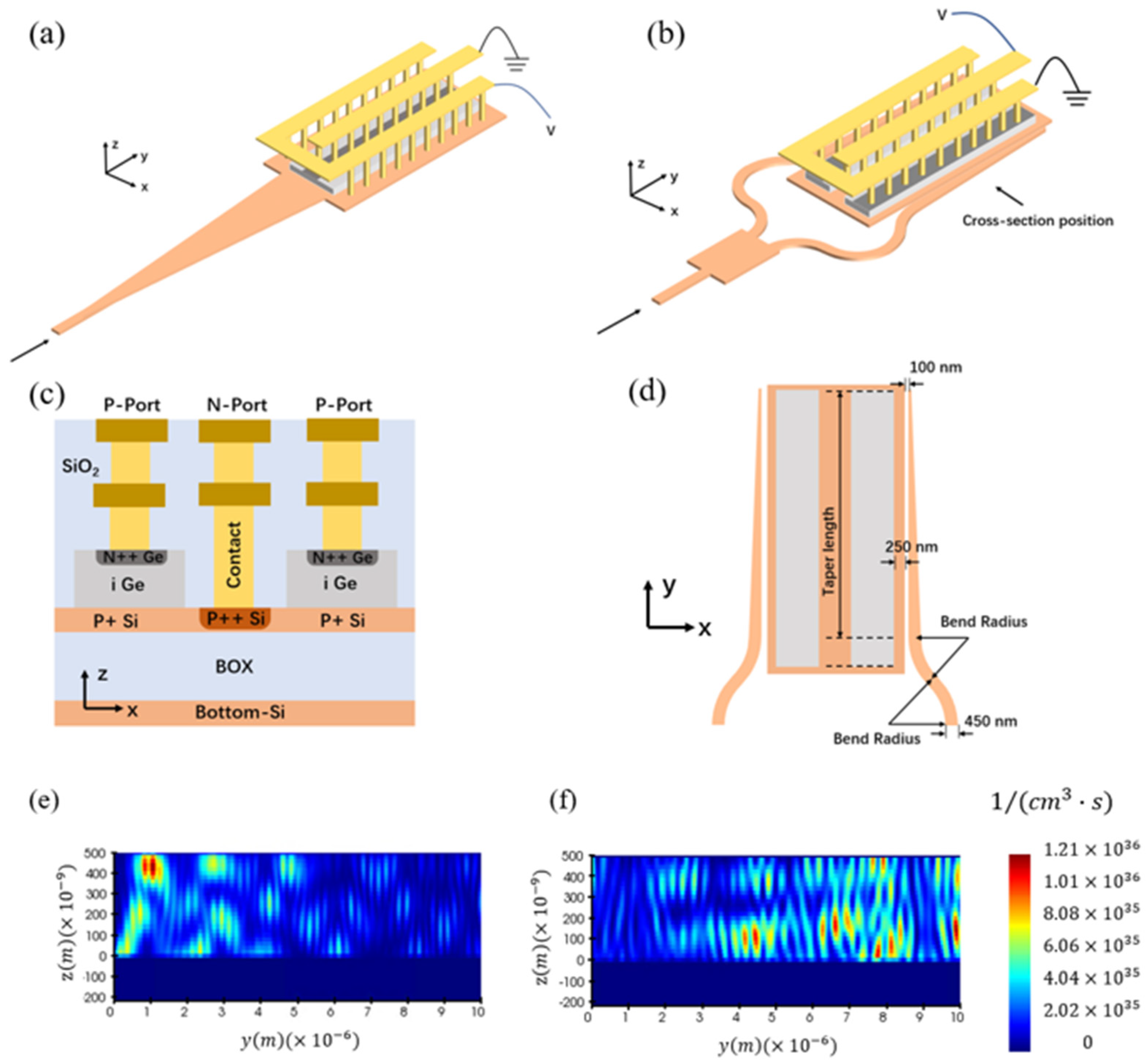
Figure 1. Perspective view of (a) the conventional butt-coupled detector with 50 μ m -long taper and (b) the proposed mode-evolution-based coupled detector. (c) The cross-section of the proposed structure taken in the absorption region. (d) The top-view of the proposed structure, where the electrodes are omitted. (e,f) show the optical generation rate (photogenerated electron-hole pair density per unit time) comparison in the absorption region of (e) the conventional butt-coupled detector and (f) the proposed mode-evolution-based coupled detector.
Photonics 10 00142 g001
Figure 2. (a) The simulated dark current of conventional and proposed detectors. (b) The simulated photocurrent as a function of 1550 nm TE-polarized input power to the conventional and proposed detectors, under −1 V bias voltage.
Photonics 10 00142 g002
Figure 3. Simulated frequency response of the proposed mode-evolution-based coupled detector and the conventional butt-coupled detector at 40 μ W and 4 mW total input power. The 3 dB bandwidth of both structures reported in the literature [26] are marked with boxes in the figure. The green box and the blue box almost coincide, so only the blue box can be seen in the figure.
Photonics 10 00142 g003
Figure 4. The simulated photocurrent as a function of (a) sidewall angle and (b) gap width; the input power is set to 10 mW at 1550 nm wavelength, and the bias voltage is −1 V.
Photonics 10 00142 g004
Figure 5. (a) The proposed equivalent circuit model of mode-evolution-based photodetector. (b) The simulated reflection coefficient ( S 22 parameter) versus frequency (from 100 MHz to 60 GHz) of mode-evolution-based coupled photodetector with 10 mW input optical power and −1 V bias voltage.
Photonics 10 00142 g005
Table 1. Extracted parameters of components in equivalent circuit.
−1 V Bias
R S [ Ω ] 84
R j [ k Ω ] 1.396
C j [ fF ] 24.1
Table 2. Comparison of the high-power Ge PDs in the literature and our work.
BandwidthResponsivity Maximum
Current
Dark Current Reference
35.84 GHz @−3 V and 0.42 mA1.06 A/W @−3 V28.8 mA @−3 V1.82 μA @−3 V[8]
32.5 GHz @−3 V and 0.3 mA0.76 A/W @−3 V112 mA @−3 V59.2 μA @−3 V[24]
20.4 GHz @−3 V and 0.5 mA0.8 A/W @−3 V27.1 mA @−3 V1.41 μA @−3 V[9]
40   GHz   @ 1   V   and   4   μ W 1.0 A/W @−1 V>16 mA @−1 V1.16 nA @−1 V[26]
39.8   Ghz   @ 1   V   40   μ W 0.8 A/W @−1 V9.4 mA @−1 V 72 nA @−1 VThis work
Disclaimer/Publisher’s Note: The statements, opinions and data contained in all publications are solely those of the individual author(s) and contributor(s) and not of MDPI and/or the editor(s). MDPI and/or the editor(s) disclaim responsibility for any injury to people or property resulting from any ideas, methods, instructions or products referred to in the content.