1. Introduction
The nuclear first excited state in
Th is in the focus of nuclear as well as atomic physics research. Due to its low excitation energy in the range of ≈8.2 eV (we took the mean value of the two most recent energy determinations [
1,
2]), the first nuclear excited state plays an exceptional role with the possibility to be excited by laser light. This led to the proposal to use the
Th nucleus as a basis for a nuclear optical clock [
3]. It has been predicted that a nuclear clock could potentially reach a relative frequency uncertainty in the range of
[
4]. Therefore, such a nuclear clock could complement current atomic clocks. It could especially be employed in the search for new physics beyond the standard model [
5].
The reader is referred to the references [
6,
7,
8] for a detailed overview of the topic.
The exceptionally low excitation energy plays an important role when one considers the possible decay channels of the isomer: The isomer potentially decays to its ground state via four decay channels:
decay, internal conversion (IC), bound internal conversion (BIC) [
9] and electronic bridge (EB) [
10]. In the gamma decay channel, the isomer decays by emitting a photon that carries the excitation energy. The partial lifetime of this decay channel has been predicted to be in the range of
to
s [
11,
12].
The
-decay channel competes with the internal conversion decay channel, whose lifetime has been measured in neutral atoms to be in the range of several microseconds [
13], making it orders of magnitude faster than the
decay. During the internal conversion decay, the energy of the isomeric state is transferred to the electronic shell and an electron is emitted into the vacuum. A prerequisite for the IC decay to occur is that the binding energy of one of the bound electrons (which is given by the ionization potential) is below the isomeric excitation energy. For the specific case of
Th, the IC decay is already energetically forbidden for
Th
ions with an ionization potential of ≈12 eV.
Another possible decay channel is bound internal conversion, where the decay energy is also transferred to the electronic shell. Instead of an electron being emitted, as in the internal conversion decay, an electronic state is excited. A requirement for electronic bridge decay is the presence of a transition in the electronic shell that is in resonance with the isomeric ground-state transition. This strong requirement is relaxed in the electronic bridge channel, where the isomer decays by exciting a virtual state in the electronic shell, which subsequently decays to a real electronic state. The excess energy is then carried away in the form of photons.
In the following, we focus on prospects to measure the radiative decay channel in a new setup currently being arranged at LMU Munich.
2. Towards Radiative Lifetime Measurements
For the measurement of the radiative lifetime it is envisaged to monitor the number of Th ions in the isomeric state Th over time. The measurement of the radiative lifetime requires the complete suppression of all the other competing decay channels, such as internal conversion and bound internal conversion. The suppression of internal conversion can be achieved by preventing Th ions from neutralizing, since IC is energetically forbidden in Th ions. Therefore, the ions are confined in an ion trap. The trap is operated under cryogenic conditions to achieve the high vacuum quality that is needed to realize long storage times in the range of the expected radiative lifetime.
The appearance of BIC and EB can be excluded by measuring the lifetime in different electronic states. For a successful measurement of the lifetime, the storage time of the Th ions (the m in brackets indicates that we are dealing with a cloud of ions in the nuclear ground state and the nuclear isomeric state) in the ion trap needs to be at least in the range of the expected lifetime, i.e., several 1000 s. This requires optimum vacuum conditions that can only be achieved under cryogenic conditions at temperatures around 4 K.
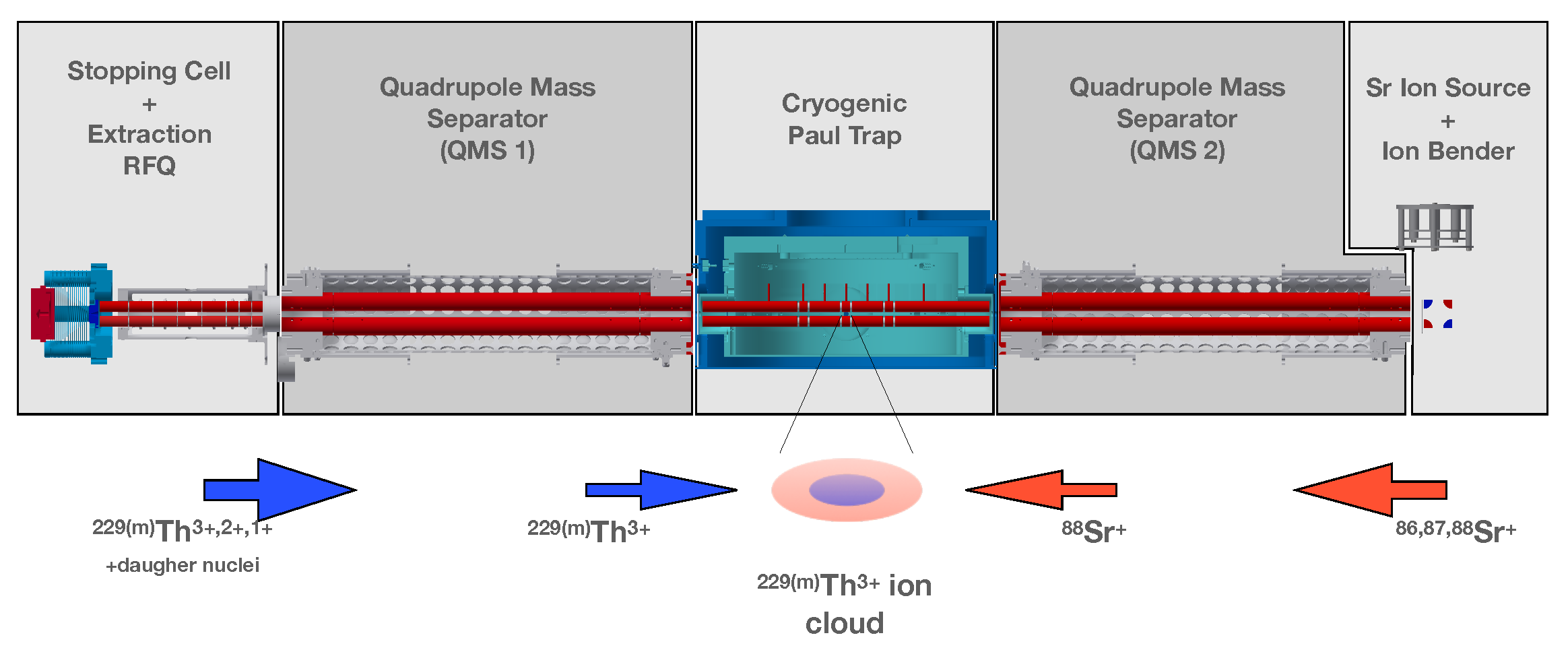
The general concept of the setup is shown in
Figure 1.
Th
ions extracted from a buffer gas stopping cell are loaded axially (from the left side in
Figure 1) into a cryogenic linear Paul trap.
Th
ions are used due to their favorable electronic level scheme exhibiting a rather simple alkali-like structure of an inert Rn core and a single valence electron, providing a closed three-level Lambda system suitable for for laser excitation and fluorescence detection. There, they are sympathetically cooled by
Sr ions, which are provided by an ion source and are axially loaded into the same linear Paul trap from the opposite side (i.e., the right side in
Figure 1).
The Sr ion source is placed 90° off axis, and the ions are bent by 90° using an electrostatic bending quadrupole in order to prevent the cryogenic stages from being exposed to the heated ion source and thereby reducing the heat load to the cold stages. This geometry also allows for a direct line of sight along the central axis of the setup (e.g., to align lasers along the axis for Doppler cooling and spectroscopy).
2.1. Stopping Cell and Extraction RFQ
Th ions are produced in the decay of U, where the isomeric state is fed by a 2% decay branch. For this reason, a U recoil source with an activity of 10 kBq is placed in a buffer-gas stopping cell. The source consists of a Si wafer disk with a diameter of 30 mm. U is deposited onto the disk by electroplating. Th ions leaving the source material with a kinetic energy of ≈84 keV are stopped in 32 mbar catalytically purified helium. The ions are guided by an RF-DC funnel towards a de-Laval nozzle (nozzle diameter ∅ = 0.4 mm) that connects the high-pressure stopping cell to another vacuum chamber.
The RF-DC funnel consists of concentrically stacked ring electrodes, whose inner diameter is reduced linearly with the distance from the source, thus, creating a funnel-like shape. A DC gradient along the funnel electrodes guides the ions axially towards the de-Laval nozzle. Sinusodial RF-fields that are varying in phase by 180° between neighboring funnel electrodes prevent the ions from hitting the electrodes. The electrical potentials together with the funnel-like geometry allow the transport of ions that are far from the central axis towards the nozzle exit.
In the vicinity of the de-Laval nozzle, a gas flow drags the ions through the nozzle and injects them into the subsequent chamber. The formed supersonic gas jet is generated by a pressure difference between the buffer-gas stopping cell (typically at 32 mbar) and the subsequent chamber, which is typically pumped to a pressure in the range of – mbar.
This chamber houses an axially segmented radio-frequency quadrupole (RFQ). A voltage gradient along the axis drags the ions through the remaining buffer gas, while the applied RF voltage keeps the ions on the central axis. This enables the formation of a cooled ion beam.
2.2. Quadrupole Mass Separators
The setup contains two quadrupole mass separators (QMS 1 and 2). QMS 1 is used to generate an isotopically pure Th ion beam that can be injected into the Paul trap and is located between the extraction RFQ and the cryogenic Paul trap. The second QMS (QMS 2) is placed between the cryogenic Paul trap and the Sr ion source. QMS 2 serves two purposes: First, it is used to select Sr ions from the ion beam generated by the Sr ion source.
In addition to other naturally occurring Sr isotopes, the ion beam may also contain elements other than Sr (such as K, Rb or Cs) due to the production process of the source. Secondly, QMS 2 can be used to investigate a possible formation of molecules of the Th ions after being trapped in the Paul trap. The QMS modules follow the design of [
14], which was also used in earlier experiments [
1,
13,
15]. In order to achieve the required mass resolving power, the RF-voltage amplitudes are actively stabilized by an FPGA-based circuit. For further details, see [
16].
2.3. Cryogenic Paul Trap
The central structure of the setup is a Paul trap that is designed to be operated at cryogenic conditions. The design of the Paul trap follows closely the design used in [
17,
18]. For further details, see [
16].
2.4. Sr Ion Source and Ion Bender
The Sr ion source is a commercially available heated dispenser ion source. The source is typically heated to a temperature above 1000 °C by applying a current of ≈2.2 A to a heating filament that is part of the source assembly.
The ions that are emitted from the source are extracted and focused by two ring electrodes. An electrostatic ion bender, consisting of four quarter cylinders that form a quadrupole potential, bends the ions by 90° towards QMS 2. Before entering QMS 2, the ions pass three more ring electrodes that help to efficiently inject them into QMS 2.
2.5. Cooling Lasers and HFS Lasers
To resolve the hyperfine-structure (HFS) shifts that are used to distinguish between the nuclear ground and nuclear isomeric state the Th ions need to be cooled.
Direct laser cooling of
Th
has already been achieved [
19]. In our setup,
Th
ions are sympathetically cooled by
Sr ions, whose mass-to-charge ratio (88 u/e) is close to that of
Th
(76.3 u/e). The lack of hyperfine-structure shifts in
Sr ions provides a simpler cooling scheme than for
Th
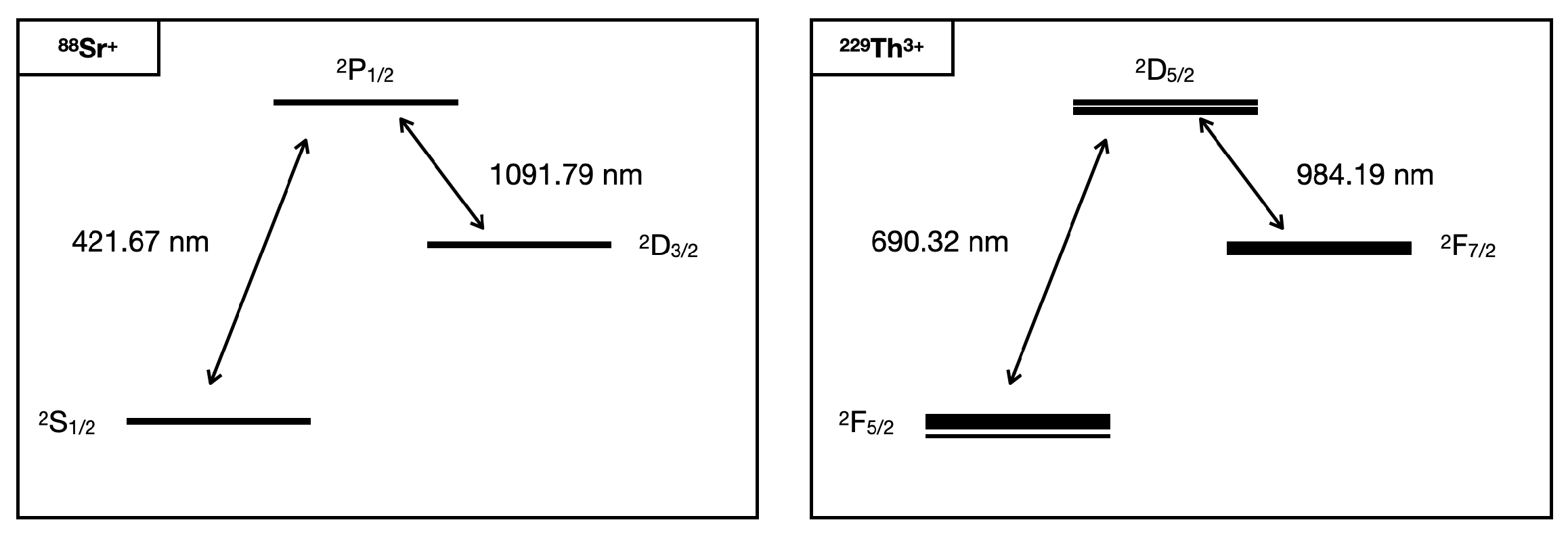
. Doppler cooling can be performed on the
transition at 422 nm [
20]. The ions are re-pumped from the
to the
state with 1091 nm radiation (see the left part of
Figure 2). The discrimination between the nuclear ground state and nuclear isomeric state is performed by measuring the HFS of
Th
.
The HFS will be probed on the
transition at 690 nm. An additional re-pumping laser at 984 nm is needed to pump from the
level back to
. The level scheme is shown in the right panel of
Figure 2.
Th
exhibits a rich hyperfine structure; therefore, in order to avoid pumping into (hyperfine) dark-states, corresponding sidebands are generated with electro-optic modulators (EOMs). All central wavelengths are provided by external cavity diode lasers.
The 422 nm laser is locked to a close-by transition in Rb and shifted with an acousto-optical modulator (AOM) by approximately 440 MHz in order to drive the transition in
Sr [
21]. The remaining lasers will be stabilized by either using a scanning transfer cavity or a commercial wavelength meter.
2.6. Measurement Scheme
The measurement scheme involves two stages. Ions are loaded into the trap and cooled down in a first stage. The second stage involves the measurement of the lifetime. First,
Th
ions are loaded into the trap. The ions are extracted from a buffer gas stopping cell. We estimate the number of extracted ions by scaling the number of
Th
ions extracted from a similar buffer-gas stopping cell and a similar source geometry [
15] with the source activity. In Ref. [
15], the number of extracted
Th
ions was on the order of
ions per second with a source activity of 290 kBq. Therefore, we expect an extraction rate in the range of
ions per second.
This number, however, requires experimental verification, as the exact extraction rate is influenced by several factors, such as the buffer gas cleanliness. We expect a small number of Th ions in the range between 10 and 100 to be loaded into the trap. It is envisaged to form an ion crystal by sympathetic cooling and to identify the nuclear state of the trapped ions by measuring their hyperfine structure. When there is at least one isomer confined in the trap, the lifetime measurement is started. This involves imaging the fluorescence radiation of individual ions onto an (EM)CCD camera.
This allows for identification of the decay of the isomer by tagging ions in the isomeric state on the camera image via their HFS fluorescence and registering their decay to the ground state; the lasers are set to exclusively drive HFS transitions that correspond to the isomeric state. When the isomeric state decays to the ground state, the respective thorium ion turns dark on the camera.
In order to double-check that the ion was not lost due to any other process (i.e., neutralization or molecule formation), the laser is set to drive nuclear ground-state HFS transitions immediately after the ion has turned dark. If the ion is still present in the trap, the time of the decay event can then be recorded and used for data analysis.
It is possible that the isomeric radiative lifetime is affected by the electronic state. For cross-checks, the duty-cycle of the 690 nm laser can be varied. This will leave the ions in the electronic ground-state for a variable amount of time. Additionally, by varying the duty cycle of the re-pumping laser (984 nm), it is possible to pump the ions into the electronic state and investigate the isomeric lifetime for ions in this electronic excited state.


