Review

Laboratory Courses on Laser Spectroscopy and Atom Trapping

Department of Physics & Astronomy, York University, 4700 Keele St. Toronto, ON M3J 1P3, Canada
*
Author to whom correspondence should be addressed.
Atoms 2020, 8(2), 25; https://doi.org/10.3390/atoms8020025
Submission received: 7 April 2020 / Revised: 13 May 2020 / Accepted: 22 May 2020 / Published: 28 May 2020

Abstract

:
We present an overview of experiments covered in two semester-length laboratory courses dedicated to laser spectroscopy and atom trapping. These courses constitute a powerful approach for teaching experimental physics in a manner that is both contemporary and capable of providing the background and skills relevant to a variety of research laboratories. The courses are designed to be accessible for all undergraduate streams in physics and applied physics as well as incoming graduate students. In the introductory course, students carry out several experiments in atomic and laser physics. In a follow up course, students trap atoms in a magneto-optical trap and carry out preliminary investigations of the properties of laser cooled atoms based on the expertise acquired in the first course. We discuss details of experiments, impact, possible course formats, budgetary requirements, and challenges related to long-term maintenance.

1. Introduction

Since the invention of lasers in the 1960s they have been integrated into a myriad of applications, from precision spectroscopy to industrial machining and surgery. As a result, it has become important to offer specialized instructional training opportunities for students and researchers entering these fields. In this paper we discuss a powerful range of educational experiments, organized into two laboratory courses that provide a detailed introduction to laser spectroscopy and atom trapping, and impart the necessary expertise. These courses, which have been operational for thirteen years, have established excellent performance indicators such as reliability of experiments and high rates of completion. The courses were inspired by the robustness of the most commonly used laser-based neutral atom trap, namely a magneto-optical trap (MOT) [1,2]. The simplicity in the design and construction of MOTs has led to their proliferation in research labs. MOTs have become easy to operate, in part due to the improvement in the stability of diode lasers [3,4]. Diode lasers have found widespread commercial use in DVD players, scanners and optical communication, and can be readily adapted for experiments in optical physics [3,4,5,6,7,8,9]. Typically, students entering the third year of study in an undergraduate physics program have a background in electromagnetism, optics, and modern physics. As a result, students can grasp the basic principles involved in understanding and operating a MOT, making laser cooling one of the most popular subjects for research projects. Another reason for this popularity is that the techniques that students learn in this field are widely applicable in other areas such as observational astronomy, experimental particle physics, biological physics, engineering physics and in industrial labs dedicated to research and development in photonics.
The typical upper year undergraduate curriculum at most universities has included classical experiments that allow students to understand and test fundamental principles in physics. At York University, key experiments have included measurements of the speed of light, the inverse square laws in gravitation or electromagnetism, charge quantization, discreteness of atomic energy levels, electron spin resonance, Fourier optics, gamma ray spectroscopy and alpha-particle scattering. These experiments tend to utilize equipment that is generally not used in research labs. Although students learn about pioneering measurements, it was clear that they would benefit from a background that included exposure and training in a research environment using conventional techniques. However, with the proliferation of research labs dedicated to atom trapping, it has been fairly straightforward to provide training in this research area. This development has ensured that students can acquire a thorough background in experimental physics that includes training in advanced data analysis and hands-on skills with contemporary equipment. The technology that has led the development of exciting trends in atomic physics, including MOTs, provides an ideal background.
It is also significant that the laser cooling and trapping of neutral atoms has emerged as one of the most exciting areas of physics during the last two decades, with several Nobel prizes awarded for developments related to this field [10,11,12,13,14,15,16,17,18,19,20,21,22]. Atom traps containing ultra-cold samples with characteristic temperatures of ∼100 μK have resulted in high precision in experiments relating to inertial sensing such as measurements of gravitational acceleration [23,24], gravity gradients [25], and frame rotation [26]. These experiments have inspired the development of portable sensors using cold atoms that can be utilized for oil and mineral prospecting and for correcting tidal charts [27,28,29]. Other fascinating results include precision measurements of the atomic fine structure constant [30,31,32,33], tests of the equivalence principle by measuring the differential acceleration of two laser cooled isotopes [34], measurements of the gravitational redshift [35,36], and low-energy tests of the standard model [37]. Atomic fountain clocks using cold atoms [38,39] have replaced atomic beam based national time standards and are used to synchronize a network of global positioning satellites. The development of a femtosecond frequency comb that can be referenced to an atomic clock has also made it feasible to develop a new generation of frequency standards [40,41]. Trapped atoms have also been cooled to nanokelvin temperatures at which Bose-Einstein condensation (BEC) can be observed [42,43]. Obtaining BEC has made it possible to realize coherent sources of atoms [44,45] and carry out interesting tests of atomic and condensed matter physics at a level considered impossible only a few years ago [46,47]. Recent experiments in which a BEC is dropped over a 100 m path-length have made it possible to consider precision tests of the equivalence principle [48].
This paper provides a detailed overview of instructional experiments adopted to laboratory courses and related to MOTs. We begin with a discussion of the course format in Section 2 and provide a brief overview of home-built diode lasers and tapered amplifiers that can reduce the cost of course development. In Section 3, we discuss details of the experiments related to laser spectroscopy and atom trapping with examples of typical data. The paper concludes with a qualitative discussion of the impact, alternate approaches for course development, challenges related to the training of teaching assistants, and long-term maintenance in Section 4.
A key difference with respect to common themes in other pedagogical papers is that we do not focus on reducing the cost of any single experiment although we describe easier ways of carrying out what can now be regarded as classical experiments in modern atomic physics. In fact, some of the experiments represented here have become available as commercial packages since the time these courses were introduced. Therefore what we emphasize is how the collective impact of a range of techniques from carefully chosen experiments can provide student training appropriate for graduate careers and industrial research positions.

2. Course Format

At York University, two one semester courses, designated as PHYS 4061 (Experimental Techniques in Laser Physics) and PHYS 4062 (Atom Trapping Laboratory), have been part of the curriculum since 2007. The introductory course (PHYS 4061) involves six laboratory hours and two hours of classroom instruction per week and nine experiments related to techniques in atomic physics and laser spectroscopy. The experiments in PHYS 4061 are based on a number of undergraduate research projects [49,50,51,52,53,54,55,56,57,58]. The objective of the course is for students to acquire hands-on experience with conventional equipment and contemporary experimental techniques. Therefore, PHYS 4061 stresses short-form lab reports with an emphasis on data analysis. Although there are a number of platforms for symbolic computation, we have adopted Mathematica since it seems well suited for batch processing and curve fitting [59]. As a result, the course begins with a comprehensive Mathematica tutorial that is spread over four three-hour laboratory sessions. During these sessions, students complete a laser safety tutorial and become familiar with the flash card system for downloading data from oscilloscopes. For the remainder of the course, students work in groups of two and cycle through the spectroscopy experiments on a weekly basis. Each of these experiments has been designed to be completed during two three-hour laboratory sessions.
Topics required to understand these experiments are covered in a variety of upper level physics courses such as electromagnetism, modern physics and quantum mechanics. Additionally, a comprehensive laboratory manual [60] has been developed to cover theoretical concepts associated with each experiment. The lecture component of this course includes twelve lectures that cover theoretical background related to instrumentation such as gas and diode lasers, LEDs, electro-optic and acousto-optic modulators, Fabry-Pérot interferometers, and properties of Gaussian beams. Each lecture is supported by a tutorial that covers the background for experiments. The course has been designed to accommodate 20 students in one section.
PHYS 4062 focuses on atom trapping and allows students to apply skills acquired in PHYS 4061 to trap atoms in a MOT and carry out simple investigations of the properties of laser cooled atoms. The lecture component of PHYS 4062 describes the formalism related to the radiation pressure force, magnetic trapping and the optical dipole force. The tutorials describe techniques relevant to cold atom experiments. Students are provided with two preassembled vacuum chambers for atom trapping that have been pumped down to the required base pressure. This course has a laboratory component amounting to six hours per week for a period of eight weeks. During the last four weeks of the term, students are required to complete a long-form lab report as in traditional laboratory courses.
The student experience in this course closely resembles a research environment with open-ended experiments. Our approach has been different from atom trapping experiments at other universities because it provides students with a greater degree of hands-on experience.
Four of the nine experiments in PHYS 4061 are based on the use of external cavity diode lasers (ECDLs). So far, we have relied entirely on commercial diode laser systems to support these courses. However, we have constructed home-built ECDLs to support course expansion in the future. Graduate teaching assistants have found the commercial systems to be straightforward to maintain since the only requirement is the replacement of laser diodes and re-alignment of the laser head (typically once in five years). However, investment in these systems can have a significant impact on the equipment budget required to set up the courses, as discussed further in this section and Section 4.
ECDLs can be assembled from readily available commercial components from a number of robust and inexpensive designs in References [3,5,7,8,9]. These lasers have specifications that are similar to commercial systems, such as an output power of up to 150 mW and a linewidth of ∼1 MHz. We have built a number of laser heads based on the design in Reference [3], which uses a diffraction grating in the Littrow configuration to provide optical feedback. Additionally, we have developed temperature and current control modules to stabilize the frequency of the ECDL. Home-built lock-in modules for active frequency stabilization have allowed both peak locking and side locking [55]. We have generally relied on commercial function generators to scan the laser cavity using a piezo element attached to a diffraction grating. We have found that the equipment budget for a home-built laser system is about 1/4th of the cost of a similar commercial system, which is approximately $20,000. The home-built lasers have worked reliably in atom trapping experiments conducted in a research laboratory, but require more expertise to maintain than commercial systems.
Based on the design in Reference [61], we have developed a master oscillator power amplifier (MOPA) system that produces an output power of ∼1 W for 1/5th of the commercial cost, which is approximately $30,000. The MOPA relies on an ECDL output of ∼20 mW to seed a semiconductor tapered amplifier. Although the ECDLs provide sufficient power for atom trapping, power limitations due to optical losses and the need for intensities that are large compared to the saturation intensity for atoms (∼1 mW/cm2) can restrict the diameter of the trapping laser beams to a few millimeters.
In recent years, we have had even greater success employing interference filter (IF) stabilized ECDLs (Figure 1), based on the design in Reference [9]. These lasers can be hermetically sealed and pumped down to very low pressures, enabling more stable locking techniques [62,63]. They are suitably stable for measurements of gravitational acceleration using a falling corner cube gravimeter (Scintrex FG5X) [64] and are also easily integrated into the MOPA system for experiments which require greater optical power [65].
The number of atoms that can be loaded into a vapor cell MOT with a laser beam diameter d is known to scale as d x , where x is typically larger than 3 [66]. Therefore, alignment of a MOT can be made easier with large diameter laser beams. A MOPA can be used to provide sufficient power for a suitably large laser beam (>2.5 cm) in order to load a large number of atoms in the MOT and achieve a high signal-to-noise ratio in cold atom experiments. Therefore, the impact of a large beam diameter for experiments in an instructional lab must be considered.
ECDLs and MOPA systems must be protected from optical feedback that can damage both laser diodes and tapered amplifiers. In our experience, home-built Faraday isolators developed on the basis of an undergraduate research project [58] have been cost effective solutions. These devices have provided optical isolation of >20 dB for one third of the commercial cost.

3. Description of Experiments

Four experiments in PHYS 4061 use Rb spectroscopy and ECDLs operating at 780 nm. They involve topics such as absorption and fluorescence spectroscopy, electro-optic modulation, Zeeman shift, laser linewidth, and laser frequency stabilization. We have divided the article into subsections that provide an overview of these experiments with each subsection concluding with remarks about the relevance of these experiments to atom trapping in PHYS 4062. Four additional experiments that involve diode laser modules operating at other wavelengths are then described. These additional experiments are related to optical heterodyne detection, Gaussian beam propagation, optical detectors, and optical tweezers. We then describe a separate experiment that uses a pumping station to introduce vacuum techniques. We also describe how each of the experiments in PHYS 4061 impacts the atom trapping experiments in PHYS 4062. All experiments reviewed in this section provide a suitable background for experiments with atoms in a MOT.
Most of the laser spectroscopy experiments in the course are carried out in Rb vapor at room temperature using ECDLs. The energy level diagrams for the D2-lines in 85Rb and 87Rb are shown in Figure 2a. The Doppler broadened absorption spectrum obtained by scanning the ECDL several GHz over the Rb resonances in a 5 cm long vapor cell at room temperature is shown in Figure 2b. The Doppler widths of the individual transitions (for example, the F = 3 F = 2 , 3 , 4 resonances in 85Rb) can be obtained from background subtracted fits. The calculated FWHM for an isolated two-level atomic system at a wavelength of 780 nm and a temperature of 300 K is 511.2 MHz. It is an interesting exercise to understand this discrepancy using known frequency splittings between individual transitions that contribute to the fitted line shape and the corresponding transition probabilities. The Doppler-free saturated absorption spectrum corresponding to the aforementioned resonance is shown in Figure 2c. A fit to the F = 3 F = 4 resonance is shown in Figure 2d.

3.1. Emission and Absorption Spectroscopy and the Electro-Optic Phase Modulator

Students are introduced to atomic structure and absorption and fluorescence spectroscopy in the first part of the experiment. The two measurement techniques are compared and contrasted. A schematic of the experimental setup is shown in Figure 3. A weak probe beam is scanned across Rb resonances in a vapor cell and the absorption is detected by photodiode A. In this manner, the Doppler broadened absorption spectra from the ground states of 85Rb and 87Rb can be measured. The spectra are fitted using Gaussian functions is shown in Figure 2b. The absorption of a weak probe beam in the presence of a strong counter propagating pump beam is detected by photodiode B showing Doppler-free resonances as shown in Figure 2c. A Lorentzian fit to a single resonance line is shown in Figure 2d.
In a separate experiment, an electro-optic phase modulator (EOM) is placed in the pump laser with the probe beams blocked [52,57]. This commercially available modulator is tuned to a resonance frequency of 2.915 GHz. This value was chosen corresponding to the difference between the F = 3 F = 4 and F = 2 F = 3 transitions in 85Rb, shown in Figure 2a.
In the EOM experiment, the pump beam intensity is fixed and the fluorescence spectra from a detector at an angle of 90° (photodiode C in Figure 3) with respect to the laser beam is monitored. Spectra are recorded with the EOM turned on and off, as shown in Figure 4. New spectral features that are displaced by the operating frequency of the EOM are produced. These features can be used to infer the efficiency of the EOM [52]. In addition, it is an interesting challenge to interpret the relative changes in amplitudes of other spectral lines [52].
This experiment can also be carried out using a home-built EOM with a resonance frequency of ∼20 MHz. The cost of the home-built EOM is approximately one sixth of the cost of the commercial EOM [57]. For experiments with low frequency EOMs, it is necessary to measure Doppler-free absorption spectra (in the presence of pump and probe lasers) to resolve the sidebands.
A comprehensive introduction to atomic level structure, Doppler-free spectra, and cross-over resonances is provided in the manual [60] so that students can interpret the results. A description of the line shapes due to Doppler broadening and natural broadening is also provided. A brief description of electro-optic phase modulation and applications of EOMs is provided in connection with the last part of the experiment.
Knowledge of atomic level structure and frequency shifts of laser beams are crucial for experiments in atom trapping since these experiments require frequency stabilization and frequency tuning of a laser beam with respect to an atomic spectral line. Trapping 85Rb atoms in a MOT requires a trapping laser to rapidly cycle atoms between the F = 3 and F = 4 states and a second (repump) laser to optically pump the F = 2 ground state. The laser frequencies can be derived from the same ECDL using an EOM with an appropriate operating frequency.

3.2. Zeeman Shift

In this experiment, the frequency shift of an atomic transition in Rb is studied as a function of magnetic field strength [67]. The saturated absorption setup shown in Figure 3 is used to observe the Doppler-free Rb spectrum shown in Figure 2c. A solenoid is placed around the Rb vapor cell (see Figure 3) to produce a nearly uniform magnetic field. The laser is scanned over the F = 3 F = 4 atomic resonance as shown in Figure 2a,d. To measure the Zeeman shift of this spectral line, spectra are simultaneously recorded with reference to a separate Rb vapor cell under ambient conditions. This procedure is crucial for eliminating the effect of laser frequency drifts. The magnetic field has been sufficiently large (>1 Gauss) to overwhelm the effect of the Earth’s field, but not large enough (<30 Gauss) to produce level mixing. It is also important to ensure that the circular polarization of both pump and probe beams are set so that they drive the same transition.
An example of the measured Zeeman shift plotted as a function of magnetic field is shown in Figure 5. The slope is consistent with the expected Zeeman shift for the F = 3 , m F = 3 F = 4 , m F = 4 transition. This suggests that a system consisting of seven independent transitions between the F = 3 and F = 4 levels can be modeled by a two level system. We attribute this behavior to two effects [67]. Firstly, for circular polarization, the transition probabilities increase for transitions with higher magnetic quantum numbers. For example, the transition probability for m F = 3 m F = 4 spectral line is 28 times larger than transition probability for the m F = 3 m F = 2 spectral line. Secondly, if the beam diameter is sufficiently large such that the transit time is comparable to the optical pumping time, optical pumping during the scan time of the pump laser can preferentially populate the F = 3 , m F = 3 ground state. It is instructive to record the Zeeman shifts of both Doppler-free and cross-over resonances with different polarization settings for the pump and probe and compare the measured shifts with theory.
It is notable that the narrow laser linewidth and Doppler-free spectroscopy allow the Zeeman shift to be characterized using a small wire-wound solenoid and a compact setup. In contrast, the Zeeman shift is typically studied in upper year laboratories using a discharge lamp source and a large water-cooled solenoid to generate magnetic fields of ∼104 G.
In the final part of the experiment, the dependence of the width of a spectral line on laser intensity is studied. In this case, the width of the Doppler-free resonance is recorded as a function of the pump beam intensity, which is varied by using a λ/2-wave plate and polarizing beam splitter at the entrance of the saturated absorption setup. Alternatively, optical neutral density filters can be introduced into the pump beam. It is possible to infer the natural linewidth of the spectral line as well as the saturation intensity of the transition from this data if the vapor cell is magnetically shielded.
Background concepts related to the Zeeman shift, calculation of Landé g-factors and power broadening are described in the manual. The Zeeman shift is responsible for the restoring force in a MOT. Additionally, the frequency shifts of laser beams used in atom trapping can be controlled by Zeeman shifting spectral lines to which the lasers are locked [67].

3.3. Faraday Isolator and Fabry-Pérot Interferometry

Two separate experiments have been combined into this lab. In the first part, the function of polarizing elements such as linear polarizers and wave plates are reviewed. Linearly and circularly polarized light are distinguished by measuring the transmission through a rotating polarizer attached to a compact motor. Since optical feedback can alter or damage laser diodes, the utility of using an optical isolator consisting of a polarizing cube and λ/4-wave plate to reduce optical feedback is demonstrated. This arrangement reduces optical feedback only for a particular polarization. Subsequently, students align a home-built Faraday isolator [58], a device that eliminates optical feedback for all polarizations. The rotation angle and the isolation ratio of the isolator are measured in the experiment.
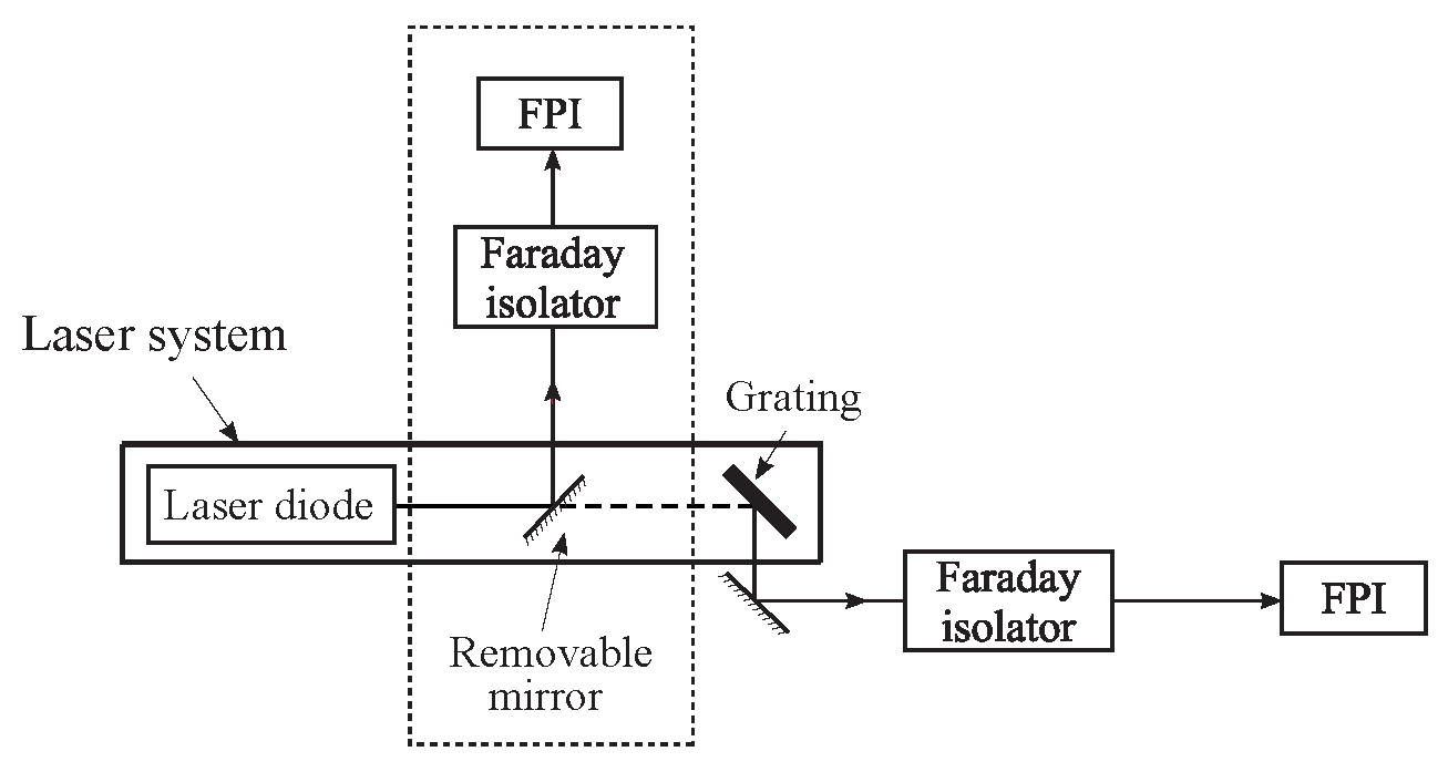
In the second part of the experiment, light from the ECDL (linewidth ∼1 MHz) is sent through a Fabry-Pérot interferometer (FPI) with a resolution of ∼60 MHz. The ECDL grating that provides optical feedback is bypassed so that the linewidth of the laser becomes larger than the FPI resolution. The laser frequency is fixed and the transmission spectrum of the FPI is recorded by scanning the spacing between the cavity mirrors. The linewidth of the free-running laser diode can be estimated from the transmission spectrum of the FPI. The experiment is repeated after the reintroduction of the grating. In this case, the instrument limited resolution rather than the laser linewidth is measured. A schematic of the experiment is shown in Figure 6 and representative FPI spectra are shown in Figure 7. The mode characteristics of the ECDL can also be investigated by varying the diode current and temperature.
The operating principles and design of a Faraday isolator and essential properties of the FPI are reviewed in the lab manual. The students are exposed to the properties and characteristics of narrow linewidth ECDLs that are used for atom trapping.

3.4. Laser Frequency Stabilization and the Lock-In Amplifier

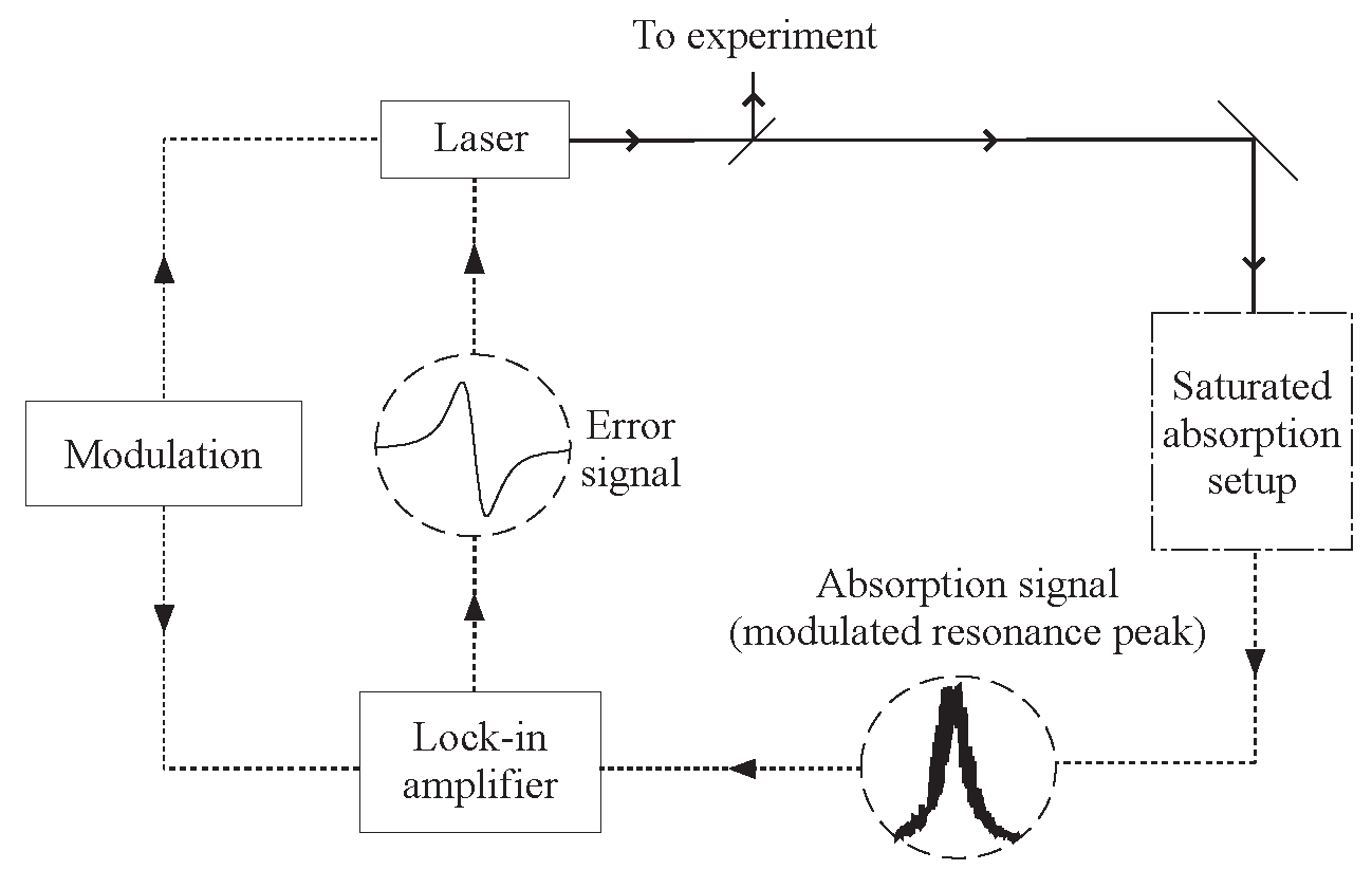
This experiment focuses on the use of a lock-in amplifier for frequency stabilization of a diode laser. The saturated absorption setup used in this experiment is shown in Figure 3. The schematic for the feedback loop required to lock the laser frequency to the peak of an atomic spectral line is shown in Figure 8.
In the first part of this experiment, students are guided through the essential components of a lock-in amplifier, shown in Figure 9. Exercises include studying the performance of a phase shifter and radio frequency (RF) mixer. The phase shifter consists of an analog circuit with a variable resistor that allows the phase shift imposed on an RF waveform to be varied and calibrated. Two RF inputs, consisting of the output of the phase shifter and the modulated absorption signal, are used as inputs to the mixer. The mixer output is verified to scale as the cosine of the phase difference between the two RF inputs.
In the second part of the experiment, a commercial lock-in module attached to the laser controller is used to study the dispersion-shaped error signal shown in Figure 9. For this experiment, the modulated saturated absorption signal and the modulation from a built-in function generator are used as inputs to the lock-in. The dependence of the error signal on lock-in phase is studied by scanning the laser across a suitable atomic resonance, as shown in Figure 10. To lock the laser, the error signal is first minimized by varying the phase, as shown in Figure 10b. The phase is incremented by ±90° to maximize the error signal, as shown in Figure 10a,c. It can be determined that the laser will remain locked for one of these settings and that it will be forced away from resonance for the other setting. To lock the laser, the scan amplitude is reduced and the feedback loop is engaged by sending the error signal to the laser. After locking the laser to a particular spectral line, the frequency stability of the laser is determined by recording the fluctuations in the DC level of the error signal, as shown in Figure 11. This figure also illustrates the frequency excursions of the laser without feedback.
Atom trapping experiments require frequency stabilized lasers to drive specific atomic transitions. The lab manual presents both a physical model of the error signal [49], as well as a more mathematical treatment [55].

3.5. Radio Frequency Components and Optical Heterodyne Detection

Students are introduced to the function of RF components in the first part of this experiment. Simple experiments that utilize a voltage-controlled oscillator (VCO) are used to understand working principles of amplifiers, mixers, power splitters, frequency doublers, and transistor-transistor logic (TTL) switches. For example, students can design a frequency doubler by connecting two outputs of a power splitter into a mixer and filtering out the low frequency component. Other experiments include measuring the frequency range and power output of a VCO and measuring the on/off ratio of RF pulses using a mixer or a TTL switch.
In the primary experiment, a continuous wave (CW) RF signal from an amplifier is used to drive an acousto-optic modulator (AOM). Light from one of the ECDL-based experiments described previously is aligned through the AOM. The first order diffracted beam is rendered co-propagating with the undiffracted beam using a combination of mirrors and a 50/50 beam splitter, as shown in Figure 12a. The undiffracted beam from the AOM serves as an optical local oscillator (LO). A photodiode placed in the path of overlapped beams records a heterodyne beat note at the RF frequency used to drive the AOM. Under typical operating conditions, the intensity of the diffracted beam is comparable to that of the undiffracted beam. If the AOM is driven at low power, the diffracted beam can represent a weak signal. With the LO blocked, the photodiode can be used to detect the signal as a change in intensity. With the LO unblocked, the signal can be detected by the presence of the beat note. Other extensions of this experiment could include studying the size of the beat signal versus the power in the diffracted beam and comparing the smallest signals that can be measured using heterodyne and intensity detection.
The remainder of the experiment involves pulsing the RF signal driving the AOM and recording the diffracted pulse detected by the photodiode. Pulsing the amplitude of the RF signal from a VCO is accomplished using a function generator and a TTL switch, as shown in Figure 12a. The photodiode records a time-delayed optical pulse, as shown in Figure 12b. The envelope of the optical pulse exhibits the heterodyne beat note. The time delay between the trigger pulse used to drive the AOM and the corresponding optical pulse is measured. The distance between the transducer attached to the AOM crystal and the laser beam is recorded. These measurements allow the speed of sound through the AOM crystal to be inferred. The rise time of the diffracted pulse can be used to measure the size of the laser beam passing through the AOM. Additional exercises relating to this experiment could include demonstrations of setting up AOMs in a dual pass configuration [51].
The background covered in the lab manual includes the theory of Bragg diffraction in an AOM and a derivation of the frequency shift of the diffracted beam based on the first order Doppler shift for sound waves. In the atom trapping course, students use an AOM to derive the frequency-shifted trapping laser beam from a diode laser locked to an atomic spectral line. The trapping laser can be amplitude modulated for a range of cold atom experiments.

3.6. Optical Detectors

This experiment is designed to provide a working knowledge of three different optical detectors: photodiodes, photomultiplier tubes (PMT), and charged coupled devices (CCD cameras). In a preliminary experiment, CW light intensity is measured using both photodiodes and PMTs so that the dynamic range, saturation characteristics, and signal-to-noise ratios associated with these detectors can be estimated. Using an AOM, it is also possible to demonstrate pulsed detection. The response time of an optical detector with a 1 MΩ termination resistance is measured. The time constant of the detection system is modified by changing the termination resistor so that the rise time of the optical pulse from the AOM can be measured.
A triggered CCD camera and frame grabber are used to measure the fluorescence generated by an electron beam moving across the phosphor screen of an analog oscilloscope, as shown in Figure 13. The characteristic decay in fluorescence intensity as the beam sweeps across the screen is shown in Figure 14. We find that the decay time of the phosphor coating on the oscilloscope screen is strongly dependent on both the electron beam intensity and the oscilloscope time-base settings. For this measurement, we used an oscilloscope with a P31 phosphor.
Triggering the CCD prepares students for atom trapping experiments since photographing the electron beam fluorescence is analogous to photographing the ballistic expansion of a cloud of laser cooled atoms after turning off the confining forces. CCD imaging is a standard technique used for measuring the temperature of trapped atoms [56]. PMTs and photodiodes are also extensively used in atom trapping. For example, a PMT can be used to measure trap fluorescence and estimate the number of trapped atoms and a photodiode can be used for measuring the absorption spectrum of the cold sample [54].

3.7. Gaussian Beam Propagation and Optical Fiber Coupling

This lab builds on earlier experiments in second year optics where students are introduced to techniques for obtaining the spatial profiles of laser beams. These techniques include scanning a pinhole or knife edge across the profile while measuring the transmitted intensity or measuring the intensity through a series of calibrated apertures centered on the beam. In this paper, all measurements of the spatial profile are carried out using a commercially available scanning knife-edge beam profiler.
In the first part of the experiment, the spatial profile of a focused He-Ne laser is measured along two orthogonal directions perpendicular to the direction of propagation of the laser beam. The measured beam size of a focused laser beam as a function of position is shown in Figure 15a. The Rayleigh range and beam divergence can be determined from fits to the beam profile as a function of the distance from the position of the focus.
The second part of the lab demonstrates how spatial filtering can be used to improve the beam profile. Both pinhole filtering and optical fiber coupling are demonstrated. Since the experiment involves very few optical elements and the laser beam propagates over a limited distance on the optical table, a scratched cover slide is used to distort the beam profile. The effect of spatially filtering this beam using an optical fiber is shown in Figure 15b.
Further appreciation of spatial profiles is emphasized in the atom trapping experiment since the number of atoms that can be trapped in a MOT depends critically on the beam profile.

3.8. Vacuum Components and Pumping Techniques

This experiment provides a working knowledge of some vacuum pumps and pumping techniques. The experimental setup is shown in Figure 16. In the first part of the experiment, students use a roughing pump to pump on a vacuum chamber with a volume of ∼13 L. The pumping speed is investigated with different bellows hose lengths, apertures and leaks. In all these cases, the decrease in the fore line pressure is measured as a function of time using a Pirani gauge and a stopwatch. We find that the change in pressure can be suitably modeled as a decaying exponential immediately after the pump down commences. For the geometry with the highest pumping speed, the transition from the viscous flow regime to the molecular flow regime is estimated to occur for pressures less than 10 mTorr. In the second part of the experiment, the vacuum chamber is pumped using a roughing pump in series with a turbo pump to a pressure of ∼10−6 Torr. The effect of out gassing is illustrated by valving off the turbo pump and by heating parts of the vacuum chamber.
The theoretical background in the laboratory manual includes a discussion of both continuum and molecular flow regimes, mean free path, and the effect of the diameter and the length of a hose on the conductance. The principles of operation of roughing pumps, turbo pumps, diffusion pumps, and entrapment devices such as ion pumps and cryogenic pumps are reviewed. A few common types of pressure gauges are discussed.
This experiment provides a suitable background to understand the conditions in the small volume vacuum chamber used for atom trapping experiments.

3.9. Optical Tweezers

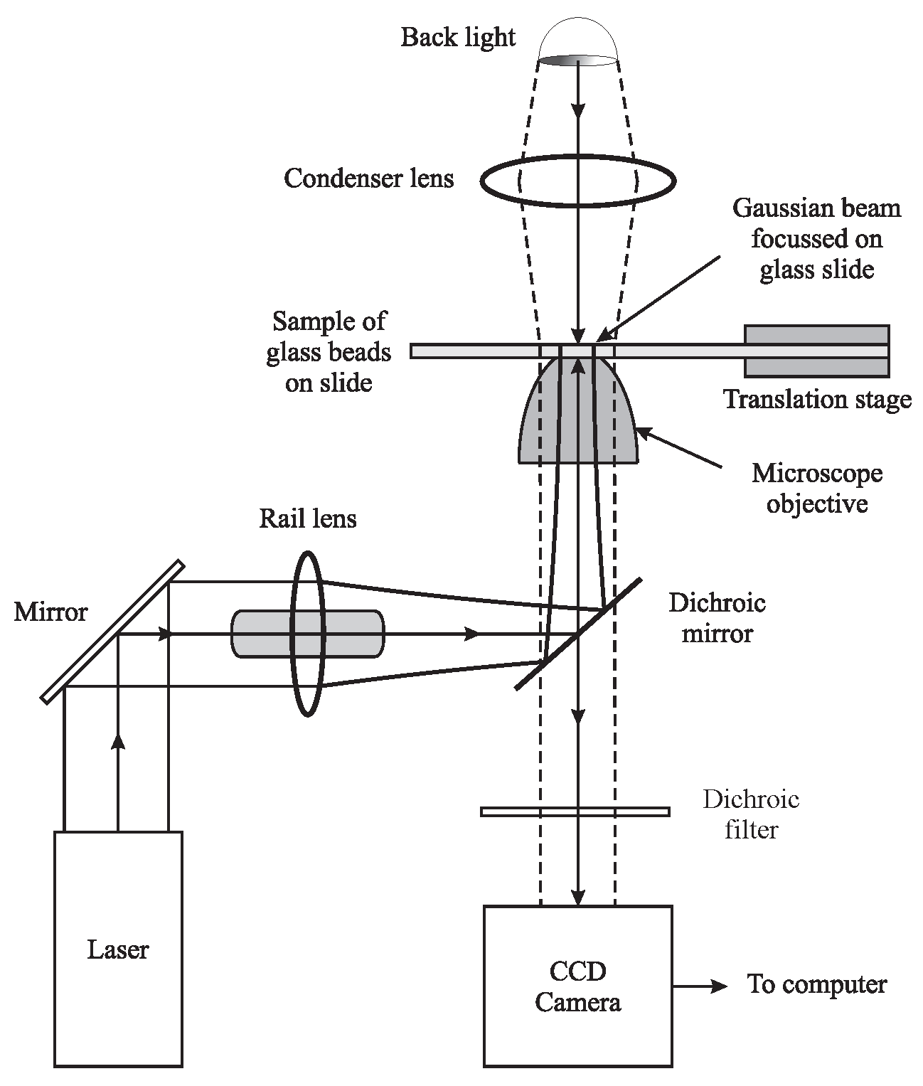
We have also introduced an optical tweezers experiment based on Reference [68]. A suspension of polystyrene beads (∼1–2 μm in diameter) in saline solution is placed in a channel on a cover slide attached to a translation stage (shown in Figure 17). The beads can be viewed on a CCD camera using a backlight for shadow imaging, as shown in Figure 18a. The beads are trapped using light from a diode laser that outputs ∼50 mW of power at a wavelength λ = 532 nm. Most of the laser light incident on a dichroic mirror (oriented at 45° as shown in Figure 17) is focused onto the sample using a microscope objective. A lens mounted on a rail is used to adjust the size of the beam at the entrance to the objective. A small fraction of the back-scattered light from a trapped bead will pass through the dichroic mirror, along the line of sight associated with the backlight. The position of the bead can be tracked using the CCD camera. A LabVIEW interface displays an image of the trapped bead obtained by subtracting background light, as shown in Figure 18b. The interface allows the data associated with the trapped bead to be displayed either in real time or after the acquisition of a number of frames. Figure 18b also displays the spatial profiles of light reflected off a trapped bead along two orthogonal directions. These plots represent pixel readouts along directions marked by cursors placed on the image of the trapped bead. Due to the relatively slow processing time of the CCD camera, the data representing the bead positions are well separated in time (∼15 ms) so that correlation effects can be ignored.
Figure 19a shows the mean-squared displacement of the bead (calculated in software) as a function of the inverse laser power. The spring constant, k s , of the harmonic potential associated with the dipole force trap is proportional to laser intensity. Therefore, the mean-squared displacement is inversely related to laser power in a manner consistent with expectations. The spring constant of the dipole force trap as a function of the laser power is shown in Figure 19b. The spring constant was calculated by using the equipartition theorem and the measured mean squared displacement. As expected, we find that the spring constant varies linearly with laser power.
The same setup can also be used to measure the autocorrelation function of a trapped bead. In this case, a position sensitive detector (PSD) with a response time of ∼100 μs is used to track the bead position. The PSD is placed at the location of the back light. To ensure a sufficient signal-to-noise ratio, an iris is placed in front of the PSD to eliminate background light. Figure 19c shows the bead displacement measured by the PSD over a time-scale of 45 ms. An autocorrelation function can be calculated from this data, as shown in Figure 19d. The correlation time τ c is inferred by fitting the data to a Lorentzian function [68]. Figure 19e shows the correlation time τ c as a function of the laser power. The inverse dependence is consistent with the prediction for τ c = γ / k s . Here, γ is the rate of collisions between the solute molecules and the trapped bead.
An even more popular variant of this experiment has been added to the course which allows students to trap micron-sized particles in free-space using the same diode laser (Figure 20a). The simplest particles to trap are resinous particles ablated from the surface of a permanent marker or saturated cotton swab. The particles are trapped near the location of the minimum beam waist. A plastic enclosure with glass slide “windows” should be used to surround the region around the trap to shield the droplets from air currents. Particles can also be introduced to the trapping beam by atomization through one of the windows. Students are able to measure the spring constant of the traps for different particles such as charcoal, graphite and carbon black ink (Figure 20b).
The lab manual provides an introduction to the origin of the optical dipole force (ODF) on glass beads and discusses the mechanism by which the ODF can trap neutral atoms. The techniques used in this experiment are widely applied in biophysics to manipulate proteins, DNA, and other organic molecules that can be tethered to glass beads [69,70]. This experiment has additional relevance to atom trapping since neutral atoms that are laser cooled and trapped in a MOT can also been loaded into an ODF trap, also known as a far off resonance trap (FORT). FORTs can be designed to have large potential well depths and have the advantage of low scattering rates in comparison to MOTs.

3.10. Atom Trapping in a MOT

The overall goals of the atom trapping course (PHYS 4062) is to provide students with hands-on expertise and experience that is similar to that of a research lab. PHYS 4062 is an elective course with an enrollment of approximately ten students. The course operates with two independent setups consisting of two groups of five students. Each student group is guided by a teaching assistant. We find that students routinely trap atoms in three to four weeks and can focus on cold atom experiments for about four weeks. After the completion of laboratory work, students are allotted three weeks to submit a formal long-form lab report that requires interpretation of data and a comprehensive discussion.
Figure 21a shows a picture of the atom trapping apparatus. The stainless steel vacuum chamber has eight symmetrically aligned viewports in the horizontal plane and two viewports along the vertical axis. Six viewports are used by the three pairs of orthogonally directed trapping beams. Two viewports in the horizontal plane are used for CCD imaging of the atom cloud (shown in Figure 21b) and detection of trap fluorescence using a photodiode. The two remaining viewports can be used for experiments such as absorption spectroscopy with a probe laser.
Typically, it takes a few weeks to prepare a vacuum system that is suitable for atom trapping. Therefore, it is preferable for students to work with a chamber that has already been pumped out. The vacuum system is initially pumped down using a turbo pump and baked at ∼100 °C for a few weeks so that the base pressure is ∼10−9 Torr at the end of the bake-out. The turbo pump is then disconnected and an ion pump with a pumping speed of 8 L per second is used to maintain the vacuum. The Rb source consists of a sealed ampoule that is fused to a glass-to-metal adapting flange. The Rb source can be fabricated in a glass shop using a commercially available ampoule and a glass-to-metal adapter. The seal can be broken in vacuum by using a magnet to manipulate a glass-enclosed magnetic striker. During the atom trapping experiments, the typical vapor pressure of Rb atoms in this chamber is ∼ 5 × 10 8 Torr.
The number of atoms that can be accumulated in a MOT can be optimized by maximizing the laser cooling force and the atom trapping force. The trapping beam diameter, which is set by the available power and laser detuning, determines the laser cooling force [71]. Typically, the atom trapping force can be maximized under conditions in which the Zeeman shift is comparable to the Doppler shift. For 85Rb atoms, this is achieved using a magnetic field gradient of ∼10 G/cm. The anti-Helmholtz coils of the MOT shown in Figure 21a (diameter ∼20 cm, ∼140 turns) can produce the required magnetic field gradient with an operating current of ∼5 A. The coils can constructed by winding magnet wire on a plastic or metal frame.
For a multi-level atom such as 85Rb exposed to a high-intensity laser beam, the laser cooling force is maximized [72] for a trap laser detuning of ∼15 MHz below the F = 3 F = 4 cycling transition (see Figure 2a). A second (repump) laser is tuned to the F = 2 F = 3 transition to optically pump atoms out of the F = 2 ground state. The recommended power in the trapping laser is >50 mW. For a trapping beam with 50 mW of power and a diameter of ∼1 cm, we find that a repump laser power of ∼1 mW is sufficient. We find that the experiments described in the next section of this paper can be carried out without the need to actively lock the repump laser due to the power available (∼50 mW) . However, the repump laser frequency is carefully monitored to ensure that it coincides with the resonant frequency. The number of trapped atoms can be maximized if the repump laser is combined with the trapping beams along all three axes using polarizing beam splitters. However, it is possible to operate the MOT even if the repump laser is aligned along a separate axis through the center of the chamber.
The trapping laser is aligned along three orthogonal directions of the trapping chamber using polarizing cube beam splitters and λ/2-plates to control the relative intensities in each direction. At the entrance to the trapping chamber, each incident beam is circularly polarized using a λ/4-wave plate and aligned through the centers of the viewports. After passing through the chamber, each beam is directed through another λ/4-wave plate and retro-reflected. This alignment ensures that the polarization of the MOT laser beams is set to a σ + σ configuration along each orthogonal direction. The incident and retro-reflected beams have opposite angular momentum with respect to the axis defined by the incident beam. Due to quantum mechanical selection rules, these beams drive atomic transitions between hyperfine states with magnetic quantum numbers that differ by Δ m F = ± 1 , provided that the quantization axis is collinear with the axis of propagation.
Maxwell’s equations ensure that the magnetic field gradients along the three orthogonal directions satisfy the condition that · B = 0 . Therefore, it is necessary to ensure that two of the incident trapping beams in the horizontal plane have the same angular momentum due to cylindrical symmetry. The third incident beam (along the vertical axis in this case) is set with the opposite angular momentum. The orientations of the first λ/4-wave plate in each of the incident beams should be set carefully to ensure circular polarization. However, the σ + σ configuration for a MOT can be achieved for any orientation of the second λ/4-wave plate.
The MOT is formed at the location where the magnetic field is zero. Therefore, it is important to align the anti-Helmholtz coils so that the field is zero at the center of the apparatus. It is also important to ensure that the laser beams are centered at this location. Ideally the Earth’s magnetic field, which shifts the position of zero field, should be canceled at the center of the chamber using three pairs of Helmholtz coils. However, cancellation of ambient fields is generally not required in an instructional experiment.
We have described the standard configuration used for a vapor cell loaded MOT [1] in which the repump laser is derived from a separate diode laser. The advantage of this approach is that the experimental setup is well suited to develop hands-on experience and promotes an interactive approach. In this arrangement, we find that students are able to make mistakes and correct them with relative ease.
Other possible configurations include a system of pyramidal mirrors that ensure the MOT is automatically aligned if the incident beams are directed along the appropriate axis [73]. It is notable that miniaturized vacuum chambers using epoxied glass sheets have been used [74]. It is also possible to introduce an EOM in the trapping laser to generate a sideband that corresponds to the repump transition frequency.
We now provide a step-wise description of the stages involved in the atom trapping experiment. A small fraction of laser light is required for setting up saturated absorption for both trap and repump lasers. The repump laser is tuned to resonance with the F = 2 F = 3 transition in 85Rb. The trap laser is locked to the peak of a crossover transition ∼60 MHz below the F = 3 F = 4 transition in 85Rb [see Figure 2c]. Most of the trap laser light is aligned through a single pass AOM operating with a frequency upshift of 45 MHz so that the laser frequency of the diffracted beam is ∼15 MHz below the F = 3 F = 4 resonance. The diffracted beam serves as the trapping laser and it can be conveniently amplitude modulated using the AOM. This beam is combined with the repump laser using a polarizing beam splitter. The combined beams are split into three paths and aligned through the vacuum chamber. Ideally, the retro-reflected beams should be aligned collinear within a few milliradians with respect to the incident beams. Spatial filtering of the beams using fibers can result in a significant increase in the number of trapped atoms. However, we avoid the use of fibers since there is a 50% reduction in laser power and increased experimental complexity. The polarization of the three orthogonal trapping laser beams can be conveniently determined throughout the beam paths by measuring the optical transmission through a rotating polarizer.
The next step involves the calibration and alignment of the anti-Helmholtz coils. The Rb source is gently heated so that the fluorescence associated with laser beams passing through the vacuum chamber is visible on a monitor or on a hand-held view scope sensitive to near-infrared light. If the frequencies of the lasers are adequately controlled and the optical alignment is satisfactory, a MOT can be observed with very few permutations to the experimental configuration. These involve switching the polarization state of the vertical trapping beams between two orthogonal circular polarizations and reversing the direction of current through the anti-Helmholtz coils.

3.11. Experiments with Laser Cooled Atoms

After optimizing the MOT, students carry out a number of straightforward experiments relating to the properties of cold atoms that are now recognized as cornerstones in the development of this field. All these experiments can be carried out by monitoring the fluorescence of the MOT using a PMT or amplified photodiode and determining the cloud radius using steady-state images captured by the CCD camera, similar to Figure 21b. Examples include tuning the lasers to trap 85Rb and 87Rb isotopes, studying the atom number as a function of the magnetic field gradient and laser frequency, measuring the atom number and atomic density using the trap fluorescence and cloud radius, determining the temperature of trapped atoms and gravitational acceleration by photographing the ballistic expansion of the trapped cloud, investigating optical pumping by turning off either the trap or repump lasers, measuring the effect of collisions from the loading rate of the trap, probe laser spectroscopy, and investigation of the spring constant of the trap. The results help students understand important properties of atom traps that were first revealed in several classic papers in the field [1,39,44,66,71,75,76,77]. We now review a selection of experiments performed by students using 85Rb atoms.
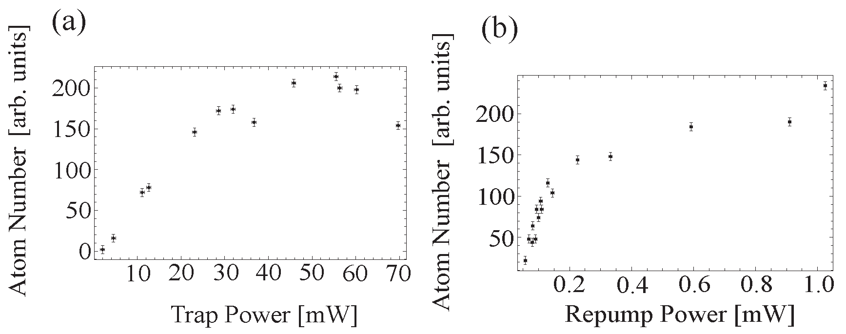
Figure 22a shows the steady state atom number, N s s , as a function of trap laser power for a fixed trap laser detuning and trapping beam diameter. The experiment is carried out with trap laser intensities that are significantly larger than the saturation intensity I sat for 85Rb atoms ( I sat = 1.67 mW/cm2 for the F = 3 , m F = 3 F = 4 , m F = 4 transition). Under these conditions, it has been predicted that the optimal detuning should be Δ = 2.5 Γ [71,72], which is the value used in this experiment. The data shows that the atom number saturates as the trap laser power is increased. This is a result of the excited state population saturating for intensities I I sat . The ratio I / I sat can be used to quantify the radiation pressure force on atoms.
To understand the steady state atom number, we note that the MOT operates by slowing and trapping atoms in the low velocity tail of the speed distribution of the background Rb vapor. The trapping beam diameter determines the maximum velocity of atoms (the capture velocity, v c ) that can be trapped. The steady state atom number is related to the capture velocity through N s s = ( d 2 / σ ) ( v c / u ) 4 [39,66], where d is the diameter of the trapping beams, σ is the cross-section for collisions with “hot” background atoms, and u is the most probable speed of the background atoms (u ∼242 m/s for 85Rb at T = 300 K).
The repump laser is combined with the trapping laser along all three orthogonal directions. Figure 22b shows N s s as a function of the repump laser power. Under these conditions, atoms can be cooled over the entire volume of Rb vapor that is illuminated by both trap and repump lasers. The data shows that the atom number saturates with an increase in repump laser power, thereby confirming that the atom number is not limited by repump laser intensity. Under these conditions, the experiment achieves complete optical pumping out of the F = 2 ground state.
For dilute traps (optical depth less than unity), photons that are absorbed and emitted by trapped atoms are not re-absorbed by other trapped atoms. Under these conditions, the density of the trap should increase as the atom number is increased [56]. As radiation trapping becomes important, the density of the cloud is expected to saturate, indicating that the cloud volume increases with an increase in atom number due to the outward pressure from re-scattered photons [75]. The data in Figure 23 is consistent with these expectations. Here, the atom number is varied by changing the trap laser power. Figure 23 also shows that the data is independent of repump laser power. The average density is calculated by combining the atom number measured from trap fluorescence and the cloud radius measured using a CCD camera. Since the trap density is relatively low, the power requirements for the repump are very modest.
It is possible to obtain atom numbers of ∼109 by using larger trapping beam diameters. Under these conditions, it is possible to observe a “bounce trap” [78] if the repump laser intensity lowered. In this situation, the repump light is highly attenuated at the center of the cloud due to absorption. Only atoms in the outer shell that are cycled on the F = 3 F = 4 transition by the trapping laser contribute to the trap fluorescence, leaving the atoms at the center of the cloud predominantly optically pumped into the F = 2 ground state. As a consequence, the trap fluorescence can scale linearly as a function of the surface area of the cloud. In contrast, if the repump laser intensity is large, the trap fluorescence can scale linearly with the cloud volume. However, to study these trends, it is important to consider a suitable method of changing the steady state atom number without independently changing the cloud size.
The capture velocity for a MOT is a non-linear function of the trapping beam diameter. As a consequence, the atom number is predicted te scale as d x , where d is the trapping beam diameter and x typically ranges from ∼3 to 4 [66,71]. The variation in x arises because the atom number must be optimized for a given trapping beam diameter by varying the detuning, trap laser intensity, and magnetic field gradient. The sensitive dependence of the atom number on the trapping beam diameter can be studied by varying the size of an aperture that is centered on the trapping beam. Figure 24a shows a strong dependence of the atom number on beam diameter. The atom number falls to zero for a finite beam diameter due to misalignment.
For small atom number, the linear variation of the density with atom number in Figure 23a suggests that radiation trapping does not affect the cloud radius for this data set. As a result, we assume that the temperature of the trapped atoms is not affected by the absorption of re-scattered photons [56]. Careful measurements of the temperature in Reference [56] suggest that the effects of radiation trapping influence the temperature even in the linear regime.
If the temperature is assumed constant, the equipartition theorem can be used to argue that the cloud radius should scale as ( d B / d z ) [56,79]. This is because k B T = k s r 2 , where k B is the Boltzmann constant and k s is the spring constant of the trap (which is directly proportional to the magnetic field gradient [72]) and r represents the cloud radius. Although it can be challenging to confirm the predicted trend, typical data shown in Figure 24b qualitatively confirms expectations that the cloud radius decreases monotonically with increasing magnetic field gradient. This is because the stiffness of the trap is proportional to the magnetic field gradient. For an optimally aligned trap, the position of the centroid of the cloud should not change when the magnetic field gradient is increased. Therefore, studies as a function of magnetic field gradient are also useful as a test of alignment.
Figure 25 shows the decay of the fluorescence from the trap after turning off the repump light reaching the trap using an AOM. The AOM has a switching time of <1 μs. The decay represents optical pumping to the F = 2 ground state. Atoms in this state do not interact with the trap laser. The data are fitted to an exponential decay to determine the optical pumping time. The value obtained from the fit is consistent with the expected time for optical pumping based on a three-level model. This data is a clear signature of optical pumping as the timescale for atoms to leave the trapping volume is much longer. This experiment also illustrates the importance of using a repump laser. An important precaution for this experiment is the time for shutting off the repump laser must be much shorter than the optical pumping time.
Figure 26a shows a measurement of the loading time of the trap obtained with a separate setup. To record this data, the magnetic field gradient was initially turned off, with the trap and repump lasers on. In this manner, the trapped atoms were allowed to escape from the trapping volume. The magnetic field gradient was then turned on and the atom number was recorded as a function of time. Alternatively, the magnetic field gradient and repump lasers can be left on, and the trap laser can be amplitude modulated. This approach makes it easier to trigger the experiment. However, it is necessary introduce a RF switch and pulse generator for amplitude modulation.
The loading rate of a vapor cell loaded MOT can be modeled by a differential equation of the form d N / d t = R Γ N [1]. Here, N is the atom number, R = n Rb d 2 v c 4 / u 3 is the capture rate of atoms from the background, n Rb is the background density of Rb atoms and Γ is the collisional rate of cold atoms with background Rb vapor. This equation assumes that there are no collisions between cold Rb atoms that can also result in a change in the atom number. The solution to this differential equation is N ( t ) = N s s ( 1 e Γ t ) , where N s s = R / Γ is the steady-state atom number. The data shown in Figure 26a is well modeled by N ( t ) . The collisional rate Γ can be extracted by fitting the data to the prediction for N ( t ) .
Loading curves such as those shown in Figure 26a can be recorded for different background Rb densities by varying the temperature of the Rb source. Since Rb has an appreciable vapor pressure at room temperature ( 3 × 10 7 Torr) and since the melting point of Rb is 312.5 K, only a small variation in the temperature of the Rb source is required to affect a significant change in the background density. Figure 26b shows that the collisional rate is a linear function of the background Rb density, n Rb . The relative density was monitored by measuring the fluorescence at the center of the cell. The measured trend is consistent with expectations, since the variation of Γ as a function of density can be described by Γ = n Rb σ v rel . Here, σ is the cross-section for collisions between background and laser cooled Rb atoms and v rel is the relative velocity between colliding atoms.
It is also an interesting exercise to monitor N s s as a function of the change in background fluorescence due to an increase in the temperature of the Rb source. For low background density, N s s increases because the increase in the capture rate R is larger than the increase in the collisional rate Γ. As the background density increases further, the trap loads faster, and N s s can be observed to decrease.
If the MOT is carefully aligned, it is possible to observe an optical molasses due to the damping force of the laser beams by turning off the magnetic field gradient. Figure 27a shows the molasses decay time for typical operating conditions. The decay is monitored by recording the fluorescence associated with cold atoms after the magnetic field gradient is turned off. The relatively fast decrease in trap fluorescence is primarily due to imbalances in the forces due to trapping beams and background magnetic fields. Typically, the molasses decay time can be extended to several seconds by improving the alignment and canceling background magnetic fields such as the Earth’s field. For these reasons, monitoring the molasses decay time can be a sensitive test of MOT alignment. This experiment was carried out by turning off the power supply driving the anti-Helmholtz coils. The time constant for turning off the current is determined primarily by the self-inductance of these coils. However, this time scale is generally much smaller than the time constant associated with molasses decay. It should be noted that in research labs, magnetic field gradients can be turned off on sub-millisecond time scales using field effect transistors (FETs) or insulated gate bipolar transistors (IGBTs).
Figure 27b shows a measurement of the temperature of the trap using the release and re-capture technique [80]. With the repump laser and magnetic field gradient on, the trap laser is pulsed off, allowing atoms to leave the central region of the MOT before the remaining atoms are recaptured by the trap light turning back on. The atom number remaining in the central region is measured by varying the “off” time of trap laser light and recording the fluorescence at the time of trap laser turn on. For this experiment, the central region is carefully imaged on an optical detector. Ideally, the repump laser and the magnetic field gradient should also be turned off. However, it is not critical to do so since these parameters have a small effect on the temperature. Turning off the magnetic field gradient and repump laser requires additional equipment. The temperature of the trapped atoms, T, is determined by fitting to an expression of the form [ R d / R ( t ) ] 3 , where R ( t ) = R 0 2 + ( u t ) 2 . Here, R d is the radius of the detection volume, R 0 is the initial cloud radius, u = 2 k B T / M is the most probable speed, and M is the atomic mass. A more complete expression for R ( t ) can be derived on the basis of References [50,53].
We note that there are several methods for measuring the temperature of the trapped atoms. For example, References [50,53] describe time of flight techniques used in References [56,79]. However, these experiments require additional lasers, changes in alignment, and synchronized timing for CCD imaging. Therefore, we find that the release and re-capture technique is generally best suited for an instructional environment.
MOTs are also well suited for several additional experiments including trapping 87Rb and spectroscopy of cold atoms. Absorption spectroscopy can be carried out by scanning the frequency of a probe laser across Rb resonances and comparing with the saturated absorption spectrum at room temperature. Alternatively, fluorescence measurements can be carried out by slowly sweeping the trap laser across resonance after the atoms have been trapped.

4. Conclusions

The development of these courses was made possible by the participation of six graduate students who validated experimental concepts, completed troubleshooting, and developed a laboratory manual [60]. This model for course development was inspired by an earlier experience in which a number of undergraduate students were able to revitalize second year laboratory courses on electromagnetism and optics with the introduction of several new experiments.
Although the impact is difficult to measure in quantitative terms, and we have not focused on measuring this impact, it is anecdotally evident that students who have completed these courses are better prepared in advanced data analysis techniques and have adequate exposure in experimental physics for graduate studies or industrial careers. Due to its relevance and potential, the introductory course on laser spectroscopy is currently a compulsory requirement for all physics streams at York University. Demand for this course has sometimes led to an expansion to two sections, each of which can accommodate 20 students. The follow up course on atom trapping has consistently experienced enrollments close to its capacity of 10 students. In all, over a thirteen year period, more than 325 students have received the specialized training offered through these courses.
The popularity of these courses seems to be related in part to the accessibility of the background material and the reliability of experiments. Students find the introductory course to be demanding, but describe the hands-on experience and the exposure to sophisticated data analysis as both new and rewarding.
The follow-up course on atom trapping seems to replicate a typical research lab environment. This course encourages students to develop data taking strategies and data interpretation skills through intense discussions. Therefore it is clear that students develop the independence and teamwork required in a research laboratory.
The most common elements of student feedback are that the experiments in both courses have nearly 100% rates of completion, with high-quality data that are well represented by fits based on underlying theoretical concepts. They have also been described as two of the most consequential courses within the physics program. These outcomes and positive student feedback in comparison with traditional laboratory courses are due in part to the nature of the experiments, emphasis on data acquisition techniques, and troubleshooting experience that are notably different from other upper-level laboratory courses.
The individual experiments described here have served as effective platforms to guide upper-level students in design concepts and research topics related to ECDLs [3,62,63], tapered amplifiers [61,65], Faraday isolators [58], electro-optic modulators [57], and analog circuits for laser frequency stabilization [55]. Other examples of developing relevant instrumentation such as Fabry-Pérot interferometers are described in Reference [81].
These courses have had an unmistakable impact on recruiting and imparting training relevant to research in ultra-cold atoms. The course has contributed to the professional development of 58 undergraduate and 14 graduate students associated with a single research group over a thirteen-year period. The quality of these students can be inferred because 80% of these graduate students and 70% of these undergraduates have been recipients of some of Canada’s most exclusive scholarships. These students have completed a variety of research projects at the undergraduate level [49,50,51,52,53,54,55,56,57,58]. Some of the contributions of graduate students are reviewed in References [64,82].
The average operational budget required to maintain these courses is approximately $3000 per year. Such an allocation is sufficient for minor equipment and for covering expenses associated with equipment failure. Typically, items that require replacement are laser diodes (costing $1000 for commercial lasers) and control electronics such as power supplies. Additionally, ion pumps (costing $1000) that are used in the atom trapping vacuum chambers may need to be replaced on a timescale of 10 years. This budget is comparable to the cost of maintaining other upper year laboratory courses.
Ideally, two trained graduate teaching assistants with a research concentration in atomic physics and one technical support staff member would be required to maintain these courses. A key requirement for sustaining these courses is the availability of suitably trained teaching assistants. We find that a small fraction of graduate students who have enrolled in the courses can be retained as teaching assistants. Over the thirteen-year period, the courses utilized nine teaching assistants of whom five have made long-term contributions.
We estimate that the cost of equipment required to set up all experiments described in this paper (based on commercially available components) is ∼$150,000. The budget is dominated by the cost of four diode laser systems (∼$80,000). The equipment budget can be substantially reduced by using home-built ECDLs and MOPAs as described in Section 2 [63,65]. As an example, the cost of four home-built ECDLs and a single MOPA system is about $26,000. Other home-built components could include Faraday isolators, locking circuits, and Rb reference cells. A list of equipment relating to individual experiments and the laboratory manual [60] are available upon request.
In conclusion, we expect that this paper will serve as a useful model for developing contemporary experiments related to laser spectroscopy and atom trapping. A few leading institutions such as California Institute of Technology, University of Michigan and Stony Brook University and several liberal arts colleges have also developed courses in related areas. Although we have described a comprehensive approach in which a range of experiments are carried out over fixed laboratory hours, alternative formats that may be equally effective could involve the introduction of even a small subset of these experiments. A laboratory course with one or two ECDLs and open hours as in the traditional format, may be well suited to expose students to the key topics.

Author Contributions

Conceptualization, H.C.B., S.W., B.B., A.V., N.A.-J., A.P., G.C. and A.K.; Data curation, H.C.B., S.W., C.M., B.B., A.V., N.A.-J., M.A., A.P., G.C., K.B.B. and R.M.; Formal analysis, H.C.B., S.W., C.M., B.B., A.V. and K.B.B.; Funding acquisition, A.K.; Investigation, H.C.B., S.W., C.M., B.B., R.B., A.V., F.Y., N.A.-J., A.P., G.C., K.B.B. and T.V.; Methodology, H.C.B., S.W., C.M., B.B., A.V., G.C. and R.M.; Project administration, A.K.; Resources, R.B., F.Y., N.A.-J., M.A., A.P., G.C. and A.K.; Software, A.V.; Supervision, C.M. and B.B.; Validation, R.B., F.Y., N.A.-J., A.P. and G.C.; Writing—original draft, H.C.B., M.A., G.C. and A.K.; Writing—review & editing, H.C.B., M.A., G.C. and A.K. H.B., S.W., C.M., and B.B. conceptualized and tested most of the experiments described here. H.B., M.A., and G.C. wrote most of the manuscript. A.V. designed the optical tweezers experiment to trap polystyrene beads in solution and H.B. designed the free-space version of this experiment. R.B. and F.Y. built atom trapping set-ups. A.V. and N.A.-J. designed and constructed home-built lasers. A.P. constructed MOPA systems. A.P. and R.M. modified the optical detectors and the heterodyne experiments. N.A.-J. and R.M. improved the Zeeman shift experiment. G.C., K.B.B., and T.V. optimized the free-space tweezers experiment. All authors have read and agree to the published version of the manuscript.

Funding

This work is supported by: the Canada Foundation for Innovation, Ontario Innovation Trust, Natural Sciences and Engineering Research Council of Canada, Ontario Centers of Excellence, and York University.

Acknowledgments

We acknowledge the role of graduate teaching assistants M. Weel, S. Beattie, I. Chan, E. Rotberg, A. Carew, and undergraduate students S. Chudasama, D. Gosset, K. Sowka, V. Popovici, H. Morrison, A. Sibilia, J. Perez Garcia, B. Barron, S. Chudasama, P. Dowling, S. Jackson, and A. Schiff-Kearn, who have helped develop different aspects of experiments. We thank C. Guimaraes for providing data in Figure 15. The courses were developed as a result of a gift of $125,000 from Optech Inc. and matching funds from the Faculty of Science and Engineering at York University. A recent $250,000 gift from Iristel Inc. is expected to contribute to renovations and upgrades.

Conflicts of Interest

The authors declare no conflict of interest.

References

  1. Monroe, C.; Swann, W.; Robinson, H.; Wieman, C. Very cold trapped atoms in a vapor cell. Phys. Rev. Lett. 1990, 65, 1571. [Google Scholar] [CrossRef] [PubMed] [Green Version]
  2. Raab, E.L.; Prentiss, M.; Cable, A.; Chu, S.; Pritchard, D.E. Trapping of neutral sodium atoms with radiation pressure. Phys. Rev. Lett. 1987, 59, 2631. [Google Scholar] [CrossRef] [Green Version]
  3. Ricci, L.; Weidemuller, M.; Esslinger, T.; Hemmerich, A.; Zimmermann, C.; Vuletic, V.; Konig, W.; Hänsch, T.W. A compact grating-stabilized diode laser system for atomic physics. Opt. Commun. 1995, 117, 541. [Google Scholar] [CrossRef] [Green Version]
  4. MacAdam, K.; Steinbach, A.; Wieman, C. A narrow-band tunable diode laser system with grating feedback, and a saturated absorption spectrometer for Cs and Rb. Am. J. Phys. 1992, 60, 1098. [Google Scholar] [CrossRef] [Green Version]
  5. Weiman, C.; Hollberg, L. Using diode lasers for atomic physics. Rev. Sci. Instrum. 1991, 62, 1. [Google Scholar] [CrossRef] [Green Version]
  6. Libbecht, K.G.; Boyd, R.A.; Williams, P.A.; Gustavson, T.L.; Kim, D.K. Teaching physics with 670 nm diode lasers—construction of stabilized lasers and lithium cells. Am. J. Phys. 1995, 63, 729. [Google Scholar] [CrossRef]
  7. Carr, A.V.; Sechrest, Y.H.; Waitukaitis, S.R.; Perreaulta, J.D.; Lonij, V.P.A.; Cronin, A.D. Cover slip external cavity diode laser. Rev. Sci. Instrum. 2007, 78, 106108. [Google Scholar] [CrossRef] [Green Version]
  8. Baillard, X.; Gauguet, A.; Bize, S.; Lemonde, P.; Laurent, P.; Clairon, A.; Rosenbusch, P. Interference-filter-stabilized external-cavity diode lasers. Opt. Commun. 2006, 266, 609. [Google Scholar] [CrossRef] [Green Version]
  9. Gilowski, M.; Schubert, C.; Zaiser, M.; Herr, W.; Wubbena, T.; Wendrich, T.; Muller, T.; Rasel, E.M.; Ertmer, W. Narrow bandwidth interference filter-stabilized diode laser systems for the manipulation of neutral atoms. Opt. Commun. 2007, 280, 443. [Google Scholar] [CrossRef] [Green Version]
  10. Phillips, W.D. Nobel Lecture: Laser cooling and trapping of neutral atoms. Rev. Mod. Phys. 1998, 70, 721. [Google Scholar] [CrossRef] [Green Version]
  11. Cohen-Tannoudji, C.N. Nobel Lecture: Manipulating atoms with photons. Rev. Mod. Phys. 1998, 70, 707. [Google Scholar] [CrossRef] [Green Version]
  12. Chu, S. Nobel Lecture: The manipulation of neutral particles. Rev. Mod. Phys. 1998, 70, 685. [Google Scholar] [CrossRef]
  13. Ketterle, W. Nobel lecture: When atoms behave as waves: Bose-Einstein condensation and the atom laser. Rev. Mod. Phys. 2002, 74, 1131. [Google Scholar] [CrossRef] [Green Version]
  14. Cornell, E.A.; Wieman, C.E. Nobel Lecture: Bose-Einstein condensation in a dilute gas, the first 70 years and some recent experiments. Rev. Mod. Phys. 2002, 74, 875. [Google Scholar] [CrossRef] [Green Version]
  15. Hänsch, T.W. Nobel lecture: Passion for precision. Rev. Mod. Phys. 2006, 78, 1297. [Google Scholar] [CrossRef] [Green Version]
  16. Hall, J.L. Nobel Lecture: Defining and measuring optical frequencies. Rev. Mod. Phys. 2006, 78, 1279. [Google Scholar] [CrossRef] [Green Version]
  17. Glauber, R.J. Nobel Lecture: One hundred years of light quanta. Rev. Mod. Phys. 2006, 78, 1267. [Google Scholar] [CrossRef] [Green Version]
  18. Haroche, S. Nobel Lecture: Controlling photons in a box and exploring the quantum to classical boundary. Rev. Mod. Phys. 2013, 85, 1083. [Google Scholar] [CrossRef] [Green Version]
  19. Wineland, D.J. Nobel Lecture: Superposition, entanglement, and raising Schrödinger’s cat. Rev. Mod. Phys. 2013, 91, 1103. [Google Scholar] [CrossRef]
  20. Ashkin, A. NobelPrize.org. Nobel Media AB. 2019. Available online: https://www.nobelprize.org/prizes/physics/2018/ashkin/lecture/ (accessed on 16 March 2019).
  21. Mourou, G. Nobel Lecture: Extreme light physics and application. Rev. Mod. Phys. 2019, 85, 1103. [Google Scholar] [CrossRef]
  22. Strickland, D. Nobel Lecture: Generating high-intensity ultrashort optical pulses. Rev. Mod. Phys. 2019, 91, 030502. [Google Scholar] [CrossRef]
  23. Peters, A.; Chung, K.; Chu, S. Measurement of gravitational acceleration by dropping atoms. Nature 1999, 400, 849. [Google Scholar] [CrossRef]
  24. Kasevich, M.; Chu, S. Atomic interferometry using stimulated Raman transitions. Phys. Rev. Lett. 1991, 67, 181. [Google Scholar] [CrossRef]
  25. McGuirk, J.M.; Foster, G.T.; Fixler, J.B.; Snadden, M.J.; Kasevich, M.A. Sensitive absolute-gravity gradiometry using atom interferometry. Phys. Rev. A 2002, 65, 033608. [Google Scholar] [CrossRef] [Green Version]
  26. Gustavson, T.L.; Bouyer, P.; Kasevich, M.A. Precision rotation measurements with an atom interferometer gyroscope. Phys. Rev. Lett. 1997, 78, 2046. [Google Scholar] [CrossRef] [Green Version]
  27. Kohel, N.Y.J.M.; Kellogg, J.R.; Maleki, L. Development of an atom-interferometer gravity gradiometer for gravity measurement from space. Appl. Phys. B 2006, 84, 647. [Google Scholar]
  28. Gouet, J.L.; Mehlstaubler, T.E.; Kim, J.; Merlet, S.; Clairon, A.; Landragin, A.; Santos, F.P.D. Limits to the sensitivity of a low noise compact atomic gravimeter. Appl. Phys. B 2008, 92, 133. [Google Scholar] [CrossRef] [Green Version]
  29. Young, B.; Bonomi, D.S.; Patterson, T.; Roller, F.; Tran, T.; Vitouchkine, A.; Gustavson, T.; Kasevich, M. Atom Optic Inertial and Gravitational Sensors; Laser Science XXIII, OSA Technical Digest, Paper LTuH1; Optical Society of America: California, CA, USA, 2007. [Google Scholar]
  30. Weiss, D.; Young, B.; Chu, S. Precision measurement of the photon recoil of an atom using atomic interferometry. Phys. Rev. Lett. 1993, 70, 2706. [Google Scholar] [CrossRef] [PubMed]
  31. Wicht, A.; Hensley, J.M.; Sarajlic, E.; Chu, S. A preliminary measurement of the fine structure constant based on atom interferometry. Phys. Scr. 2002, T102, 82. [Google Scholar] [CrossRef]
  32. Cladé, P.; de Mirandes, E.; Cadoret, M.; Guellati-Khxexlifa, S.; Schwob, C.; Nez, F.; Julien, L.; Biraben, F. Determination of the fine structure constant based on Bloch oscillations of ultracold atoms in a vertical optical lattice. Phys. Rev. Lett. 2006, 96, 033001. [Google Scholar] [CrossRef] [Green Version]
  33. Cadoret, M.; de Mirandes, E.; Cladé, P.; Guellati-Khxexlifa, S.; Schwob, C.; Nez, F.; Julien, L.; Biraben, F. Combination of Bloch oscillations with a Ramsey-Bordé interferometer: new determination of the fine structure constant. Phys. Rev. Lett. 2008, 101, 230801. [Google Scholar] [CrossRef] [PubMed] [Green Version]
  34. Fray, S.; Diez, C.A.; Hänsch, T.W.; Weitz, M. Atomic interferometer with amplitude gratings of light and its applications to atom based tests of the equivalence principle. Phys. Rev. Lett. 2004, 93, 240404. [Google Scholar] [CrossRef] [PubMed] [Green Version]
  35. Müller, H.; Peters, A.; Chu, S. A precision measurement of the gravitational redshift by the interference of matter waves. Nature 2010, 463, 926. [Google Scholar] [CrossRef] [PubMed]
  36. Chou, C.; Hume, D.; Rosenband, T.; Wineland, D. Optical clocks and relativity. Science 2010, 329, 1630. [Google Scholar] [CrossRef] [Green Version]
  37. Wood, C.S.; Bennett, S.C.; Cho, D.; Masterson, B.P.; Roberts, J.L.; Tanner, C.E.; Wieman, C.E. Measurement of parity nonconservation and an anapole moment in cesium. Science 1997, 275, 1759. [Google Scholar] [CrossRef] [Green Version]
  38. Santarelli, G.; Laurent, P.; Lemonde, P.; Clairon, A.; Mann, A.G.; Chang, S.; Luiten, A.N.; Salomon, C. Quantum projection noise in an atomic fountain: A high stability cesium frequency standard. Phys. Rev. Lett. 1999, 82, 4619. [Google Scholar] [CrossRef] [Green Version]
  39. Gibble, K.; Chu, S. Laser-cooled Cs frequency standard and a measurement of the frequency shift due to ultracold collisions. Phys. Rev. Lett. 1993, 70, 1771. [Google Scholar] [CrossRef]
  40. Udem, T.; Reichert, J.; Holzwarth, R.; Hänsch, T.W. Absolute Optical Frequency Measurement of the Cesium Line with a Mode-Locked Laser. Phys. Rev. Lett. 1999, 82, 3568. [Google Scholar] [CrossRef] [Green Version]
  41. Udem, T.; Huber, A.; Gross, B.; Reichert, J.; Prevedelli, M.; Weitz, M.; Hänsch, T.W. Phase-Coherent Measurement of the Hydrogen 1S-2S Transition Frequency with an Optical Frequency Interval Divider Chain. Phys. Rev. Lett. 1997, 79, 2646. [Google Scholar] [CrossRef]
  42. Anderson, M.H.; Ensher, J.R.; Matthews, M.R.; Wieman, C.E.; Cornell, E.A. Observation of Bose-Einstein condensation in a dilute atomic vapor. Science 1995, 269, 198. [Google Scholar] [CrossRef] [Green Version]
  43. Davis, K.B.; Mewes, M.O.; Andrews, M.R.; van Druten, N.J.; Durfee, D.S.; Kurn, D.M.; Ketterle, W. Bose-Einstein condensation in a gas of sodium atoms. Phys. Rev. Lett. 1995, 75, 3969. [Google Scholar] [CrossRef] [PubMed] [Green Version]
  44. Ovchinnikov, Y.B.; Müller, J.H.; Doery, M.R.; Vredenbregt, E.J.D.; Helmerson, K.; Rolston, S.L.; Phillips, W.D. Diffraction of a released Bose-Einstein condensate by a pulsed standing light wave. Phys. Rev. Lett. 1999, 83, 284. [Google Scholar] [CrossRef] [Green Version]
  45. Andrews, M.R.; Townsend, C.G.; Miesner, H.-J.; Durfee, D.S.; Kurn, D.M.; Ketterle, W. Observation of Interference Between Two Bose Condensates. Science 1997, 31, 275637. [Google Scholar] [CrossRef] [PubMed] [Green Version]
  46. Schneble, D.; Torii, Y.; Boyd, M.; Streed, E.W.; Pritchard, D.E.; Ketterle, W. The onset of matter-wave amplification in a superradiant Bose-Einstein condensate. Science 2003, 300, 475. [Google Scholar] [CrossRef] [PubMed] [Green Version]
  47. Greiner, M.; Mandel, O.; Esslinger, T.; Hänsch, T.; Bloch, I. Quantum phase transition from a superfluid to a Mott insulator in a gas of ultracold atoms. Nature 2002, 415, 39. [Google Scholar] [CrossRef]
  48. Zoest, T.V.; Gaaloul, N.; Singh, Y.; Ahlers, H.; Herr, W.; Seidel, S.T.; Ertmer, W.; Rasel, E.; Eckart, M.; Kajari, E.; et al. Bose-Einstein condensation in microgravity. Science 2010, 328, 1540. [Google Scholar] [CrossRef] [Green Version]
  49. Weel, M.; Kumarakrishnan, A. Laser-frequency stabilization using a lock-in amplifier. Can. J. Phys. 2002, 80, 1449. [Google Scholar] [CrossRef]
  50. Yavin, I.; Weel, M.; Andreyuk, A.; Kumarakrishnan, A. A calculation of the time-of-flight distribution of trapped atoms. Am. J. Phys. 2002, 70, 149. [Google Scholar] [CrossRef] [Green Version]
  51. Spirou, G.; Yavin, I.; Weel, M.; Vorozcovs, A.; Kumarakrishnan, A.; Battle, P.R.; Swanson, R.C. A high-speed-modulated retro-reflector for lasers using an acousto-optic modulator. Can. J. Phys. 2003, 81, 625. [Google Scholar] [CrossRef]
  52. Mikaelian, T.; Weel, M.; Kumarakrishnan, A.; Battle, P.R.; Swanson, R.C. A high-speed retro-reflector for free-space communication based on electro-optic phase modulation. Can. J. Phys. 2003, 81, 639. [Google Scholar] [CrossRef]
  53. Yavin, I.; Mikaelian, T.; Kumarakrishnan, A. Calculation of the transfer efficiency between dual magneto-optical traps and simulation of a Ioffe trap for Bose Einstein condensation. Can. J. Phys. 2003, 81, 651. [Google Scholar] [CrossRef]
  54. Cauchi, S.; Vorozcovs, A.; Weel, M.; Beattie, S.; Gagnon, O.; Kumarakrishnan, A. Absorption spectroscopy of trapped rubidium atoms. Can. J. Phys. 2004, 82, 905. [Google Scholar] [CrossRef]
  55. Sowka, K.; Weel, M.; Cauchi, S.; Cockins, L.; Kumarakrishnan, A. Laser-frequency stabilization using a lock-in amplifier. Can. J. Phys. 2005, 83, 907. [Google Scholar] [CrossRef]
  56. Vorozcovs, A.; Weel, M.; Beattie, S.; Cauchi, S.; Kumarakrishnan, A. Measurements of temperature scaling laws in an optically dense magneto-optical trap. J. Opt. Soc. Am. B 2005, 22, 943. [Google Scholar] [CrossRef] [Green Version]
  57. Mok, C.; Weel, M.; Rotberg, E.; Kumarakrishnan, A. Design and construction of an efficient electro-optic modulator for laser spectroscopy. Can. J. Phys. 2006, 84, 775. [Google Scholar] [CrossRef] [Green Version]
  58. Winter, S.; Mok, C.; Kumarakrishnan, A. Tools for laser spectroscopy: The design and construction of a Faraday isolator. Can. J. Phys. 2006, 84, 845. [Google Scholar] [CrossRef]
  59. Wolfram, S. wolfram.com 2020. Available online: https://reference.wolfram.com/language/guide/HelpMenu.html (accessed on 25 April 2020).
  60. Barrett, B.; Carew, A.; Beica, H.C.; Carlse, G.; Kumarakrishnan, A. (Eds.) Laboratory Manual for PHYS 4061 and PHYS 4062; York University: Toronto, ON, Canada, 2018. [Google Scholar]
  61. Nyman, R.A.; Varoquaux, G.; Villier, B.; Sacchet, D.; Moron, F.; Coq, Y.L.; Aspect, A.; Bouyer, P. Tapered-amplified antireflection-coated laser diodes for potassium and rubidium atomic-physics experiments. Rev. Sci. Instrum. 2006, 77, 033105. [Google Scholar] [CrossRef] [Green Version]
  62. Beica, H.C.; Carew, A.; Vorozcovs, A.; Dowling, P.; Pouliot, A.; Barron, B.; Kumarakrishnan, Ȧ. Characterization and applications of auto-locked vacuum-sealed diode lasers for precision metrology. Proc. SPIE 2017, 101910K, 6. [Google Scholar]
  63. Beica, H.C.; Pouliot, A.; Carew, A.; Vorozcovs, A.; Afkhami-Jeddi, N.; Vacheresse, T.; Carlse, G.; Dowling, P.; Barron, B.; Kumarakrishnan, A. Characterization and applications of auto-locked vacuum-sealed diode lasers for precision metrology. Rev. Sci. Instrum. 2019, 90, 085113. [Google Scholar] [CrossRef]
  64. Barrett, B.; Carew, A.; Beica, H.C.; Vorozcovs, A.; Pouliot, A.; Kumarakrishnan, A. Prospects for precise measurements with echo atom interferometry. Atoms 2016, 4, 19. [Google Scholar] [CrossRef] [Green Version]
  65. Pouliot, A.; Beica, H.C.; Carew, A.; Vorozcovs, A.; Carlse, G.; Kumarakrishnan, A. Auto-locking waveguide amplifier system for lidar and magnetometric applications. Proc. SPIE 2018, 10514, 105140S. [Google Scholar]
  66. Gibble, K.E.; Kasapi, S.; Chu, S. Improved magneto-optic trapping in a vapor cell. Opt. Lett. 1992, 17, 526. [Google Scholar] [CrossRef] [PubMed]
  67. Dinneen, T.; Wallace, C.; Gould, P. Narrow linewidth, highly stable, tunable diode laser system. Opt. Commun. 1992, 92, 277. [Google Scholar] [CrossRef]
  68. Bechhoefer, J.; Wilson, S. Faster, cheaper, safer optical tweezers for the undergraduate laboratory. Am. J. Phys. 2002, 70, 393. [Google Scholar] [CrossRef]
  69. Perkins, T.; Smith, D.E.; Chu, S. Direct observation of tube-like motion of a single polymer chain. Science 1994, 64, 819. [Google Scholar] [CrossRef] [Green Version]
  70. Henon, S.; Lenormand, G.; Richert, A.; Gallet, F. A new determination of the shear modulus of the human erythrocyte membrane using optical tweezers. Biophys. J. 1999, 76, 1145. [Google Scholar] [CrossRef] [Green Version]
  71. Lindquist, K.; Stephens, M.; Wieman, C. Experimental and theoretical study of the vapor-cell Zeeman optical trap. Phys. Rev. A 1992, 46, 4082. [Google Scholar] [CrossRef]
  72. Metcalf, H.J.; Straten, P.V. Laser Cooling and Trapping; Springer: New York, NY, USA, 1999. [Google Scholar]
  73. Mellish, A.S.; Wilson, A.C. A simple laser cooling and trapping apparatus for undergraduate laboratories. Am. J. Phys. 2002, 70, 965. [Google Scholar] [CrossRef]
  74. Wieman, C.; Flowers, G.; Gilbert, S. Inexpensive laser cooling and trapping experiment for undergraduate laboratories. Am. J. Phys. 1995, 63, 317. [Google Scholar] [CrossRef]
  75. Walker, T.; Sesko, D.; Wieman, C. Collective behavior of optically trapped neutral atoms. Phys. Rev. Lett. 1990, 64, 408. [Google Scholar] [CrossRef] [Green Version]
  76. Lett, P.D.; Phillips, W.D.; Rolston, S.L.; Tanner, C.E.; Watts, R.N.; Westbrook, C.I. Optical molasses. J. Opt. Soc. Am. B 1989, 6, 2084. [Google Scholar] [CrossRef] [Green Version]
  77. Chu, S.; Wieman, C. Atom cooling, trapping, and quantum manipulation. Laser Cooling and Trapping. J. Opt. Soc. Am. B 1989, 60, 2020. [Google Scholar]
  78. Ketterle, W.; Davis, K.B.; Joffe, M.A.; Martin, A.; Pritchard, D.E. High densities of cold atoms in a dark spontaneous-force optical trap. Phys. Rev. Lett. 1993, 70, 2253. [Google Scholar] [CrossRef] [PubMed]
  79. Wallace, C.D.; Dinneen, T.P.; Tan, K.Y.N.; Kumarakrishnan, A.; Gould, P.L.; Javanainen, J. Measurements of temperature and spring constant in a magneto-optical trap. J. Opt. Soc. Am. B 1994, 11, 703. [Google Scholar] [CrossRef]
  80. Chu, S.; Hollberg, L.; Bjorkholm, J.E.; Cable, A.; Ashkin, A. Three-dimensional viscous confinement and cooling of atoms by resonance radiation pressure. Phys. Rev. Lett. 1985, 55, 48. [Google Scholar] [CrossRef] [Green Version]
  81. Grove, T.T. A low-cost scanning Fabry–Perot cavity for laser experiments. Am. J. Phys. 2003, 71, 184. [Google Scholar] [CrossRef]
  82. Barrett, B.; Chan, I.; Mok, C.; Carew, A.; Yavin, I.; Kumarakrishnan, A.; Cahn, S.B.; Sleator, T. Advances in Atomic, Molecular and Optical Physics; Berman, P.R., Arimondo, E., Lin, C.C., Eds.; Elsevier: New York, NY, USA, 2011; Volume 60, Chapter 3. [Google Scholar]
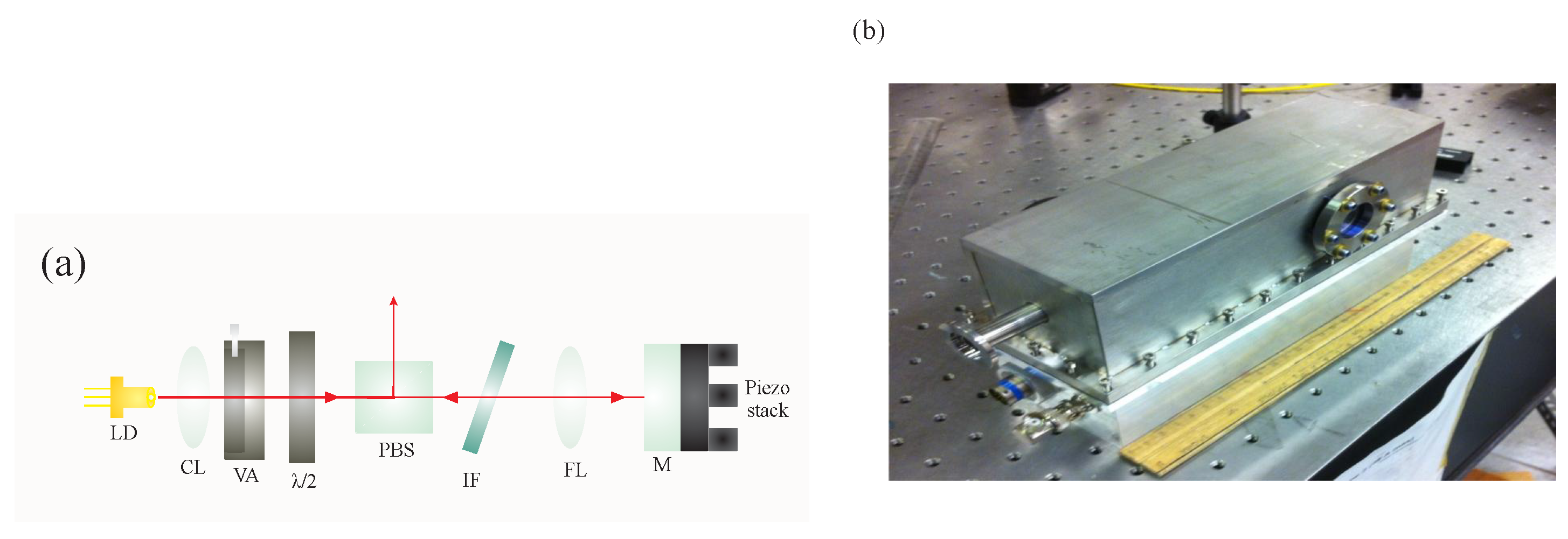
Figure 1. (a) Layout of IF laser. The optical elements are: LD—laser diode, CL—collimating lens, VA—variable aperture, λ/2—half wave-plate, PBS—polarizing beam splitter, IF—interference filter, FL—focusing lens, M—mirror. (b) Home-built IF-laser head.
Atoms 08 00025 g001
Figure 2. (a) Energy level diagrams for 85Rb and 87Rb. The Rb reference cell contains the two naturally occurring isotopes in the number ratio of 72:28. (b) Oscilloscope trace of Doppler broadened absorption spectra in 85Rb and 87Rb observed by scanning the external cavity diode laser (ECDL). The ground states corresponding to each peak are labeled. The frequency interval between the two ground states in 85Rb is marked. The time axis can be converted to frequency units based on the known separation between energy levels. The full width at half maximum (FWHM) extracted from a Gaussian fit of the F = 3 F = 2 , 3 , 4 resonance is 735 ± 5 MHz. Based on Beer’s law, I = I 0 e α ( ν ) l where α ( ν ) is the absorption coefficient, l is the length of the Rb cell, I 0 is the incident intensity and I is the transmitted intensity. We find that the maximum absorption corresponds to an optical depth of α 0 l = 0.516 ± 0.003 , where α 0 = α ( ν 0 ) and ν 0 is the resonance frequency. (c) Oscilloscope trace of Doppler-free spectrum for the 85Rb F = 3 F = 2 , 3 , 4 transitions. The frequency interval between the F = 4 peak and the adjacent crossover resonance is 60.4 MHz. (d) An expanded plot of the F = 3 F = 4 resonance line. A FWHM of 12.7 ± 0.9 MHz is obtained from a Lorentzian fit. In general, this value should have contributions from the natural broadening (∼6 MHz), power broadening, and laser linewidth.
Atoms 08 00025 g002
Figure 3. Saturated absorption setup used in emission and absorption spectroscopy, Zeeman shift, and laser frequency stabilization experiments. A quarter-wave plate represented by λ/4 is used to produce circularly polarized laser beams. A half-wave plate, represented by λ/2, is used to control the ratio of power reflected and transmitted by the polarizing beam splitter. “A” and “B” represent photodiodes used for recording absorption spectra. The absorption of a weak probe beam that serves as a reference is recorded by photodiode A. The absorption of a weak probe beam in the presence of a strong counter-propagating pump beam is recorded by photodiode B. Electronic subtraction of the signals from these photodiodes gives a Doppler-free spectrum shown in Figure 2c. Photodiode C is used to record right-angle fluorescence. Locations of the electro-optic phase modulator (EOM) used in the emission and absorption spectroscopy experiment and the solenoid used in the Zeeman shift experiment are shown by dashed lines. In experiments with the EOM, the two weak probe beams are blocked and only the pump beam remains on.
Atoms 08 00025 g003
Figure 4. Fluorescence spectra from a pump laser beam passing through an EOM and a Rb vapor cell. The laser is scanned over several GHz and a fluorescence signal is recorded by photodiode C in Figure 3. The black curve shows the fluorescence with the EOM off. The grey curve is obtained with the EOM on. The operating frequency of the EOM is 2.915 GHz which represents the energy difference between the F = 3 F = 4 and F = 2 F = 3 transitions in 85Rb.
Atoms 08 00025 g004
Figure 5. The frequency shift of the F = 3 F = 4 transition as a function of magnetic field. The frequency shift is obtained by recording the position of the spectral line in a Rb cell placed in a magnetic field relative to the position of the spectral line without a magnetic field. A value of 1.49 ± 0.08 MHz/G for the Zeeman shift is found from the slope of a straight line fit. The expected value for the Zeeman shift of the m F = 3 m F = 4 sublevel transition is 1.4 MHz/G. The horizontal error bars are estimated to be ±5% and the vertical error bars are comparable to the size of the points.
Atoms 08 00025 g005
Figure 6. Experimental setup for measurement of the laser linewidth using a FPI. The grating in the ECDL cavity is bypassed by inserting a mirror attached to a removable mount so that the linewidth of the free running laser diode can be determined. This configuration is shown by the dotted box. When the mirror is removed, the linewidth of the laser is much smaller (∼1 MHz) due to the presence of grating feedback. Since the FPI resolution is ∼60 MHz, only the instrument limited linewidth is measured in this case.
Atoms 08 00025 g006
Figure 7. Transmission peaks obtained by operating the diode laser at a fixed frequency and scanning the Fabry-Pérot interferometer (FPI). (a) FPI peaks without grating feedback. The measured FWHM is 133 ± 5 MHz. (b) FPI peaks with grating feedback. The measured FWHM of 67 ± 3 MHz is comparable to the calculated resolution of the FPI. The value of the free spectral range of the spherical mirror FPI (c/4L), calculated on the basis of the known cavity length of L = 7.5 cm is ∼1 GHz. Since the separation between adjacent transmission peaks is equal to the free spectral range, it is possible to convert the time axis into frequency units.
Atoms 08 00025 g007
Figure 8. Setup for laser frequency stabilization using a lock-in amplifier. The modulation was provided by a function generator operating at ∼7 kHz. A scan controller is used to scan the laser frequency at a rate of ∼10 Hz. An example of the saturated absorption setup is shown in Figure 3. A trace of the saturated absorption signal obtained by scanning the laser over a single Doppler-free transition is shown. For illustrative purposes, this trace was recorded with a large amplitude for frequency modulation. The output of the lock-in amplifier generates the corresponding dispersion shaped error signal. To lock the laser to the peak of this resonance line, the laser frequency is centered on the resonance peak, and the scan amplitude is gradually reduced (ideally to zero) before engaging the feedback loop.
Atoms 08 00025 g008
Figure 9. Schematic diagram showing the essential components of a lock-in amplifier.
Atoms 08 00025 g009
Figure 10. Lock-in output (error signal) obtained by scanning the laser across a resonance line for various phase shifts between the absorption signal and the modulation: (a) ϕ = 0°, (b) ϕ = 90° and (c) ϕ = 180°.
Atoms 08 00025 g010
Figure 11. Lock-in error signal recorded with and without engaging the feedback loop. For both parts of the trace, the scan amplitude has been turned off, whereas the modulation remains on. The amplitude variations are mainly due to laser frequency fluctuations, which are greatly reduced with the feedback loop engaged (lock on). Under typical operating conditions, the diode laser remains locked for about 30 min.
Atoms 08 00025 g011
Figure 12. (a) Heterodyne detection setup. The incoming beam is generated by an ECDL operating at 780 nm. The optical local oscillator (LO) is the undiffracted beam from the acousto-optic modulator (AOM). Light from one of the ECDL-based experiments described previously is aligned through th. The first order diffracted beam from the AOM is rendered co-propagating with the LO using a beam splitter and mirrors so that a heterodyne beat signal can be detected by the photodiode. The RF input to the AOM is either CW or pulsed, and the control electronics are shown. The output of the TTL switch is an RF pulse that drives the AOM. (b) The square pulse used to amplitude-modulate the AOM and corresponding time-delayed optical pulse detected by the photodiode. The square pulse is the signal input to the electronic TTL switch, which also triggers the oscilloscope. The optical pulse exhibits a beat note at the AOM drive frequency. The time delay between the onset of the square pulse and the beginning of the optical pulse is 3.45 ± 0.05 μs. This delay is consistent with the estimated time for an acoustic wave to propagate from the transducer at the edge of the AOM crystal to the location of the laser beam passing through the AOM.
Atoms 08 00025 g012
Figure 13. A charged coupled device (CCD) camera and frame grabber are used to measure the fluorescence of an electron beam as it sweeps across the screen of an analog oscilloscope. A pulse generator is used to generate a TTL pulse that controls the shutter of the CCD camera.
Atoms 08 00025 g013
Figure 14. Intensity of fluorescence due to an electron beam sweeping across the screen of a line triggered oscilloscope recorded by a shutter-controlled CCD camera. The dips in intensity correspond to the grid lines on the oscilloscope. The spacing between the grid lines is determined by the time base setting of the oscilloscope, thereby allowing the pixel axis to be converted to a time scale. The solid curve is the best fit to the data based on a decaying exponential. The fit gives a decay time of 1.30 ± 0.03 ms.
Atoms 08 00025 g014
Figure 15. (a) Beam radius, w, orthogonal to the direction of propagation as a function of distance (z) from a 20 cm focal length plano-convex lens. The beam size was measured using a scanning knife edge beam profiler. The position z = 0 represents the focal spot. The solid line is a fit to the equation w = w 0 [ 1 + ( z z 1 ) 2 / z 0 2 ] 1 / 2 , where z 0 = π w 0 2 / λ . Here, w 0 is the minimum beam radius, z 0 is the Rayleigh range and z 1 is an offset that specifies the location of the minimum beam radius from the origin. The fit gives w 0 = ( 58.7 ± 1.3 ) μm, z 0 = ( 5.8 ± 0.2 ) cm, and z 1 = ( 4.6 ± 0.8 ) mm. (b) Spatial profile of a laser beam before (black) and after (grey) passing through an optical fiber. The profile at the entrance to the fiber was obtained by distorting the beam using a scratched cover slide. The profiles represent the analog outputs of a scanning knife edge spatial profiler.
Atoms 08 00025 g015
Figure 16. Vacuum system used in the experiment. In the first stage of the experiment, valves B and C are closed and the chamber is pumped directly using the roughing pump. In the second stage, valve A is closed and the chamber is pumped by the turbo pump in series with the roughing pump.
Atoms 08 00025 g016
Figure 17. Schematic diagram of the optical tweezers experiment. The laser source is a diode laser operating at λ = 532 nm. The dichroic mirror ensures that most of the laser light reaches the microscope objective. The rail lens is used to vary the size of the laser beam. The objective focuses the laser beam to a spot size of ∼3 μm. The sample of polystyrene glass beads in saline solution is placed at the focal spot of the laser. The sample is uniformly illuminated by a backlight. Light from this lamp source passes through a condenser lens and the sample. After passing through the microscope objective, it is imaged on a CCD camera. With the laser blocked, the CCD camera can image the glass beads suspended in solution. When the optical dipole force trap is aligned, the dichroic mirror and dichroic filter ensure that a small fraction of the light scattered by the trapped beads reaches the CCD camera. The scattered light follows the same optical beam path as the backlight and is sufficiently intense for the trapped bead to be imaged.
Atoms 08 00025 g017
Figure 18. (Color online) Display of the LabVIEW interface used to record and analyze CCD images of the trapped beads. (a) Image of beads suspended in solution. (b) The upper frame shows the image of a 2 μm diameter trapped bead. The corresponding intensity profile is displayed in the lower frame.
Atoms 08 00025 g018
Figure 19. (a) Mean squared displacement as a function of inverse laser power. The power represents the measured value at the entrance to the microscope objective. Only ∼50% of the light reaches the sample. (b) Spring constant of the dipole force trap as a function of laser power. The horizontal axis has not been corrected for the power loss at the microscope objective. The points representing the spring constant are calculated from the data in (a) on the basis of the equipartition theorem. (c) Signal from the position sensitive detector (PSD), which represents the position of the bead as a function of time. (d) Autocorrelation function (black) calculated from the PSD signal by fitting to a Lorentzian (grey) for a small section of the data such as in figure (c). The horizontal axis represents the time lag between the data points in the record. The fit gives a correlation time τ c = 0.422 ± 0.005 ms. (e) Correlation time as a function of laser power.
Atoms 08 00025 g019
Figure 20. (a) Modified experimental set-up for free-space trapping experiment. (b) Spring constant of the trap as a function of laser power for a charcoal particle confined in free-space. The horizontal axis has been corrected for the power loss of the microscope objective.
Atoms 08 00025 g020
Figure 21. (a) A portion of the atom trapping setup. A pair of anti-Helmholtz coils is used to apply a magnetic field gradient. Two pairs of the trapping beams are aligned in the horizontal plane between the anti-Helmholtz coils. An orthogonal trapping beam is aligned along the vertical. (b) Image of trapped 85Rb atoms recorded by a CCD camera. An optimized trap has a 1/ e 2 cloud radius of ∼1 mm and holds ∼107 atoms. The CCD image of the trap in (b) is saturated causing blooming.
Atoms 08 00025 g021
Figure 22. (a) Steady state atom number as a function of trap laser power. The atom number is inferred by recording the trap fluorescence on a photodiode. The voltage recorded by the detector can be converted into atom number. The maximum voltage corresponds to an atom number of ∼107. Since the trap laser is retro-reflected through the vacuum chamber, the laser power incident on the atoms is approximately twice the trap laser power. (b) Atom number as a function of repump laser power. For both of these experiments, the trap laser detuning was fixed at 15 MHz below resonance, the trapping beam diameter was ∼0.90 cm and the magnetic field gradient was ∼7 G/cm.
Atoms 08 00025 g022
Figure 23. (Color online) (a) Variation in average density as a function of atom number. The atom number, inferred from trap fluorescence, was varied by changing the trap laser power. The trap laser detuning was fixed at 15 MHz below resonance, the trapping beam diameter was ∼0.90 cm and the magnetic field gradient was ∼7 G/cm. Three different repump laser powers were used, 0.60 ± 0.06 mW (red squares), 1.0 ± 0.1 mW (green circles), and 50 ± 5 mW (blue triangles). The cloud radius was determined from fits along two dimensions that were summed in quadrature. (b) Spatial profile of the cloud obtained from a CCD camera image for a trap laser power of 75 ± 7 mW, repump laser power of 50 ± 5 mW, and a magnetic field gradient of ∼7 G/cm. The vertical axis represents the intensity obtained by integrating pixel values. A Gaussian fit gives a 1 / e 2 cloud radius of 0.66 ± 0.01 mm.
Atoms 08 00025 g023
Figure 24. (a) Atom number as a function of iris diameter, d. The data shows a sensitive dependence on the beam size. For a well aligned trap and a well centered iris, the atom number can be expected exhibit a power law dependence shown by the solid line. For this experiment, the trap detuning was set to 15 MHz below resonance, the trap laser power was ∼65 mW, the repump laser power was set at ∼15 mW, and the magnetic field gradient was ∼7 G/cm. (b) Cloud radius (1/e) as a function of magnetic field gradient along the vertical direction. For this data, the trap laser power was fixed at ∼75 mW and the trap laser detuning was ∼15 MHz below resonance with a beam diameter of ∼1.0 cm. The repump power was ∼12 mW.
Atoms 08 00025 g024
Figure 25. Fluorescence from the F = 4 F = 3 transition as a function of time after blocking the repump laser. An exponential fit gives a time constant for the decay of 42.42 ± 0.05 μs. The trap laser power was 75 ± 7 mW, the repump power was 50 ± 5 mW, and the magnetic field gradient was ∼7 G/cm.
Atoms 08 00025 g025
Figure 26. (a) Loading curve for the magneto-optical trap (MOT). The data was recorded for a fixed n Rb . A fit to the functional form described in text gives Γ 1 = 1.17 ± 0.03 s. (b) Variation of the collisional rate with background fluorescence, which is proportional to n Rb .
Atoms 08 00025 g026
Figure 27. (a) Measurement of the optical molasses decay time. A fit to a decaying exponential gives a 1 / e time constant of 0.165 ± 0.002 s. (b) Measurement of the temperature of trapped atoms using the release and re-capture method. The vertical axis represents the fraction of re-captured atoms. The horizontal axis is the free expansion time. A determination of the most probable speed u from the fit gives a temperature T = 420 ± 20 μK.
Atoms 08 00025 g027