1. Introduction
The ability of a robot to move is fundamental for permitting the robot to explore its environment, interact with its surroundings, and ultimately perform useful tasks. Autonomous robotic systems are limited by the robot’s ability to move, often in challenging environments or unknown environments. These challenges increase significantly once robots are taken outside the laboratory and placed in the real world.
A robot is likely required to be able to manage a range of terrains. The ability to be able to act autonomously in a uncontrolled environment increases the difficultly. Many platforms are designed to function on a specific terrain type (e.g., indoor research laboratory, flat grass, or dry rocky areas). However, an important aspect of ensuring flexibility for a platform across a range of environments and surfaces is to permit adaptation of the robot to the surface it is operating on. Hybrid robots allow different interactions with the ground; for instance, the Cylindabot, proposed in this paper, can both roll smoothly using a form of wheel and walk with legs that can extend from these wheels.
The Wheg design allows a wheel to transform from a round wheel to a three legged structure. The term Wheg refers to a combination of wheel and leg design which is continually rotated. The benefits of this style are inspired by [
1]. This might be considered as simply a wheel of spokes without a rim. In [
2], a six spoked wheel is analysed against its performance to move up a step, and an approach/surmount theory is developed. This theory is applied to the results in this paper. The term Wheg is used in this paper to emphasise continuous rolling and discrete strides.
The Cylindabot robot is designed to allow a high degree of mobility with a minimal number of actuators. The high degree of mobility means that it can traverse smooth and jagged deviations in potential terrain in an unknown environment. The minimal actuation means that the robot is lightweight and is easier to control efficiently. The level of deployment of the the legs and tail can be locked to investigate how the capabilities change.
In this paper, the Cylindabot design is presented, experimental results illustrating the robot’s capabilities are compared to the theory developed for the design, and the results are considered against similar platforms in the literature. First, the design of the Cylindabot is discussed with an emphasis on inspiration and practical decisions made. The theory of linear bounds from [
2] is then clarified. The simulation setup and results are then summarised, followed by paired results from physical experiments. Finally, the Cylindabot is compared with the current state-of-the-art hybrid locomotion platforms.
Contributions of the Paper
A novel Cylindabot design which can transform into different levels of deployment. Using these levels, on both a physical platform and simulation model, to rigorously analyse the effect that this transformation has on the robot’s ability on a slope and single step;
An experimental demonstration that both the wheel and leg states are optimal depending on the terrain through the use of hypothesis testing.
The hypotheses are cast on the robot’s capability on a step or a slope and will be tested against the extreme deployment of the legs and tail.
Step— H0 (null): Leg and tail deployment has no effect on the robot’s maximum ability to traverse a step. H1 (alternative): Having longer legs and tail improves the robot’s maximum ability to traverse a step.
Slope— H2 (null): Leg and tail deployment has no effect on the robot’s maximum ability to traverse a slope. H3 (alternative): Having shorter legs and a longer tail improves the robot’s maximum ability to traverse a slope.
2. Background
There is a wide variety of terrains that need to be traversed when deploying an autonomous robot. In order to adapt to these different terrains, a robot should be able change its locomotion. Such a change can be achieved by either varying its control approach or its physical representation that interacts with the surface. The change in control requires the robot’s movement to have several DOF (degrees of freedom), and the focus is on how these can be coordinated. Another approach is to change the fundamental way the robot moves, referred to here as a hybrid robot (see
Table 1).
Significant advances have been made in walking robots: for example, the Boston dynamics spot, which was based on high radius, low gearing motors. This technology was made possible by the Cheetah robot [
3]. The importance of these motors is that they allow control of the back drive, damping, and elastic properties of the joint, which previously was performed with hydraulic or pneumatic joints. The SLIP model of Raibert [
4] has been taken to new heights by the Salto-1P platform [
5]. It is unclear if the agility of the Salto-1P can be scaled up to a larger platform, as is used by drone propellers for maintaining roll and yaw stability. The R-Hex robot [
6] was developed by multiple institutions and has been improved/tested on a range of terrains [
7,
8,
9]. Although achieving impressive results, they still only have a single type of interaction with terrain. A manipulator was used on a similar design [
10] to change over what was attached to the actuator, which were referred to as shoes.
The problem with certain hybrid platforms is that they require several active degrees of freedom to move in a hybrid way. Adding this extra actuation leads to a more complex control, weight, and the need for stronger motors. This usually limits the mobility of the platform and the distance it can travel due to battery life. Secondly, with these modes of locomotion, there are the questions of which is best for a given situation and how much should the robot transform.
Certain platforms have aimed for this target of limiting the active degrees of freedom while maximising the robots diversity of locomotion. The scout robot [
11] uses two large wheels for rolling and a sprung tail that allows it to jump. The Rising Star platform [
12] uses two motors for rows of Whegs and two other motors for changing sprawl angle plus body position. The Wheeler robot [
13] is a similar platform to the Cylindabot with wheels that transform into legs due to the direction of drive. In their work, the authors experimented with different numbers of limbs on the Wheg and gear ratios for deploying the legs which informed this new design. One issue is that the need for wheels were not clear demonstrated so the need for the ability to transform. It is stated that wheels allows the Wheeler robot to move faster, however with more powerful motor the opposite is found for Cylindabot.
Other transformable dual Wheg systems have been developed with testing focused on the improvement the legs provide. The T-shaped leg robot [
14] uses a horizontal pull bar similar to the spokes in [
2]. However without the ability to control how deployed they are that both this and Cylindabot. The transformable wheel in [
15] was passive and the movement slide along the main axle of the Wheg. In [
14,
15,
16] the reason for the wheel mode was to allow smoother motion on flat surfaces.
Instead of using two wheels that transmute into legs or Whegs the following robots use four instead. Both TurboQuad [
17] and Quattroped [
18] are four wheeled robots that transform into Whegs by splitting the wheels in half. The TurboQuad moves them linearly to make a two arced Wheg, whereas the Quattroped folds the wheel over to make make a single arc.
The issue with the range of configurations these platforms have is how a robot should approach a locomotion task. The problem being addressed here is can the capabilities of this platform be properly modelled simply. Therefore, in effect, can a simple conversion be made from the design/configuration of a robot and the size of terrain it can handle. It is impossible for a single platform to traverse every possible obstacle, therefore, ideally a robot should be able to determine what locomotion it is capable of performing and have the ability to adapt to be most optimal configuration for that terrain. Additionally, this validates the need for a robot’s ability to adapt to the environment which is often not fully illustrated.
3. Cylindabot Design
The Cylindabot proposed in this paper has been designed to adapt to the terrain and use a minimal number of actuators. The simplistic course of action to make the robot larger than the obstacles that it is required to traverse. However this also limits the spaces it can be deployed in and the necessary weight creates safety issues, therefore the decision was made to make it capable relative to its size. For an example in search and rescue operations a robot needs to both fit through gaps and climb over obstacles. The Cylindabot needed to be light enough to be carried and not be a risk to humans in the event of a collision.
The design fulfils all these requirements, it is light and has a low number of actuators but is still capable of moving well in a range of environments. The large wheel radius that encloses the body, similar to the Scout robot [
11], allows it to handle small hindrances and makes clearance a less important problem. The tail is required for the legs to function properly. Without it when the legs are deployed, the centre of the robot would just rotate and not drive the robot forward. Cylindabot weighs approximately 750 g and has a speed of 6.67 (leg mode) or 5.22 (wheel mode) metres per minute.
3.1. Mechanical Design
The mechanism that allows the legs to deploy is inspired by the Wheeler robot [
13] but scaled up to allow for bigger obstacles, more powerful computing and the potential for autonomous deployment. This works by applying the main drive of the motors to the centre of the Wheg assembly that can either change the configuration of the legs or direct turn the entire Wheg. To be able to scale up the design the movements needed to be cushioned and the drive of the motors could no longer be directly applied to the Wheg.
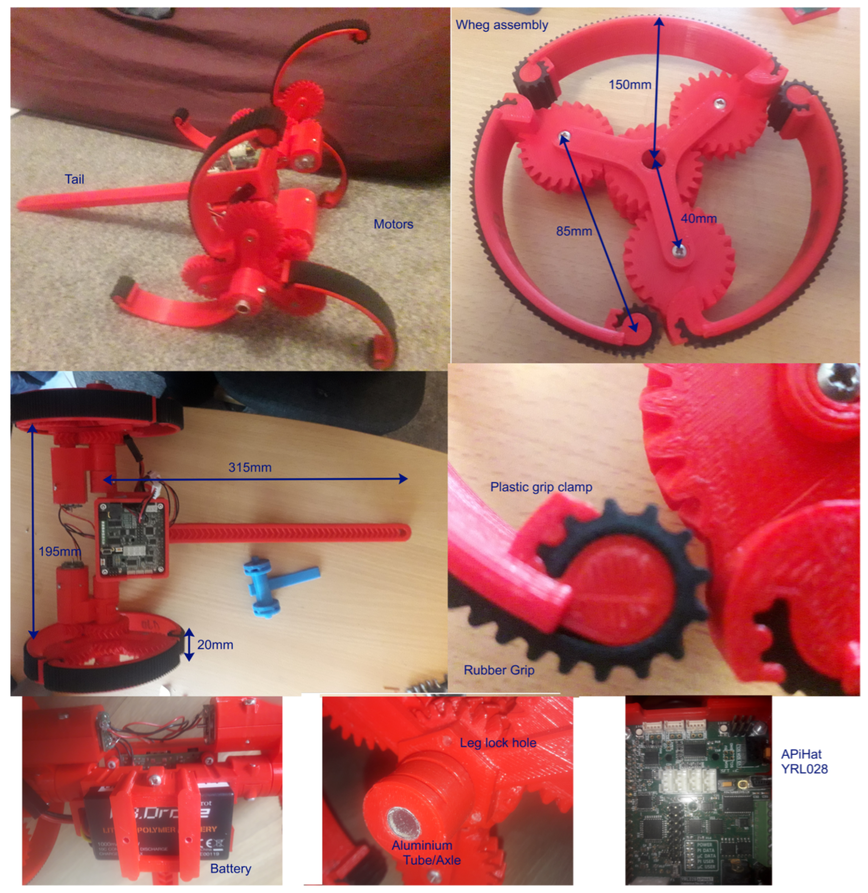
The curve of the legs allows them to have spring when pressure is applied to them similar to the legs of the R-Hex [
6]. The spring allows the robot to absorb impact both from the natural step of the robot and from any falls that may occur. The rubber on the legs is held in by friction fit so that it can be replaced if necessary like a normal tyre (
Figure 1).
The herringbone gears allow smoother transmission of motor drive through the centre of the Wheg assembly and separate motors to prevent damage. The herringbone gearing is also applied to lock the tail in place to allow it to be manually adjusted. The legs can either be locked in place every 20 degrees or be allowed to be deployed by the direction drive. The legs are locked in place by a bolt which goes into holes in the wheel hub placed every 20 degrees. This is important for systematic testing of the robot’s capabilities. When these bolts are not present the robot can transform from using legs/wheels by using its own motors. For example, if the battery is at the bottom; driving the Whegs forward will deploy the legs and backward will turn them back into a single wheel. The opposite is true if the robot has the battery on top as it can operate in either orientation.
The majority of the robot is 3D printed. The robot is split into modular parts so that each has a reasonably short print time. This has two benefits, failed prints are mitigated and the improved parts can be iterated faster. Only a single set of bolts are required; all fixtures use the same M3 × 18 bolts. Aluminium tubes act as the main axles for the whegs and improve the robot’s structural integrity. They are attached to the plastic parts by friction based grip rings that use a single bolt.
3.2. Electronic Components
The battery is a 11.1V Parrot lithium battery, which is stepped down to power a Raspberry Pi 3 A+. This is a significant increase in memory and processing power from previous transformable Wheg robot that used micro-controllers [
12,
13] or tethered processing [
20]. The Pi is powerful enough to perform SLAM or utilise a camera for navigation. Attached to the Pi is APiHat from York Robotics Lab which allows motors to be controlled and any sensors to be connected. This hat streamlined the electronic design as all components became plug and play as shown in
Figure 2. Currently the robot is controlled by a Bluetooth joystick that supplies the speed of the two wheels as a Cartesian coordinate. The aluminium tubes allow electrical wiring to be on either side of the Whegs without a slip ring. Without this the Whegs cause blind spots for sensors. This, combined with the improved computing power, means that autonomous development is more achievable.
4. Linear Constraints for a Step
Understanding the theory of why a design has specific capabilities means the future applications can be predicted. The predictive model could then be applied to where a robot could be successfully deployed, what route it should take in an environment or how a different robot could be designed. This section explains how a surmount and approach theory can be used to bound the possible step height.
In [
2], a geometric approach was used to bound the ability to climb a single step. The robot had wheels made of 6 legs/spokes with a tail where the length of these legs plus the length of tail were varied. This means that retracting the legs does not transform them into a smooth wheel. The reason given for retraction was to fit through smaller gaps during disaster rescue.
The theory split the ability to traverse a step into two phases: approach and surmount. The approach phase was the ability of the robot to achieve a leg purchase on the step to lift itself up. This assumed the Wheg would be able to rotate at the base of the step. In the three legged case the length of the side of the equilateral made by the ends of each leg. The surmount was then the ability to pull the rest of the robot and tail over the step. This was calculated by subtracting the leg radius from the tail length and was determined by whether the tail remained on the ground when the legs lifted the robot up the step.
The geometric procedure simplifies the robot legs and tail into lines for ease of calculation. It assumes that the top of the step and the foot of the leg with have ideal friction between. There is no consideration of energy or torque so whether the motor will be powerful enough to lift the robot. Because of all of this it is a theoretical maximum that could be traversed with a given leg and tail length. Hence it is a linear constraint like those found in linear programming.
Two linear constraints were generated by Equations (
1) and (
2). In these equations
H is the height of the step,
R is the radius of the wheels and L is the length of the tail from the centre of the Whegs. Here,
k depends on the number of legs in the Wheg,
for three legs and
for the six legs. Only six legs was tested in this paper. Equation (
1) is based on whether the end of the leg can reach the top of the step. Equation (
2) can be simplified to whether the tail is longer than the step plus the legs.
This theory creates a linear bounding region for the robots ability to climb a step as shown in
Figure 3. If the robot’s current configuration and step height is below both these lines then it is possible for it to climb the step. This theory was tested against a six legged hardware platform in [
2] and a ratio for three legged robot only theoretically proposed. The approach/surmount theory will be validated by the data gathered with the Cylindabot for both simulation and hardware. Showing there is little reality gap for this sort of obstacle traversal.
5. Simulation
In order to assess the feasibility of the approach, the first stage was to develop and test the design in simulation. Being able to simulate allows for a high degree of experimentation before construction, thus saving time and construction costs. Work in this section outlines the simulation approach, along with experimental results that have helped inform the development of Cylindabot.
5.1. Method
The simulation setup uses CoppeliaSim (previously known as V-Rep) for its Python API and easy to access GUI. The code was split between a Lua script which handled creating the terrain feature and a python program that controlled the simulation and the robot’s movement. A simulation scene was designed to use two tiles with a square meter gap between them, in this gap a terrain obstacle is generated (
Figure 4). The two basic obstacles used here are a slope and a step. The slope is a height field and the step is a simple static cuboid at a given height. The CoppeliaSim scene (simulation environment) and Cylindabot robot model can be found in the
Supplementary Materials as well as the code for controlling them.
The controller for the robot is a simple differential drive that is attempting to move the robot to the centre of the finishing tile. It takes the robot’s position to give an target angle direction and uses the robot’s orientation to adjust wheel speeds to head in that direction by the turn angle. This is a proportional controller that subtracts from the wheel speed on the side it needs to turn towards, as shown in Equation (
3). It is possible that this becomes negative, allowing the robot to turn on the spot if facing more than 90 degrees from the target direction. The controller was part of main python loop and ran at approximately 100 Hz.
The selection of difficulty of the obstacle uses a method nicknamed the ‘beermat’ method. If the robot is successful the result is recorded and the difficulty is increased or if it fails then difficulty is decreased (both in increments of 1 mm). To initiate this in the right region the difficulty is increase to a point the robot has failed at least once in an increment of 1 cm. Whereas [
14] had to repetitively test at difficulties both too easy and difficult. The ’beermat’ algorithm allowed the robot to be repeatedly tested at the correct difficulty while saving the number of runs required.
The robot model is created using only primitive shapes (spheres, cuboids, or cylinders) as the physics interactions are more realistic. The curved legs are created using 20 cuboids that are then joined together (
Figure 5) and at the ends there were 3 cylinders used. The main body, leg holders and tail were also made with a combination of cuboids and cylinders. These primitives were then composited together using a group function when they were not meant to move relative to each other. Revolute joints were used to connect the legs to the Wheg assembly and the whole Wheg to the main body. Finally a linear joint was used to control the tail position. This is all designed to match the physical design as closely as possible, while still giving robust physical interactions. In
Section 6 the close correlation between simulated and hardware results are shown. The two main parameter changes made to achieve this were setting the strengths of the revolute joints high enough to take Wheg based movements and setting the frictional coefficient to 1.35 (see
Table 2).
Two geometrically simple obstacles are analysed here: a single step and a slope. In the graphs, a small icon is used to distinguish the difference in the top right corner. The step can be analogous to a jagged surface. The slope is used to represent smooth surfaces and interactions. A smooth surface could be measured by its steepest point. By this argument a robot’s ability on a step and a slope can generically represent its ability on a range of terrains.
5.2. Results—Single Steps
The ability to climb up a single step is a good measure of the robot’s capacity to negotiate unfavourable terrain by bypassing it using legs. In this case, that step is an increasingly taller metre square cuboid. The theoretical hypothesis is that increasing Wheg deployment and tail length should improve the height of the step that can be traversed. The results here are given over 50 successful runs using the ’beer mat’ method. Initially the step results were mapped against the angle of the leg along the x-axis as this is how the legs deploy (by rotation). Due to the approach and surmount theory in [
2] they were remapped to the radius of the legs from the axle of the wheel. To fully realise the potential step climbing, longer tail lengths were added, not seen in the slope or hardware results.
In
Figure 6, the upward trend line up for all different tail lengths are illustrated. At various points the leg radius reached a break point where the ability trailed off. The downwards trends are parallel to each other. This demonstrates the approach and surmount lines, which helps support this theoretical model. The maximum deployment of the leg and tail fall just short of an urban environment standard. In the UK the maximum rise of a step is 220 mm.
The upward trend shows where the edges of the Wheg catch on the step and are able to lift the robot (1. approach). This is not the same as completely climbing the step and there are three outcomes which depend on the length of the tail. If the tail is shorter than the leg radius and step height, then the robot will fall over backwards (2. fall backwards). Next, if the tail is only a little bit longer than the legs, they will not be able to get enough purchase on the step and the weight of the robot will be in the tail (3. no grip). Finally, if the tail is long enough the robot will be able to pull itself up the step (4. surmount). These are shown in
Figure 7.
Statistics on Step Data
To test the statistical significance of these data (
Figure 6) two algorithms were applied, the
T-test and Cohen effect size. These were carried out for a reference configuration of the robot with the legs retracted into a wheel at a radius of 75 mm and tail set to 190 mm. Three different states were tested fully deployed legs with retracted tail, tail extended but leg retracted, and both legs/tail fully deployed. The
P-values was effectively zero and the effect size reached 73.2. The data show that increasing the tail length and leg radius concurrently improve the performance on steps. Hence the ideal configuration of the robot is to have both the tail and legs extended when going over step or a jagged environment.
Hypothesis 0 (H0 null). Leg and tail deployment has no effect on the robot’s maximum ability to traverse a step.
Hypothesis 1 (H1 alternative). Having longer legs and tail improve the robot’s maximum ability to traverse a step.
5.3. Results—Flat Slopes
Slopes are used to mimic smooth interaction with different terrain features. It is expected that the legs will be a hindrance in getting up a slope as they will move the mass of the robot further away from the surface. Data in
Figure 8 show that the deployment of the legs has a negative impact on the robot’s slope ascending ability. The different tail lengths still produce parallel lines. The main feature that causes failures here are the legs slipping against the slope. Similar to the steps results, these needed to be remapped to a different domain. In
Figure 8, the mid-point of the leg radius was used instead of its maximum. This remapping mostly affects the results when the legs are fully deployed. As at this point the maximum radius does not significantly increase but the amount of curve does. The curved nature of the legs is salient to the robot’s ability on slopes.
Statistics on Slope Data
In the same way as with step a statistical analysis was made between the fully retracted configuration of the robot and different part being deployed. This time the tail only reached 340 mm in length. The
P-values were again extremely small, meaning that we can reject the null hypothesis. The effect size being largest when the tail is full deployed and the Wheg are retracted into wheels. The statistical results and the raw data values can be found in the
supplementary material.
For both a step and a slope it is better to have the tail as long as possible. The fact that this shows that when the legs are retracted the robot is more capable on slopes is crucial. It means there is a need to use wheels for certain terrain types. Both configurations are useful depending on the situation.
Hypothesis 2 (H2 null). Leg and tail deployment has no effect on the robot’s maximum ability to traverse a slope.
Hypothesis 3 (H3 alternative). Having shorter legs and a longer tail improve the robot’s maximum ability to traverse a slope.
6. Hardware Experiments
The next step is to see if these simulation result match up with the real world. The previous results need to be validated on hardware to see if there is any reality gap between the two sets of results. One of the key differences between the simulated and real robot was the leg and the fact that they are able to flex under impacts and the small ridges in the rubber were not simulated. For this both a step and slope needed to be constructed
Figure 9, these were not able to configured to the same increments as simulation. The robot was human operated rather than autonomously using its position and the success or failure was due to a human observation. The robot’s movement was controlled using a Bluetooth joystick. The Cartesian position of the analogue stick was fed directly to the motor speeds. As only two motors were required in the design, this allowed full control of movement.
The data produced are more discrete because of physical limitations. What this means is that the increments that the robot and obstacles can be configured in are larger. So there are fewer points on the graph and there relative inaccuracy is increased. The legs can only be locked into eight positions with 20 degrees between the positions that are not the end positions. The step height and slope adjacent size can only be altered in increments of 1 cm. This is represented in the y-axis of the graphs being measured in centimetres.
6.1. Single Step Results
In graph,
Figure 10 the trend is still upward until it peaks. This peak is caused by the length of the tail when the robot starts to fall backwards. One key difference in simulation and hardware results is when the legs are fully retracted the robot is not able to surmount a step as high as it did in simulation. The green and blue lines represent the approach and surmount limits. The green line is a little higher than the actual results as this was a theoretical maximum. It assumed infinitely thin straight legs and they always gained purchase on the step. Likely that the curve of the leg prevented reaching this value. The error bars for the simulated data shows the full range of results which have a relatively small variance. The simulated and physical results follow each other well and it is probable that it is simply the accuracy constraints that cause the disparity.
6.2. Simple Slopes Results
The biggest divergence between simulation and the real world in graphs,
Figure 11 is that the legs are fully retracted. This backs up the assumption that smooth continuous drive is better for a slope, i.e., a wheel or track. Again the simulation and hardware results match each other for most of the plot with the exception of full retracted legs. This reality gap however does follow the hypothesis that legs suit a step and wheels suit a slope. There is no trend line presented as more work is needed that take into account the friction between the robot and the surface of the slope.
6.3. Reality Gap
In
Figure 10 and
Figure 11, the R-squared values are given for how close the hardware results match the simulation. The main deviation occurs when the legs are fully retracted into a wheel. For the calculation of these values the linear interpolation was used for
off the simulated results and the mean of the hardware results for total error. The generated values show a strong to fair correlation between the simulated and real results. In particular the results for steps when the tail is set to 315 mm. This shows that the simulation for these specific obstacles was able to accurate model the maximum difficulty that could be traversed.
7. Discussion
Several examples of robots with transformable wheels can be found in scientific literature. One of the most recent is the WheeLeR robot [
13] which deployed a passive leg system. The drive of the motors was applied to a cog so that the legs extend when driven in one direction and retracted when driven in the other. A passive mechanic is applied in [
16], a catch that protrudes from the wheels and when the wheel is driven in one direction it releases the legs. In the Impass robot [
20] the legs are actuated linearly through the axle rather than the rotation used in this work and achieve the higher step ratio. The LEON robot [
21] has two wheels that transform into legs and augment four other legs to allow it to walk as a hexapod. Lastly, the Whegs robot [
19] has four Whegs made up of three legs in each Wheg that are represented in simulation by cuboids. The fact these legs do not deploy does put it at a disadvantage when it comes to the step ratio comparison.
In
Table 3, the step ratio is calculated by taking the maximum step that can be surmounted, divided by the robot’s height (legs not deployed). This means these results are agnostic to the size of the robot and are relative to the design capabilities. The only robot to outperform the Cylindabot was Impass robot with its linearly pushed legs able to reach a taller step. Although it lack the ability for roll smoothly which will hinder is movement on smooth surfaces. Overall Cylindabot has been able to perform well against similar robotics platforms. As for these measurement being used as a benchmark to compare robots, the step height a robot can climb over is often recorded. Here, that was converted into step ratio to make for a fair comparison. However although slopes are still a simple obstacle the frictional coefficient is difficult to standardise between different institutions and could be the reason it is less commonly documented. Further investigation is needed to see if the linear trends in
Figure 8 can be converted into a general theory including the frictional coefficient of the slope.
There are two key limitations to the Cylindabot platform, the lack of sensors and the dynamic control of the leg/tail deployment. Firstly although the Cylindabot is large enough and has processing power to act autonomously it does not have the sensing capability to do so. Once the robot is able to determine what is around it will then have to determine which mode (wheeled or legged) it will traverse the environment like the action planner in [
21]. Secondly, the physical prototype can only change between full wheel or leg mode without human assistance and the tail has to be set to different positions manually unlike the variable diameter robot from [
2]. Although it is not clear if they achieved full dynamic reconfiguration to achieve the under/over capabilities of the Rising Star [
12], shown in their video. It has been shown that wheels or legs are suited to different obstacles so it is reasonable to assume that being partially deployed between to two might be advantageous. An environment made of a mix of smooth and jagged surfaces for example.
8. Conclusions
Steps and slopes are simple geometric obstacles that are often found in real environments and, hence, can act as a benchmark to assess a robot’s capabilities to move within an environment with various terrains. A novel robot design is introduced in this paper, the Cylindabot which uses an adaptive locomotion mechanism combining wheels and legs. The Cylindabot design enables it to locomote in various environments. The step height ability adheres to the approach/surmount theory. On a slope, results were also made linear by calculating the mid-point leg radius. This work suggests that the theory introduced in the paper can be used in robot designs of any size to determine their abilities to manage slopes and steps within a given environment. This can be backed up by simulation runs before moving to hardware experiments. The experimental results presented in this paper indicate that the Cylindabot is competitive with other similar platforms and outperforms all if slopes and step performance are considered together. Finally there is a need for both wheels and legs depending on the terrain for the robot to perform optimally.
In future work, the correlation between simple obstacles with more complex environments will be considered. Is it possible for performance on a simple obstacles predict how a robot does in a general. Plans are to add time of flight (ToF) lasers, a camera, and an inertial measurement unit (IMU) to allow the robot to sense its environment, then be able to adapt itself autonomously. This sensing is facilitated by the aluminium tubes which act as the axle hubs of both Whegs. Further testing on a wider range of real terrain is needed, which is partially performed in the
Supplementary Video.
Supplementary Materials
The following are available online at
https://github.com/rw1445/Cylindabot-sim, Python code for creating obstacles: (createterrain2.py, designing_terrain.py, terrain_heightsNew.py), Python code for controlling the simulation: Controlterrain.py, CoppeliaSim model of cylindabot: Cylindabot Model.ttm, CoppeliaSim Scene of the simulation: terrain test ground (new friction) sep20.ttt, Simulation data in a compressed file: MDPI data.zip, Statistical results: Stats result.jpg. In addition there is a video abstract is available at
https://youtu.be/KrRDXtn1vRQ.
Author Contributions
Conceptualization, R.W.; methodology, R.W.; software, R.W.; validation, R.W.; formal analysis, R.W.; investigation, R.W.; resources, R.W.; data curation, R.W.; writing—original draft preparation, R.W.; writing—review and editing, J.T. and A.M.T.; visualization, R.W.; supervision, J.T. and A.M.T.; project administration, R.W.; funding acquisition, A.M.T. All authors have read and agreed to the published version of the manuscript.
Funding
The authors would like to thank the EPSRC and the Department of Electronic Engineering, University of York, for partial funding of this work.
Institutional Review Board Statement
Not applicable.
Informed Consent Statement
Not applicable.
Data Availability Statement
Conflicts of Interest
The authors declare no conflict of interest.
References
- Schroer, R.; Boggess, M.; Bachmann, R.; Quinn, R.; Ritzmann, R. Comparing cockroach and Whegs robot body motions. In Proceedings of the IEEE International Conference on Robotics and Automation, New Orleans, LA, USA, 26 April–1 May 2004; Institute of Electrical and Electronics Engineers (IEEE): New York, NY, USA, 2014; pp. 3288–3293. [Google Scholar] [CrossRef]
- Nagatani, K.; Kuze, M.; Yoshida, K. Development of a Transformable Mobile Robot with a Variable Wheel Diameter. J. Robot. Mechatron. 2007, 19, 252–257. [Google Scholar] [CrossRef]
- Seok, S.; Wang, A.; Chuah, M.Y.; Hyun, D.J.; Lee, J.; Otten, D.M.; Lang, J.H.; Kim, S. Design principles for energy-efficient legged locomotion and implementation on the MIT Cheetah robot. IEEE ASME Trans. Mechatron. 2013, 20, 1117–1129. [Google Scholar] [CrossRef] [Green Version]
- Raibert, M.H.; Brown, H.B.; Michael Chepponis, J. One-Legged Hopping Machine; Technical Report; MIT: Massachusetts, MA, USA, 1984. [Google Scholar]
- Yim, J.K.; Fearing, R.S. Precision Jumping Limits from Flight-Phase Control in Salto-1P. In Proceedings of the 2018 IEEE/RSJ International Conference on Intelligent Robots and Systems (IROS), Madrid, Spain, 1–5 October 2018; IEEE: New York, NY, USA, 2018. [Google Scholar] [CrossRef]
- Saranli, U.; Buehler, M.; Koditschek, D.E. RHex: A Simple and Highly Mobile Hexapod Robot; Technical Report; University of Michigan: Ann Arbor, MI, USA, 2001. [Google Scholar]
- Galloway, K.C.; Clark Haynes, G.; Deniz Ilhan, B.; Johnson, A.M.; Knopf, R.; Lynch, G.A.; Plotnick, B.N.; White, M.; Koditschek, D.E.; Haynes, G.C.; et al. X-RHex: A Highly Mobile Hexapedal Robot for Sensorimotor Tasks Recommended Citation X-RHex: A Highly Mobile Hexapedal Robot for Sensorimotor Tasks; Technical Report; University of Pennsylvania: Philadelphia, PA, USA, 2010. [Google Scholar]
- Roberts, S.; Zobeck, T.M.; Koditschek, D.; Duperret, J.; Johnson, A.M.; Van Pelt, S.; Zobeck, T.; Lancaster, N.; Koditschek, D.E. Desert RHex Technical Report: Jornada and White Sands Trip; Technical Report; University of Pennsylvania: Philadelphia, PA, USA, 2014. [Google Scholar]
- Barragan, M.; Flowers, N.; Johnson, A.M. MiniRHex: A Small, Open-Source, Fully Programmable Walking Hexapod; Technical Report; Carnegie Mellon University: Pittsburgh, PA, USA, 2018. [Google Scholar]
- Kim, R.; Debate, A.; Balakirsky, S.; Mazumdar, A. Using Manipulation to Enable Adaptive Ground Mobility. In Proceedings of the 2020 IEEE International Conference on Robotics and Automation (ICRA), Paris, France, 31 May–31 August 2020. [Google Scholar]
- Hougen, D.; Benjaafar, S.; Bonney, J.; Budenske, J.; Dvorak, M.; Gini, M.; French, H.; Krantz, D.; Li, P.; Malver, F.; et al. A Miniature Robotic System for Reconnaissance and Surveillance; ICRA: New York, NY, USA, 2000. [Google Scholar] [CrossRef]
- Zarrouk, D.; Yehezkel, L. Rising STAR: A highly reconfigurable sprawl tuned robot. IEEE Robot. Autom. Lett. 2018, 3, 1888–1895. [Google Scholar] [CrossRef]
- Zheng, C.; Lee, K. WheeLeR: Wheel-Leg Reconfigurable Mechanism with Passive Gears for Mobile Robot Applications; ICRA: New York, NY, USA, 2019. [Google Scholar]
- Sun, T.; Xiang, X.; Su, W.; Wu, H.; Song, Y. A transformable wheel-legged mobile robot: Design, analysis and experiment. Robot. Auton. Syst. 2017, 98, 30–41. [Google Scholar] [CrossRef]
- She, Y.; Hurd, C.J.; Su, H.J. A Transformable Wheel Robot with a Passive Leg.. International Conference on Intelligent Robots and Systems; IEEE: New York, NY, USA, 2015. [Google Scholar] [CrossRef]
- Kim, Y.S.; Jung, G.P.; Kim, H.; Cho, K.J.; Chu, C.N. Wheel Transformer: A wheel-leg hybrid robot with passive transformable wheels. IEEE Trans. Robot. 2014, 30, 1487–1498. [Google Scholar] [CrossRef]
- Chen, W.H.; Lin, H.S.; Lin, Y.M.; Lin, P.C. TurboQuad: A Novel Leg-Wheel Transformable Robot with Smooth and Fast Behavioral Transitions. IEEE Trans. Robot. 2017, 33, 1025–1040. [Google Scholar] [CrossRef]
- Chen, S.C.; Huang, K.J.; Chen, W.H.; Shen, S.Y.; Li, C.H.; Lin, P.C. Quattroped: A Leg—Wheel Transformable Robot. IEEE ASME Trans. Mechatron. 2013, 19, 730–742. [Google Scholar] [CrossRef]
- Taylor, B.; Balakirsky, S.; Messina, E.; Quinn, R. Design and Validation of a Whegs Robot in USARSim. In Proceedings of the Workshop on Performance Metrics for Intelligent Systems, Washington, DC, USA, 28–30 August 2007. [Google Scholar]
- Jeans, J.B.; Hong, D. IMPASS: Intelligent Mobility Platform with Active Spoke System. In Proceedings of the IEEE International Conference on Robotics and Automation, Kobe, Japan, 12–17 May 2009; Institute of Electrical and Electronics Engineers (IEEE): New York, NY, USA, 2009; pp. 1605–1606. [Google Scholar] [CrossRef]
- Rohmer, E.; Reina, G.; Yoshida, K. Dynamic simulation-based action planner for a reconfigurable hybrid leg-wheel planetary exploration rover. Adv. Robot. 2010, 24, 1219–1238. [Google Scholar] [CrossRef]
- Bhounsule, P.A.; Ameperosa, E.; Miller, S.; Seay, K.; Ulep, R. Dead-Beat Control of Walking for a Torso-Actuated Rimless Wheel Using an Event-Based, Discrete, Linear Controller. In Proceedings of the ASME 2016 International Design Engineering Technical Conferences and Computers and Information in Engineering Conference, New York, NY, USA, 21–24 August 2016. [Google Scholar] [CrossRef] [Green Version]
| Publisher’s Note: MDPI stays neutral with regard to jurisdictional claims in published maps and institutional affiliations. |
© 2021 by the authors. Licensee MDPI, Basel, Switzerland. This article is an open access article distributed under the terms and conditions of the Creative Commons Attribution (CC BY) license (https://creativecommons.org/licenses/by/4.0/).


