1. Introduction
Resilient robots are robots that are able to recover their original function after partial damage [
1,
2]. Recovery refers to recovery strategies, i.e., the principle that governs a recovery process. Three recovery strategies have been proposed in our previous work [
1]: Strategy I: Training a remaining system to perform a new behavior, e.g., regeneration of a control system; Strategy II: Changing the configuration of a system by re-arranging its components, which is the reconfigurable robot; Strategy III: Changing component states, e.g., changing the length of a component. Combining the above three recovery strategies results in a general resilient robot. This paper will be focused on an underactuated resilient robot. After suffering partial damage, a damaged robot finds the target configuration, upon which the damaged robot can still function. It should be noted that there are many possible target configurations and finding the optimal target configuration is called configuration synthesis. Configuration synthesis is to generate the optimal configuration to achieve a given task. The task is to enable a robotic arm to reach every point of its workspace. The work in [
3] used a sequential design procedure based on a traditional kinematic model for the configuration design of their modular manipulator. Similarly, the work in [
4] used D-H parameters as design variables with joint limitations as design constraints to design their reconfigurable modular manipulator. The traditional kinematic model does not apply to the configuration synthesis of modular robots when the number of modules is big. The work in [
5] defined design variables including the number of joints, type of joints, number of links, type of links, and the link assembly patterns, which are all discrete variables. In their work, workspace reachability, joint range availability, and manipulability were defined as design constraints. The minimal degree of freedom (DOF) was considered as a design objective, which expresses a desire for fewer active modules if possible. The work in [
6,
7] used a concurrent optimal design approach, which explores the configuration space in terms of number, type, and dimension. Continuous variables (i.e., the base location and the length of links) were included in their optimization problem, along with discrete variables that represent the topology of the configuration. The minimum energy consumption was considered as the objective function. The work in [
8] searched for the optimal configuration using a two-level genetic algorithm.
Another type of task specification is to achieve the fault tolerance of a robot (i.e., to synthesize the configuration that can continue the task after faults). Faults can be classified into actuator faults, sensor faults, and component faults [
9]. The present paper focuses on actuator faults and joint faults only. Specifically, the active joints may be locked or unlocked due to the loss of control actions. Passive joints may be locked due to being stuck in the interface. Note that modular robots more easily suffer from these faults than other robots [
6]. Regarding the fault-tolerant configuration, the key point is the evaluation of fault tolerance, which is the quantification of fault tolerance.
Identifying the fault-tolerant configuration avoids precarious configurations and identifies new workspace boundaries. The work in [
10] introduced manipulability for measuring fault tolerance. The work in [
11] proposed an approach to measure the fault tolerance for kinematically redundant serial manipulators. Further, the work in [
12,
13] proposed the measure of the fault tolerance of a robot. The work in [
5] proposed an agent-based approach to achieve “fault tolerance” by changing the assembly patterns and increasing the number of joint modules. However, a general method for configuration synthesis is lacking due to the architecture limitation.
The main contribution of this paper is a computational model of configuration synthesis of an underactuated resilient robot. First, we analyze the architecture of the underactuated resilient robot, including a rigorous analytical formulation to define the configuration, a genetic algorithm to identify the optimal configuration, and an application of the proposed approach, see
Figure 1. Second, we give a computational model of the configuration synthesis problem for the proposed architecture. Third, a design case is given to demonstrate how the proposed model work. It is noted that the concept of configuration synthesis for the underactuated resilient robot was first proposed in our previous work [
14]. Compared with [
14], the present paper gives the detailed design of the resilient robot, the corresponding configuration synthesis model, and a detailed experiment to illustrate this model.
The paper is organized as follows.
Section 2 introduces the general architecture of the underactuated resilient robot.
Section 3 presents the configuration synthesis model.
Section 4 gives the implementation using a genetic algorithm. The configuration synthesis is demonstrated by an example in
Section 5.
Section 6 outlines the conclusions and future work.
2. General Architecture of an Underactuated Resilient Robot
As discussed in
Section 1, there are three recovery strategies, i.e., behavior changing, configuration changing, and component changing. Behavior changing requires that a system performs one function based on many different states or configurations. Configuration changing requires that two components can be connected and disconnected to change into different configurations. Component changing requires that the component length is adjustable. Since there are links, active and passive joints, and all modules can connect to achieve configuration changes, this robot is called an underactuated resilient robot. The general architecture of the resilient robot is detailed as follows.
- (1)
An underactuated resilient robot consists of two types of fundamental modules, passive modules (
Figure 1a) and active modules (
Figure 1b). There are active joints and passive joints (
Figure 1d). A link is formed by two modules with a fixed connection, which is called an adjustable link (
Figure 1e).
- (2)
All the modules are structured to have two pairs of docking systems on each of the four sides. The servomotors on each active module are the power supply of both locomotion and reconfiguration.
- (3)
A robot changes its configuration through a series of docking actions (
Figure 1c) between two modules, i.e., locking (forming a fixed connection) and unlocking (forming a passive joint), and disconnection (separation).
- (4)
The male interfaces of active modules provide actuation for both locomotion and reconfiguration.
Both linear and rotation motion are required to connect a female interface and a male interface. To connect a pair of the docking system, the male interface of one module is engaged to either Layer 1 or Layer 2 of the female interface of another module along Slot 1. To release, the male interface is driven to this slot and released to disengage with the female interface. When a male interface inserts along Slot 1 and rotates to Layer 1 of a female interface and is released, the two interfaces are connected to form a passive joint, see
Figure 1d. Rotate the male interface to Slot 1 and release the male interface, and the two interfaces are disconnected, and the passive joint is disassembled.
When a male interface is pushed along Slot 2 and rotated, it will be spring-backed to the position between two teeth, and the two modules are locked and become a rigid link, see
Figure 1e. The length of the new link can be adjusted by changing the relative angle between two modules, i.e., unlocking the connections (i.e., pushing the male port to the bottom of the female interface) and then locking the connection (i.e., releasing when the male interface is rotated between another two teeth). The adjustable length of a link formed by two modules is represented by a shadowed box in
Figure 1e. The adjustable connection can be disassembled by rotating the male interface to Slot 2 and then rotating to Slot 1 and then releasing the male interface. It is noted that there are male sides on Slot 1 and 2 to prevent the male interface from accidentally slipping out of Layer 1 if the bits of the male interface are aligned with the slots, see
Figure 1c.
One advantage of this architecture is that the cost is reduced as the reconfigurations share the same motor with locomotion. Also, the whole system has a relatively low energy consumption due to the passive joints. Another advantage is that the system is more resilient as the modules can change their roles based on the docking system instead of rendering the module or even the whole system useless. For instance, this robot can deal with two types of common failures, i.e., joints are locked and unlocked, as these two types of failures can be viewed as the adjustable link (for a failure of a locked active joint) and the passive joint (for the failure of the unlocked active joint).
3. Configuration Synthesis
The architecture of a system determines its configuration as the architecture specifies the properties of components. The configuration determines what and how these components are distributed. To determine a target configuration, the representation of the configuration is the first step.
3.1. Configuration Representation
In this paper, a configuration describes the kinematic connections between modules, including both types of modules and connections. We use a matrix to represent the configuration. Each row and each column represent modules. If there are m modules in an assembly, the matrix is m × m. Each element represents how two modules or objects are connected, namely, the information on the connection ports and the connection type. Note that there are two types of connections: fixed connection or relative motion.
Therefore, each element in the matrix has five numbers that give information of the ports of the two respective modules in connection. For instance, for row p and column k, the element has the following format <i1, i2, i3, i4, i5>, where i1 represents the type of Module p. i2 represents the port of Module p, which will be connected with Module k. Similarly, i3 and i4 represent the type of Module k and the port of Module k that will be connected with Module p. Note that i1 and i3 are “1” or “2”, where “1” means link and “2” means active joint. Both i2 and i4 are “1”, “2”, “3”, or “4”, which represent the port ID on one module. The last number, i5, denotes the connection type of Module k and Module p. Particularly, i5 is “1” or “2”, where “1” means passive connection or joint and “2” means fixed connection or joint. Note that the element (i, j) takes 0 if Module i and Module j are not connected.
Based on the above description, the matrix is diagonal.
Figure 2 shows the matrix representation for the robot shown in
Figure 3.
Figure 2.
The representation of the configuration in
Figure 4.
Figure 2.
The representation of the configuration in
Figure 4.
In
Figure 2, the element in row 1 and column 2 has the following meanings. The first number, 2, means that Module 1 is an active joint module. The third number, 1, means that Module 2 is a link module. The second number, 4, and the fourth number, 2, mean that Port 4 of Module 1 connects Port 2 of Module 2. The fifth number, 2, means that this connection is fixed.
3.2. Variables
Configuration synthesis involves formulating an optimal configuration to achieve a given task. The variables, constraints, and objectives are included. This paper focuses on configuration synthesis for task-oriented underactuated resilient robots. Specifically, the task is defined as a set of points in the workspace that is followed by the end-effector without loss of the generality of discussions.
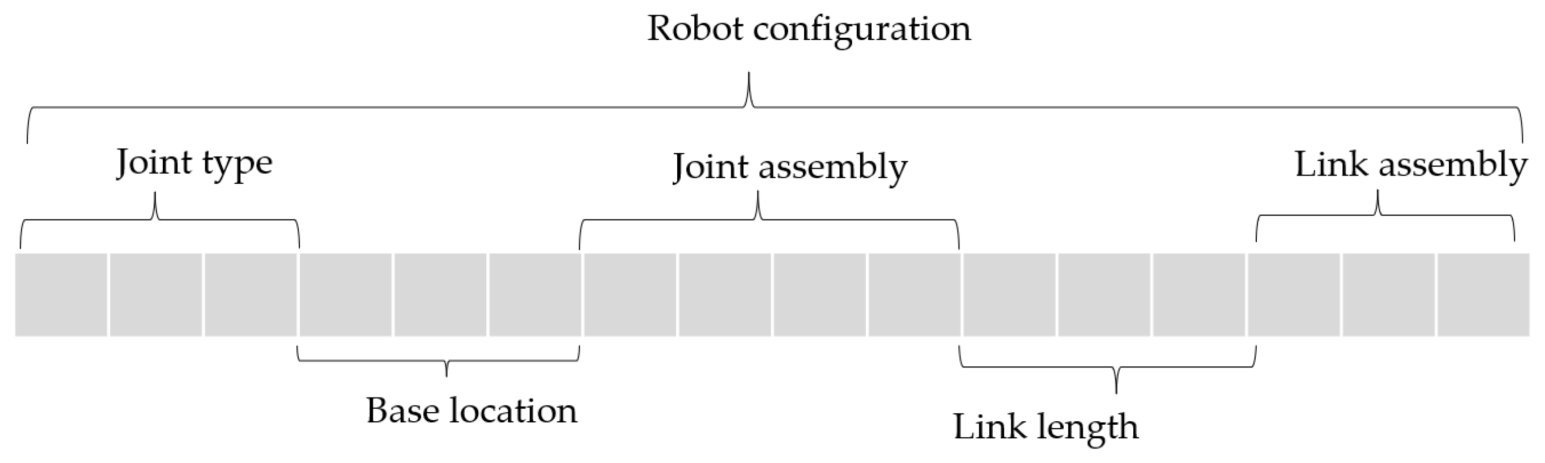
A configuration is determined by the variables. These variables are coded sequentially, and the code thus represents the configuration of a robot, including the kinematic and dynamic variables or parameters of the robot. Specifically, the variables include (1) the joint type; (2) the assembly pattern; (3) the lengths of links; and (4) the base location. Note that the first two variables are discrete, and the latter two are continuous variables. It is noted that assembly pattern is the type of the assembly between two ports. There are six assembly patterns. Each module has two femal ports (Port 1 and Port 2) and two male ports (Port 3 and Port 4). Port 1 of Module 1 connects Port 3 or Port 4 of Module 1, and Port 2 of Module 1 connects Port 3 or Port 4 of Module 2. Port 1 of Module 2 connects Port 3 or Port 4 of Module 1, and Port 2 of Module 2 connects Port 3 or Port 4 of Module 1. Thus, there are eight assembly patterns.
Figure 3 shows an example of a configuration determined by the above variables. The robot is a 3-DOF robotic manipulator with two active joint modules and three link modules. The variables are marked in
Figure 3, along with the explanation of the variables.
3.3. Constraints
Constraints achieve the feasibility of a robot configuration for performing a given task. In this paper, both kinematic and dynamic requirements will be considered. The kinematic constraints restrict the mobility direction, and the dynamic constraints achieve the dynamic balance [
16]. Different configurations have different kinematic and dynamic parameters. The method of the automatic generation of D-H kinematic and dynamic parameters was studied, which can be referred to in the previous work [
6,
17].
For an underactuated robot, the kinematic relationship among θ
a, θ
p, and x is expressed using the Jacobian matrix [
18]:
where θ
a, θ
p is the generalized coordinate for active and passive joints, respectively. x is the position of the end-effector. x = [x
1, x
2, …, x
m]
T, and is the given task (i.e., points). J
a and J
p are the Jacobian matrices for the active and passive joints, respectively.
The dynamic model for fully actuated robots [
12] is similar to underactuated robots, which is generally expressed as follows:
where H
aa, H
ap, and H
pp are inertia matrices. b
p and b
a are centrifugal, Coriolis, and gravity forces on passive and active joints, respectively. τ
a is the vector of torques on active joints.
The kinematic requirement of joint
j at the task point
i is modeled as
where
and
are the displacement limits.
The forces/torque on the joint modules can be obtained if the payload at the task space for a point
k is given. The described payload,
fi, is modeled as follows by the following constraints:
where
is the maximum driving force/torque that a joint module generates.
3.4. Objectives
There are two types of criteria used to evaluate the robot configurations: manipulability and energy consumption. Manipulability is defined as “the ability to position and orient the end-effector” in [
10]. Here, the dynamic manipulability in [
12] is used to quantify the manipulator’s dexterity.
where
denotes the robot dexterity whose passive joints are
. Note that the passive joints are considered to be free-swing joints.
denotes the matrix
H−1 with its
columns removed.
H and
J are the inertia matrix and Jacobian matrix of the fully actuated robot.
There are three types of failures for a resilient robot: (i) one or more active joints are locked, (ii) one or more active joints are unlocked, and (iii) some active joints are locked, and some are unlocked. The dynamic manipulability of a robot with these three types of failures can be expressed as
The superscript “
u” and “
l” represents unlocked active joints and locked active joints, respectively.
is the dexterity of the robot with unlocked active joints
and locked joints
.
denotes
H−1 whose
rows and columns are removed, and
columns are removed.
denotes the matrix
J with its
columns removed. The criterion of manipulability to be minimized is as
Passive joint decreases energy consumption. The index of the power consumption in [
19] is used as energy consumption in this paper.
where
E is the energy consumption along the desired trajectory,
n is the number of joints of a configuration;
Tra is the space consisting of all working points, and
τi(
θ) is the torque on joint
i.
The objective function for evaluating the configuration is as follows:
where
FG is the measure for a configuration candidate for a task.
k1 and
k2 are the two weights of manipulability and energy consumption, respectively.
5. Case Study
In this section, configuration synthesis will be illustrated using a 3-DOF underactuated robot.
Table 1 shows the task specification with five points along the desired trajectory. The robot should reach each of these points with null accelerations and speeds. One of the ports of the last links of the robot passes through the task points.
The user requires a 3-DOF robot to achieve the task so that there are three joints that could be passive or active. Therefore, the total design variables include (i) three variables for the joint types; (ii) three variables for the base location; (iii) three variables for the link length; and (iv) 3 − (m + 3) variables for the assembly pattern. m is determined by the length of links. For example, if m can be formed by two link modules, m is equal to 2. It is noted that the number of modules could be different in different configurations. For example, one single link module is enough when the length of a link is the same as that of a single link module.
This experiment served as an example of configuration synthesis for a robot that was under actuated. As indicated in
Table 1, the task specification calls for the manipulator to pass through five places. At each point, the acceleration and velocity are both zero. To complete the task, the user needs a 3-DOF robot with three joints that can be passive or active. As a result, the total design variables in the model of configuration synthesis are (i) three variables for joint type; (ii) three variables for base location; (iii) three variables for link length; and (iv) three—(
m + 3) variables for assembly pattern. The size of the linkages affects m. For instance, m is equal to 2 if
m can be constructed by two link modules. It is important to keep in mind that different configurations may have a varying number of modules. When the length of a link is equal to that of a single link module, for instance, one single link module suffices.
The genetic algorithm’s parameters are specified as follows for implementation. There are 100 samples in the initial population, and there are 100 samples in each subsequent generation. Overall, 100 generations are required for the GA program to terminate.
Figure 6 depicts the progression of the solution. Thirty generations later, the answer converged.
Figure 7 depicts the evolution of the design variables and demonstrates that after thirty generations, the design variables also converged.
Figure 8 shows the optimal configuration. In order to illustrate the configuration synthesis algorithm, two individuals with lower fitness compared to the optimal configuration, Configuration I and Configuration II, see
Figure 9. The two configurations are feasible to achieve the task. Each of them consists of more link modules and consumes more energy, as compared with the optimal configuration.
The algorithms were implemented in the Matlab platform. For the active modules, the torque of the actuator is 13.1Nm. The velocity is 3.768 m/s. The mass of the active and passive modules is 0.9 g and 0.33 g, respectively. The length of the module is 50 mm. The Matlab Robotic Toolbox and the GA Toolbox were used. The experiment was conducted on a PC with 2.40 GHz and 3.00 GB RAM. In the simulation, the parameters of the genetic algorithm are empirically set as follows.
6. Conclusions and Future Work
In this paper, an underactuated modular robot was presented. The architecture is featured that each module cannot be divided further and the fixed connection could be switched to the passive joint through a novel docking system. With the docking system, the minimum number of fundamental modules (i.e., active modules and passive modules) is needed, and the reconfiguration and locomotion share the same motor, thus increasing the overall resource utilization as well as reducing the cost.
In the GA-based configuration synthesis method, both continuous and discrete variables were included. The optimal configuration not only possesses the resilience ability but also consumes less energy. This approach was illustrated by a 3-DOF robot manipulator in the simulation. It was concluded that the configuration that includes passive joints reduces the cost.
There are, however, some issues that remain to be investigated considering the manufacturing difficulties. As was expected, gravitational deformation was the most severe problem. To reduce the complexity of the reconfiguration, we have not considered the passive docking, which is formed by a male interface from a passive module and a female interface from any other module, and this will be included in our next step. The mechanism must not only be stiff to reduce errors but also flexible to tolerate positioning errors. Furthermore, it is also important to consider more dynamic aspects of the whole system. The controller used for the robot in this paper is all centralized offline. In the future, other types of failures will be included, and the configuration synthesis model will be improved accordingly. In the future, we will fabricate physically resilient robots using the metal material and will test the configuration synthesis model on the physical robot. Finally, we will also formulate the synthesis problem using the topology optimization approach [
20] and the machine learning approach [
21].


