Article

Data-Driven Inverse Kinematics Approximation of a Delta Robot with Stepper Motors

Department of Mechanical Engineering, University of California, Merced, CA 95343, USA
*
Author to whom correspondence should be addressed.
Robotics 2023, 12(5), 135; https://doi.org/10.3390/robotics12050135
Submission received: 1 September 2023 / Revised: 28 September 2023 / Accepted: 28 September 2023 / Published: 30 September 2023
(This article belongs to the Special Issue Collection in Honor of Women's Contribution in Robotics)

Abstract

:
The Delta robot is a parallel robot that is over-actuated and has a highly nonlinear dynamic model, which poses a significant challenge to its control design. The inverse kinematics that maps the motor angles to the position of the end effector is highly nonlinear and extremely important for the control design of the Delta robot. It has been experimentally shown that geometry-based inverse kinematics is not accurate enough to capture the dynamics of the Delta robot due to manufacturing component errors, measurement errors, joint flexibility, backlash, friction, etc. To address this issue, we propose a neural network model to approximate the inverse kinematics of the Delta robot with stepper motors. The neural network model is trained with randomly sampled experimental data and implemented on the hardware in an open-loop control for trajectory tracking. Extensive experimental results show that the neural network model achieves excellent performance in terms of the trajectory tracking of the Delta robot under different operation conditions, and outperforms the geometry-based inverse kinematics model. A critical numerical observation indicates that neural networks trained with the specific trajectory data fall short of anticipated performance due to a lack of data. Conversely, neural networks trained on random experimental data capture the rich dynamics of the Delta robot and are quite robust to model uncertainties compared to geometry-based inverse kinematics.

1. Introduction

The Delta robot is an over-actuated parallel robot composed of three arms connected to an end effector and mounted on the base. Delta robots are known for their high speed, accuracy, and versatility, making them suitable for various tasks, such as assembly, pick-and-place, and classification. One key aspect of controlling a Delta robot is the dynamic model, which outlines the relationship between the joint inputs and the position of the end effector. There are several approaches to modeling the Delta robot. One of the most popular approaches is Lagrangian dynamics [1,2,3]. Another common approach to modeling the Delta robot is to use inverse kinematics [4,5], with the help of the geometry of the robot’s joints and links. Additionally, screw theory, which represents the motion of the robot in terms of screw axes and twists, has been adopted to model the dynamics of the Delta robot [6]. The dynamic model is essential for motion planning and trajectory tracking, as it allows the controller to calculate the required joint inputs to achieve a desired end effector position.
The inverse kinematics of the Delta robots describes the relationship between the input joint angles of the motors and the position of the end effector in 3D space. It turns out that the inverse kinematics in [4] cannot describe the algebraic relationship very accurately in hardware applications. Several factors lead to large tracking errors, such as manufacturing tolerances, assembly errors, joint flexibility, wear, and transmission errors [7]. Thus, it is important to model the Delta robot with high precision, accounting for the manufacturing errors and joint limits. In this study, neural networks are adopted to model the relationship between the joint angles and the position of the end effector. There are multiple ways to obtain the solution of inverse kinematics. Except for numerical solutions, algebraic solutions, geometric solutions, and neural networks have been extensively applied to construct the forward or inverse kinematics solutions of different manipulators [8,9]. Going back to the 1990s, researchers had already started adopting neural networks to address the under-constrained and ill-conditioned problems of inverse kinematics [10]. A radial basis function neural network is proposed in [11] to deal with the complexity involved in deriving the inverse kinematics solutions for a 7-DOF manipulator. The weighted least square method and the genetic algorithm are employed to search for the global optimum solution. More recently, neural networks have also been adopted for the real-time computation of the direct kinematic problem of the 3PRS robot [9]. Ref. [12] adopted the adaptive neuro-fuzzy inference system (ANFIS) to a 7-link manipulator to track trajectories in a narrow channel. In [13], the fruit fly optimization algorithm (FOA) is introduced as an optimization technique for the backpropagation (BP) neural network algorithm. It aims to address challenges related to low accuracy, slow convergence, and issues with local minima when solving inverse kinematics. Ref. [14] adopted a multilayer perceptron to train the neural networks and obtain the solution of inverse kinematics for a robotic manipulator. Ref. [15] adopted the deep neural network combined with the new COVID-19 optimization to find the optimal initial weights and bias values of the neural network. Furthermore, neural networks have also been applied to approximate the inverse kinematics of the Delta robot. Ref. [7] experimentally trained the neural networks with repeated trajectory data. Neural networks can be applied to estimate the kinematics and workspace of the Delta robot through a random sampled dataset [16,17]. A real-time neural network-based inverse kinematics control is proposed in [18] by updating the input joint angle with the knowledge of the current rotation angle, current position, and the position for the next step. Ref. [19] leverages neural networks to approximate the general unknown nonlinear systems, thereby enabling data-driven optimal tracking control. Ref. [18] makes use of the neural network to predict the next moving angle of the stepper motor. The setup of the Delta robot in [18] is similar to our setup with different geometries; however, the neural networks in [18] are trained offline with simulation data. In contrast, our approach is more significant as it relies on experimental data, enabling the robustness of our data-driven algorithm.
In this study, we consider a Delta robot with stepper motors. We collect random experimental data on motor angles and end effector locations. The neural networks are trained with the data to model the inverse kinematics. It is found that the accuracy of the inverse kinematics model can be checked in an open-loop control application. Several open-loop trajectory-tracking controls are conducted and have demonstrated that the neural networks trained on the data in one operating condition can perform well in different operating conditions. It appears that the neural networks trained on the random experimental data capture the rich dynamics of the Delta robot, and are quite robust to model uncertainties compared to geometry-based inverse kinematics. The neural network-based inverse kinematics is entirely data-driven, effectively making full use of the data of the specific hardware. The reason for using neural networks is to leverage the benefits of the data-driven algorithm. The experimental data can capture all unmodeled factors, such as manufacturing errors, frictions, and backlash during the operation of the Delta robot.
The paper is organized as follows. Section 2 presents the architecture of the Delta robot and its inverse kinematics. Section 3 presents the inverse kinematics model approximation using neural networks. Section 4 presents the experimental validations of the neural network model with an open-loop control. Section 5 concludes the work.

2. Dynamic Model of the Delta Robot

The mechanical structure of the three-DOF Delta robot is shown in Figure 1. Figure 2 shows the geometry of the Delta robot in 3D. A typical Delta robot is composed of a fixed platform, a moving platform, three active arms, and three passive arms connected to an end effector mounted on the base. The active arms of the robot are driven by the rotation actuators, which are stepper motors in this study. The laser sensor VL53L1X (STMicroelectronics, Geneva, Switzerland) is used to measure the position of the end effector in x, y, and z directions. The details of the laser sensor setup can be found in Figure 3. The communication protocol between the laser sensor and the Raspberry Pi (Raspberry Pi Foundation, Cambridge, UK) is I2C. The parameters of the Delta robot are given in Table 1 and the specifications of components used for fabricating the Delta robot are shown in Table 2.

Inverse Kinematics

When modeling the Delta robot, inverse kinematics is one of the most important issues to consider because inverse dynamics provide a mathematical platform for control design, path planning, and error corrections in various applications. The inverse kinematics of the Delta robot can theoretically be solved by making use of the geometry of links and joints. From Figure 2, the relationship between the positions of the joints and the joint angles θ i can be given as follows:
θ i = arctan Z J i Y F i Y J i
where Y F i and Y J i are the positions of points F i and J i in the Y direction, Z J i is the position of point J i in the Z direction. The positions of joints Y F i and Y J i satisfy the geometric conditions or constraints,
( Y J i Y F i ) 2 + ( Z J i Z F i ) 2 = r f 2 ( Y J i Y E i ) 2 + ( Z J i Z E i ) 2 = r e 2 x 0 2 .
From all these geometric conditions, it is possible to find the relationship between the position x of the end effector and the joint angles of the stepper motors θ = [ θ 1 , θ 2 , θ 3 ] T . The functions describing these relationships are highly complex and are not readily useful for control design. Furthermore, this geometry-based inverse kinematics model does not account for inaccuracies in link and joint dimensions. Hence, when it is applied in the experimental setting, the geometry-based inverse kinematics model is not robust to uncertainties. To overcome this deficiency, we present a neural network inverse kinematics solution, where the stepper motor angles θ are treated as control inputs for the Delta robot.

3. Neural Network Model

We now present the neural networks to describe the inverse kinematics of the Delta robot in a wide range of operation conditions. The input to the neural networks is the position, x , of the end effector, and the output is the rotation angle of the motor, θ ( i ) . The objective function is defined as
J = 1 2 i = 1 n s ( θ ^ ( i ) θ ( i ) ) 2
where θ ^ ( i ) is the prediction from the neural networks at the ith time step, θ ( i ) denotes the step motor angle data collected from the experiment, and n s denotes the total sampling points. We consider a deep neural network to model the relationship between the input angles and motion measurements of the end effector. After some numerical experiments, we chose the number of hidden layers to be 8. The activation function is sigmoid. The number of neurons is 50 for each hidden layer. The number of training epochs is 5000. The dataset is divided into a training set, comprising 75% of the data, and a validation dataset, with 25% of the data. The Adam algorithm is adopted as the optimization algorithm to train the neural networks in this study. It is one of the most popular stochastic optimization methods in the machine learning community [20].
To cover a typical workspace of the Delta robot, the joint angles are randomly generated within a bounded range, θ i [ 20 , 110 ] , as shown in Figure 4. Since stepper motors rotate step by step, the angle is converted to the total counts of steps based on the micro-step resolution of the step motors. This figure also indicates the maximum workspace of the robot with the parameters listed in Table 1. These joint angles are inputs to determine the position of the end effector x = [ x , y , z ] T . The PWM time width of the stepper motors is set to be T P W M = 0.006 s. The generated position points of the end effector are shown in Figure 5.
The stepper motor joint angles in Figure 4 are the input to the neural networks, while the end effector positions in Figure 5 are the output. We found that 1000 or 3000 data points are inadequate for training the proposed neural networks; a minimum of 5000 data points is necessary to ensure proper training of the neural networks. After the neural networks are trained, they are saved as the TensorFlow Lite model to allow the implementation on the microprocessor. TensorFlow Lite [21] is a platform that enables the implementation of machine learning models on mobile, embedded, and edge devices. In this study, the Raspberry Pi model 4 is used as the microprocessor to realize real-time neural network computing with the help of TensorFlow Lite. See Figure 6. The upper section in Figure 2 illustrates the offline training process for the neural networks. The desired trajectories of the end effector are generated randomly in MATLAB (R2022b). These random positions are used as input for inverse kinematics to calculate the corresponding stepper motor steps. Subsequently, the stepper motor steps are saved as .mat files and employed in the Delta robot hardware through Raspberry Pi, which generates PWM signals for controlling the rotation angle and frequency of the stepper motor. The random experimental dataset obtained from this process is then used to train the neural networks offline. The lower section of Figure 2 represents the online training phase. The well-trained neural network model is saved as the TensorFlow Lite model and further implemented back on Raspberry Pi. This enables real-time trajectory tracking, allowing the system to dynamically respond to achieve the desired trajectories.

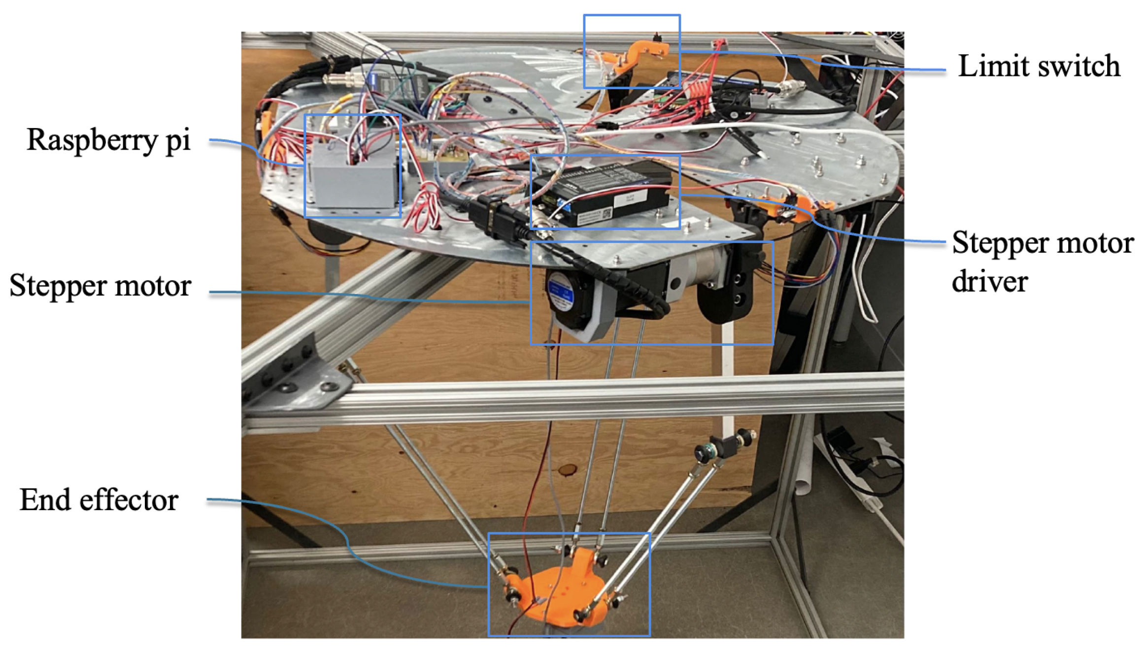
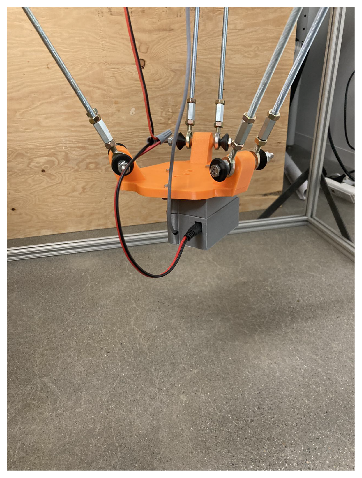
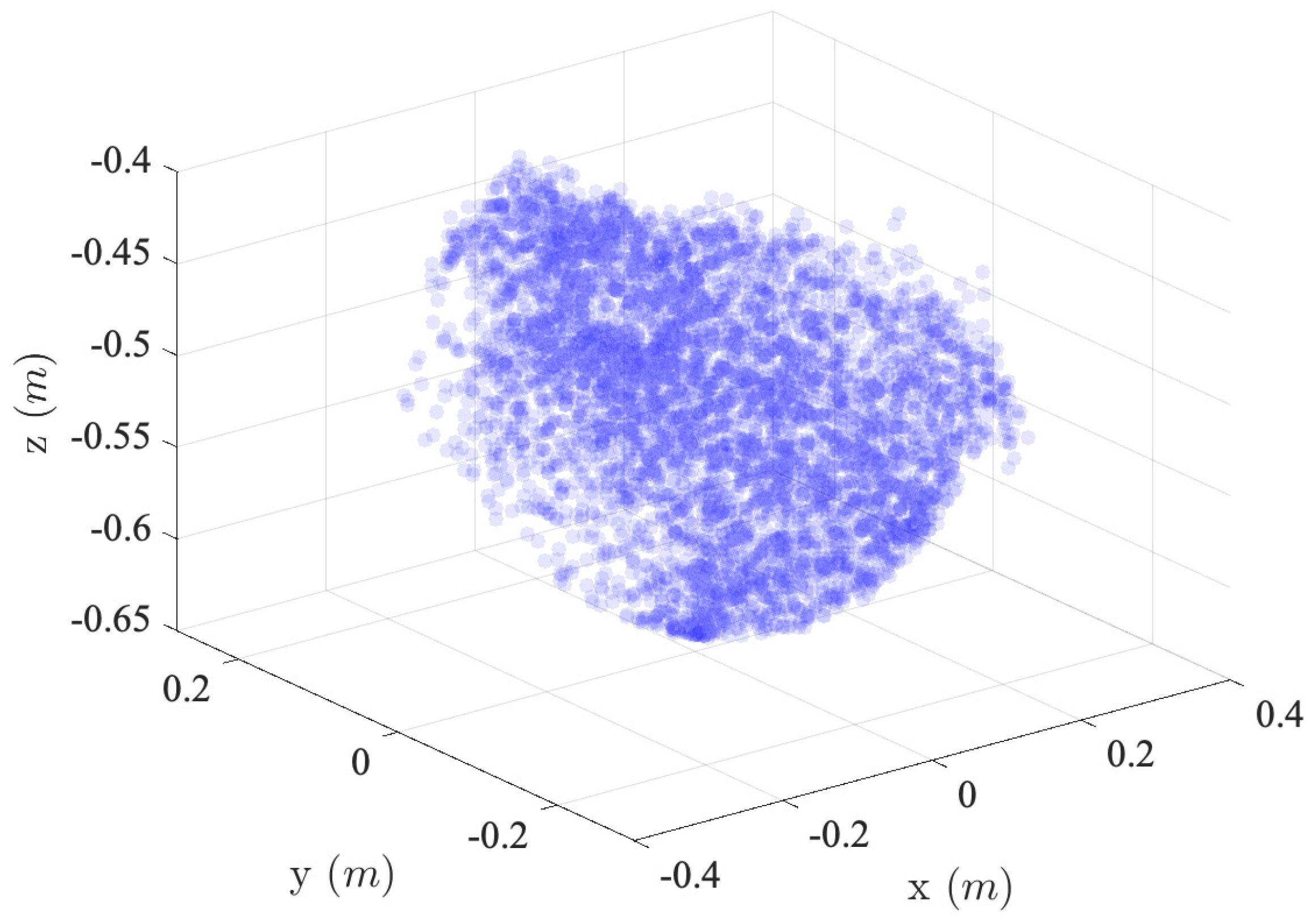
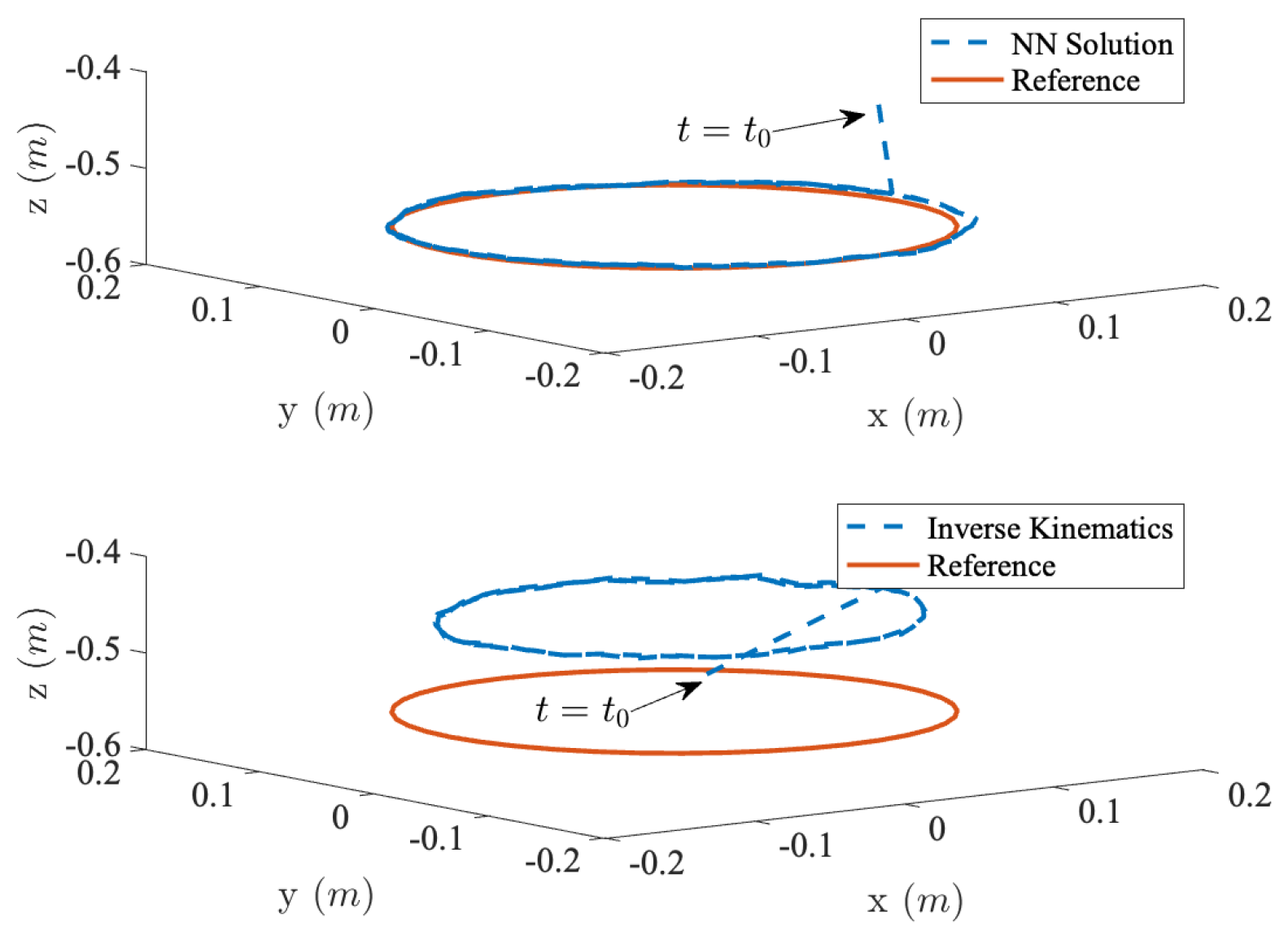
4. Experimental Validations

The trained neural networks are implemented on the hardware of the Delta robot to track different trajectories in an open-loop control, including the circular curve, heart curve, and logarithmic spiral curve. During the operation of the Delta robot, the desired trajectories serve as inputs to the trained neural networks at each time step. We have found that the open-loop tracking control is a remarkable way to directly check the accuracy of the inverse kinematics in an experimental setting.
The trajectory-tracking results of different curves are shown in Figure 7, Figure 8 and Figure 9. The tracking errors with the neural networks and the geometry-based inverse kinematics for different curves are shown in Figure 10, Figure 11, Figure 12, Figure 13, Figure 14 and Figure 15. From these figures, we can see that the neural networks perform better than geometry-based inverse kinematics for different trajectories. Moreover, it is worth noting that the trained neural network model with random data is able to generalize well in different trajectory-tracking applications. The tracking errors of circular curves from neural networks are bounded under 1 cm for the x-, y-, and z-axes, as shown in Figure 11. However, when comparing these results to those depicted in Figure 10, it is observed that the tracking error for the x-axis is bounded under 2 cm, but the tracking errors for the y- and z-axes can reach up to around 4 cm and 110 cm, respectively. This represents an increase of 50% for the x-axis, 75% for the y-axis, and 98% for the z-axis compared to the neural network-based trajectory tracking. For the heart curve, as shown in Figure 12 and Figure 13, the neural network trajectory-tracking performance increases by roughly 50%, 50%, and 80% for the x-, y-, and z-axes, respectively. Similarly, for the logarithmic curve, the neural networks exhibit improved trajectory-tracking performance, with performance increases of around 33% along the x-axis, 40% along the y-axis, and 42.5% along the z-axis, as shown in Figure 14 and Figure 15. All the calculations regarding the performance enhancements are based on the maximum tracking error for the respective axis. Some tracking errors observed with the neural network model may be attributed to factors such as the 5% step accuracy of stepper motors, errors in sensor measurements, and joint backlashes. It should be noted that if a closed-loop control is used, the tracking error can be made as small as possible.
The neural networks are trained on the data collected from a given PWM frequency with step time T P W M = 0.006 s. The neural network model is implemented on the hardware at different operating speeds, including T P W M = 0.002 s, T P W M = 0.006 s, T P W M = 0.01 s, and T P W M = 0.02 s. A summary of the root mean squares of tracking errors e x , e y , and e z , of different trajectories with different operating speeds, is shown in Table 3. To better understand the trajectory tracking in the Cartesian space, the operating speed is also expressed as mm/s, as shown in Table 4. The trajectory-tracking results at the operation speed T P W M = 0.006 s are highlighted to emphasize the performance of the neural networks. From the table, we can see that the neural network model also has the ability to track the trajectory with either a higher or lower operating speed. Compared to the results from the geometry-based inverse kinematics, in general, the neural network model significantly improves the tracking accuracy and has excellent flexibility.

5. Conclusions

A novel data-driven approach is proposed in this study for approximating the inverse kinematics of the Delta robot. We generated random data experimentally to train neural networks for approximating the inverse kinematics with stepper motor angles as inputs. This work, to the best of our knowledge, is the first attempt in the Delta robot studies. The neural networks were validated in different open-loop trajectory-tracking applications at varying operating frequencies. The results show that the use of the proposed neural networks significantly improves the trajectory-tracking performance of the Delta robot when compared to the results obtained from the geometry-based inverse kinematics approach. These findings demonstrate the efficacy of using neural networks as valuable and efficient tools to enhance the control performance of the Delta robot.

Author Contributions

Conceptualization, A.Z. and J.-Q.S.; methodology, A.Z. and J.-Q.S.; software, A.Z.; writing—original draft preparation, A.Z.; writing—review and editing, A.Z., A.T., R.E. and J.-Q.S.; supervision, J.-Q.S. All authors have read and agreed to the published version of the manuscript.

Funding

This research was funded by the AI Research Institutes program supported by NSF and USDA-NIFA under the AI Institute: Agricultural AI for Transforming Workforce and Decision Support (AgAID), award no. 2021-67021-35344. Partial support of the work is from the National Natural Science Foundation of China, grant no. 11972070.

Data Availability Statement

Data sharing is not applicable to this article.

Conflicts of Interest

The authors declare no conflict of interest.

References

  1. Castañeda, L.A.; Luviano-Juárez, A.; Chairez, I. Robust trajectory tracking of a Delta robot through adaptive active disturbance rejection control. IEEE Trans. Control Syst. Technol. 2014, 23, 1387–1398. [Google Scholar] [CrossRef]
  2. Angel, L.; Viola, J. Fractional order PID for tracking control of a parallel robotic manipulator type delta. ISA Trans. 2018, 79, 172–188. [Google Scholar] [CrossRef] [PubMed]
  3. Kuo, Y.L.; Huang, P.Y. Experimental and simulation studies of motion control of a Delta robot using a model-based approach. Int. J. Adv. Robot. Syst. 2017, 14, 1729881417738738. [Google Scholar] [CrossRef]
  4. López, M.; Castillo, E.; García, G.; Bashir, A. Delta robot: Inverse, direct, and intermediate Jacobians. Proc. Inst. Mech. Eng. Part C J. Mech. Eng. Sci. 2006, 220, 103–109. [Google Scholar] [CrossRef]
  5. Zsombor-Murray, P. Descriptive Geometric Kinematic Analysis of Clavel’s “Delta” Robot; Centre of Intelligent Machines, McGill University: Montreal, QC, Canada, 2004; Volume 1. [Google Scholar]
  6. Abed Azad, F.; Ansari Rad, S.; Hairi Yazdi, M.R.; Tale Masouleh, M.; Kalhor, A. Dynamics analysis, offline–online tuning and identification of base inertia parameters for the 3-DOF Delta parallel robot under insufficient excitations. Meccanica 2022, 57, 473–506. [Google Scholar] [CrossRef]
  7. Uzunovic, T.; Golubovic, E.; Baran, E.A.; Sabanovic, A. Configuration space control of a parallel Delta robot with a neural network based inverse kinematics. In Proceedings of the 2013 8th International Conference on Electrical and Electronics Engineering (ELECO), Bursa, Turkey, 28–30 November 2013; pp. 497–501. [Google Scholar]
  8. Almusawi, A.R.; Dülger, L.C.; Kapucu, S. A new artificial neural network approach in solving inverse kinematics of robotic arm. Comput. Intell. Neurosci. 2016, 2016, 5720163. [Google Scholar] [CrossRef] [PubMed]
  9. Zubizarreta, A.; Larrea, M.; Irigoyen, E.; Cabanes, I.; Portillo, E. Real time direct kinematic problem computation of the 3PRS robot using neural networks. Neurocomputing 2018, 271, 104–114. [Google Scholar] [CrossRef]
  10. Tejomurtula, S.; Kak, S. Inverse kinematics in robotics using neural networks. Inf. Sci. 1999, 116, 147–164. [Google Scholar] [CrossRef]
  11. Yang, Y.; Peng, G.; Wang, Y.; Zhang, H. A new solution for inverse kinematics of 7-DOF manipulator based on neural network. In Proceedings of the 2007 IEEE International Conference on Automation and Logistics, Jinan, China, 18–21 August 2007; pp. 1958–1962. [Google Scholar]
  12. Singla, A.; Narayan, J.; Arora, H. Investigating the potential of redundant manipulators in narrow channels. Proc. Inst. Mech. Eng. Part C J. Mech. Eng. Sci. 2021, 235, 3723–3736. [Google Scholar] [CrossRef]
  13. Bai, Y.; Luo, M.; Pang, F. An algorithm for solving robot inverse kinematics based on FOA optimized BP neural network. Appl. Sci. 2021, 11, 7129. [Google Scholar] [CrossRef]
  14. Šegota, S.B.; Anđelić, N.; Mrzljak, V.; Lorencin, I.; Kuric, I.; Car, Z. Utilization of multilayer perceptron for determining the inverse kinematics of an industrial robotic manipulator. Int. J. Adv. Robot. Syst. 2021, 18, 1729881420925283. [Google Scholar] [CrossRef]
  15. Shamseldin, M. Real-time inverse dynamic deep neural network tracking control for Delta robot based on a COVID-19 optimization. J. Robot. Control 2023, 4, 643–649. [Google Scholar]
  16. Boanta, C.; Brişan, C. Estimation of the kinematics and workspace of a robot Using artificial neural networks. Sensors 2022, 22, 8356. [Google Scholar] [CrossRef]
  17. Iklima, Z.; Muthahhar, M.I.; Khan, A.; Zody, A. Self-learning of Delta robot using inverse kinematics and artificial neural networks. Sinergi 2021, 25, 237–244. [Google Scholar] [CrossRef]
  18. Gholami, A.; Homayouni, T.; Ehsani, R.; Sun, J.Q. Inverse kinematic control of a Delta robot using neural networks in real-time. Robotics 2021, 10, 115. [Google Scholar] [CrossRef]
  19. Gholami, A.; Sun, J.Q.; Ehsani, R. Neural networks based optimal tracking control of a Delta robot with unknown dynamics. Int. J. Control Autom. Syst. 2023, 21, 3382–3390. [Google Scholar] [CrossRef]
  20. Kingma, D.P.; Ba, J. Adam: A method for stochastic optimization. arXiv 2014, arXiv:1412.6980. [Google Scholar]
  21. Abadi, M.; Agarwal, A.; Barham, P.; Brevdo, E.; Chen, Z.; Citro, C.; Corrado, G.S.; Davis, A.; Dean, J.; Devin, M.; et al. TensorFlow: Large-Scale Machine Learning on Heterogeneous Systems. arXiv 2016, arXiv:1603.04467. [Google Scholar]
Figure 1. Mechanical structure of the Delta robot.
Robotics 12 00135 g001
Figure 2. Illustration of the inverse kinematics of a Delta robot. (Left) 3D geometry of the Delta robot. (Right) 2D geometry of the Delta robot joints and links.
Robotics 12 00135 g002
Figure 3. Setup of the laser sensor VL53L1X.
Robotics 12 00135 g003
Figure 4. Simulated random joint counts for the Delta robot. (Top) Joint count θ 1 c for stepper motor 1. (Middle) Joint count θ 2 c for stepper motor 2. (Bottom) Joint count θ 3 c for stepper motor 3.
Robotics 12 00135 g004
Figure 5. Random positions of the end effector of the Delta robot in 3D corresponding to the input angles in Figure 4.
Robotics 12 00135 g005
Figure 6. An open-loop control of trajectory tracking for validation of the data-driven inverse kinematics of the Delta robot.
Robotics 12 00135 g006
Figure 7. Circular curve trajectory tracking from the neural network model and the geometry-based inverse kinematics.
Robotics 12 00135 g007
Figure 8. Heart curve trajectory-tracking results from the neural network model and geometry-based inverse kinematics.
Robotics 12 00135 g008
Figure 9. Logarithmic curve trajectory-tracking results from the neural network model and geometry-based inverse kinematics.
Robotics 12 00135 g009
Figure 10. Circular curve trajectory-tracking errors of x-, y-, and z-axes from geometry-based inverse kinematics.
Robotics 12 00135 g010
Figure 11. Circular curve trajectory-tracking errors for x-, y-, and z-axes from the neural network-approximated model.
Robotics 12 00135 g011
Figure 12. Heart curve trajectory-tracking errors for x-, y-, and z-axes from geometry-based inverse kinematics.
Robotics 12 00135 g012
Figure 13. Heart curve trajectory-tracking errors for x-, y-, and z-axes from the neural network-approximated model.
Robotics 12 00135 g013
Figure 14. Logarithmic curve trajectory-tracking errors for x-, y-, and z-axes from geometry-based inverse kinematics.
Robotics 12 00135 g014
Figure 15. Logarithmic curve trajectory-tracking errors for x-, y-, and z-axes from the neural network-approximated model.
Robotics 12 00135 g015
Table 1. Parameters of the Delta robot.
DescriptionNotationValue
Radius of the fixed platformR0.325 m
Radius of the moving platformr0.075 m
Length of the active arm r f 0.5 m
Length of the passive arm r e 0.25 m
Mass of the active arm m f 0.205 kg
Mass of the passive arm m e 0.153 kg
Mass of the end effector m b 0.653 kg
Table 2. Specifications of the components of the Delta robot.
ProductModelSpecification
Stepper Motor
(Stepperonline,
New York, NY, USA)
23HS30-5004D-E1000Motor type: Bipolar
Holding torque: 2.00 N·m
Step accuracy: ± 5 %
Resistance: 0.42  ± 10 %
Inductance: 1.72  ± 20 %
Micro-steppping: 1600 pulses/rev
Stepper Motor Driver
(Stepperonline)
CL57TWeight: 290 g
Input voltage: 24–48 VDC
Pulse input frequency: 0–500 kHz
Min. Pulse width: 1 µS
Planetary Gearbox
(Stepperonline)
PLE23-G10-D8Gear ratio: 10
Efficiency: 94.00%
Max. Permissible Torque: 10 N·m
Moment permissible torque: 20 N·m
Backlash (arcmin): ≤15
Noise ≤ 60 dB
Laser SensorVL53L1X50 Hz ranging frequency
Field-of-View: 27
Ranging error (mm): ± 25
I 2 C interface
Raspberry Pi 4Model B64-bit Cortex-A72 processor
4 GB LPDDR4 RAM
Table 3. A summary of the trajectory-tracking errors of the Delta robot with different operating speeds.
AlgorithmCurve T PWM RMS e x RMS e y RMS e z
CircleNeural networks0.0020.00380.00560.0112
0.0060.00450.00570.0112
0.010.00590.00640.0111
0.020.00410.00470.0115
Inverse Kinematics0.0060.01220.02380.1015
Heart CurveNeural networks0.0020.0040.00670.0128
0.0060.0040.00690.0128
0.010.0040.00680.0126
0.020.00720.00810.0132
Inverse Kinematics0.0060.01480.01250.0447
Logarithmic SpiralNeural networks0.0020.00860.00410.0124
0.0060.00970.00680.0068
0.010.01830.01010.0069
0.020.01250.00790.0100
Inverse Kinematics0.0060.01490.00870.0271
Table 4. Operating speed of the Delta robot in mm/s.
T PWM  (s)mm/s
0.00246.5250
0.00615.5083
0.019.3050
0.024.66525
0.0060.0122
Disclaimer/Publisher’s Note: The statements, opinions and data contained in all publications are solely those of the individual author(s) and contributor(s) and not of MDPI and/or the editor(s). MDPI and/or the editor(s) disclaim responsibility for any injury to people or property resulting from any ideas, methods, instructions or products referred to in the content.

