Abstract
The control of deformable linear objects (DLOs) such as cables presents a significant challenge for robotic systems due to their unpredictable behavior during manipulation. This paper introduces a novel approach for cable shape control using dual robotic arms on a two–dimensional plane. A discrete point model is utilized for the cable, and a path generation algorithm is developed to define intermediate cable shapes, facilitating the transformation of the cable into the desired profile through a formulated optimization problem. The problem aims to minimize the discrepancy between the cable configuration and the targeted shape to ensure an accurate and stable deformation process. Moreover, a cable dynamic model is developed in which the manipulation approach is validated using this model. Additionally, the approach is tested in a simulation environment in which a framework of two manipulators grasps a cable. The results demonstrate the feasibility and accuracy of the proposed method, offering a promising direction for robotic manipulation of cables.
1. Introduction
Cables, wires, and other deformable linear objects (DLOs) are integral to a wide range of everyday applications, encompassing tasks such as wiring in the automotive industry [1,2,3], belt assembly [4], and surgical suturing [5,6]. However, robotizing the DLOs–related tasks is still an open challenge in the robotics community due to the inherent complexity and the multitude of ways in which DLOs can deform [7]. Thus, the manipulation of these objects has gained a significant amount of interest, and many researchers have proposed approaches to the handling of DLOs either by stationary single–manipulator systems [3], stationary multi–manipulator systems [8], or mobile robots [9]. A significant domain of DLO manipulation is the shape control of cables and other DLOs, which are presented in various practical applications. For example, in industry, two robots bend a long cable harness to fit into the car chassis, and, in minimally invasive surgery in medicine, where tiny cables are used within flexible endoscopes or surgical instruments, a robotic system could be utilized to shape the cable precisely to navigate through the body.
Recent research has made significant strides in this shape control domain, with approaches ranging from model–based methodologies to innovative learning–based strategies. Herein, we discuss the current state–of–the–art techniques, highlighting key contributions and identifying the limitations and advancements that shape this field of study. Li et al. [10] proposed a model–based methodology for guiding a cable by a robotic manipulator. Their method models the cable as a set of discrete points, which are manipulated sequentially toward predetermined reference points. Based on the discrete elastic rod, Lv et al. developed a dynamic control scheme, facilitating the shape control of cables with a singular manipulator [11] and then with coordinated dual manipulators [12]. The main limitations of this model–based approach are how accurately the DLO is modeled and the complexity of the model, which increases the computation cost. Further advancements in the field have seen the adoption of online estimation techniques, where a slight change in a DLO is proportionate to a small robot displacement, inferred by a locally derived Jacobian matrix [13,14,15]. This matrix is refined continually through data collected during the manipulation task. A notable development by Yu et al. [16] integrates offline data–driven Jacobian estimation with online neural network adaptations, thereby enhancing the adaptability of shape control schemes. Based on DLO kinematics and the diminishing rigidity property, some works have defined an approximate model mapping between the robot end–effectors and the DLO [17,18,19]. Although these approaches have real–time performances, they are suitable only for local and simple deformation tasks. Nair et al. [20], Tang et al. [21], and Yan et al. [22] pioneered learning–based methodologies for DLO manipulation. These methodologies enable robots to learn from observing how a human expert manipulates a DLO and, subsequently, attempts to replicate these actions to achieve a similar manipulation of the DLO. Additionally, the use of reinforcement learning (RL) represents a significant advancement in robotic learning capabilities. In RL, a robot is trained to perform tasks by following a policy shaped by rewards received for successful interactions with its environment. This kind of learning is not just about imitation but about understanding the consequences of actions and adapting to achieve specific goals. Laezza et al. [23] and Zakaria et al. [24] have made substantial contributions in this area by developing RL policies that guide robots to deform these objects effectively. Although these learning and RL approaches show solid performances, they require a significant amount of resources and data. The shape perception of DLOs is a crucial stack in shape control tasks to ensure accurate tracking of the object. Currently, sensor–based shape perception studies offer a promising direction for addressing challenges in this domain and present practical applications [25,26,27].
The simulation and modeling of DLOs play a pivotal role in various technological fields, including virtual reality, machine learning, control and manipulation process validation, and identification of the physical parameters of real DLOs. Unlike their rigid counterparts, DLOs pose a unique challenge. This challenge lies in accurately obtaining physical properties, which can differ significantly from one object to another, thereby making theoretical predictions quite complex. To address this modeling challenge, various techniques have been developed and refined. For instance, the mass–spring model, as discussed by Lv et al. [28], captures the interplay between mass and elasticity. The multi–body model proposed by Servin et al. [29] considers the DLO to be a series of interconnected rigid bodies, while the position–based dynamics model presented by Xu et al. [30] focuses on the real–time dynamics of DLOs. The elastic rod model by Linn et al. [31] provides insights into the behavior of a flexible cable, and the dynamic spline model developed by Valentini et al. [32] offers a way to simulate DLOs using a series of connected splines that approximates their dynamic properties. Some researchers utilize the finite element analysis to model cables when a high accuracy of the cable behavior is required [33]. The comprehensive reviews by Yin et al. [34] and Lv et al. [35] offer detailed overviews of these models. These reviews not only cover the modeling of linear DLOs but also explore the broader spectrum of deformable objects, providing invaluable resources for researchers and practitioners in the field. Through these collective efforts, there is a clearer understanding of how DLOs behave, which is essential for advancing applications that rely on the precise manipulation and control of these complex objects.
In this paper, first, we tackle the intricate challenge of planar shape control of cables with dual manipulators. We introduce an innovative manipulation planning framework that plans the cable’s transformation from its initial state to a desired final state. A central element of our method is an algorithm engineered to create intermediate profiles that articulate the path for the cable. We address the control challenge through a novel optimization problem. Figure 1 represents the structure of the developed approach. Then, we introduce a cable mass–spring model used in the approach validation. The efficacy of our approach is rigorously tested through a series of simulations demonstrating its potential in various shapes. The main contributions of this paper are:

Figure 1.
Overview of the proposed cable shape control methodology. In the Cable sampling, the cable (black) and desired shape (green) each is represented as a set of N points. The Cable path planning generates the path as a set of intermediate profiles (Cyan). The Robots motion planning generates the control signal to the robots to guide the cable along the intermediate profiles toward the desired shape.
- We propose an innovative approach for controlling the shape of cables with dual robotic arms. This approach handles the large deformation tasks by decomposing the task into multiple simple ones.
- We define the robot’s motion planning as an optimization problem to minimize the shape error between the cable configuration and the targeted shape, ensuring accurate and stable deformation.
- We introduce a cable dynamic model, which is used for validating the manipulation approach.
- The approach is validated in two simulation environments proving its potential for applications that require precise control of cables and other DLOs.
The structure of the remainder of the paper is outlined as follows: The forthcoming section formulates the problem we aim to address and establishes the notations used throughout the paper. In Section 3, we propose a new manipulation methodology. Section 4 describes the mass–spring model of cables. The simulation studies’ outcomes are thoroughly examined in Section 5. In Section 6, we highlight the approach´s strengths, limitations, and areas for improvement. Finally, we conclude and propose directions for future research in Section 7.
2. Problem Formulation
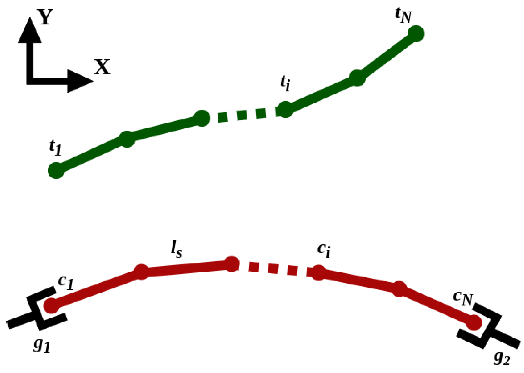
Consider two robotic arms rigidly grasping a cable at its two ends. The robots cooperatively manipulate the cable on a 2D plane to deform it from an initial to a desired shape. The cable and the desired shape are each represented by N points uniformly distributed along the cable length, where the distance between each two adjacent points is the constant . Figure 2 shows a schematic of a cable grasped by two end–effectors along with the desired shape. Let and be arrays of cable point coordinates and the desired shape point coordinates, respectively; where and , for . The configurations of the robots’ end–effectors are defined by the vector ; where .
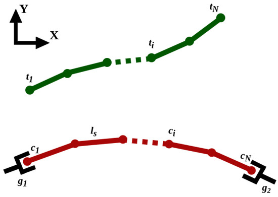
Figure 2.
A schematic illustration of a cable (red) grasped by two end–effectors and the desired shapes (green).
This work addresses the task of cable shape control. The key problem of this task is to formulate the behavior of the robots to guide the cable toward its desired shape. In this regard, we propose a new approach to generating a path: the robots’ end–effectors guide the cable through toward the desired shape, and the end–effectors’ configurations are updated based on an optimization problem to minimize the deflection between the cable shape and the desired shape. Differing from the previous work in the literature, we aim to introduce a cable manipulation approach that does not require prior knowledge of the cable’s dynamic parameters, similar to the model–based approaches; it is resource– and computationally efficient compared to the RL and learning–based approaches and suitable for complex deformation tasks by decomposing these tasks into a set of simple sequential ones, outperforming the Jacobian–based approaches, which also do not need to collect data and online tuning.
3. Methodology
3.1. Path Generation
One of the main challenges during cable manipulation is overstretching and unpredictable cable deformation, especially in large deformation tasks in which there is the potential for large displacement. We tackle these issues by breaking down the deformation task into several stages as intermediate profiles, where the cable deforms gradually towards its desired shape. These profiles form the path through which the cable will move.
To generate these profiles, we compute the differential vector , which captures the positional difference between the target configuration and the initial shape . Within this vector, the value stands out as the maximum distance and the maximum absolute value in . Using this, we introduce , which is a user–defined scalar representing the maximum allowable step size between two stages. From this, the total number of stages in the deformation process is given by:
Then, we obtain the step-size of each cable point, , as follows:
Considering that the cable at stage is the desired shape of , the intermediate profiles are computed backwards, where , for to 1. For each , we compute the angle between each two adjacent points, , where is given by:
The algorithm checks the distance between every two adjacent points. If this distance diverges from the expected segment length , the cable point is updated as follows:
Algorithm 1 illustrates the proposed path generation approach. The algorithm outputs a series of feasible intermediate shapes, allowing smooth manipulation of the cable from its starting shape to the target shape sequentially while consistently adhering to its length constraints.
| Algorithm 1 Cable Path Generation Algorithm |
|
3.2. Robot Motion Planning
Once the path of the cable has been generated, the end–effectors’ configurations are controlled accordingly to guide the cable along the path. The control problem is formulated as the following optimization problem:
where the first term of the objective function represents the error between the cable shape and the desired one, and the second term is defined to constrain the cable and avoid over-stretching and compression during the manipulation. ; is a diagonal positive definite matrix; and is a positive scalar. The constraint is to limit the displacement to maintain the quasi-static manipulation condition, where is a vector of the linear and angular maximum velocities. Based on the defined objective function, the control points will be updated to minimize the error between the DLO shape and the desired shape while holding the length constraint.
The end–effectors’ configurations and are mapped into the objective function by substituting the first and last two cable points as follows:
Thus, the motion planning method will generate the required end–effectors’ configurations that minimize the cable shape error sequentially to the final desired shape. We consider the mean error , the error standard deviation , and the maximum error as the metrics to evaluate the approach´s performance.
where is the element-wise absolute value.
In the next section, we introduce a cable dynamic model that is used to test and evaluate the approach in the simulation.
4. Cable Mass–Spring Model
The mass–spring model is a practical and easily understandable physical modeling of deformable objects. It is also efficient when it comes to computation and resource costs [35]. Due to these advantages, this model finds widespread use in simulating deformable objects, such as cables [28], clothing [36], and tissue [37].
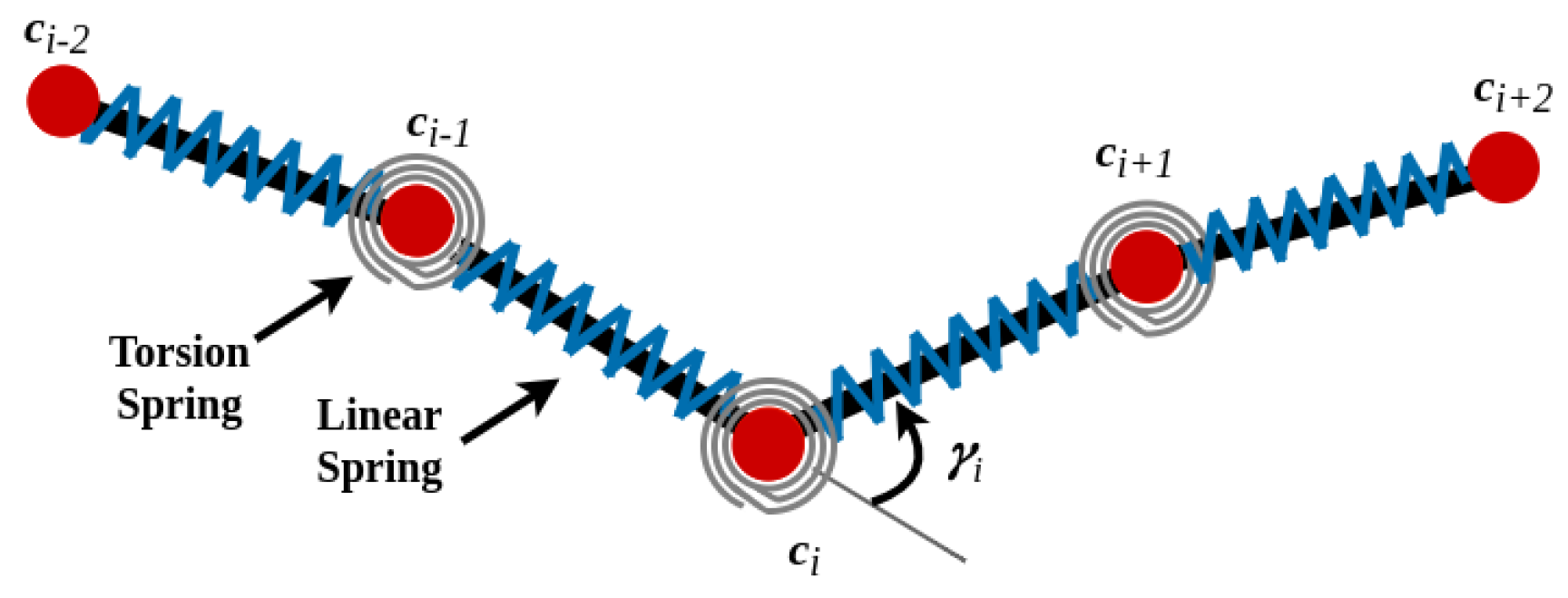
In this study, we utilize the mass–spring model to assess our manipulation approach. In this model, the cable is broken down into a series of N mass points. The positions of these mass points determine the shape of the cable, while they are connected by N-1 stiff linear springs to maintain the cable’s length. Additionally, the model incorporates N-2 torsion springs located at the mass points (excluding the endpoints), which account for the cable’s elastic bending behavior. The springs are assumed to be massless. Figure 3 depicts the cable model, including the springs.
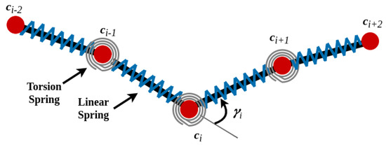
Figure 3.
Schematic representation of the cable mass–spring model used in the study.
The motion of the mass points is expressed by Newton’s second law:
where and are the first and second derivatives of the mass points, respectively; is a diagonal matrix of the mass points; is the length preservation force exerted by the linear springs; is the internal bending force exerted by the torsion springs; is the damping forces’ vector, preventing excessive vibration of the mass points.
Equation (11) can be formulated as two coupled equations:
where and
To handle the time step issue resulting from the stiff linear and torsion springs in the simulation, we use the backward Euler method for a time step h:
Taking the first-order Taylor series of :
where and are the position and velocity changes from a time step t to , respectively:
Substituting Equation (14) into (13), the model equation can be written in the following linear form:
where
and
Then, the new states of the cable points are obtained as follows:
The following subsections discuss the forces’ formulations and their derivatives.
4.1. Length Preservation Force
The length preservation force, , is derived from the potential energy of the linear springs, which is given by:
where is the stiffness parameter of the linear spring.
4.2. Bending Force
Similar to length preservation forces, bending forces are derived from the potential energy of torsion springs. The potential energy of the torsion spring is:
where is the stiffness parameter of the torsion spring; is the angle between two links connected to the point , shown in Figure 3; and:
The bending force acting on the point is given as the first derivative of Equation (25):
where
and
Then, we compute the partial derivatives of Equation (27) for all points:
4.3. Damping Force
The damping force is derived as the time derivative of the linear spring force:
where is the damping coefficient.
Then, we compute the partial derivatives of Equation (31) with respect to the position and velocities:
Once we calculate the forces and their derivatives, we substitute their values into Equation (17) and obtain using the conjugate gradient (CG) method. Then, the cable points’ states are obtained accordingly using Equations (20) and (21). More details on the force derivatives are discussed in [28,38].
5. Results
To evaluate the proposed algorithm, various simulations are conducted based on the cable model discussed in Section 4. The simulations are carried out in MATLAB running on the Windows 10 operating system on a computer equipped with an Intel Core i7–10510U CPU that runs at 1.8 GHz and 16 GB of RAM.
The desired shape is discretized based on the cable parameters N and L. The number of cable points N and the segment length are determined by the cable total length L and the cable harness [28]. In our case, we obtained a satisfactory performance for . Table 1 presents the parameter values used in the simulation. The linear and torsion springs’ stiffness parameters are computed by the formulas proposed in [28] as:
where Y is Young’s modulus and d is the cable diameter.

Table 1.
Simulation parameters.
Remark: In real–life experiments, the cable can be segmented into a set of points either by adding marks on the cable [16] or by virtually generating these points [19].
Two simulation studies are conducted. The first study compares the performance of the proposed approach for two setups:
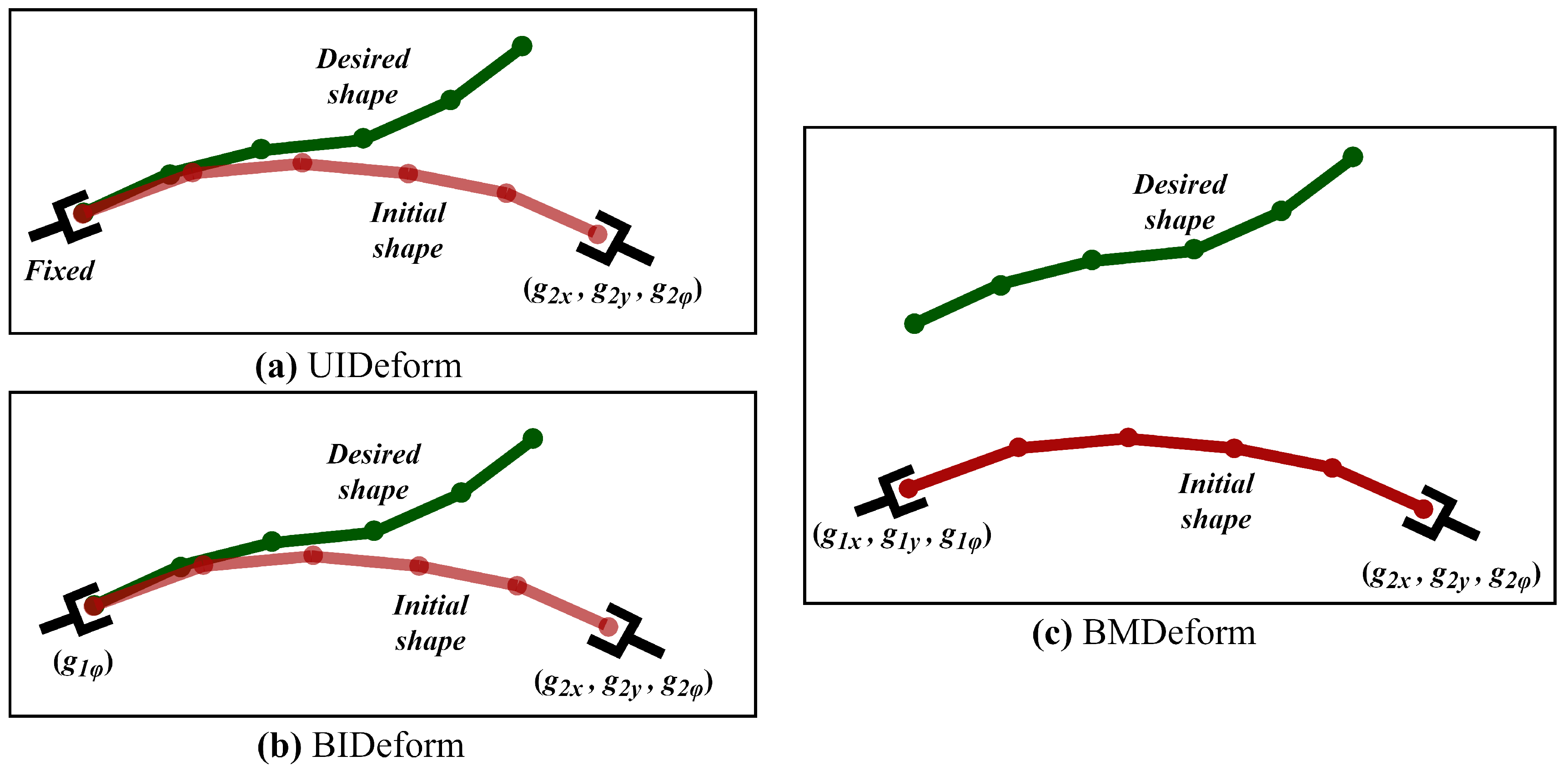
- Unilateral in–place deformation (UIDeform), where one cable end is fixed, and the deformation is carried out by one robot grasping the other cable end.
- Bilateral in–place deformation (BIDeform), where the cable is fixed at one end and being deformed by two robot end–effectors.
This type of deformation can be found in quality control for electronic components, where robots are used to test the flexibility and durability of cables. One end of the cable is rigidly clamped, and the robot grips the other end of the cable with a specialized end effector designed to mimic the actions of plugging and unplugging or bending that the cable might experience in actual use. The robot then moves in predetermined patterns that simulate the real–world bending that the cable might undergo during its lifecycle. The second simulation set studies the performance of the approach where the cable initially is far from the desired shape, and the robots should deform and translate it. This emulates the cable assembly task in the automotive industry where two robots deform a cable harness to place it into the chassis of a car. We refer to the setup of this study as Bilateral manipulation and deformation (BMDeform). Figure 4 illustrates these setups and the degree of freedom of each robot for each setup.
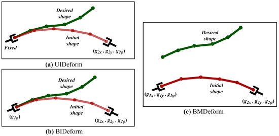
Figure 4.
The cable’s initial shape (red) and desired shape (green) in the suggested setups for testing the proposed approach. (a) UIDeform: the first end–effector is completely fixed, (b) BIDeform: the first end–effector can only rotate; in both UIDeform and BIDeform the second end–effector has 3DOF (2 translations and a rotation). (c) BMDeform: both end–effectors have 3DOF (2 translations and a rotation).
5.1. UIDeform vs. BIDeform
In this study, we validate the co–manipulation setup compared to the single–robot manipulation for the same conditions. The cable is fixed at one end, and it is deformed to the desired shape by one manipulator in UIDeform and by dual arms cooperatively working together in BIDeform.
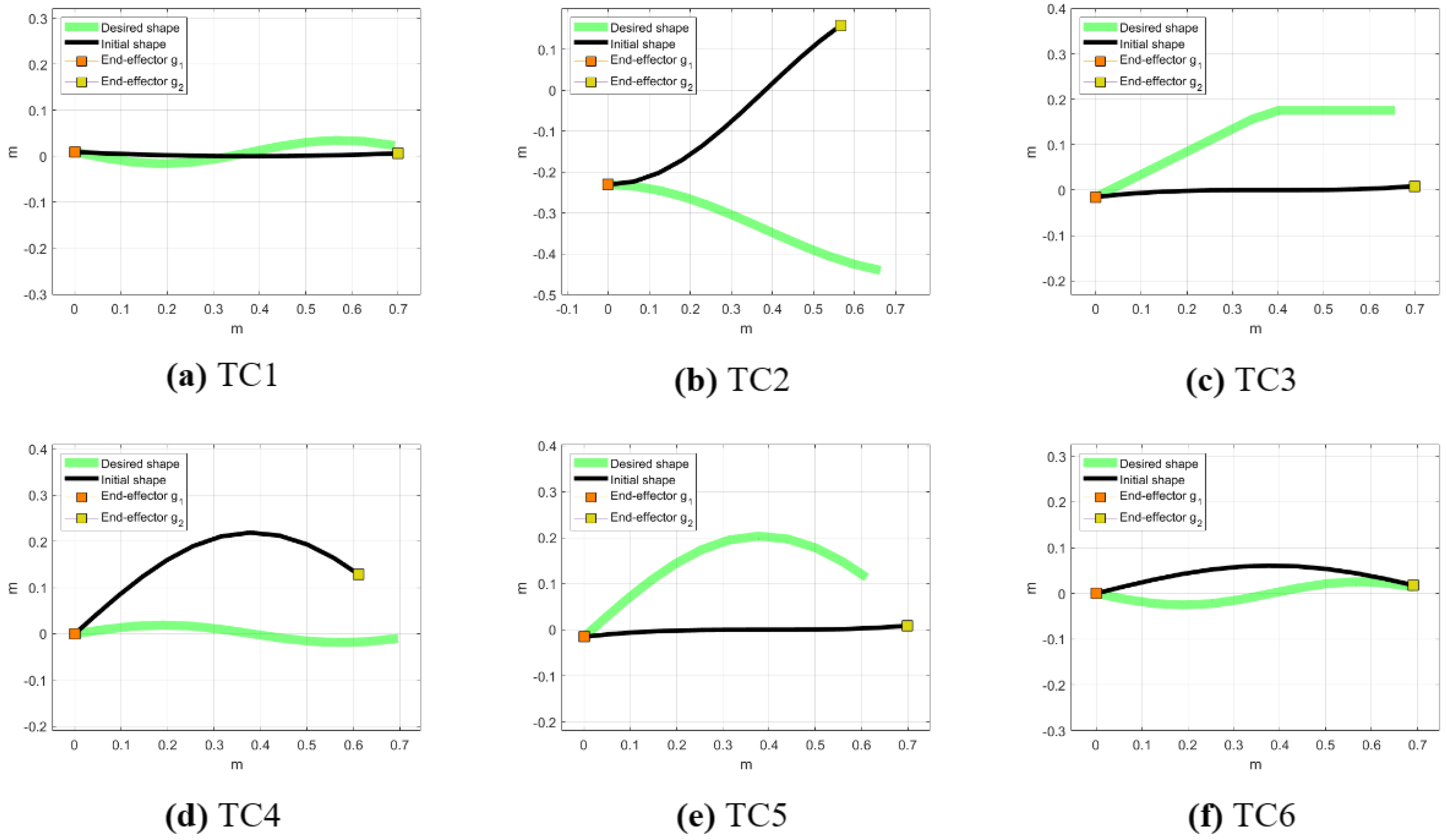
Figure 5 shows six Test Cases (TCs) with different levels of complexity. In TC1, Figure 5a, the initial and desired shapes slightly diverge from each other, representing a straightforward task. TC2, Figure 5b, presents a more challenging scenario in which the initial shape has a relatively high negative slope compared to the desired positive slope. In TC3, Figure 5c, the initial and desired shapes are distinctly different: the initial shape has no vertical displacement, while the desired shape has a positive slope until about the midpoint of the X–axis, after which it becomes horizontal. TC4, Figure 5d, introduces a more complex scenario in which the second half of the cable, the part of the cable closer to the end–effector , is downwardly concave in the initial shape and upwardly in the desired shape. TC5, Figure 5e, shows a gentle, smooth curve in the desired shape with a slight initial deviation at the start, suggesting a less complex control task for the system. Finally, TC6, Figure 5f, resembles TC4, however, the concavity of the initial and desired shapes differs in the first half of the cable, which is the part of the cable that is closer to the end–effector .
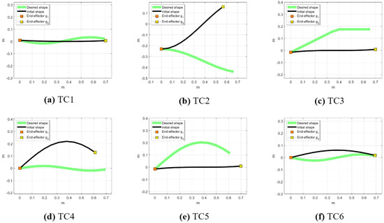
Figure 5.
Cable initial and desired shapes of the Test Cases of UIDeform and BIDeform setups. (a) The initial and desired shapes are slightly different, representing an easy task. (b) The initial shape has a significant negative slope, contrasting with the desired positive slope. (c) Features distinctly different initial and desired shapes; the initial shape is flat, while the desired shape slopes positively until the midpoint and then becomes horizontal. (d) A complex scenario in which the latter half of the cable (closer to end–effector ) is initially downwardly concave but desired to be upwardly concave. (e) A gentle control task, a smooth curve in the desired shape with a minor initial deviation. (f) Similar to TC4 but with the concavity differences in the first half of the cable (closer to end–effector ).
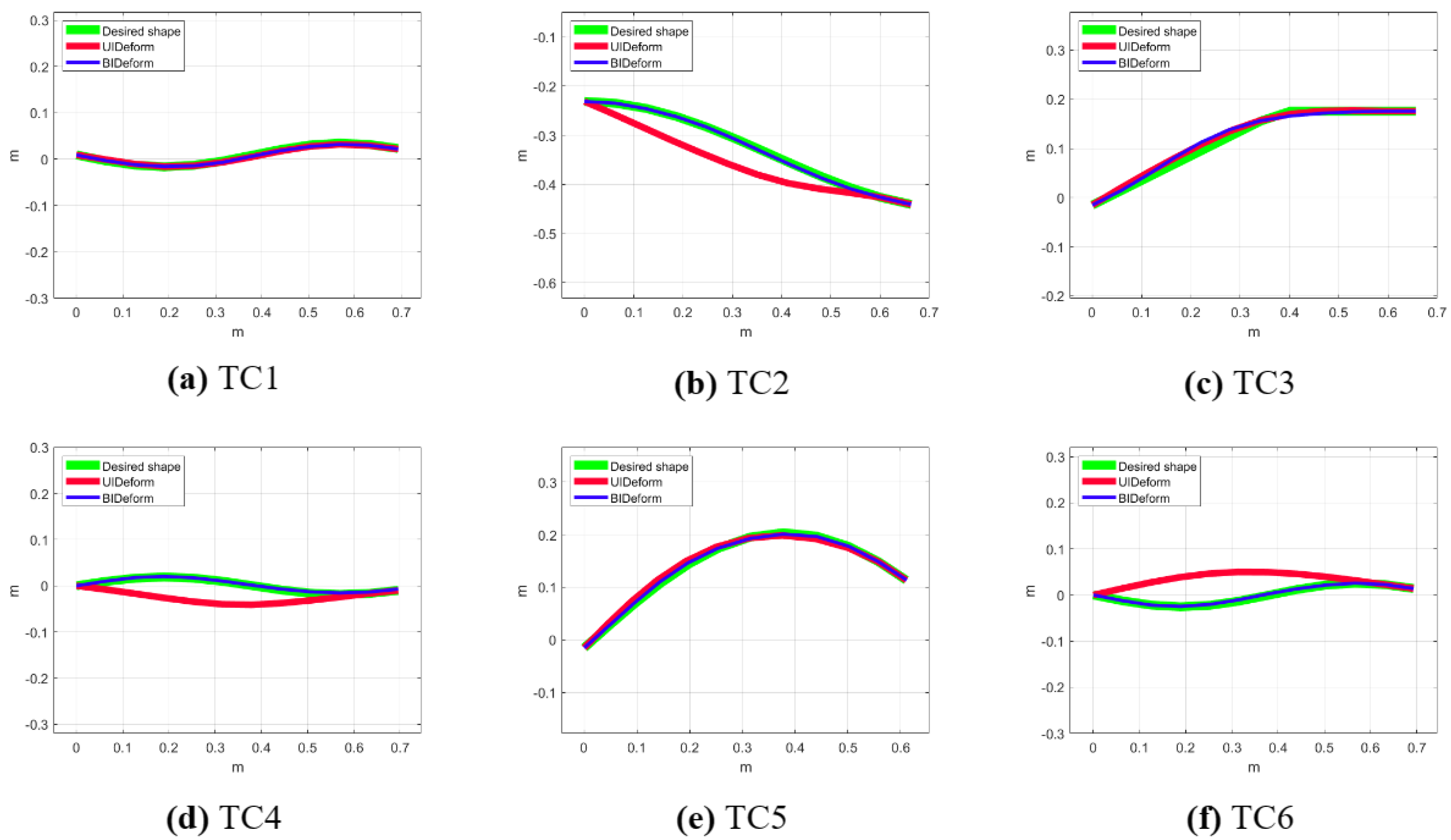
Figure 6 depicts the final cable shapes after the deformation tasks in both the UIDeform and BIDeform setups across the considered Test Cases. For the simple Test Cases (TC1, TC3, and TC5), both setups achieve the task with minimal deviation from the desired shape. This indicates that, for tasks involving more linear shapes, the efficiency of the approach in both single– and dual–robot systems is comparable.
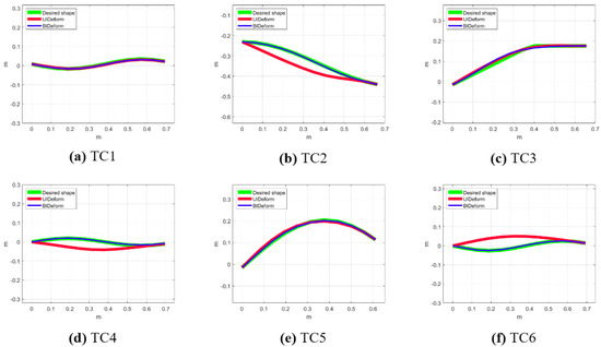
Figure 6.
The final cable shapes after deformation tasks in UIDeform and BIDeform setups.
Conversely, in the more complex Test Cases (TC2, TC4, and TC6), the UIDeform setup, which uses a single robot, fails to accomplish the desired shapes, highlighting its limitations in handling complex deformations. In contrast, the BIDeform setup, which utilizes a dual–robot system, shows a superior performance and successfully shapes the cable into the desired configurations. This demonstrates the dual–robot system’s enhanced capability to control the deformation of the cable, likely benefiting from coordinated manipulation and increased control points that allow for more complex shape executions.
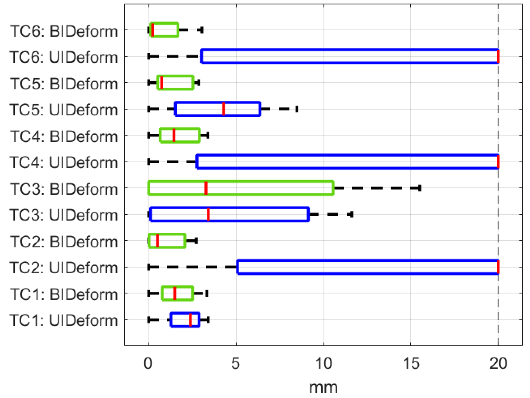
The approach efficiency for both the UIDeform and BIDeform setups is illustrated in Figure 7 and Table 2, represented by the error between the cable’s final shape and desired shape. UIDeform and BIDeform successfully finished TC1, TC3, and TC5 with almost the same error values. However, for TC2, TC4, and TC6, while UIDeform dramatically failed to fit the cable into the desired shape and terminated with high error values, BIDeform showed a high position accuracy and achieved these tasks similarly to the others.
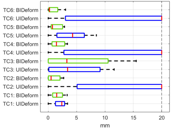
Figure 7.
The approach efficiency represented by error box plots of each Test Case in UIDeform vs. BIDeform setups.

Table 2.
Comparison between the efficiency approach in UIDeform and BIDeform setups.
Additionally, Figure 8 shows how the shape error converges during the task over time. It compares the simulation times of UIDeform and BIDeform, excluding the failed cases of UIDeform. It can be seen that although the approach handled Test Case 1 at the same time for both systems, the UIDeform system needed more time than BIDeform as the task complexity increased.

Figure 8.
The error convergence during deformation for (a–c) in UIDeform and BIDeform setups.
Comparing the two setups, BIDeform offers a more reliable performance in cable shape manipulation, particularly in tasks that demand high fidelity to the desired shape. The ability of BIDeform to more accurately align with the desired outcomes across all Test Cases suggests potential advantages in employing a dual–robot system for complex shape manipulation tasks in industrial or robotic applications where precision is paramount.
5.2. BMDeform
Herein, the approach is validated for the cases where the initial shape is relatively far from the desired shape and requires more manipulation to fit the cable into the desired shape.
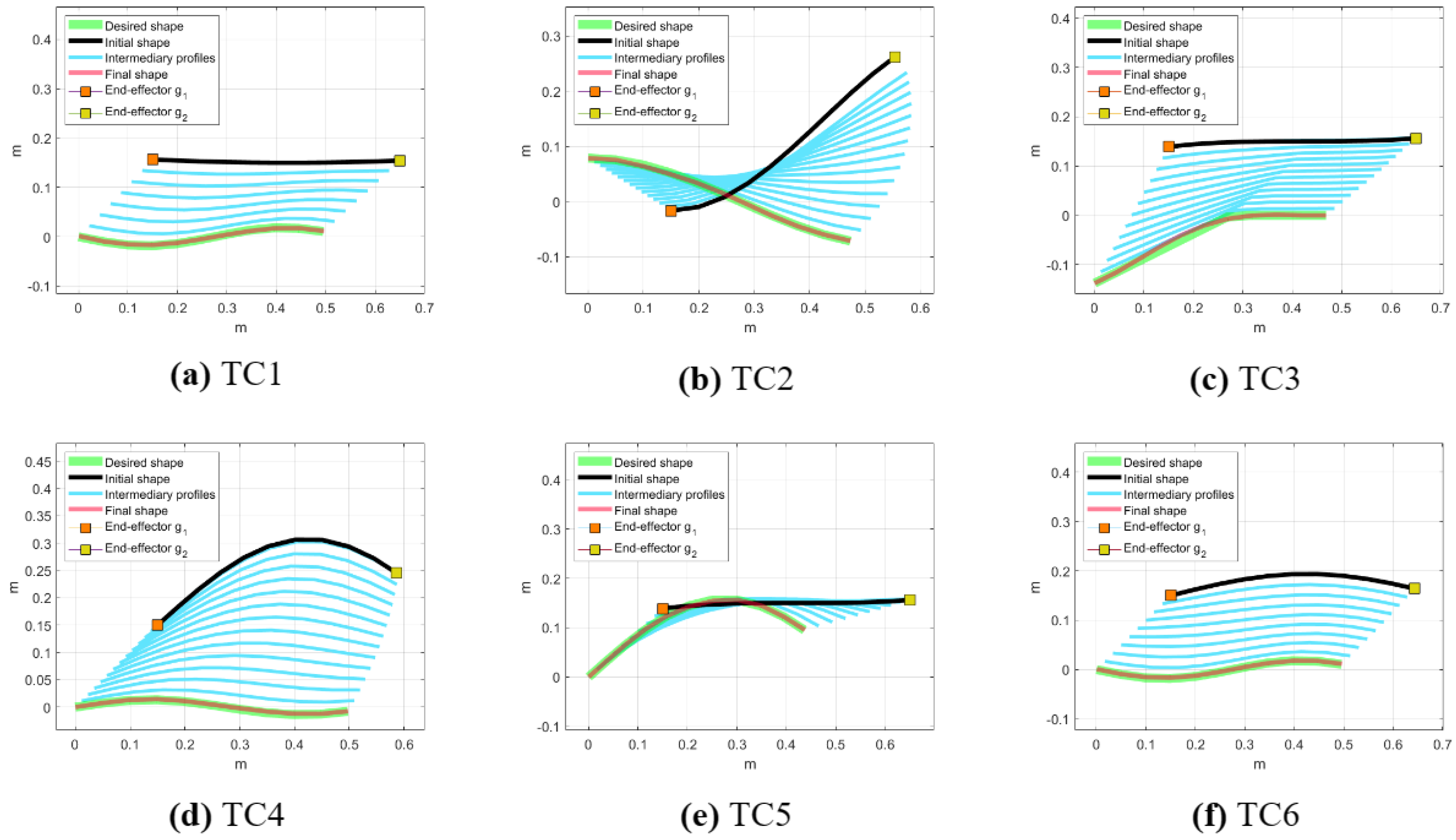
Figure 9 shows the initial and final shapes of the cable, along with the desired and intermediate profiles for each test case in the BMDeform setup. The figure highlights the path generation algorithm’s effectiveness in producing intermediate profiles that progressively guide the cable from its initial state to the target configuration. This step–by–step deformation process ensures local conditions are met and instability is avoided. It can be observed that the approach successfully achieved the task and the cable’s final shape fits the desired shape for all Test Cases. The systematic progression underscores the approach’s precision in handling complex manipulations, adapting the cable’s shape incrementally to achieve the final desired form.
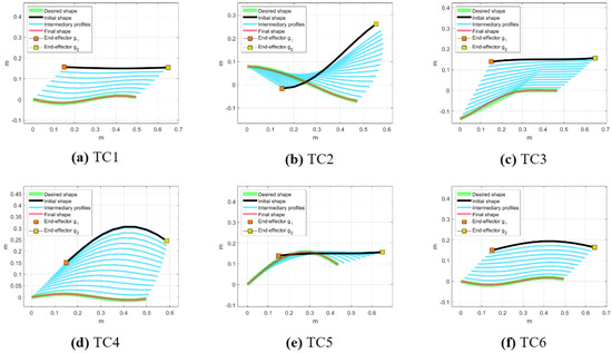
Figure 9.
Cable initial and final shapes of the Test Cases alongside desired and intermediate shapes in BMDeform setup.
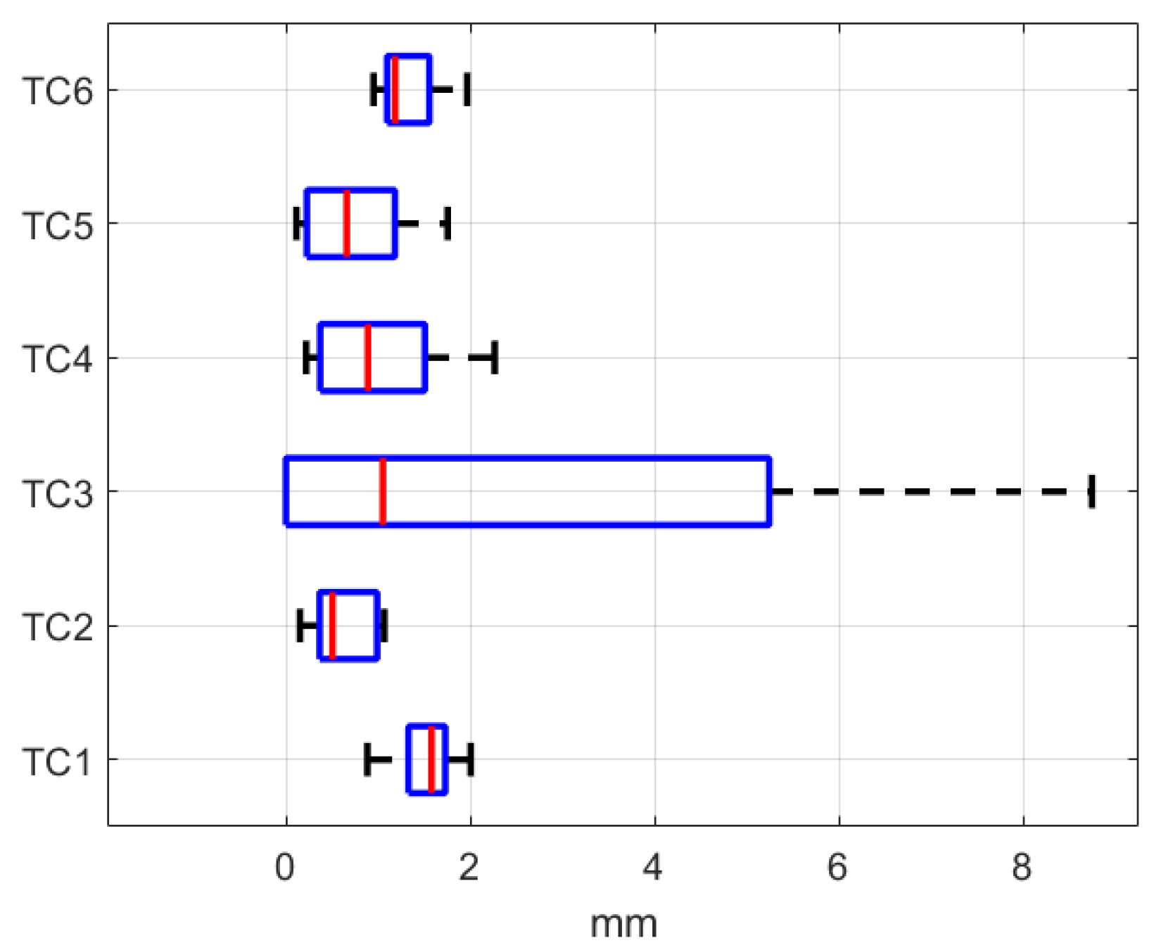
The box plots in Figure 10 and Table 3 illustrate the shape error for each Test Case in the BMDeform setup. TC3 stands out with the highest maximum error and wider error range, due to the coarse inflection in the desired shape, which leads to a higher difficulty level in shape manipulation. The other Test Cases, particularly TC1 and TC5, exhibit tight error distributions, reflecting a high degree of precision and reliability in achieving the desired cable configurations. These results suggest the method’s robustness and potential for precise automated tasks in various applications.
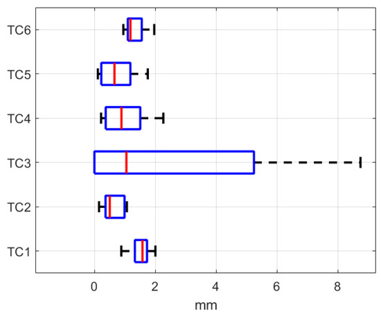
Figure 10.
The approach efficiency represented by error box plots of each test case in BMDeform setups.

Table 3.
The efficiency of the approach in BMDeform setup.
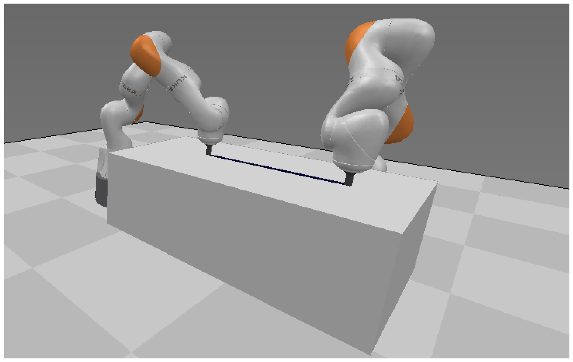
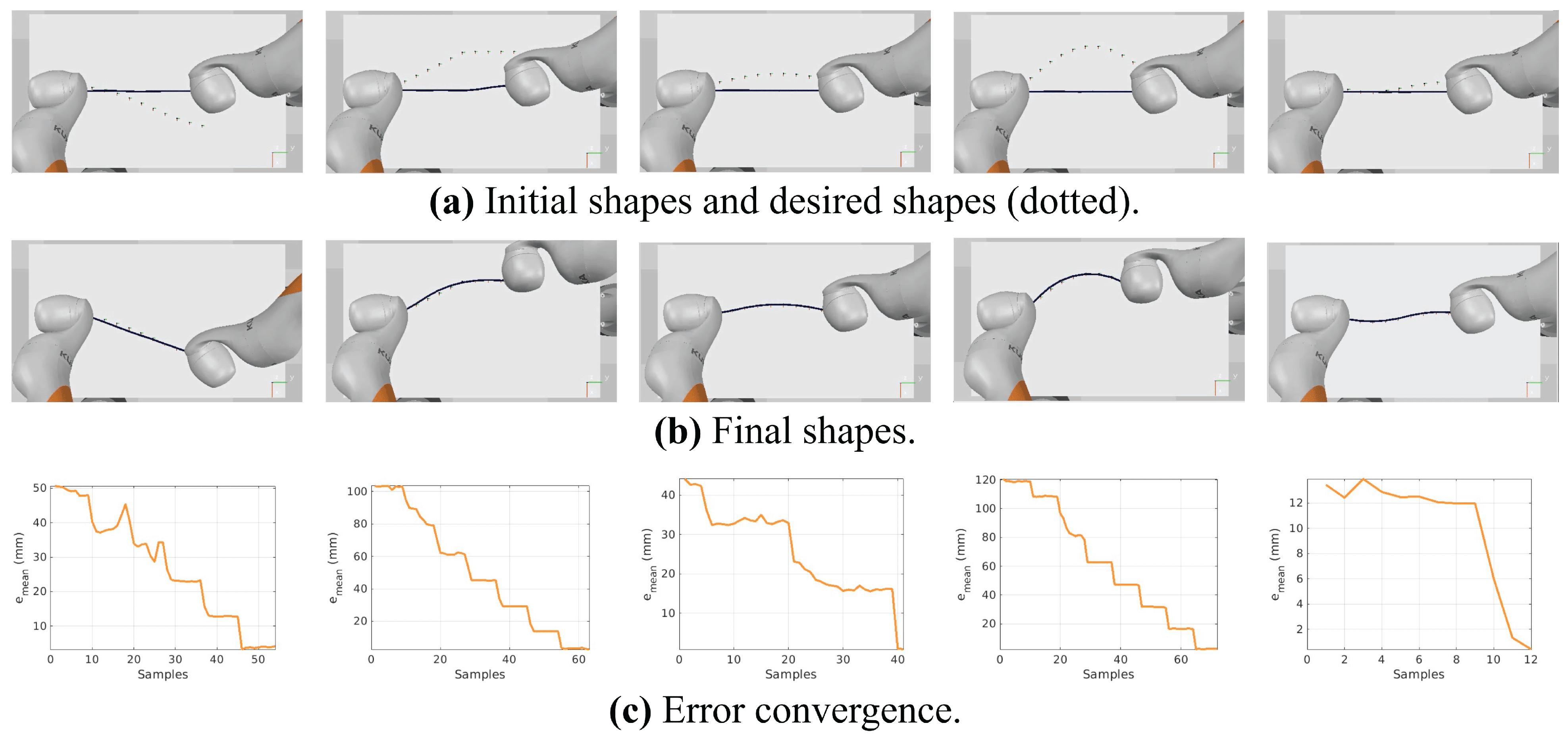
The approach is further evaluated in a setup built in CoppeliaSim (V–rep) [39]. A framework is developed in which a cable is rigidly attached to two Kuka iiwa manipulators’ end–effectors, as shown in Figure 11 and the Supplementary Video. Differing from the previous simulation studies, the cable in CoppeliaSim is modeled as a multi–body model in which a set of rigid links are connected by spherical joints. Several experiments are carried out in this framework. Figure 12 depicts the initial and final shapes and the error convergence of some experiments. It can be seen that the robots successfully achieved the tasks and deformed the cable accurately.
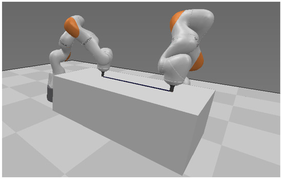
Figure 11.
Experimental setup in CoppeliaSim for cable manipulation trials.
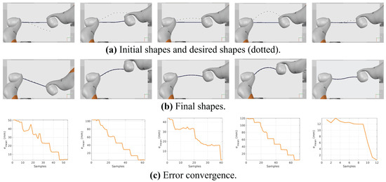
Figure 12.
Results of experiments conducted in the CoppeliaSim simulation environment.
To summarize, the approach has been evaluated in different Test Cases with different complexity levels for both single–arm and dual–arm robotic systems. The outcomes show the efficiency and accuracy of the developed method to control a dual–arm system for handling cable shape control tasks. Moreover, it can control a single robot to accomplish simple shape control tasks.
6. Discussion
In this paper, we present a novel methodology for cable shape control using dual robotic arms. The key findings include:
- An innovative approach for controlling cable shape by decomposing large deformation tasks into simpler ones.
- The formulation of robot motion planning as an optimization problem to minimize shape error, ensuring precise and stable deformation.
The proposed approach is validated in two simulation environments, where, in the first environment, the cable is modeled as a mass–spring model, and, in the second environment, it is modeled as a multi–body model. Moreover, the approach efficiency is tested for single-robot (UIDeform) and dual–robot (BIDeform and BMDeform) setups. The successful validation in the simulation environments exhibits the method’s feasibility and accuracy for precise control of cables and deformable linear objects. Compared to existing methods, the developed approach offers a more efficient and adaptable solution that does not require prior knowledge of cable dynamics, such as the work proposed by Koessler et al. [40]. It is also resource–efficient compared to learning–based approaches [23,41]. Moreover, it demonstrates versatility in managing various shape control tasks across different levels of complexity. This adaptability marks a notable improvement over Jacobian–based methods [13,19,42], which are limited to simple, local deformations and struggle with slightly more complex tasks, as noted in [13]. Table 4 summarizes a qualitative comparison between the proposed approach in this paper and other state–of–the–art approaches from the literature.

Table 4.
A comparison between the developed approach and other recent methods.
Although the validation results are promising, it is important to recognize certain limitations and potential areas for enhancement. The approach is limited to 2D manipulation and does not take into account the cable–overlapping scenarios. In the future, these limitations can be tackled. Moreover, the system can be extended to work in a cluttered environment and handle obstacle avoidance.
7. Conclusions
The paper addresses the complex issue of controlling the shape of a cable on a surface when it is grasped at its ends by two robotic manipulators. The novel approach formulated in the paper conceptualizes both the cable and the desired shape as a series of discrete points, intending to guide the cable points to align with those of the desired configuration. A significant innovation of this approach is the generation of intermediate profiles that serve as waypoints for the shape transformation. The task of guiding the cable through these intermediate states is encapsulated in an optimization problem, the goal of which is to minimize the deflection in position and configuration between the cable and the desired shape. The optimization loss function is specifically defined to assess this deflection. The effectiveness and accuracy of the proposed method are confirmed through a series of simulation experiments. Future work will extend the validation of this method to real–life experiments and will consider a variety of cable types to further ascertain its practical applicability. Additionally, more complex scenarios such as the cable shapes with overlapping can be considered.
Supplementary Materials
Videos of the experiments held in CoppeliaSim can be found at this link: https://youtu.be/6KeuGZoIoxg, accessed on 13 December 2023.
Author Contributions
Conceptualization, K.A. and A.K.; Methodology, K.A.; Software, K.A.; Validation, K.A. and A.K.; Writing—Original Draft Preparation, K.A.; Writing—Review and Editing, K.A. and A.K.; Supervision, A.K. All authors have read and agreed to the published version of the manuscript.
Funding
This work was supported by the Russian Scientific Foundation (Project number 22-41-02006).
Data Availability Statement
Data and source code can be made available upon request.
Conflicts of Interest
The authors declare no conflict of interest.
References
- Navas-Reascos, G.E.; Romero, D.; Stahre, J.; Caballero-Ruiz, A. Wire harness assembly process supported by collaborative robots: Literature review and call for R&D. Robotics 2022, 11, 65. [Google Scholar]
- Navas-Reascos, G.E.; Romero, D.; Rodriguez, C.A.; Guedea, F.; Stahre, J. Wire harness assembly process supported by a collaborative robot: A case study focus on ergonomics. Robotics 2022, 11, 131. [Google Scholar] [CrossRef]
- Heisler, P.; Steinmetz, P.; Yoo, I.S.; Franke, J. Automatization of the cable-routing-process within the automated production of wiring systems. Appl. Mech. Mater. 2017, 871, 186–192. [Google Scholar] [CrossRef]
- Jin, S.; Romeres, D.; Ragunathan, A.; Jha, D.K.; Tomizuka, M. Trajectory optimization for manipulation of deformable objects: Assembly of belt drive units. In Proceedings of the 2021 IEEE International Conference on Robotics and Automation (ICRA), Xi’an, China, 30 May–5 June 2021; pp. 10002–10008. [Google Scholar]
- Phan, P.T.; Hoang, T.T.; Thai, M.T.; Low, H.; Davies, J.; Lovell, N.H.; Do, T.N. Smart surgical sutures using soft artificial muscles. Sci. Rep. 2021, 11, 22420. [Google Scholar] [CrossRef]
- Colan, J.; Nakanishi, J.; Aoyama, T.; Hasegawa, Y. Optimization-based constrained trajectory generation for robot-assisted stitching in endonasal surgery. Robotics 2021, 10, 27. [Google Scholar] [CrossRef]
- Herguedas, R.; López-Nicolás, G.; Aragüés, R.; Sagüés, C. Survey on multi-robot manipulation of deformable objects. In Proceedings of the 2019 24th IEEE International Conference on Emerging Technologies and Factory Automation (ETFA), Zaragoza, Spain, 10–13 September 2019; pp. 977–984. [Google Scholar]
- Long, P.; Khalil, W.; Martinet, P. Dynamic modeling of cooperative robots holding flexible objects. In Proceedings of the 2015 International Conference on Advanced Robotics (ICAR), Istanbul, Turkey, 27–31 July 2015; pp. 182–187. [Google Scholar]
- Alonso-Mora, J.; Knepper, R.; Siegwart, R.; Rus, D. Local motion planning for collaborative multi-robot manipulation of deformable objects. In Proceedings of the 2015 IEEE International Conference on Robotics and Automation (ICRA), Istanbul, Turkey, 27–31 July 2015; pp. 5495–5502. [Google Scholar]
- Li, X.; Wang, Z.; Liu, Y.H. Sequential Robotic Manipulation for Active Shape Control of Deformable Linear Objects. In Proceedings of the 2019 IEEE International Conference on Real-Time Computing and Robotics (RCAR), Irkutsk, Russia, 4–9 August 2019; pp. 840–845. [Google Scholar]
- Lv, N.; Liu, J.; Xia, H.; Jia, Y. Dynamic Modeling and Control of Flexible Cables for Shape Forming. In Proceedings of the Dynamic Systems and Control Conference. American Society of Mechanical Engineers, Park City, UT, USA, 8–11 October 2019; Volume 59148, p. V001T03A006. [Google Scholar]
- Lv, N.; Liu, J.; Jia, Y. Coordinated Control of Flexible Cables With Human-Like Dual Manipulators. J. Dyn. Syst. Meas. Control 2021, 143, 081006. [Google Scholar] [CrossRef]
- Zhu, J.; Navarro, B.; Fraisse, P.; Crosnier, A.; Cherubini, A. Dual-arm robotic manipulation of flexible cables. In Proceedings of the 2018 IEEE/RSJ International Conference on Intelligent Robots and Systems (IROS), Madrid, Spain, 1–5 October 2018; pp. 479–484. [Google Scholar]
- Jin, S.; Wang, C.; Tomizuka, M. Robust deformation model approximation for robotic cable manipulation. In Proceedings of the 2019 IEEE/RSJ International Conference on Intelligent Robots and Systems (IROS), The Venetian Macao, Macau, 3–8 November 2019; pp. 6586–6593. [Google Scholar]
- Lagneau, R.; Krupa, A.; Marchal, M. Automatic shape control of deformable wires based on model-free visual servoing. IEEE Robot. Autom. Lett. 2020, 5, 5252–5259. [Google Scholar] [CrossRef]
- Yu, M.; Zhong, H.; Li, X. Shape control of deformable linear objects with offline and online learning of local linear deformation models. In Proceedings of the 2022 International Conference on Robotics and Automation (ICRA), Philadelphia, PA, USA, 23–27 May 2022; pp. 1337–1343. [Google Scholar]
- Berenson, D. Manipulation of deformable objects without modeling and simulating deformation. In Proceedings of the 2013 IEEE/RSJ International Conference on Intelligent Robots and Systems, Tokyo, Japan, 3–7 November 2013; pp. 4525–4532. [Google Scholar]
- Almaghout, K.; Klimchik, A. Planar Shape Control of Deformable Linear Objects. IFAC-PapersOnLine 2022, 55, 2469–2474. [Google Scholar] [CrossRef]
- Almaghout, K.; Klimchik, A. Vision-Based Robotic Comanipulation for Deforming Cables. Russ. J. Nonlinear Dyn. 2022, 18, 843–858. [Google Scholar] [CrossRef]
- Nair, A.; Chen, D.; Agrawal, P.; Isola, P.; Abbeel, P.; Malik, J.; Levine, S. Combining self-supervised learning and imitation for vision-based rope manipulation. In Proceedings of the 2017 IEEE international conference on robotics and automation (ICRA), Singapore, 29 May–3 June 2017; pp. 2146–2153. [Google Scholar]
- Tang, T.; Wang, C.; Tomizuka, M. A framework for manipulating deformable linear objects by coherent point drift. IEEE Robot. Autom. Lett. 2018, 3, 3426–3433. [Google Scholar] [CrossRef]
- Yan, M.; Zhu, Y.; Jin, N.; Bohg, J. Self-supervised learning of state estimation for manipulating deformable linear objects. IEEE Robot. Autom. Lett. 2020, 5, 2372–2379. [Google Scholar] [CrossRef]
- Laezza, R.; Gieselmann, R.; Pokorny, F.; Karayiannidis, Y. Shape control of elastoplastic deformable linear objects through reinforcement learning. In Proceedings of the IEEE International Conference on Robotics and Automation, Xi’an, China, 30 May–5 June 2021. [Google Scholar]
- Zakaria, M.H.D.; Aranda, M.; Lequièvre, L.; Lengagne, S.; Ramón, J.A.C.; Mezouar, Y. Robotic Control of the Deformation of Soft Linear Objects Using Deep Reinforcement Learning. In Proceedings of the 2022 IEEE 18th International Conference on Automation Science and Engineering (CASE), Mexico City, Mexico, 22–26 August 2022; pp. 1516–1522. [Google Scholar]
- Qu, J.; Mao, B.; Li, Z.; Xu, Y.; Zhou, K.; Cao, X.; Fan, Q.; Xu, M.; Liang, B.; Liu, H.; et al. Recent progress in advanced tactile sensing technologies for soft grippers. Adv. Funct. Mater. 2023, 33, 2306249. [Google Scholar] [CrossRef]
- Qu, J.; Yuan, Q.; Li, Z.; Wang, Z.; Xu, F.; Fan, Q.; Zhang, M.; Qian, X.; Wang, X.; Wang, X.; et al. All-in-one strain-triboelectric sensors based on environment-friendly ionic hydrogel for wearable sensing and underwater soft robotic grasping. Nano Energy 2023, 111, 108387. [Google Scholar] [CrossRef]
- Zhaole, S.; Zhou, H.; Nanbo, L.; Chen, L.; Zhu, J.; Fisher, R.B. A Robust Deformable Linear Object Perception Pipeline in 3D: From Segmentation to Reconstruction. IEEE Robot. Autom. Lett. 2023, 9, 843–850. [Google Scholar] [CrossRef]
- Lv, N.; Liu, J.; Ding, X.; Liu, J.; Lin, H.; Ma, J. Physically based real-time interactive assembly simulation of cable harness. J. Manuf. Syst. 2017, 43, 385–399. [Google Scholar] [CrossRef]
- Servin, M.; Lacoursiere, C. Rigid body cable for virtual environments. IEEE Trans. Vis. Comput. Graph. 2008, 14, 783–796. [Google Scholar] [CrossRef] [PubMed]
- Xu, L.; Liu, Q. Real-time inextensible surgical thread simulation. Int. J. Comput. Assist. Radiol. Surg. 2018, 13, 1019–1035. [Google Scholar] [CrossRef]
- Linn, J.; Dreßler, K. Discrete Cosserat rod models based on the difference geometry of framed curves for interactive simulation of flexible cables. In Math for the Digital Factory; Springer: Berlin/Heidelberg, Germany, 2017; pp. 289–319. [Google Scholar]
- Valentini, P.P.; Pennestrì, E. Modeling elastic beams using dynamic splines. Multibody Syst. Dyn. 2011, 25, 271–284. [Google Scholar] [CrossRef]
- Wang, Q.; Fang, H.; Li, N.; Weggel, D.C.; Wen, G. An efficient FE model of slender members for crash analysis of cable barriers. Eng. Struct. 2013, 52, 240–256. [Google Scholar] [CrossRef]
- Yin, H.; Varava, A.; Kragic, D. Modeling, learning, perception, and control methods for deformable object manipulation. Sci. Robot. 2021, 6, eabd8803. [Google Scholar] [CrossRef]
- Lv, N.; Liu, J.; Xia, H.; Ma, J.; Yang, X. A review of techniques for modeling flexible cables. Comput.-Aided Des. 2020, 122, 102826. [Google Scholar] [CrossRef]
- ElBadrawy, A.A.; Hemayed, E.E. Speeding up cloth simulation by linearizing the bending function of the physical mass-spring model. In Proceedings of the 2011 International Conference on 3D Imaging, Modeling, Processing, Visualization and Transmission, Hangzhou, China, 16–19 May 2011; pp. 101–107. [Google Scholar]
- Patete, P.; Iacono, M.I.; Spadea, M.F.; Trecate, G.; Vergnaghi, D.; Mainardi, L.T.; Baroni, G. A multi-tissue mass-spring model for computer assisted breast surgery. Med. Eng. Phys. 2013, 35, 47–53. [Google Scholar] [CrossRef] [PubMed]
- Loock, A.; Schömer, E.; Stadtwald, I. A virtual environment for interactive assembly simulation: From rigid bodies to deformable cables. In Proceedings of the 5th World Multiconference on Systemics, Cybernetics and Informatics (SCI’01), Orlando, FL, USA, 22–25 July 2001; Volume 3, pp. 325–332. [Google Scholar]
- Rohmer, E.; Singh, S.P.N.; Freese, M. V-REP: A versatile and scalable robot simulation framework. In Proceedings of the 2013 IEEE/RSJ International Conference on Intelligent Robots and Systems, Tokyo, Japan, 3–7 November 2013; pp. 1321–1326. [Google Scholar] [CrossRef]
- Koessler, A.; Filella, N.R.; Bouzgarrou, B.C.; Lequièvre, L.; Ramon, J.A.C. An efficient approach to closed-loop shape control of deformable objects using finite element models. In Proceedings of the 2021 IEEE International Conference on Robotics and Automation (ICRA), Xi’an, China, 30 May–5 June 2021; pp. 1637–1643. [Google Scholar]
- Wang, C.; Zhang, Y.; Zhang, X.; Wu, Z.; Zhu, X.; Jin, S.; Tang, T.; Tomizuka, M. Offline-online learning of deformation model for cable manipulation with graph neural networks. IEEE Robot. Autom. Lett. 2022, 7, 5544–5551. [Google Scholar] [CrossRef]
- Zhu, J.; Navarro-Alarcon, D.; Passama, R.; Cherubini, A. Vision-based manipulation of deformable and rigid objects using subspace projections of 2D contours. Robot. Auton. Syst. 2021, 142, 103798. [Google Scholar] [CrossRef]
Disclaimer/Publisher’s Note: The statements, opinions and data contained in all publications are solely those of the individual author(s) and contributor(s) and not of MDPI and/or the editor(s). MDPI and/or the editor(s) disclaim responsibility for any injury to people or property resulting from any ideas, methods, instructions or products referred to in the content. |
© 2024 by the authors. Licensee MDPI, Basel, Switzerland. This article is an open access article distributed under the terms and conditions of the Creative Commons Attribution (CC BY) license (https://creativecommons.org/licenses/by/4.0/).


