
Increasing Horizontal Controlled Force Delivery Capabilities of Aerial Manipulators by Leveraging the Environment


Abstract
:1. Introduction
- 1.
- A comprehensive analysis was performed to determine a consistent advantage, in large horizontal force delivery, of aerial manipulators leveraging the environment over those flying freely. Such an assertion has not been proved yet in the literature, neither theoretically nor with data.
- 2.
- To the authors’ knowledge, this is the first time that force manipulability ellipsoids are computed using the Generalized Jacobian originally used for space robotics and first proposed by Umetani [6] (this Generalized Jacobian must not be confused with other “Generalized Jacobians” proposed in [7,8,9] or [10]), which may become an overriding tool for aerial manipulators analysis and design.
- 3.
- This work presents a novel approach to deliver large horizontal controlled forces for long periods using attached aerial manipulators, which has not been reported in the literature so far.
2. Related Work
3. Problem Formulation and Methodology
3.1. Problem Formulation
3.2. Force Ellipsoids with Actuators Weighting
3.3. Generalized Jacobian of Aerial Manipulators
3.3.1. Kinematic Jacobian of Aerial Manipulators
3.3.2. Generalized Jacobian
4. Force Delivery Capabilities of Aerial Manipulators
4.1. Aerial Manipulators Cases Study
4.2. Kinematic-Jacobian-Based Force Delivery Capabilities
- A1.
- The six-dimensional aerial manipulator motion will be neglected and only a x-z plane will be considered for two reasons: On the one hand, the interest of this study is the horizontal force delivery along axis on a single point of the environment. On the other hand, the attachment of the UAV to the environment constrains its motion to the x-z plane only.
- A2.
- For the case of the free-flying manipulator, the UAV is rigidly controlled in attitude, but it is capable of performing horizontal motions thanks to its actively tilting propellers.
- A3.
- Regarding the attached aerial manipulators, the maximum torque is supplied by the UAV link actuators. The torque capabilities of all the on-board arm actuators are the same.
4.3. Main Result: Increasing Force Delivery Capabilities by Leveraging the Environment
5. Controlled Force Delivery with Aerial Manipulators
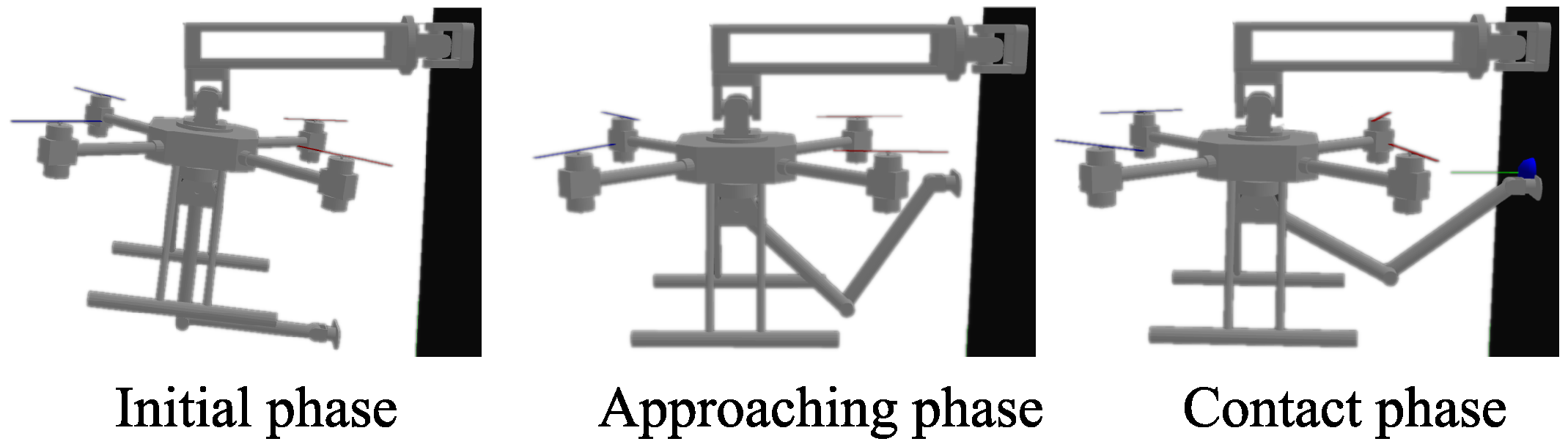
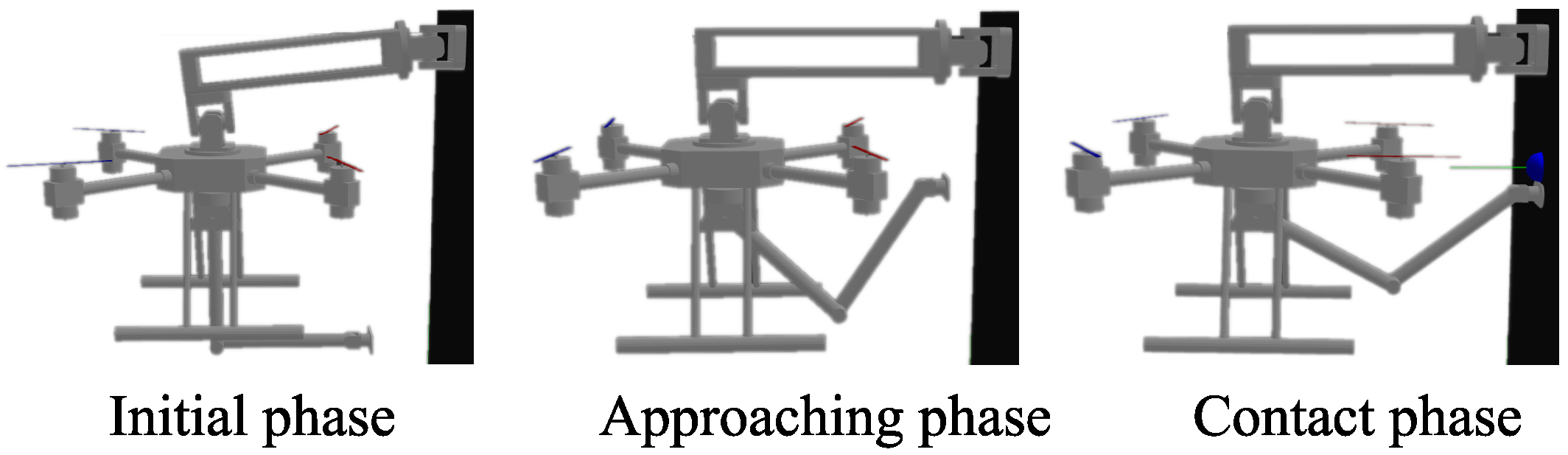
5.1. Physics-Engine-Based Simulation Setup
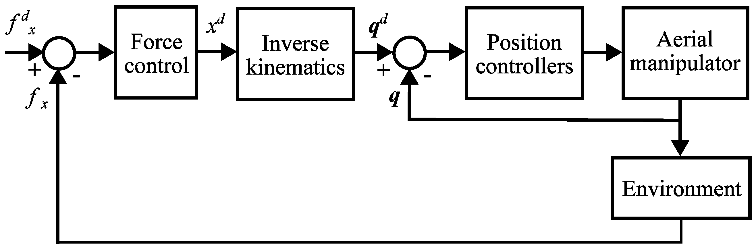
5.2. Position-Based Implicit Force Control
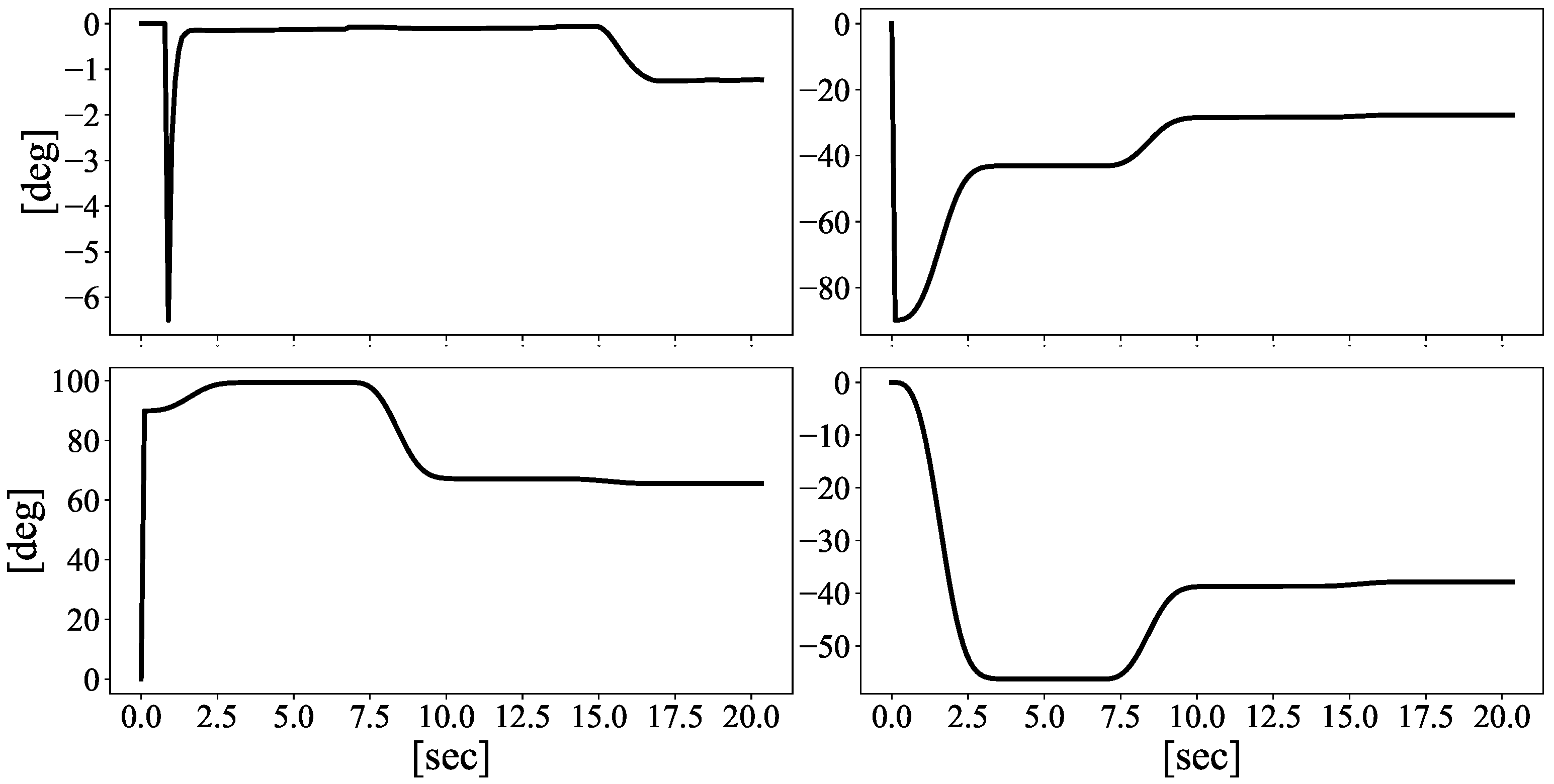
5.3. Horizontal Controlled Force Delivery Results
6. Conclusions
Author Contributions
Funding
Data Availability Statement
Acknowledgments
Conflicts of Interest
References
- Cacace, J.; Orozco-Soto, S.M.; Suarez, A.; Caballero, A.; Orsag, M.; Bogdan, S.; Vasiljevic, G.; Ebeid, E.; Rodriguez, J.A.A.; Ollero, A. Safe Local Aerial Manipulation for the Installation of Devices on Power Lines: AERIAL-CORE First Year Results and Designs. Appl. Sci. 2021, 11, 6220. [Google Scholar] [CrossRef]
- Kessens, C.C.; Horowitz, M.; Liu, C.; Dotterweich, J.; Yim, M.; Edge, H.L. Toward lateral aerial grasping & manipulation using scalable suction. In Proceedings of the 2019 International Conference on Robotics and Automation (ICRA), Montreal, QC, Canada, 20–24 May 2019; pp. 4181–4186. [Google Scholar]
- Ortenzi, V.; Adjigble, M.; Kuo, J.A.; Stolkin, R.; Mistry, M. An experimental study of robot control during environmental contacts based on projected operational space dynamics. In Proceedings of the 2014 IEEE-RAS International Conference on Humanoid Robots, Madrid, Spain, 18–20 November 2014; pp. 407–412. [Google Scholar]
- Umetani, Y.; Yoshida, K. Resolved Motion Rate Control of Space Manipulators with Generalized Jacobian Matrix. Ph.D. Thesis, Tohoku University, Sendai, Japan, 1989. [Google Scholar]
- Ikeda, T.; Ohara, K.; Ichikawa, A.; Ashizawa, S.; Oomichi, T.; Fukuda, T. Aerial manipulator control method based on generalized jacobian. J. Robot. Mechatronics 2021, 33, 231–241. [Google Scholar] [CrossRef]
- Umetani, Y.; Yoshida, K. Continuous path control of space manipulators mounted on OMV. Acta Astronaut. 1987, 15, 981–986. [Google Scholar] [CrossRef]
- Lee, M.Y.; Erdman, A.G.; Gutman, Y. Kinematic/kinetic performance analysis and synthesis measures of multi-DOF mechanisms. Mech. Mach. Theory 1993, 28, 651–670. [Google Scholar] [CrossRef]
- Mermertaş, V. Optimal design of manipulator with four-bar mechanism. Mech. Mach. Theory 2004, 39, 545–554. [Google Scholar] [CrossRef]
- Cinquemani, S.; Giberti, H.; Legnani, G. The generalized jacobian matrix and the manipulators kinetostatic properties. In Proceedings of the ASME 10th Biennial Conference on Engineering Systems Design and Analysis (ESDA), Istanbul, Turkey, 12–14 July 2010; pp. 721–729. [Google Scholar]
- Hu, J.; Wang, T. Minimum base attitude disturbance planning for a space robot during target capture. J. Mech. Robot. 2018, 10, 051002. [Google Scholar] [CrossRef]
- Thomas, J.; Loianno, G.; Daniilidis, K.; Kumar, V. Visual servoing of quadrotors for perching by hanging from cylindrical objects. IEEE Robot. Autom. Lett. 2015, 1, 57–64. [Google Scholar] [CrossRef]
- Ladig, R.; Paul, H.; Miyazaki, R.; Shimonomura, K. Aerial Manipulation Using Multirotor UAV: A Review from the Aspect of Operating Space and Force. J. Robot. Mechatronics 2021, 33, 196–204. [Google Scholar] [CrossRef]
- Zheng, Y.F.; Yin, Q. Coordinating multilimbed robots for generating large cartesian force. IEEE Trans. Syst. Man Cybern. 1990, 20, 849–857. [Google Scholar] [CrossRef]
- Yoshida, H.; Inoue, K.; Arai, T.; Mae, Y. Mobile manipulation of humanoid robots-optimal posture for generating large force based on statics. In Proceedings of the 2002 IEEE International Conference on Robotics and Automation (Cat. No. 02CH37292), Washington, DC, USA, 11–15 May 2002; Volume 3, pp. 2271–2276. [Google Scholar]
- Abi-Farraj, F.; Henze, B.; Ott, C.; Giordano, P.R.; Roa, M.A. Torque-based balancing for a humanoid robot performing high-force interaction tasks. IEEE Robot. Autom. Lett. 2019, 4, 2023–2030. [Google Scholar] [CrossRef]
- Liu, C.; Bera, A.; Tsabedze, T.; Edgar, D.; Yim, M. Spiral zipper manipulator for aerial grasping and manipulation. In Proceedings of the 2019 IEEE/RSJ International Conference on Intelligent Robots and Systems (IROS), Macau, China, 3–8 November 2019; pp. 3179–3184. [Google Scholar]
- Papachristos, C.; Alexis, K.; Tzes, A. Efficient force exertion for aerial robotic manipulation: Exploiting the thrust-vectoring authority of a tri-tiltrotor uav. In Proceedings of the 2014 IEEE international conference on robotics and automation (ICRA), Hong Kong, China, 31 May–7 June 2014; pp. 4500–4505. [Google Scholar]
- Wopereis, H.W.; Hoekstra, J.; Post, T.; Folkertsma, G.A.; Stramigioli, S.; Fumagalli, M. Application of substantial and sustained force to vertical surfaces using a quadrotor. In Proceedings of the 2017 IEEE international conference on robotics and automation (ICRA), Singapore, 29 May–3 June 2017; pp. 2704–2709. [Google Scholar]
- Hamaza, S.; Georgilas, I.; Richardson, T. An adaptive-compliance manipulator for contact-based aerial applications. In Proceedings of the 2018 IEEE/ASME International Conference on Advanced Intelligent Mechatronics (AIM), Auckland, New Zealand, 9–12 July 2018; pp. 730–735. [Google Scholar]
- Orozco-Soto, S.M.; Cuniato, E.; Cacace, J.; Selvaggio, M.; Ruggiero, F.; Lippiello, V.; Siciliano, B. Aerial manipulator interaction with the environment. In Control of Autonomous Aerial Vehicles: Advances in Autopilot Design for Civilian UAVs; Springer: Berlin/Heidelberg, Germany, 2023; pp. 319–347. [Google Scholar]
- Marcellini, S.; D’Angelo, S.; De Crescenzo, A.; Marolla, M.; Lippiello, V.; Siciliano, B. Development of a semi-autonomous framework for NDT inspection with a tilting aerial platform. In International Symposium on Experimental Robotics; Springer: Berlin/Heidelberg, Germany, 2023; pp. 353–363. [Google Scholar]
- Marcellini, S.; Cacace, J.; Lippiello, V. A PX4 Integrated Framework for Modeling and Controlling Multicopters with Til table Rotors. In Proceedings of the 2023 International Conference on Unmanned Aircraft Systems (ICUAS), Warsaw, Poland, 6–9 June 2023; pp. 1089–1096. [Google Scholar]
- Marcellini, S.; Ruggiero, F.; Lippiello, V. Nonlinear Model Predictive Control for Repetitive Area Reconnaissance with a Multirotor Drone. In Proceedings of the 2023 International Conference on Unmanned Aircraft Systems (ICUAS), Warsaw, Poland, 6–9 June 2023; pp. 515–522. [Google Scholar]
- Ullah, H.; D’Angelo, S.; Ruggiero, F.; Lippiello, V.; Orozco Soto, S.M. Horizontal Sustained Force Delivery with an Aerial Manipulator using Hybrid Force/Position Control. In Proceedings of the 25th IEEE International Carpathian Control Conference (ICCC), Krynica Zdrój, Poland, 22–24 May 2024; pp. 1–5. [Google Scholar]
- Tsukagoshi, H.; Watanabe, M.; Hamada, T.; Ashlih, D.; Iizuka, R. Aerial manipulator with perching and door-opening capability. In Proceedings of the 2015 IEEE International Conference on Robotics and Automation (ICRA), Seattle, WA, USA, 26–30 May 2015; pp. 4663–4668. [Google Scholar]
- Estrada, M.A.; Mintchev, S.; Christensen, D.L.; Cutkosky, M.R.; Floreano, D. Forceful manipulation with micro air vehicles. Sci. Robot. 2018, 3, eaau6903. [Google Scholar] [CrossRef] [PubMed]
- Boudreau, R.; Nokleby, S.; Gallant, M. Wrench capabilities of a kinematically redundant planar parallel manipulator. Robotica 2021, 39, 1601–1616. [Google Scholar] [CrossRef]
- Chiacchio, P.; Bouffard-Vercelli, Y.; Pierrot, F. Evaluation of force capabilities for redundant manipulators. In Proceedings of the IEEE International Conference on Robotics and Automation, Minneapolis, MN, USA, 22–28 April 1996; Volume 4, pp. 3520–3525. [Google Scholar]
- Yoshikawa, T. Manipulability of robotic mechanisms. Int. J. Robot. Res. 1985, 4, 3–9. [Google Scholar] [CrossRef]
- Yoshida, K.; Umetani, Y. Control of space manipulators with generalized Jacobian matrix. In Space Robotics: Dynamics and Control; Springer: Berlin/Heidelberg, Germany, 1993; pp. 165–204. [Google Scholar]
- Siciliano, B.; Khatib, O.; Kröger, T. Springer Handbook of Robotics; Springer: Berlin/Heidelberg, Germany, 2008; Volume 200. [Google Scholar]
- Spong, M.W.; Hutchinson, S.; Vidyasagar, M. Robot Modeling and Control; John Wiley & Sons: Hoboken, NJ, USA, 2020. [Google Scholar]
- Orozco Soto, S.M.; Ruggiero, F.; Lippiello, V. Globally attractive hyperbolic control for the robust flight of an actively tilting quadrotor. Drones 2022, 6, 373. [Google Scholar] [CrossRef]
- Polverini, M.P.; Formentin, S.; Merzagora, L.; Rocco, P. Mixed data-driven and model-based robot implicit force control: A hierarchical approach. IEEE Trans. Control Syst. Technol. 2019, 28, 1258–1271. [Google Scholar] [CrossRef]


 Rigid environment.
  Force ellipsoid axes.
  Manipulator links.
  UAV.
Rigid environment. Force ellipsoid axes. Manipulator links. UAV.
UAV.
Rigid environment. Force ellipsoid axes. Manipulator links. UAV. Rigid environment. Force ellipsoid axes. Manipulator links. UAV.
Rigid environment. Force ellipsoid axes. Manipulator links. UAV.
Rigid environment. Force ellipsoid axes. Manipulator links. UAV.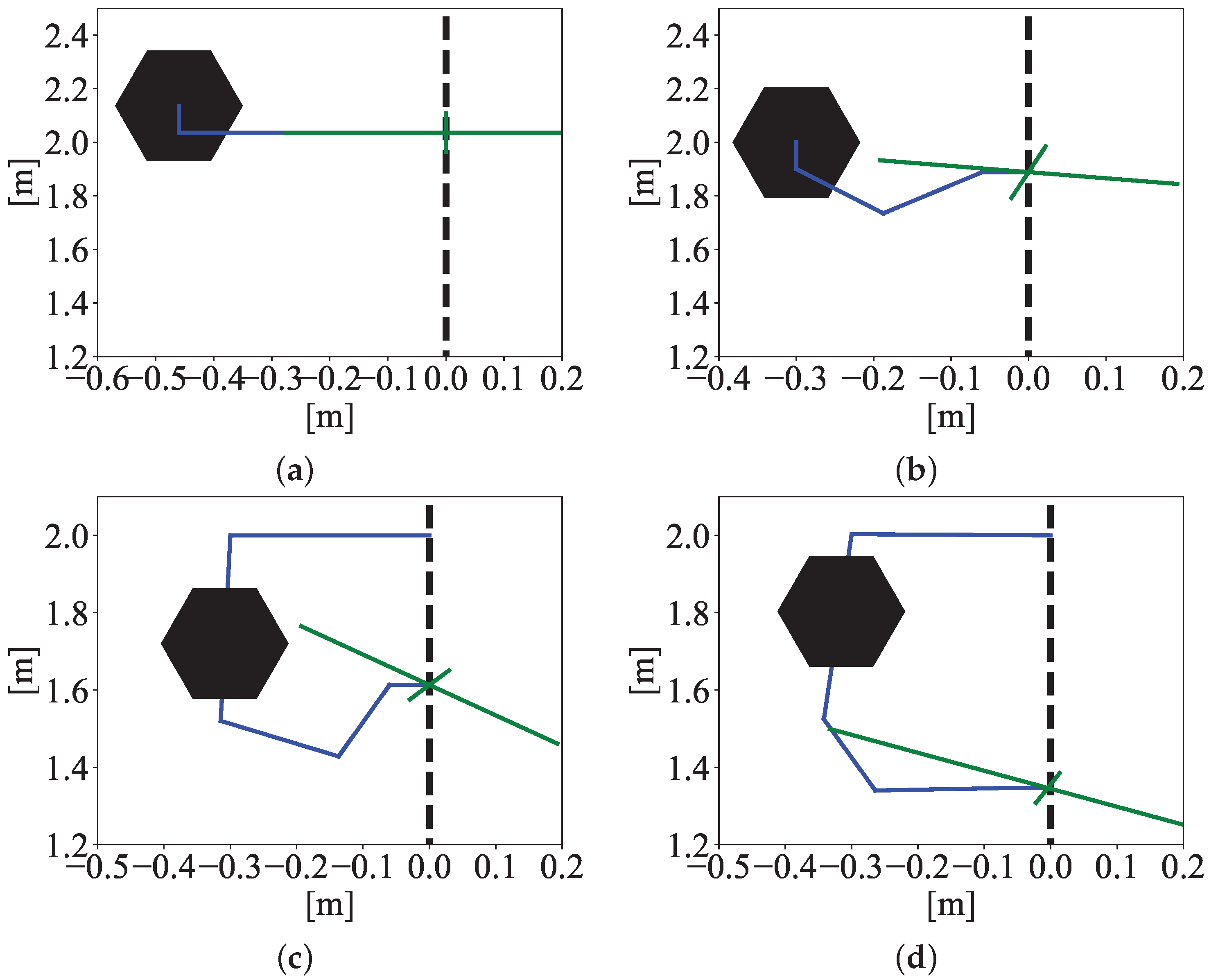 Normal-Jacobian-based force ellipsoid.
  Generalized-Jacobian-based force ellipsoid. Manipulator links. UAV.
Normal-Jacobian-based force ellipsoid. Generalized-Jacobian-based force ellipsoid. Manipulator links. UAV.
Generalized-Jacobian-based force ellipsoid. Manipulator links. UAV.
Normal-Jacobian-based force ellipsoid. Generalized-Jacobian-based force ellipsoid. Manipulator links. UAV.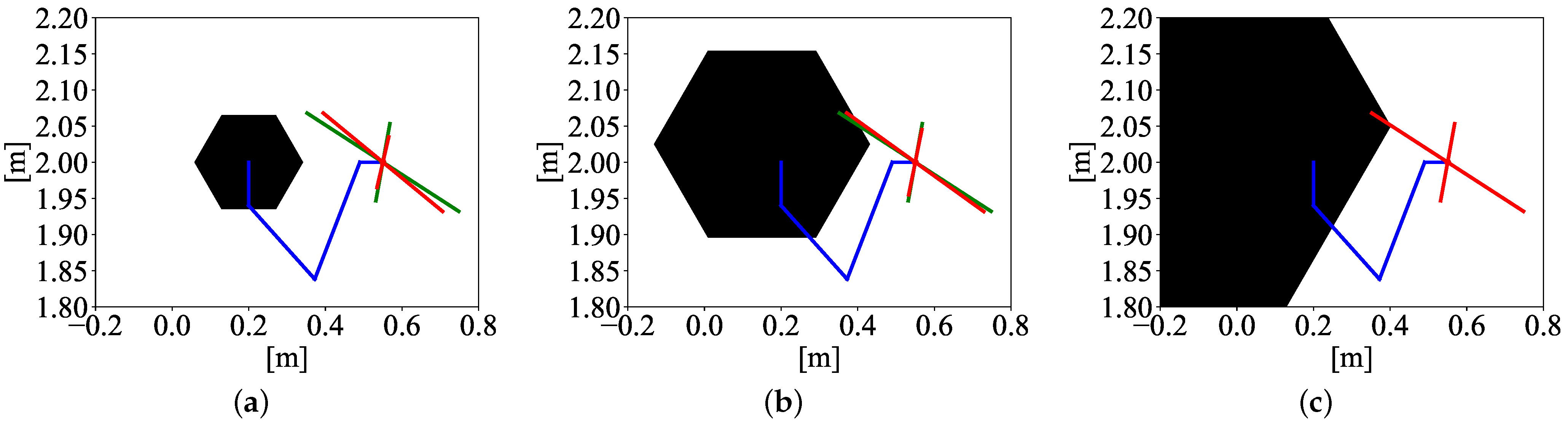


 Desired force.
  Measured force.
Desired force. Measured force.
Measured force.
Desired force. Measured force.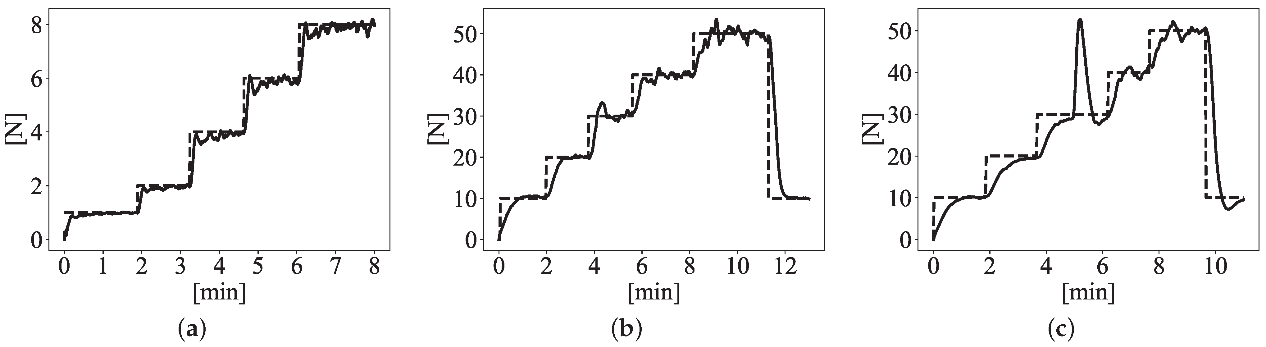

| Work | Robot Features | Achieved Force | Time Sustained |
|---|---|---|---|
| Free-flying aerial manipulators | |||
| Papachristos et al. (2014) [17] | 2.254 [kg] UAV with 1-DOF end-effector | Estimated 18 [N] | 30 [s] |
| Wopereis et al. (2017) [18] | 1.5 [kg] UAV with rod end-effector | Estimated 14 [N] | 240 [s] |
| Hamaza et al. (2018) [19] | 2 [kg] UAV rod 2-DOF end-effector | Measured 60 [N] | 1.5 [s] |
| Orozco et al. (2023) [20] | 5 [kg] UAV with 3-DOF manipulator | Measured 2.2 [N] | 80 [s] |
| Ullah et al. (2024) [24] | 5 [kg] UAV with 3-DOF manipulator | Measured 8 [N] | 120 [s] |
| Perched aerial manipulators | |||
| Tsukagoshi (2015) [25] | Experimental results with 1.7 [kg] UAV with soft-bag actuated end-effector | Estimated 4 [Nm] torque | n/a |
| Estrada (2018) [26] | Experimental results with 200 [g] UAV and winch | Lifted 40 [N] | n/a |
| Parameter | Free-Flying | Attached with One | Attached with Two |
|---|---|---|---|
| Passive Joint | Passive Joints | ||
| – | 0.38 | 0.45 | |
| 0.2 | 0.2 | 0.38 | |
| 0.2 | 0.2 | 0.2 | |
| 0.06 | 0.06 | 0.2 | |
| – | – | 0.06 |
| Data | Free-Flying with | Free-Flying with | Attached with One | Attached with Two |
|---|---|---|---|---|
| Stick | Moving Arm | Passive Joint | Passive Joints | |
| Average | 0.5156 | 0.3756 | 0.6453 | 0.6140 |
| Variance | 0.0 | 0.0003 | 0.0099 | 0.0055 |
| Std. deviation | 0.0 | 0.0175 | 0.0999 | 0.0744 |
| Data | Attached with One | Attached with Two |
|---|---|---|
| Passive Joint | Passive Joints | |
| RMSE | 3.84 | 7.49 |
| AVG Convergence time | 22.5 s | 49.2 s |
Disclaimer/Publisher’s Note: The statements, opinions and data contained in all publications are solely those of the individual author(s) and contributor(s) and not of MDPI and/or the editor(s). MDPI and/or the editor(s) disclaim responsibility for any injury to people or property resulting from any ideas, methods, instructions or products referred to in the content. |
© 2024 by the authors. Licensee MDPI, Basel, Switzerland. This article is an open access article distributed under the terms and conditions of the Creative Commons Attribution (CC BY) license (https://creativecommons.org/licenses/by/4.0/).
Share and Cite
Orozco Soto, S.M.; Lippiello, V. Increasing Horizontal Controlled Force Delivery Capabilities of Aerial Manipulators by Leveraging the Environment. Robotics 2024, 13, 147. https://doi.org/10.3390/robotics13100147
Orozco Soto SM, Lippiello V. Increasing Horizontal Controlled Force Delivery Capabilities of Aerial Manipulators by Leveraging the Environment. Robotics. 2024; 13(10):147. https://doi.org/10.3390/robotics13100147
Chicago/Turabian StyleOrozco Soto, Santos Miguel, and Vincenzo Lippiello. 2024. "Increasing Horizontal Controlled Force Delivery Capabilities of Aerial Manipulators by Leveraging the Environment" Robotics 13, no. 10: 147. https://doi.org/10.3390/robotics13100147