Review

A Review of Mechanical Design Approaches for Balanced Robotic Manipulation

1
Department of Industrial Engineering, University of Padova, Via Venezia 1, 35131 Padova, PD, Italy
2
Faculty of Mechanical Engineering, TU Delft, 2628 CD Delft, The Netherlands
*
Authors to whom correspondence should be addressed.
Robotics 2025, 14(11), 151; https://doi.org/10.3390/robotics14110151
Submission received: 28 August 2025 / Revised: 16 October 2025 / Accepted: 24 October 2025 / Published: 26 October 2025
(This article belongs to the Section Industrial Robots and Automation)

Abstract

Robot manipulators are suitable for many industrial tasks, such as assembly and pick-and-place operations. However, high-acceleration motions result in shaking forces and moments to the base, which can cause vibration of the manipulator and instability in the case of a mobile base. Furthermore, gravity compensation of the manipulator links requires additional motor torque, which can increase energy consumption. Balanced manipulators address these problems by employing a mechanical design that results in the balancing of gravity and other static forces, or the removal of shaking forces and/or moments. This review paper provides an overview of mechanical design approaches for balanced robotic manipulation, with an emphasis on experimentally prototyped designs. We first define the types of balancing according to the literature. We then provide an overview of different approaches to the mechanical design of balanced manipulators, along with simple examples of their implementation. Experimental prototypes in this field are then comprehensively presented and summarized to allow readers to compare their development maturity. At the end of the paper, we outline challenges and future directions of research.

1. Introduction

Robotic manipulation has been an active field of research for many decades. These manipulators are used in a variety of industrial tasks, such as inspection, assembly, pick and place, etc. They are attached to rigid bases mounted on the ground or to mobile robots [1]. Ground-fixed manipulators are common in industrial automation applications such as manufacturing and warehousing [2]. Mobile manipulators, consisting of a moving base and a manipulator, operate in a variety of environments [3], such as ground terrain (wheeled robots), underwater (autonomous underwater vehicles) [4], air (unmanned aerial vehicles) [5,6,7], or space (satellites) [8]. The manipulator provides the robot with the ability to interact with the environment through a sensor or actuator, called a payload, mounted at the end of the manipulator’s kinematic chain, called the end-effector. Examples of payloads include a camera for inspection or a gripper for pick and place and assembly tasks.
In gravitational environments, the manipulator exerts static forces and moments on the base due to the gravitational force acting on its links [9]. Furthermore, during motion, the manipulator exerts additional inertial forces and moments on the base, termed shaking forces and shaking moments [10]. For fast accelerations on a ground-fixed base, these can induce vibrations [11]. For mobile manipulators, the base undergoes unwanted disturbances that move the base and have to be compensated for through control of the base while executing the manipulation task. These result in a lack of precision, low dexterity, or even instability of the base.
A solution to this problem is to design balanced robotic manipulators for which the static forces and moments and/or shaking forces and moments are mitigated or negligible. The mechanical design of these manipulators facilitates different levels of balancing behaviors, from compensating the gravity force to being fully reactionless for any motion. By reducing the shaking forces and moments, we reduce the disturbances and vibrations on the base, thereby increasing precision and reducing fatigue.
A related problem is to design statically balanced manipulators, where the static forces, particularly gravity, are balanced through mechanical design. A statically balanced robot manipulator has lower gravity compensation torques, which increases the maximum allowable payload at the end-effector under static conditions [12]. Approaches that address shaking force and shaking moment balancing often result in static balance as well.
In the 19th century, Otto Fischer studied the shaking force balancing of Crank-Slider mechanisms and developed the method of principal vectors for calculating the inverse dynamics of a human in motion, which was also relevant for balancing [13]. The method was mentioned by Berkhof and Lowen in 1968 [14], who then began a detailed study on various approaches for static and shaking force/moment balancing [15,16].
In the period from 1970 to now, research on balanced mechanisms has been further developed by Agrawal [17,18], Arakelian [19], Gosselin [9], Kochev [20], van der Wijk [21], and others. The focus during this period has been on developing theoretical tools to derive the mathematical relationships that result in balance, which are known as the balance conditions. These tools were then employed to analyze novel balanced mechanism design approaches. In the past decade, some of these concepts have also been validated through experimental prototypes applied in real-world scenarios.
Whereas the theoretical developments in balanced mechanisms began in the 19th century, the practical applications in robot manipulation have only seen adoption in the last three decades after the advent of industrial robotics, with a notable uptake in the last 15 years. Previous review papers provide a high-level overview [22], an in-depth examination [10,19,20], or a comprehensive analysis [23] of theoretical approaches with numerical examples. However, a review of practical prototypes built and tested experimentally in this field, along with the developments since the last review by Wei and Zhang in 2020 [22], is missing. The goal of this review paper is to provide an overview of gravity, static, shaking-force, and shaking-moment balancing approaches relevant to robotic manipulation, and provide a concise yet comprehensive review of real-world prototypes and their experimental results.
In addition to extensive theoretical and experimental work on creating balanced rigid body manipulators, some preliminary research has also been conducted on the balance of flexible bodies [24,25,26,27]. In particular, the reduction in vibration modes through balancing holds many advantages for high payload-to-weight ratio tasks.
Force and moment balancing for robot manipulation can also be achieved using control and motion planning-based approaches, applied in space manipulation applications [28,29] and legged robot locomotion [30]. A hybrid approach applying control-based balancing for soft robotics links for legged robotic links was also investigated [31,32], which is outside the scope of robot manipulation. These approaches constitute a separate field of research employing fundamentally different mathematical tools and optimization goals than those used in mechanical design. For that reason, we will exclude control-based approaches from this review.
The structure of the paper is as follows: Section 2 outlines the types of balancing with their definitions. The approaches used to achieve various balancing types are summarized with relevant literature in Section 3. Experimental prototypes are categorized and elaborated in detail in Section 4. Based on our analysis of the development of the field so far, we provide an assessment of challenges and future directions for this field in Section “Challenges and Future Work”. The conclusion (Section 5) summarizes our review findings.

2. Types of Balancing

We define a robot manipulator as a mechanism consisting of rigid links connected by joints that allow motion, attached to a ground-fixed or mobile base with one or more fixed joints for attachment. The combination of spatial geometry and joint type determines the degrees of freedom (DOF) of their motion. The most common joints are revolute (1-DOF rotational motion) and prismatic (1-DOF translational). To facilitate spatial (3D) motion, spherical and universal passive joints that allow motion with multiple DOF are also used. The manipulator carries out the intended task by moving the payload at the end-effector (a sensor or actuated mechanism such as a gripper) attached at the end of a kinematic chain. The manipulator can be serial, consisting of a single open-chain of links, or parallel, consisting of one or more closed chains. Simple 2D examples of both types of robotic manipulator platforms are shown in Figure 1.
As a manipulator moves, it exerts forces and moments on the base. These originate from (1) gravity, (2) motion of the links (acceleration, centrifugal, and Coriolis components), and (3) external forces/moments, such as actuators, contact forces/moments, loads, and support constraint forces.
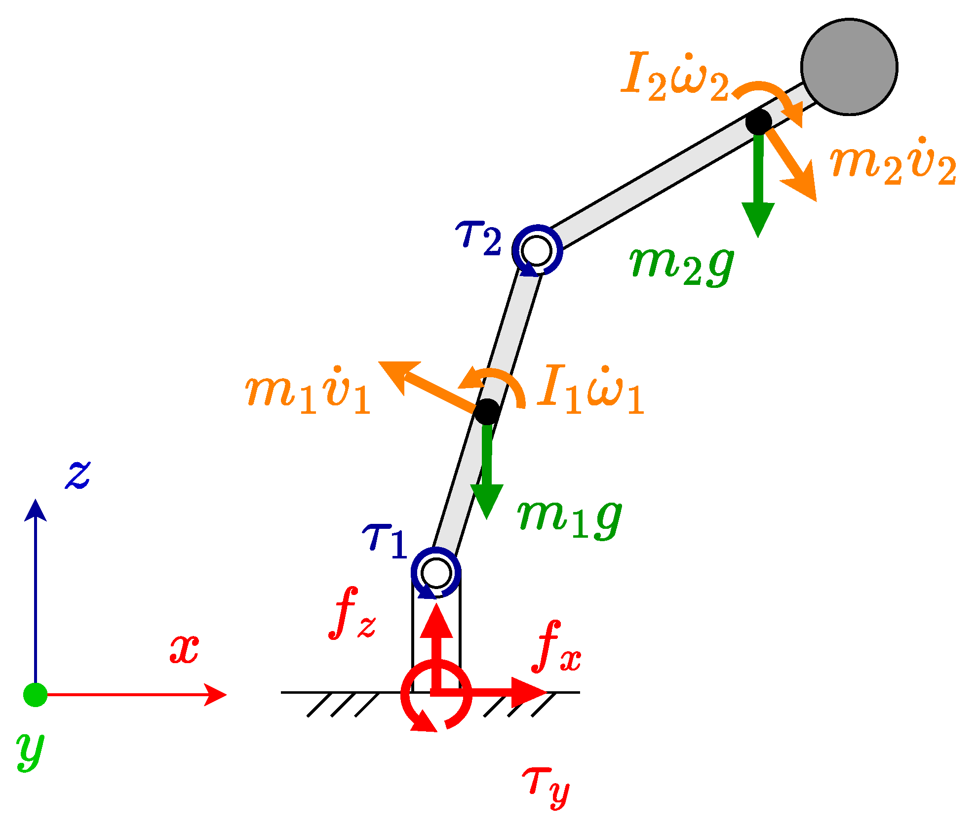
As an example, these are illustrated for a serial planar manipulator in Figure 2. There are two reaction forces and one reaction moment for two DOF motion, which counteract the forces and moments generated by the manipulator. For a spatial manipulator, there are three reaction forces and three reaction moments, corresponding to six DOF motion.
We first define the kinematics of the robotic manipulator using the Denavit–Hartenberg convention. It consists of n moving bodies (links) attached to joints, both indexed as i. Frame O B is the base-fixed reference frame of the manipulator, and each frame O i is fixed to link i with its origin at the parent joint. Each body has mass m i R , inertia I i R 3 × 3 , and center of mass at r i R 3 with respect to O B . The system is described in terms of generalized coordinates θ = θ 1 θ 2 θ n , which are determined by the joint DOF. We also denote as r C R 3 the position of the center of mass of the system. A simple illustrative example of a 2-DOF open-chain planar robotic manipulator composed of revolute joints is shown in Figure 3.
For a closed-chain manipulator, the motion of its links is constrained, and additional closed-loop kinematic equations are needed to fully define the end-effector motion. Using this approach can often remove redundant generalized coordinates.
According to [9], we identify the following types of balancing: (1) gravity, (2) static, (3) shaking force (or force), (4) shaking moment (or moment), and (5) dynamic (both shaking force and shaking moment). A moment-balanced mechanism also has force balance properties, as shown in Section 2.3. We provide mathematical definitions from the literature for these types of balancing in the following sections.

2.1. Static and Gravity Balancing

A mechanism is defined as statically balanced if the static forces (e.g., the gravity force from the weight of the links and forces exerted by energy-conserving components) are balanced so that the actuators do not need to apply torque to maintain the manipulator in its equilibrium configuration [9,33]. The utility of such balancing can be observed in Figure 2, where an unbalanced manipulator requires actuation torques to maintain the manipulator in this configuration.
A definition is provided from [17] in terms of the potential energy of the system, which remains constant T ¯ for all possible configurations θ , where T g ( θ ) is the total gravitational potential energy and T p ( θ ) is the potential energy stored by other mechanical elements (e.g., springs):
T ¯ = T p ( θ ) + T g ( θ )
Static balancing purely for the gravity force is called gravity balancing or gravity compensation. In (2), where f g is the total gravity force acting on all the system bodies, f p is the total gravity-aligned (z-axis) force from potential conserving mechanical elements (e.g., springs or coupled counter masses), and f z is the reaction force applied by the base:
f z + f g + f p = 0 .

2.2. Force Balancing

A mechanism is defined as shaking-force balanced if the net reaction force exerted on the base is constant for any motion of the links [9], which occurs when the net forces about the center of mass of the manipulator are zero.
The linear momentum L R 3 of the system is the summation of linear momenta of n bodies with index i, each with mass m i and velocity vector v i = r i ˙ , with respect to the balance position (manipulator center of mass). In a balanced mechanism, it remains constant for any velocity within the range of admissible motions of the manipulator:
L = i = 1 n m i v i = L ¯ .
The force balance condition (3) can be interpreted in two other ways:
  • As the change in linear momentum is caused by a net force on the manipulator f R 3 , these are zero about the center of mass for any configuration:
    d d t L = f = 0 .
  • The linear momentum of the system can also be expressed in terms of the velocity of the manipulator center of mass, where m t is the total mass:
    L = i = 1 n m i v i = m t r ˙ C
    As m t is constant, this means that in a force-balanced system r ˙ C = 0 , hence the center of mass r C remains static at fixed position r ¯ C :
    r = 1 M i = 1 n m i r i = r ¯ C .
Note that for solving the force balance conditions, it is more useful to express r i and r C as functions of the generalized coordinates θ .

2.3. Moment Balancing

For a system to be shaking moment balanced, the angular momentum K R 3 of the manipulator about the balance point (the center of mass) must remain constant for the range of admissible motions:
K = i = 1 n I i ω i = K ¯ ,
where I i R 3 × 3 and ω i R 3 are the inertia and angular velocity of body i with respect to the center of mass.
This also implies that the change in angular momentum, which is caused by net moments on the manipulator τ R 3 , with respect to the balance point, is zero:
d d t K = τ = 0
A body experiencing linear motion perpendicular to a rotational axis also has angular momentum with respect to that axis. The relationship between the linear momentum of a body L i and its corresponding angular momentum component K i is expressed as the following, where r i is the position vector in the fixed-frame coordinates:
K i = r i × L i = m i ( r i × v i )
Furthermore, moments are also caused by static forces acting perpendicular to the rotational axis, which contribute to the reaction moments. Therefore, a moment-balanced system is also force-balanced, as zero net force about the center of mass is a necessary condition for zero net moments.

3. Approaches to Design Balanced Manipulators

Different types of balancing can be achieved by modifying the design of a manipulator by adding components that introduce balancing in the system’s dynamic behavior. These components are added at selected places in the manipulator in order to balance the system. The required parameters of these components are determined through resolving the balance conditions of the dynamic equations with the added components. In choosing the type and position of these components, there is often a tradeoff between mass/inertial addition and space.
We categorize approaches to designing balanced manipulators into three broad categories: Passive Component Addition, Active Component Addition, and Inherently Balanced Design. In addition to this, the Synthesis approach combines the aforementioned and/or control-based approaches. The definition of each approach and the sub-approaches within these categories are explained in the following subsections, accompanied by simple illustrative examples.

3.1. Passive Component Addition

In passive component addition, non-actuated elements are added to the mechanism, resulting in static, force, or moment balancing. These elements do not require any input forces or torques, and their motions are coupled with the kinematics of the original unbalanced mechanism. Therefore, the total energy and momentum of the system remain constant, depending on the type of balance desired. Several types of balancing components are used to achieve different types of balance, which are summarized below.

3.1.1. Springs

Springs can be used to achieve gravity and static balancing, as they store potential energy to keep the mechanism in an equilibrium configuration [33]. The total potential energy in the system remains constant; however, the springs only balance the static forces, such as gravity and other springs. Joint torques, as well as the dynamic forces and moments from linear and rotational acceleration, still result in shaking forces and moments; thus, a spring-balanced manipulator cannot be force- or moment-balanced.
Balancing the gravity force with springs also reduces the joint torques through gravity compensation at the equilibrium position, which increases the maximum allowable payload and reduces energy consumption. For this reason, springs have been extensively demonstrated to be an effective balancing method for manipulators, particularly where the goal is to minimize energy consumption with minimal mass additions.
A simple example of a 1-DOF manipulator consisting of a link balanced by a single linear spring is shown in Figure 4. We assume that deflections in the x-axis are negligible, such that the spring force only acts in the z-axis, in order to simplify the balance equations.
If we look at the moment balance about the joint origin, we can see that there is an equilibrium for which τ 1 = 0 and θ 1 0 , which is the first equation for static balance, where f g is the gravity force and f s is the spring force:
f s l s f g l g = 0 .
The static balance equation in the gravity axis for the example shown is:
f z + f s f g = f z k d f g = 0 ,
where we expand the spring force f s = k d according to the relationship between the spring stiffness k and the spring extension or compression along the positive z-axis d.
At equilibrium, the spring is compressed ( d < 0 ); hence k d > 0 , and the gravity force is balanced by both the spring and reaction forces. A torque τ 1 is required to rotate the link by providing rotational acceleration as well as counteracting the spring or gravity force away from the equilibrium configuration, which is why the spring-balanced system only results in static, and not force or moment balance.
Spring additions for static and gravity balancing of manipulators can reach significant levels of complexity. Static balancing using springs has been investigated for multiple DOF serial [34], parallel planar [35], and spatial mechanisms [36,37]. A zero free length spring can also be created through a cable and pulley arrangement, and is often used for static balancing [38,39].
A variety of configurations—such as spring-linkage combinations, as well as pulley, cross-mechanism, and hydro-pneumatic springs for torque compensation—were investigated for the static balancing of articulated robots in [40]. Torsional springs are also an effective and space-efficient method of balancing serial manipulators [41,42]. Gear-spring modules were designed in [43] for static balancing of a Delta-robot, where the theoretical peak torques are reduced between 38.4 and 55.4% within 86% of the original kinematic workspace. A patent [44] also describes an internal spring-based weight-balancing device for a robotic arm link.
Methods for calculating optimal spring configurations have also been widely investigated, for example, by analyzing the stiffness matrix [45,46], genetic optimization [34], and eigenvalue analysis of the joint-space potential energy function [47]. Several experimental prototypes employing springs for gravity and static balancing are summarized in Section 4.

3.1.2. Counter Mass (CM)/Counter Inertia (CI)

Masses can be added to modify the center of mass motion. By balancing individual or groups of links with counter masses, the center of mass of the mechanism can be fixed to a static position or constrained to motion along an axis; for example, along the gravity axis in the case of gravity balancing, or fixed at a point for all motions, thereby achieving force balance.
Whereas balancing links with revolute joints using counter masses is simple due to the coupled motion of the link and counter mass (CM) [19], more complex solutions, such as a negatively geared rack and pinion or Scott–Russell mechanisms, are required for the passive balancing of prismatic joints [48].
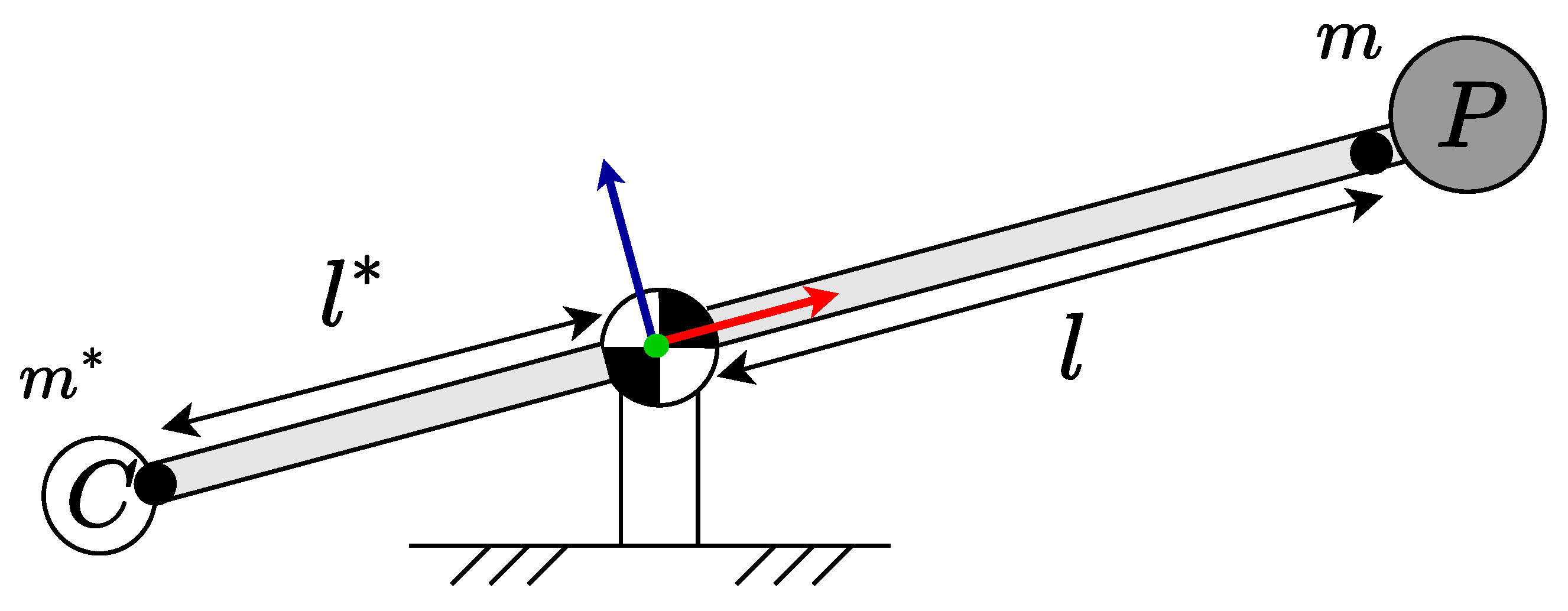
A simple 1-DOF manipulator consisting of a revolute joint, force-balanced with a single CM, is illustrated in Figure 5. The original link has mass m, and its center of mass is at length l along the joint-frame x axis (shown by the red arrow). A CM is positioned opposite, with the link extended in the opposite direction (counter-link). The mass of the counter link extension with counter mass is m * , and its center of mass is at l * . For the mechanism to force balance about the joint origin, the relationship between the link and counter-link kinematic parameters is [49]:
m * l * = m l .
There is a linear tradeoff between the proportions of m * : m and l * : l , i.e., to achieve minimal mass increase, the length of the counter mass must be increased. For example, in (12), we can select m * = m / 2 and l * = 2 l , which achieves force balance with a 50% increase in total mass.
The most common application of CM is to force balance low DOF serial [50] or parallel mechanisms [35]. CMs can also be applied to spatial parallel manipulators to achieve force balancing, with effective exploitation of symmetries [51]. In [52,53], counter masses are added to force balance the arms of a spatial three DOF robot manipulator (see Section 4.3 for more details).

3.1.3. Counter Rotating Inertia (CR)/Counter Rotating Counter Mass (CRCM)

Counter Rotating Inertias or simple Counter Rotations (CR) add moments to the system in order to counteract the rotational imbalance [54]. They are compact; however, they can also result in significant mass addition. An additional inertial element is negatively geared to the manipulator joint and cancels the moments caused by the rotational motion of the links [55]. For serial and many types of closed-chain manipulators, moment balancing cannot be achieved through CM/CI alone, and CR is required [19,56,57]. However, the implementation of CR can be complex in practice, as mechanical transmissions, such as gear trains, are required to couple their motion to the manipulator.
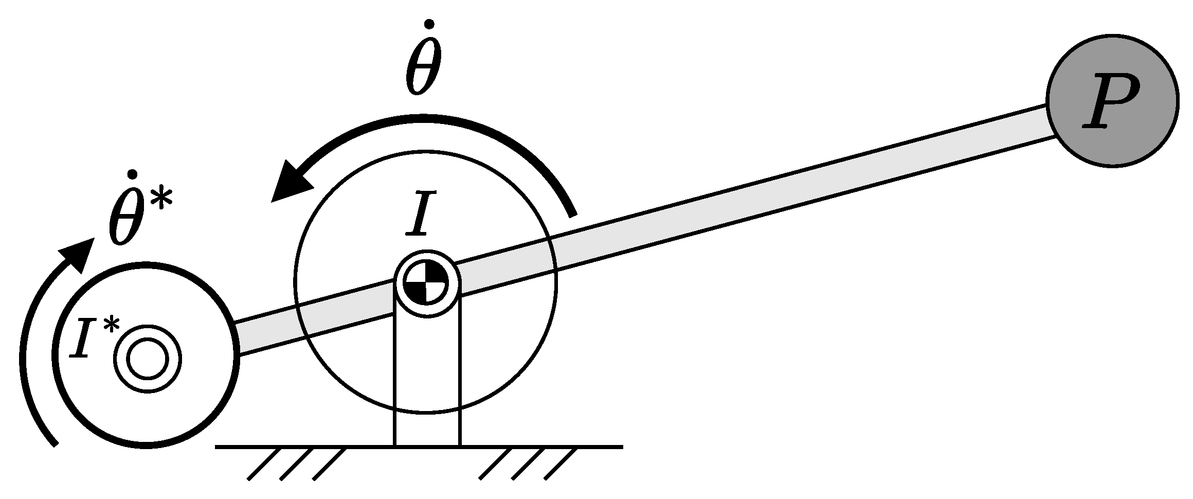
An extension to the earlier 1-DOF planar CM example (Figure 5) is shown in Figure 6, where an additional CR is added to moment balance the manipulator. The link with the counter mass has combined planar inertia I R about the center of mass (also the joint origin). A CR, geared to the revolute joint with a constant transmission ratio k, rotates in the opposite direction with angular velocity θ ˙ * = k θ ˙ and has planar inertia I * R about its centroid. Using the conservation of angular momentum, the relationship between the CR and link motions for the balanced manipulator is as follows [55]:
I θ ˙ I * k θ ˙ = ( I k I * ) θ ˙ = 0 .
Counter rotations can also be integrated with counter masses to form a single unit called a Counter Rotating Counter Mass (CRCM), which is more compact, requires a lower mass/inertia addition, and can achieve both force and moment balance together [58]. A simple 1-DOF manipulator balanced with a CRCM is illustrated in Figure 7. The planar inertia of the CRCM I * R (measured about the axis of the joint connecting the CRCM to the main link) includes both a mass component, which assists in the force balance of the link, as well as its own inertial contribution from the material that is considered in the moment balance Equation (13).

3.1.4. Additional Linkage Mechanism (ALM)

Mechanisms consisting of links and moving masses are added to keep the center of mass of the system at a fixed point during motion. Examples include pantographs [35], idler loops, duplicate mechanisms [55], or counter mechanisms consisting of linkages and CR elements [59].
An example of a duplicate mechanism for the dynamic balancing of a 1-DOF manipulator is shown in Figure 8. The mechanism is mirrored both vertically and horizontally. The center of mass is in the center of the manipulator, and I is the inertia of each component about it. The total mass and inertia of the system are increased to four times the original.
Van der Wijk et al. compare the various configurations of CR, CRCM, and ALMs in terms of the tradeoff between mass and space addition to achieve dynamically balance for 1 and [54] 2 DOF [55] planar serial manipulators. Theoretical derivations and simulated results show that ALM-based approaches result in the lowest mass addition; however, this comes with a quadrupling of the space required. CRCM achieves dynamic balance for a larger mass addition, but without a significant increase in space. With optimized transmission and inertial shape, ALM can be matched or improved.
Laliberte and Gosselin [59] built and tested prototypes of several ALM arrangements for a 2-DOF manipulator and demonstrated the reduction in reaction moments compared to their unbalanced equivalents (see Section 4.4).

3.2. Active Component Addition

This approach for balancing requires adding an actuated element to the manipulator that actively generates forces and/or torques to cancel out the inertial forces and moments generated by the mechanism during motion.

3.2.1. Active CM/CR/CRCM

This is similar to a passive CM or CRCM, but driven by an actuation force and/or torque. They allow for the decoupling of joint and CM/CR motions, which facilitates more compact sizing and convenient positioning. Active CM has been proposed for both static and force balancing [60], depending on the control method and maximum extension of the component. Active CRCM can be used to consolidate multiple Counter Rotations into one, in order to balance an entire mechanism without requiring complex gear mechanisms [61].
In most designs, a moving mass is actuated with an actuated prismatic joint (motor and slider) to keep the center of mass offset to a minimum along a single axis, which is a form of gravity or static balancing. A patent was filed in [62] describing an intelligent adaptive active balancing CM for gravity balancing. The authors of [6,63] use the drone battery as an actively controlled CM for statically balancing an aerial manipulator. Other experimental prototypes that move the battery or other counter masses for the force balance of serial manipulators are presented in [64,65,66]. These are described in more detail in Section 4.3.
A bio-inspired tail design that uses aerodynamic drag to balance a robot mechanism was developed in [67], and was shown to be more effective than reaction wheels (a form of Active CR) in balancing a robotic mechanism.

3.2.2. Active Dynamic Balancing Unit (ADBU)

These integrate Active CM and CR in all axes to provide full six-DOF balancing in the form of a single actively driven unit. They are highly compact and particularly effective in multiple DOF parallel or kinematically redundant spatial manipulators, where it is infeasible to achieve complete moment balance through the addition of passive elements alone. In [68], a mechatronic design of an ADBU is presented, which was proposed earlier in [69] as a method to dynamic balance a Delta robot that is already statically balanced with counter masses.
Active balancing in the form of a redundant drive was developed and experimented with as a method of improving the dynamic balance of a flexible four-bar linkage [27].

3.3. Inherent Balancing

For many types of manipulator linkage arrangements, the whole manipulator can be dynamically balanced in the design stages through the derivation of the balancing conditions. These are the required relationships between link geometries, mass, and inertia that result in the desired type of balance. The required mass and inertial parameters of each link in the balanced manipulator are achieved through modifying the link shape [70,71] or mass/inertial additions.
Typically, the balance conditions are found through momentum balance equations. We can express (3) as a function of the Mass Matrix M ( θ ) and generalized joint velocities θ ˙ :
L = M ( θ ) θ ˙ .
From (3), we can see that L = 0 when M ( θ ) = 0 for all admissible θ ˙ . This is typically done by setting all the coefficients of θ variables in M ( θ ) to 0. The derived equations are known as the force balance conditions. Alternative methods of finding force balance conditions are to solve for the center of mass motion (6) or zero net force (4).
Similarly, we can express the angular momentum (7) as a function of θ ˙ and mass-inertial matrix I ( θ ) :
K = I ( θ ) θ ˙ .
From (7), we can see that setting I ( θ ) = 0 for all admissible θ ˙ results in K = 0 . The common approach is the same as for the force balance conditions, which is to set all the coefficients of θ in I ( θ ) to 0 [15].
Note that for inherently balanced designs, the moment balance conditions also fulfill the force balance conditions, as explained in Section 2.3. Hence, these are typically force or dynamically balanced.
Typically, (14) and (15) are formulated through the calculation of open chains for all the linkages, followed by the substitution of closed-loop constraint equations to remove redundant joint coordinates [21]. Alternative methods to using momentum equations include algebraic formulations based on complex numbers [72] or screw theory [73].
Some approaches based on balancing established kinematic designs are summarized in the following sub-sections.

3.3.1. Parallel Mechanisms

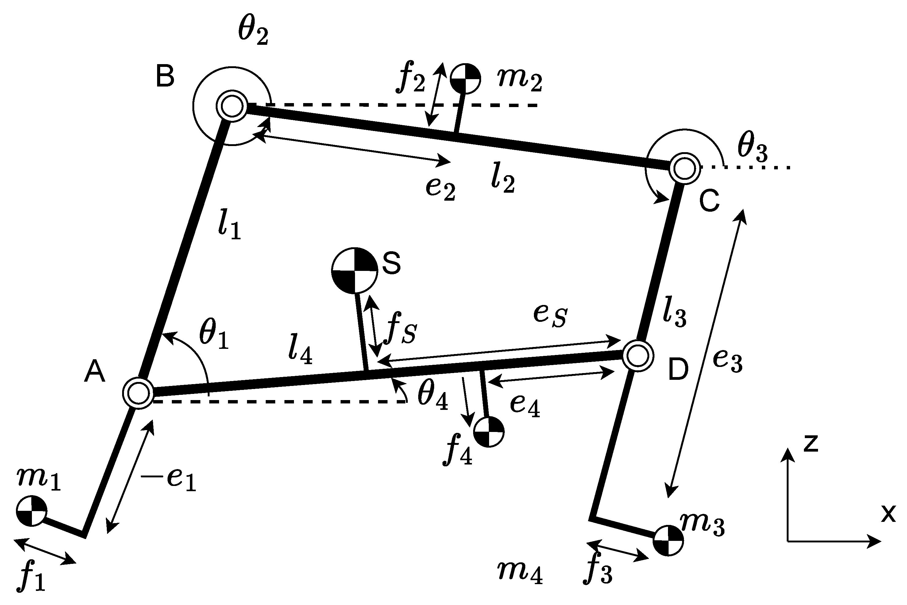
Mechanisms consisting of four-, five-, and six-bar closed-chain linkages have been extensively explored in the literature. The force balance conditions for a four-bar linkage were first explored by Berkof and Lowen [15] and subsequently expanded to moment balance in [16]. These conditions were further analyzed to determine feasible designs in [74,75,76]. A theoretical example of a 1-DOF force-balanced four-bar linkage, as presented by [75], is shown in Figure 9. The detailed design of the linkage profile itself, using topology optimization to achieve dynamic balancing, is presented in [77,78].
The force and moment balance conditions of 2–4 closed chains of three successive serial revolute joints (RRR) were derived by van der Wijk [21]. A method of determining a partially dynamically balanced five-bar linkage was also analyzed using optimization methods for zero reaction torques [79]. An analysis of the counter mass design considerations for force and moment balancing was presented by Arakelian [80].
Most of the mechanisms outlined above have only been balanced in the case of planar systems, and building spatial systems requires synthesizing planar mechanisms into a spatial arrangement, which is further elaborated on in Section 3.4. An approach that designs dynamically balanced mechanisms in 3D using Parallel-Pipeds and finding spatial balance conditions has been explored by Gosselin and Wu [81,82]. These designs typically require very large mass additions and are only feasible for ground-based manipulators.
The dynamic balance of flexible four-bar linkages is a topic of interest, as four-bar linkages are a common closed-chain mechanism used for industrial automation purposes. In [83], the dynamic equations are modeled using cubic spline functions for beam discretization. The authors found that the counter masses/inertias attached to inherently balance such a mechanism are the dominant factor in vibrations.
Kalas [84] investigated the dynamic balance of a five-bar linkage with a single compliant flexible link by modeling the links as pseudo-rigid. Meijaard and van der Wijk [26] presented two approaches to the dynamic balance of flexible link mechanisms: (1) the similarity of a mechanism and a balancing mechanism, and (2) modal balancing, where the lowest-order linear vibration modes suppress the shaking forces and moments, according to the material properties of the link structure. These can be classified under inherent balancing, as the combined dynamic behavior of the system is optimized for dynamic balance, which now includes the material properties of the links. According to their analysis, for flexible mechanisms, there is a trade-off between force balance and moment balance.

3.3.2. Principal Vector Method

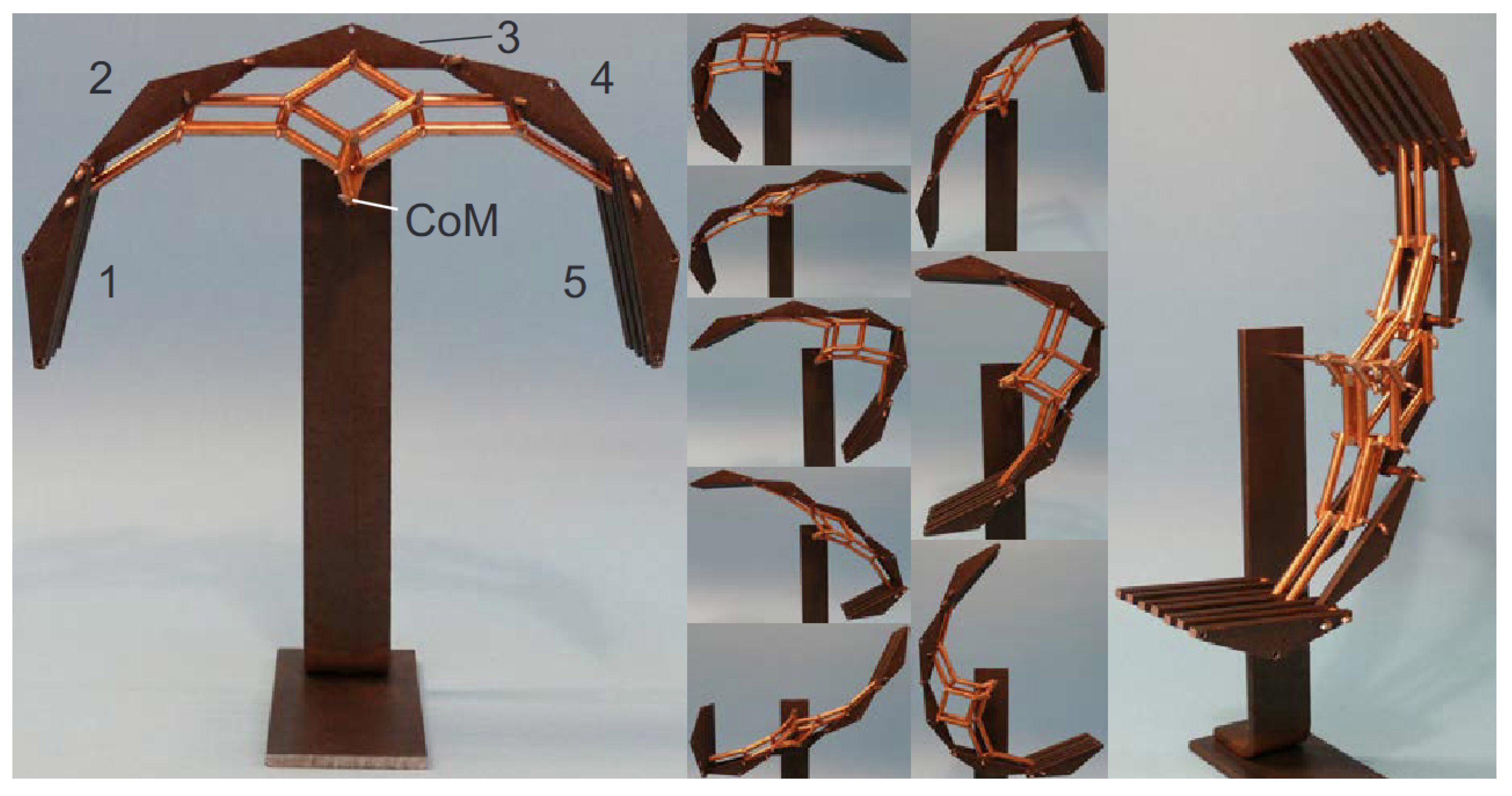
A simplification of the equations of motion for a complex mechanism consisting of multiple links aligned with a set of principal axes was derived by Otto Fischer for biomechanics [13], called the Principal Vector method. The Fischer method reformulates the motion of the centers of mass of linkages along coordinate bases aligned with their principal axes. This was later generalized by van der Wijk to multiple closed loops [85,86]. It has been extensively applied to the design of force and moment balanced mechanisms [21]. An example of a 4-DOF mechanism developed from the proposed designs is shown in Figure 10.
The most common implementation of the Principal Vector approach is to balance parallelogram [87] and pantograph-based manipulators that require lower mass additions compared to other parallel mechanisms [10,52,53,69]. Pantograph designs are also used as a form of balancing ALM for mechanisms [19,51]. While the majority of balanced pantograph designs are planar configurations, van der Wijk [88] has extended them to spatial mechanisms.
Often, multiple DOF mechanisms resulting from principal vector designs can be complex to implement in practice. Girgenti and van der Wijk [89] present methods of substituting complex kinematic designs with passive components in order to simplify the design and conserve space.

3.4. Synthesis

The inherent balancing approach for designing dynamically balanced mechanisms (Section 3.3) provides a powerful tool for designing balanced one or more degrees of freedom (DOF) planar mechanisms. Combining lower-DOF balanced mechanisms into kinematic arrangements of higher DOF and more complex balanced manipulators, both planar and spatial, is a popular and mature approach explored extensively in this field.
While synthesized mechanisms allow for easier design of high DOF manipulators, these designs are often not optimal in terms of mass and inertia addition. In that case, closed-loop constraints are used to find further balance conditions in order to reach the optimal balanced design [87].
Synthesis has been applied extensively for parallel mechanisms [90], pantographs [91], and designs with both inherent balance properties and added passive components [59]. Jean and Gosselin [92] presented an approach for synthesizing 1–3 DOF planar manipulators from statically balanced four-bar linkages and further applied an inherent balancing approach to derive balance conditions [92].
Gosselin then extended this approach to synthesize force and moment balanced four-bar linkage mechanisms into 2–6 DOF dynamically balanced planar and spatial mechanisms [75,76,93]. The four-bar linkages either jointly balance a load at an end-effector or are stacked on top of each other with recursive balancing of four-bar linkages through a chain, as shown in Figure 11.
More than one balancing approach can also be synthesized to design a balanced mechanism. Auxiliary parallelograms and springs have been employed in [17,94] and studied at a conceptual level in [95] to achieve gravity balancing for a spatial manipulator. A patent [96] describes a balance mechanism synthesizing a parallelogram ALM, a spring-loaded cam assembly, and a constant force spring for the static balancing of robot auxiliary equipment.
The force and moment balance conditions of serial three revolute joint (RRR) planar manipulators were derived by van der Wijk [21], which were then synthesized to design a variety of planar 2–4 DOF force-balanced mechanisms [97]. In this case, the inherent dynamic balancing conditions of the synthesized mechanisms were derived using the closed-loop conditions, thereby further reducing the mass and inertial addition.
In some cases, moment balance conditions are too restrictive to implement in practice for designing a manipulator. In that case, a hybrid approach of mechanical design and control is adopted. The set of dynamic motion conditions for moment-balanced trajectories are derived, and trajectories are selected to be along or close to these reactionless trajectories or paths. Papadopoulos and Abu-Abed [98] designed a nine-bar finger mechanism for space manipulation that is dynamically balanced through a combination of dynamic parameter changes and finding reactionless paths. Ouyang et al. [99] propose the Adjusted Kinematic Parameter (AKP) method, which force-balances a five-bar mechanism in conjunction with real-time Proportional-Derivative control. A hybrid mechanical-design and control approach for balancing a 3-RRR manipulator was presented in [100]. van der Wijk et al. [97] designed and experimentally validated a 4-RRR parallel mechanism that uses inherent balancing and optimal trajectories along reactionless paths for dynamic balancing.
Synthesized mechanisms are the predominant method by which experimental manipulator prototypes have been built and tested for force balance (e.g., PAMINSA [101]) and dynamic balance (e.g., DUAL-V [97]). A summary, along with a detailed elaboration of these mechanisms, is given in Section 4.

3.5. Summary and Comparison of Approaches

Previous subsections (Section 3.1, Section 3.2, Section 3.3 and Section 3.4) showed all the possible approaches to design balanced manipulators. These approaches are not mutually exclusive, and many proposed designs combine a variety of these approaches. The methods described, along with their advantages, disadvantages, and relevant papers, are summarized and compared in Table 1.

4. Experimental Prototypes

The overwhelming majority of research in the field of dynamic balancing is theoretical, and even application papers are mostly validated in simulation. We identified 23 papers in the literature that present physically built and validated balanced manipulator prototypes with experimental results. These are elaborated on in the following subsections and summarized in Table 2.

4.1. Gravity Balanced

The earliest example of a balanced manipulator prototype is by Ulrich and Kumar [119], who gravity balanced a 1- and 2-DOF link manipulator through a spring connected with a pulley system.
Agrawal et al. [87] then developed the next instance of an experimental prototype, a gravity-balanced 3-DOF serial manipulator. The center of mass was identified by balancing the manipulator using auxiliary parallelograms, which was then balanced using a single actively driven counter mass. The actual center of mass closely tracked the desired as extrapolated from the dynamic model and joint encoder angles.
Spring-based gravity compensation methods have been prototyped by several different researchers. Cho et al. [120] presented a 2-DOF spring-based gravity balancing mechanism for a link with roll and pitch motion, operating in a hemispheric workspace. A spring-based balancing mechanism was employed for the gravity balancing of a 3-DOF Prismatic-Revolute-Revolute manipulator by [42]. Using a different number of coil loops for the wire that connects the spring successively to all the joints, the mechanism ensured static balance and joint torque reduction rates of 61–90%.
Most recently, a spring cam mechanism was developed to balance a serial 3-DOF planar manipulator [121]. The mechanism attaches to the base and connects to the links via pulley mechanisms with calculated force factor reductions between the links, so that the manipulator is balanced with a single spring.
For gravity-balancing spatial manipulators, Baradat et al. [38] developed a method of gravity balancing a 3-DOF Delta robot using a pantograph mechanism that was actuated with a control law to provide a balancing force at the end-effector. This method is preferable to mass additions or springs, as it can also adjust for different loads applied at the end-effector. The mechanism also reduces precision errors caused by deformations of the manipulator that lead to misalignment of the end-effector due to changes in altitude and inclination.
They tested their concept on an experimental prototype built by modifying the SurgiScope(R), a robotized navigation tool holder. The results showed a reduction in the root mean square value of the input torque by 99.5% and a significant reduction in the position errors, from 86.8% to 97.5%.

4.2. Statically Balanced Manipulators

The most basic application of static balancing is 1-DOF displacement of a battery to offset the horizontal (i.e., gravity orthogonal) center of mass displacement of an aerial manipulator by Ruggiero et al. [6]. Al Akhras et al. [64] improve this to a lightweight arm powered by pulleys, concentrating the mass near the mount and optimizing the link profiles, which require smaller battery displacements. Luxton et al. [66] statically balanced a 2-DOF manipulator with a separate active counter mass attached to the manipulator. It has a mass of 312 g, of which 90 g is the counter mass for a payload of 30 g.
In all of these cases, the aerial manipulator exhibited lower base displacements with static balancing, which also improved the base stability. An experimental prototype of this simple static balancing concept is shown in Figure 12.
A statically balanced 4-DOF robot arm mimicking a human shoulder and elbow using a parallelogram structure and springs was presented by Vermeulen and Wisse [122]. It was tested in a pick-and-place operation with a 2 kg mass over 0.8 m in 1.5 s, using a small 1.5 W DC motor assisted by balanced behavior.
A statically balanced aerial manipulator was developed by Imanberdiyev et al. [108] using 2 lightweight 6-DOF arms, which can be operated in multiple modes for different tasks. In one of the modes, one of the arms conducted the manipulation task while the other balanced the center of mass of the overall system using control-based methods. This can be categorized as an ALM approach, as it is a duplicate mechanism. The balancing behavior for the balanced manipulation was validated in an experiment by measuring base motions.
An aerial manipulator that, in addition to static balancing, also attempted moment balancing was presented by Ohnishi et al. [65]. By kinematically constraining a joint, the angular momentum of the 2-DOF manipulator remains the same for all motions of the first joint. The authors tested their design in a live aerial manipulation scenario and found that the attitude disturbances were reduced when the sliding battery balancing mechanism was activated.
A statically balanced manipulator consisting of synthesizing legs of a pantograph and spring-pulley system was designed by Ebert-Uphoff and Johnson [39]. Laliberte et al. [35] designed a prototype of a 3-DOF parallel manipulator using a parallelogram that is statically balanced with counterweights and springs. In both of these papers, they display a prototype, but the results provided are purely from simulation.

4.3. Force-Balanced Manipulators

Counter mass-based force balancing of an industrial PUMA-760 serial manipulator was attempted early in the development of this field [103]. The mass increase is significant, with over 100 kg added to a link to balance a 5 kg payload.
A force-balanced Delta robot, designed by modifying each arm into a pantograph and balancing it with counter masses, was formulated by van der Wijk and Herder [69] and prototyped by Clark et al. [52] for aerial manipulation applications. The results showed a reduction in shaking forces and moments; however, the improvement in precision was not significant.
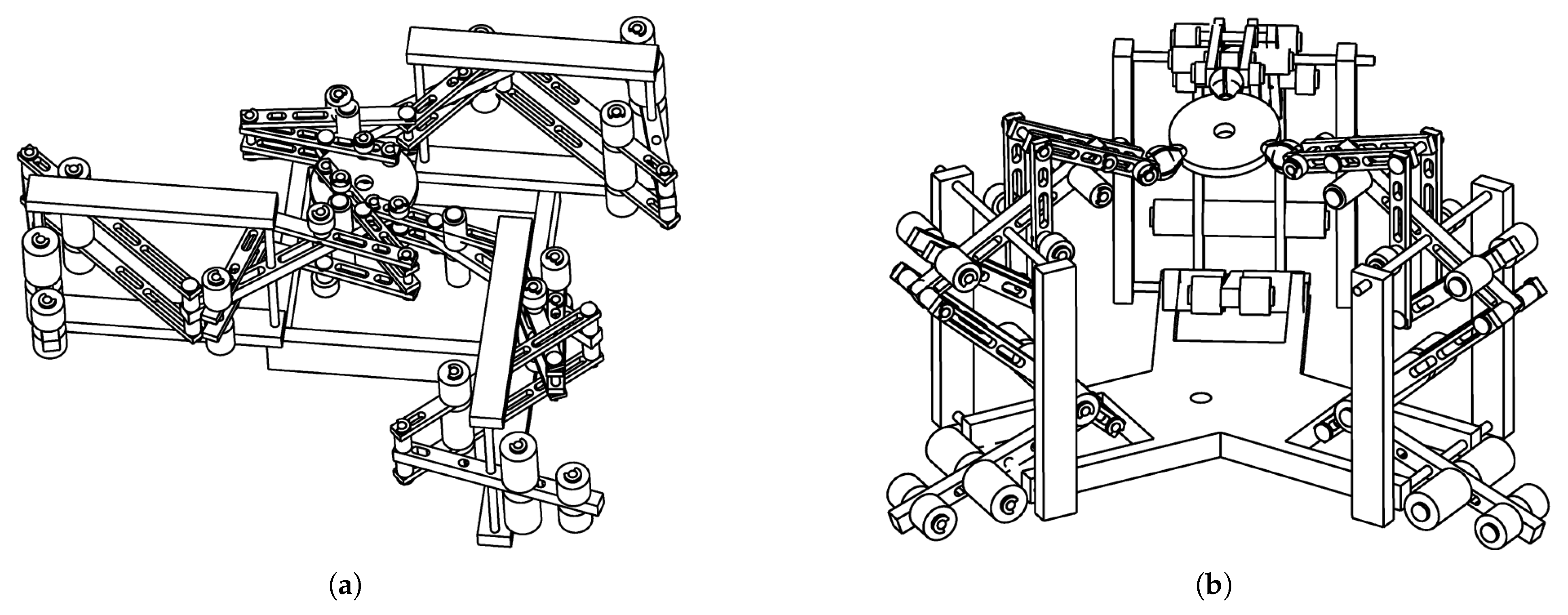
Similar to [52], a force-balanced pantograph was synthesized as a 3-DOF spatial manipulator by Suryavanshi et al. [53,125], with its kinematic configuration similar to that of a Delta robot. It allows operation in two modes similar to the DYMO parallel robot [126]: a translation mode and rotation mode, which is based on the different joint angle combinations within domains bounded by singular configurations. Force sensors arranged parallel and perpendicular to gravity on the base validate the force balance by measuring reaction forces, which are of a small magnitude of up to 0.2 N. The manipulator is shown in Figure 13.
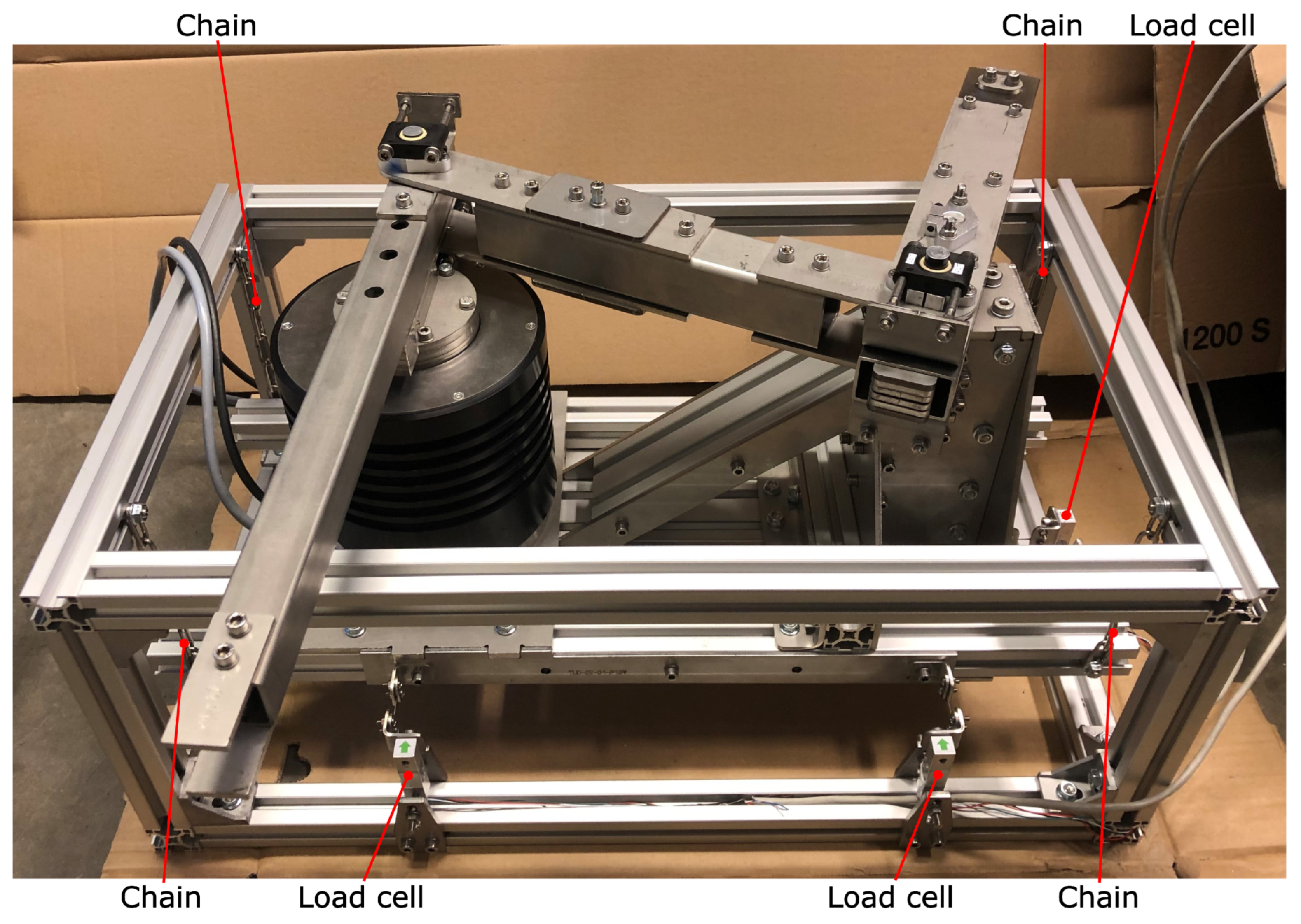
An advancement in the techniques of synthesizing force-balanced mechanisms was developed as the PAMINSA manipulator family (Figure 14). Briot et al. [101] presented a methodology to design force-balanced pantograph legs from various combinations of revolute (R) and prismatic (P) joint kinematic chains. These pantograph legs are then synthesized to form 3 to 6 DOF spatial manipulators based on different kinematic configurations. The force-balanced counter masses as well as reduced “partially balanced” counter mass which result in minimal reaction torques for desired high-acceleration trajectories were calculated. The built prototype of a 4-DOF manipulator synthesized from 3 Revolute-Prismatic-Revolute (RPR) chains was tested with and without a 200 N load. The partially balanced manipulator has 79% of the mass of the when fully counter mass balanced, yet has the same reduced joint torques while manipulating a 200 N load compared to an unbalanced manipulator. A further simulation study [48] investigated dynamic balancing using rotation of the wrist to counteract reaction torques.

4.4. Dynamically Balanced Manipulators

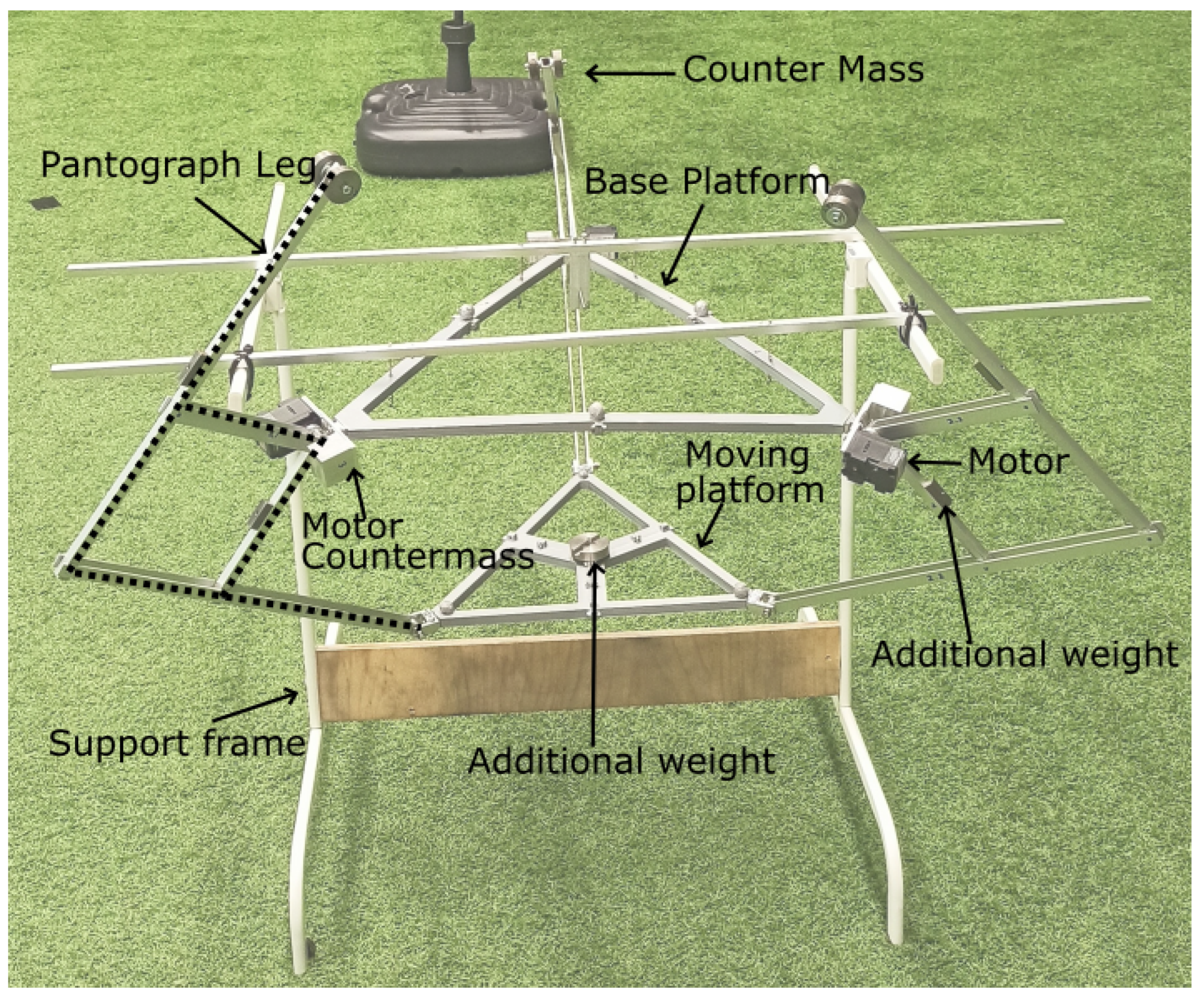
A dynamically balanced four-bar linkage manipulator designed with an inherent balancing approach was built by Zomerdijk et al. [118] and achieved up to 21G tip accelerations, 99.3% reduction in reaction forces, and 97.8% reduction in reaction moment. A structural analysis for the finite element model was also performed to address in-plane and out-of-plane deformation for the first three modes, addressing issues from flexible body behavior which degrades the precision. The manipulator is shown in Figure 15.
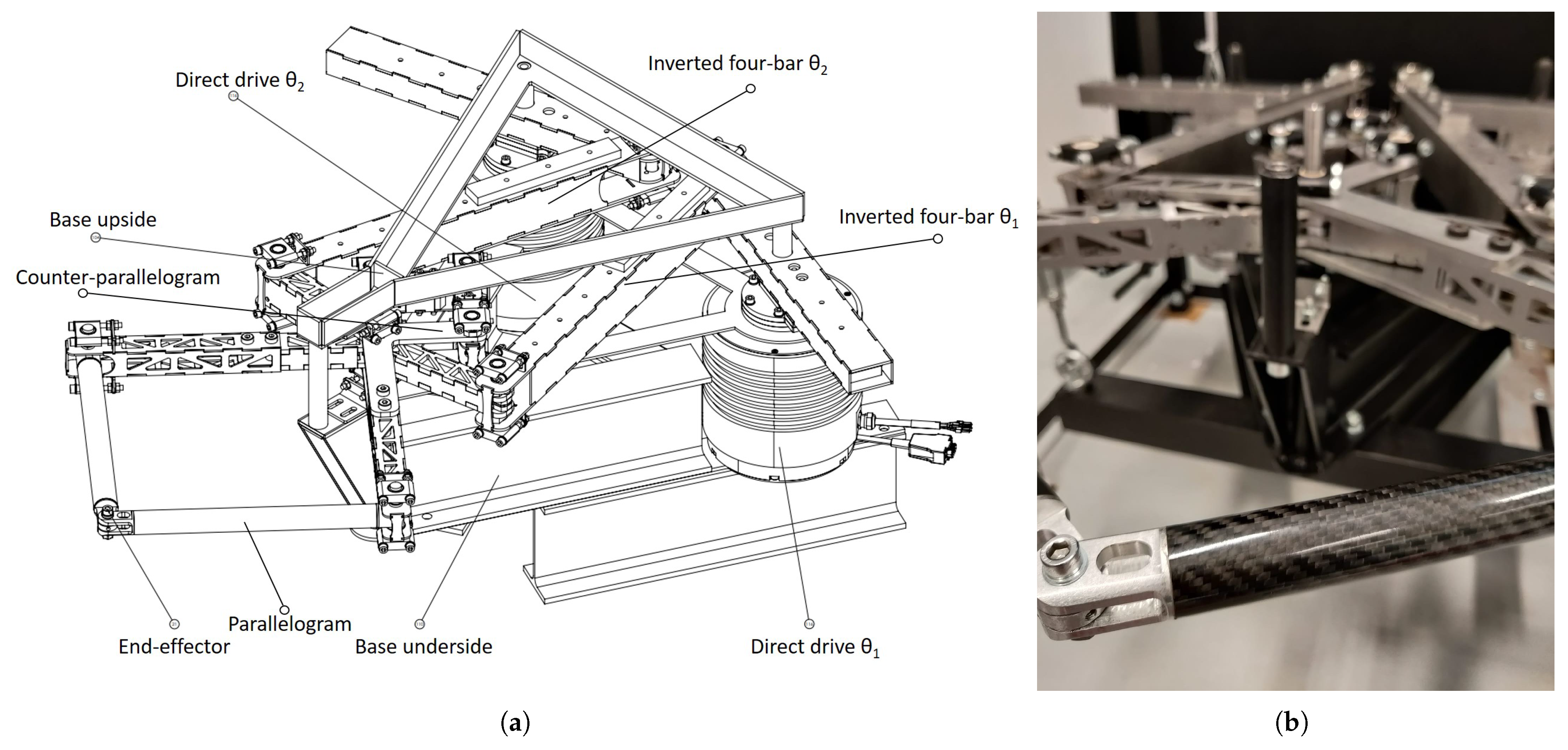
This was extended to a 2-DOF planar mechanism, where a parallelogram manipulator is dynamically balanced with a counter parallelogram [123]. The manipulator parallelogram is extended using inverted four-bar linkages that add stiffness and rigidity, and contain the actuating joints. The reaction force was reduced by 93.6% and reaction moment by 88.9%, reaching up to 3G acceleration in experiments. A finite element analysis was also conducted to analyze the degradation of performance due to flexible body deformations. However, the balancing modifications required a mass 9.9 times and inertia roughly 4 times that of the unbalanced manipulator. This manipulator, called Super-B, is shown in Figure 16, and has been patented [127].
Bom [128] attempted to design and prototype a 2-DOF manipulator synthesized with 2 four-bar linkages suitable for aerial manipulation; however, further work is required to fully validate moment balancing behavior.
Two parallelogram mechanisms were synthesized to create a 3-DOF planar manipulator that is force-balanced and moment balanced for certain trajectories [129]. Dynamic balancing was verified using tracking the displacement of a point on the base, which was below 1 mm for the balanced mechanism and up to 12 mm for the unbalanced.
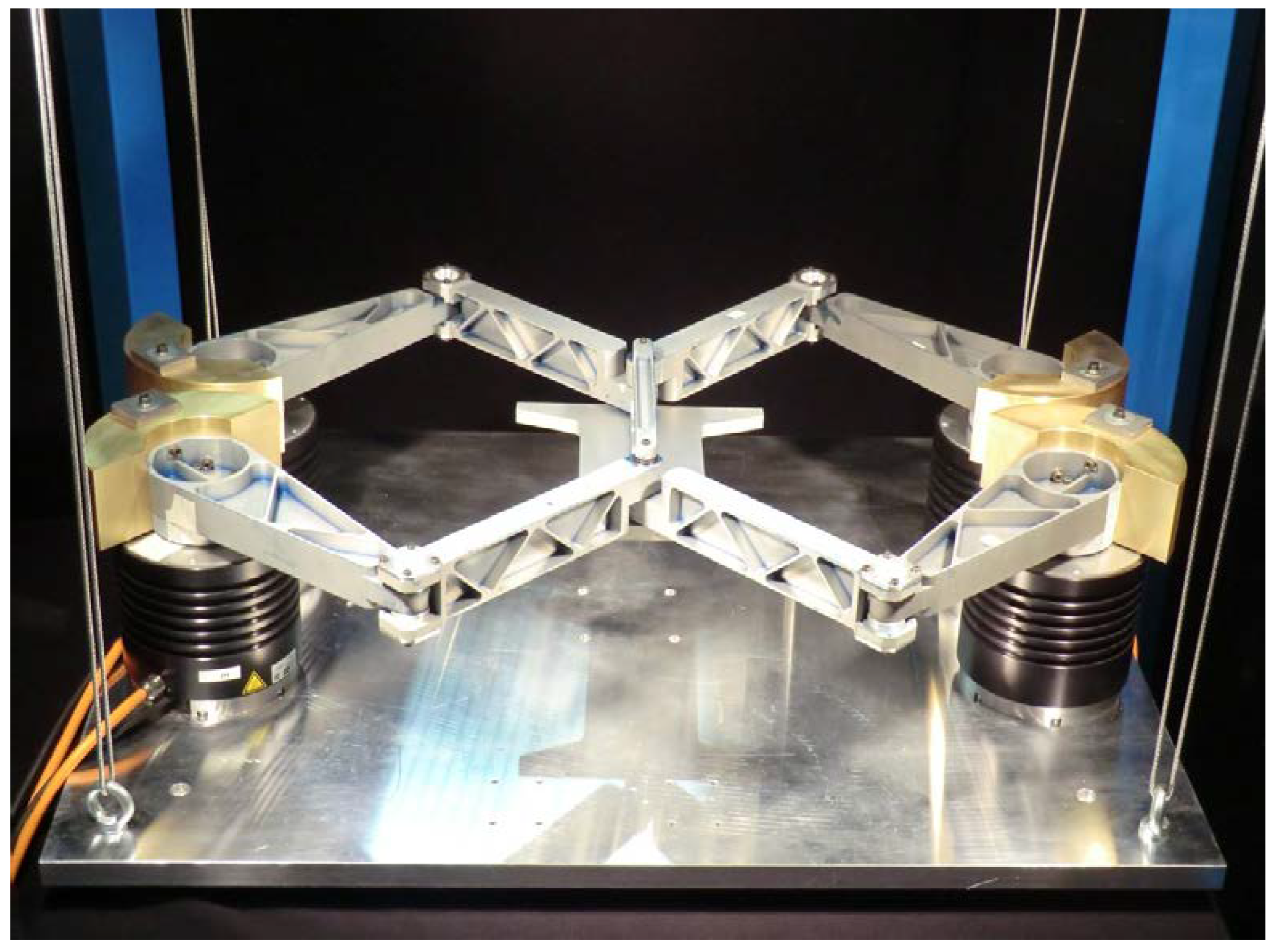
A 4-DOF planar dynamically balanced manipulator, designed from inherently balancing 4-RRR 2-DOF serial chains (DUAL-V), was prototyped, tested in [21,97], and patented [130]. The manipulator is force-balanced for all translational motions of the platform, and moment balanced for motion along the reactionless paths along central axes. The manipulator achieved 93–97% reduction in shaking forces and up to 96% reduction in shaking moments for reactionless trajectories, with a maximum acceleration of 10.3G. Due to the increase in inertia, for high-acceleration applications the actuator joint torques are increased 47% higher than those for the unbalanced manipulator. The manipulator is shown in Figure 17.
Laliberte and Gosselin [59] prototype 3 different types of passive component additions that dynamically balance a 2-DOF parallel mechanism: a CR to result in a constant inertia, proximal CM/CI, and an ALM balancing pantograph. The comparison showed that balancing greatly reduced reaction torques and forces, as well as joint torques. However, there is a up to 5-fold mass/inertia addition involved with dynamic balancing, and a trade-off between decreasing mass and increasing inertia relating to the space occupied by components.
Finally, a Delta arm was balanced using an ADBU by Mirz et al. [109]. The balancing unit had two translational and one rotational DOF, and controlled for shaking forces and moments using (1) open-loop control based on the manipulator dynamic model and (2) closed-loop control using independent modal space control. The results found that the maximal vibration amplitude in the principal direction of motion can be reduced up to 86%.
The experimental prototypes discussed in this section are summarized in Table 2. Only research papers which demonstrate real-world experimental results validated through metrics are included. We categorize in the following order: type of balancing, dimension (planar or spatial), number of spatially balanced DOF, and end-effector motion DOF. We differentiate the latter 2 columns as often manipulators have higher motion DOF, of which a subset are balanced, or vice versa, where the dimensionality of balanced DOF is greater than the DOF determining the motion of the end effector. For example, a dynamically balanced 2-DOF manipulator is force-balanced in 2 Cartesian dimensions and moment balanced orthogonal to the plane, while only having 2-DOF motion that can uniquely determine the Cartesian position of the end effector. A summary of the method, experimental metrics, and the citation for every paper is also included.

5. Conclusions

In the past few decades, balanced manipulators have seen many advancements, starting from theoretical contributions that are now being implemented as real-world prototypes. They offer many advantages for both ground-fixed and mobile robot manipulation, where disturbances pose a problem for precise and robust task execution.
The scope of theoretical designs is wide due to the variety of methods available; however, the feasibility of implementing these in practice reduces that scope. The various design approaches can be selected based on the task and environment for the manipulator, which will determine the requirements and tradeoffs in area, mass/inertia, and maneuverability.
At a fundamental level, approaches to designing balancing manipulators involve adding passive or active components, or inherent balancing based on adjusting the geometric, kinematic, and dynamic parameters. Low DOF balanced manipulators designed using these approaches can also be synthesized into complex higher DOF manipulators.
While theoretical contributions to this field are prolific, real-world applications remains in their infancy. We identified 23 experimental prototypes of real-world balanced systems that have been built and tested in experimental scenarios. The validated results show that balancing robotic manipulators results in smaller base displacements, higher maximum accelerations, and lower maximum joint torques during the execution of manipulation tasks. However, this often results in a significant tradeoff in terms of mass/inertia or area increase.

Challenges and Future Work

Balanced manipulator designs often result in infeasibly high masses, mass/inertia values that are difficult to achieve in practice, or a large increase in workspace that is not feasible in a constrained industrial automation factory floor or on a mobile robot. Perhaps for this reason, we could not find any attempts to build an inherently designed experimental spatial manipulator prototype with dynamic balance.
Designing for highly accurate mass and inertia of links restricts the scope of designs and also requires very precise fabrication of parts. The balance conditions for many inherently balanced designs are often highly sensitive to parameter errors. While the mass of links can be easily adjusted using adjustable counter masses, achieving precise inertias for dynamic balance requires high-quality machining.
The increase in mass/inertia of manipulators from force/moment balancing modifications also increases the inertial moments; hence, the joint torques also increase for higher accelerations, overcoming any improvements from the reduction in gravity compensation. In such cases, a tradeoff analysis for improvement in precision vs. increase in joint torques [101] or a hybrid mechanical design and optimal trajectory control approach [28,97,100] is more suitable.
Control-based approaches or ADBU units can also reduce shaking forces and moments without significant mass or inertial addition, which makes them a preferred option over mechanical design approaches. For these reasons, force balance remains the more feasible and, hence, preferred type of balancing for prototyped manipulators, spanning a variety of planar and spatial designs.
There are several challenges to overcome and promising directions that offer ample research opportunities, as well as commercial applications:
  • Continued research in designing, building, and experimentally validating physical prototypes of abstract design concepts for real world applications. These will provide more examples for researchers on the practical issues involved in the design and manufacturing of balanced manipulators.
  • Analysis and comparison of the practical mechanical implementation of abstract components (such as CRCM, ADBU, etc.) that comply with the design constraints inherent in real-world manipulator designs.
  • More research into the design of low-mass and low-inertia components from a mechanical perspective, as mass and inertia increase poses a major challenge to the practical implementation of balanced manipulators in mobile platforms.
  • Synthesis of mechanical design and control approaches for dynamic balancing. This idea was proposed in [28] and explored in some other studies. Control approaches have been extensively explored in the field of space manipulators [18]. However, real-world experimental results remain sparse in the literature. Designing dynamic balanced manipulators can be very difficult in practice; however, a synthesis of force balancing and control along reactionless trajectories can achieve this objective without requiring complex and precise designs.
We anticipate that in the years to come, research on balanced robotic manipulators will continue to develop. These advances, particularly when accompanied with experimental prototypes, will show the improved benefits of balanced manipulators for many manipulation tasks and pave the way for increased commercial application.

Author Contributions

Conceptualization, S.C.; methodology, S.C., Y.J.V. and V.v.d.W.; formal analysis, Y.J.V.; investigation, Y.J.V.; resources, S.C.; data curation, Y.J.V.; writing—original draft preparation, Y.J.V.; writing—review and editing, Y.J.V., S.C., and V.v.d.W.; visualization, Y.J.V.; supervision, S.C.; project administration, S.C.; funding acquisition, S.C. All authors have read and agreed to the published version of the manuscript.

Funding

The research leading to these results has received funding from the European Union’s Horizon 2020 research and innovation program under the Marie Sklodowska-Curie grant agreement no 101034319 and from the European Union—NextGenerationEU. Part of this work was carried out in the framework of the project “DynAeRobot—Development and validation of a new dynamically balanced aerial manipulator” (project no. BIRD213590), funded under the BIRD 2021 program promoted by the University of Padova.

Data Availability Statement

No new data was created or analyzed in this study. Data sharing is not applicable to this article. For the relevant data in the cited works, please contact the authors.

Acknowledgments

We thank Marco Tognon (Principal Investigator, INRIA Rennes), for his valuable guidance and input in this research.

Conflicts of Interest

The authors declare no conflicts of interest.

Abbreviations

The following abbreviations are used in this manuscript:
ADBUActive Dynamic Balancing Unit
ALMAdditional Linkage Mechanism
DCDirect Current
DOFDegree of Freedom
CICounter Inertia
CMCounter Mass
CRCounter Rotation
CRCMCounter Rotating Counter Mass
GGravitational-Force equivalent
PIDProportional-Integral-Derivative (Control)
RRRRevolute-Revolute-Revolute

References

  1. Ghodsian, N.; Benfriha, K.; Olabi, A.; Gopinath, V.; Arnou, A. Mobile Manipulators in Industry 4.0: A Review of Developments for Industrial Applications. Sensors 2023, 23, 8026. [Google Scholar] [CrossRef]
  2. Billard, A.; Kragic, D. Trends and challenges in robot manipulation. Science 2019, 364, eaat8414. [Google Scholar] [CrossRef] [PubMed]
  3. Thakar, S.; Srinivasan, S.; Al-Hussaini, S.; Bhatt, P.M.; Rajendran, P.; Jung Yoon, Y.; Dhanaraj, N.; Malhan, R.K.; Schmid, M.; Krovi, V.N.; et al. A Survey of Wheeled Mobile Manipulation: A Decision-Making Perspective. J. Mech. Robot. 2022, 15, 020801. [Google Scholar] [CrossRef]
  4. Aldhaheri, S.; De Masi, G.; Pairet, E.; Ardón, P. Underwater Robot Manipulation: Advances, Challenges and Prospective Ventures. In Proceedings of the OCEANS 2022, Chennai, India, 21–24 February 2022; pp. 1–7. [Google Scholar] [CrossRef]
  5. Ollero, A.; Tognon, M.; Suarez, A.; Lee, D.; Franchi, A. Past, Present, and Future of Aerial Robotic Manipulators. IEEE Trans. Robot. 2022, 38, 626–645. [Google Scholar] [CrossRef]
  6. Ruggiero, F.; Trujillo, M.; Cano, R.; Ascorbe, H.; Viguria, A.; Peréz, C.; Lippiello, V.; Ollero, A.; Siciliano, B. A multilayer control for multirotor UAVs equipped with a servo robot arm. In Proceedings of the 2015 IEEE International Conference on Robotics and Automation (ICRA), Seattle, WA, USA, 26–30 May 2015; pp. 4014–4020, ISSN 1050-4729. [Google Scholar] [CrossRef]
  7. Khamseh, H.B.; Janabi-Sharifi, F.; Abdessameud, A. Aerial manipulation—A literature survey. Robot. Auton. Syst. 2018, 107, 221–235. [Google Scholar] [CrossRef]
  8. Papadopoulos, E.; Aghili, F.; Ma, O.; Lampariello, R. Robotic Manipulation and Capture in Space: A Survey. Front. Robot. AI 2021, 8, 686723. [Google Scholar] [CrossRef] [PubMed]
  9. Gosselin, C. Gravity Compensation, Static Balancing and Dynamic Balancing of Parallel Mechanisms. In Smart Devices and Machines for Advanced Manufacturing; Springer: London, UK, 2008; Chapter 2; pp. 27–48. [Google Scholar] [CrossRef]
  10. Arakelian, V. Inertia forces and moments balancing in robot manipulators: A review. Adv. Robot. 2017, 31, 717–726. [Google Scholar] [CrossRef]
  11. van der Wijk, V.; Krut, S.; Pierrot, F.; Herder, J. Generic Method for Deriving the General Shaking Force Balance Conditions of Parallel Manipulators with Application to a Redundant Planar 4-RRR Parallel Manipulator. In Proceedings of the IFToMM 2011 World Congress: The 13th World Congress in Mechanism and Machine Science, Guanajuato, Mexico, 19–25 June 2011; p. A12. [Google Scholar]
  12. Lim, T.G.; Cho, H.S.; Chung, W.K. Payload capacity of balanced robotic manipulators. Robotica 1990, 8, 117–123. [Google Scholar] [CrossRef]
  13. van der Wijk, V.; Herder, J.L. The Work of Otto Fischer and the Historical Development of His Method of Principal Vectors for Mechanism and Machine Science. In Explorations in the History of Machines and Mechanisms; History of Mechanism and Machine Science; Koetsier, T., Ceccarelli, M., Eds.; Springer: Dordrecht, The Netherlands, 2012; pp. 521–534. [Google Scholar] [CrossRef]
  14. Lowen, G.G.; Berkof, R.S. Survey of investigations into the balancing of linkages. J. Mech. 1968, 3, 221–231. [Google Scholar] [CrossRef]
  15. Berkof, R.S.; Lowen, G.G. A New Method for Completely Force Balancing Simple Linkages. J. Eng. Ind. 1969, 91, 21–26. [Google Scholar] [CrossRef]
  16. Berkof, R.S. Complete force and moment balancing of inline four-bar linkages. Mech. Mach. Theory 1973, 8, 397–410. [Google Scholar] [CrossRef]
  17. Agrawal, S.K.; Fattah, A. Gravity-balancing of spatial robotic manipulators. Mech. Mach. Theory 2004, 39, 1331–1344. [Google Scholar] [CrossRef]
  18. Agrawal, S.K.; Fattah, A. Reactionless space and ground robots: Novel designs and concept studies. Mech. Mach. Theory 2004, 39, 25–40. [Google Scholar] [CrossRef]
  19. Arakelian, V.H.; Smith, M.R. Shaking Force and Shaking Moment Balancing of Mechanisms: A Historical Review with New Examples. J. Mech. Des. 2005, 127, 334–339. [Google Scholar] [CrossRef]
  20. Kochev, I.S. General theory of complete shaking moment balancing of planar linkages: A critical review. Mech. Mach. Theory 2000, 35, 1501–1514. [Google Scholar] [CrossRef]
  21. van der Wijk, V. Methodology for Analysis and Synthesis of Inherently Force and Moment-Balanced Mechanisms. Ph.D. Thesis, University of Twente, Enschede, The Netherlands, 2014. [Google Scholar] [CrossRef]
  22. Wei, B.; Zhang, D. A Review of Dynamic Balancing for Robotic Mechanisms. Robotica 2020, 39, 55–71. [Google Scholar] [CrossRef]
  23. Arakelian, V.; Briot, S. Balancing of Linkages and Robot Manipulators; Number v.27 in Mechanisms and Machine Science Ser.; Springer International Publishing AG: Cham, Swizerland, 2015. [Google Scholar]
  24. Lee, S.; Cho, H.S. Dynamic characteristics of balanced robotic manipulators with joint flexibility. Robotica 1992, 10, 485–495. [Google Scholar] [CrossRef]
  25. Yu, Y.Q.; Lin, J. Active Balancing of a Flexible Linkage with Redundant Drives. J. Mech. Des. 2003, 125, 119–123. [Google Scholar] [CrossRef]
  26. Meijaard, J.P.; van der Wijk, V. Dynamic balancing of mechanisms with flexible links. Mech. Mach. Theory 2022, 172, 104784. [Google Scholar] [CrossRef]
  27. Yu, Y.Q.; Jiang, B. Analytical and experimental study on the dynamic balancing of flexible mechanisms. Mech. Mach. Theory 2007, 42, 626–635. [Google Scholar] [CrossRef]
  28. Papadopoulos, E.; Abu-Abed, A. On the Design of Zero Reaction Manipulators. J. Mech. Des. 1996, 118, 372–376. [Google Scholar] [CrossRef]
  29. Huang, P.; Xu, Y.; Liang, B. Dynamic Balance Control of Multi-Arm Free-Floating Space Robots. Int. J. Adv. Robot. Syst. 2005, 2, 13. [Google Scholar] [CrossRef]
  30. Vukobratovic, M.; Borovac, B. Dynamic balance concept and the maintenance of the dynamic balance in humanoid robotics. In Proceedings of the International Symposium on Intelligent Systems and Informatics (SISY), Subotica, Serbia, 26–27 September 2008; pp. 1–11, ISSN 1949-0488. [Google Scholar] [CrossRef]
  31. Huang, Y.; Bing, Z.; Zhang, Z.; Zhuang, G.; Huang, K.; Knoll, A. Optimizing Dynamic Balance in a Rat Robot via the Lateral Flexion of a Soft Actuated Spine. In Proceedings of the IEEE International Conference on Robotics and Automation, Yokohama, Japan, 13–17 May 2024; pp. 3442–3448. [Google Scholar] [CrossRef]
  32. Li, Z.; Ge, Q.; Ye, W.; Yuan, P. Dynamic Balance Optimization and Control of Quadruped Robot Systems with Flexible Joints. IEEE Trans. Syst. Man Cybern. Syst. 2016, 46, 1338–1351. [Google Scholar] [CrossRef]
  33. Arakelian, V. Gravity compensation in robotics. Adv. Robot. 2016, 30, 79–96. [Google Scholar] [CrossRef]
  34. Saravanan, R.; Ramabalan, S.; Dinesh Babu, P. Optimum static balancing of an industrial robot mechanism. Eng. Appl. Artif. Intell. 2008, 21, 824–834. [Google Scholar] [CrossRef]
  35. Laliberte, T.; Gosselin, C.; Jean, M. Static balancing of 3-DOF planar parallel mechanisms. IEEE/ASME Trans. Mechatronics 1999, 4, 363–377. [Google Scholar] [CrossRef]
  36. Gosselin, C.M.; Wang, J. Static balancing of spatial six-degree-of-freedom parallel mechanisms with revolute actuators. J. Robot. Syst. 2000, 17, 159–170. [Google Scholar] [CrossRef]
  37. Wang, J.; Kong, X. A geometric approach to the static balancing of mechanisms constructed using spherical kinematic chain units. Mech. Mach. Theory 2019, 140, 305–320. [Google Scholar] [CrossRef]
  38. Baradat, C.; Arakelian, V.; Briot, S.; Guegan, S. Design and Prototyping of a New Balancing Mechanism for Spatial Parallel Manipulators. J. Mech. Des. 2008, 130, 072305. [Google Scholar] [CrossRef]
  39. Ebert-Uphoff, I.; Johnson, K. Practical considerations for the static balancing of mechanisms of parallel architecture. Proc. Inst. Mech. Eng. Part K J. Multi-Body Dyn. 2002, 216, 73–85. [Google Scholar] [CrossRef]
  40. Quaglia, G.; Yin, Z. Static balancing of planar articulated robots. Front. Mech. Eng. 2015, 10, 326–343. [Google Scholar] [CrossRef]
  41. Lessard, S.; Bigras, P.; Bonev, I.A. A New Medical Parallel Robot and Its Static Balancing Optimization. J. Med. Devices 2007, 1, 272–278. [Google Scholar] [CrossRef]
  42. Lee, W.B.; Kim, D.W.; Song, J.B. Novel 3-DOF counterbalance mechanism based on spring balancer for mobile robot arms. Mechatronics 2022, 82, 102734. [Google Scholar] [CrossRef]
  43. Nguyen, V.L.; Lin, C.Y.; Kuo, C.H. Gravity compensation design of Delta parallel robots using gear-spring modules. Mech. Mach. Theory 2020, 154, 104046. [Google Scholar] [CrossRef]
  44. Bayer, A.; Bohlken, W.; Berninger, A. Vorrichtung zum Gewichtsausgleich eines Roboterarms. EP Patent EP1125696B1, 15 March 2006. [Google Scholar]
  45. Lin, P.Y.; Shieh, W.B.; Chen, D.Z. Design of Statically Balanced Planar Articulated Manipulators with Spring Suspension. IEEE Trans. Robot. 2012, 28, 12–21. [Google Scholar] [CrossRef]
  46. Juang, C.W.; Chen, D.Z. Spring Configurations and Attachment Angles Determination for Statically Balanced Planar Articulated Manipulators. J. Mech. Robot. 2022, 14, 054502. [Google Scholar] [CrossRef]
  47. Cho, C.; Kang, S. Design of a Static Balancing Mechanism for a Serial Manipulator with an Unconstrained Joint Space Using One-DOF Gravity Compensators. IEEE Trans. Robot. 2014, 30, 421–431. [Google Scholar] [CrossRef]
  48. Briot, S.; Bonev, I.A.; Gosselin, C.M.; Arakelian, V. Complete shaking force and shaking moment balancing of planar parallel manipulators with prismatic pairs. Proc. Inst. Mech. Eng. Part K J. Multi-Body Dyn. 2009, 223, 43–52. [Google Scholar] [CrossRef]
  49. van der Wijk, V.; Herder, J.L. Guidelines for Low Mass and Low Inertia Dynamic Balancing of Mechanisms and Robotics. In Advances in Robotics Research; Springer: Berlin/Heidelberg, Germany, 2009; pp. 21–30. [Google Scholar] [CrossRef]
  50. Chung, W.K.; Cho, H.S. On the Dynamics and Control of Robotic Manipulators with an Automatic Balancing Mechanism. Proc. Inst. Mech. Eng. Part B Manag. Eng. Manuf. 1987, 201, 25–34. [Google Scholar] [CrossRef]
  51. Russo, A.; Sinatra, R.; Xi, F. Static balancing of parallel robots. Mech. Mach. Theory 2005, 40, 191–202. [Google Scholar] [CrossRef]
  52. Clark, A.B.; Baron, N.; Orr, L.; Kovac, M.; Rojas, N. On a Balanced Delta Robot for Precise Aerial Manipulation: Implementation, Testing, and Lessons for Future Designs. In Proceedings of the 2022 IEEE/RSJ International Conference on Intelligent Robots and Systems (IROS), Kyoto, Japan, 23–27 October 2022; pp. 7359–7366. [Google Scholar] [CrossRef]
  53. Suryavanshi, K.; Hamaza, S.; van der Wijk, V.; Herder, J. ADAPT: A 3 Degrees of Freedom Reconfigurable Force Balanced Parallel Manipulator for Aerial Applications. In Proceedings of the 2023 IEEE International Conference on Robotics and Automation (ICRA), London, UK, 29 May–2 June 2023; pp. 11936–11942. [Google Scholar] [CrossRef]
  54. van der Wijk, V.; Herder, J.; Demeulenaere, B.; Gosselin, C. Comparative analysis and optimization for low-mass and low inertia dynamic balancing of a rotatable link balanced by a counter-mass. J. Mech. Robot. 2012, 4, 1–8. [Google Scholar] [CrossRef]
  55. van der Wijk, V.; Herder, J.L.; Demeulenaere, B. Comparison of Various Dynamic Balancing Principles Regarding Additional Mass and Additional Inertia. J. Mech. Robot. 2009, 1, 041006. [Google Scholar] [CrossRef]
  56. Feng, G. Complete shaking force and shaking moment balancing of 26 types of four-, five- and six-bar linkages with prismatic pairs. Mech. Mach. Theory 1990, 25, 183–192. [Google Scholar] [CrossRef]
  57. Baron, N.; Philippides, A.; Rojas, N. A Dynamically Balanced Kinematically Redundant Planar Parallel Robot. J. Mech. Des. 2021, 143, 083301. [Google Scholar] [CrossRef]
  58. van der Wijk, V.; Herder, J. Double Pendulum Balanced by Counter-Rotary Counter-Masses as Useful Element for Synthesis of Dynamically Balanced Mechanisms. In Proceedings of the IDETC/CIE 2008ASME 2008 International Design Engineering Technical Conferences & Computers and Information in Engineering Conference, Brooklyn, NY, USA, 3–6 August 2008; Volume 2, pp. 1–11. [Google Scholar] [CrossRef]
  59. Laliberté, T.; Gosselin, C. Synthesis, optimization and experimental validation of reactionless two-DOF parallel mechanisms using counter-mechanisms. Meccanica 2016, 51, 3211–3225. [Google Scholar] [CrossRef]
  60. van der Wijk, V.; Herder, J.L. Force balancing of variable payload by active force-balanced reconfiguration of the mechanism. In Proceedings of the 2009 ASME/IFToMM International Conference on Reconfigurable Mechanisms and Robots, London, UK, 22–24 June 2009; pp. 323–330. [Google Scholar]
  61. van der Wijk, V.; Andreff, N.; Herder, J.; Gouttefarde, M.; Krut, S.; Pierrot, F. Dynamic balancing of mechanisms by using an actively driven couter-rotary counter-mass for low mass and low inertia. In Proceedings of the Second International Workshop on Fundamental Issues and Future Research Directions for Parallel Mechanisms and Manipulators, Montpellier, France, 21–22 September 2008; pp. 241–251. [Google Scholar]
  62. Otani, E.M.; Bartlett, D.S.; Akeel, H.A.; McGee, H.D.; Najdovski, L.; Hobson, J.C.; McClosky, S.H.; Bauer, R.V., Jr.; Frease, R. Intelligent Power Assisted Manual Manipulator. U.S. Patent US6612449B1, 2 September 2003. [Google Scholar]
  63. Hamaza, S.; Kovac, M. Omni-Drone: On the Design of a Novel Aerial Manipulator with Omni-directional Workspace. In Proceedings of the 2020 17th International Conference on Ubiquitous Robots (UR), Kyoto, Japan, 22–26 June 2020; pp. 153–158, ISSN 2325-033X. [Google Scholar] [CrossRef]
  64. AlAkhras, A.; Sattar, I.H.; Alvi, M.; Qanbar, M.W.; Jaradat, M.A.; Alkaddour, M. The Design of a Lightweight Cable Aerial Manipulator with a CoG Compensation Mechanism for Construction Inspection Purposes. Appl. Sci. 2022, 12, 1173. [Google Scholar] [CrossRef]
  65. Ohnishi, Y.; Takaki, T.; Aoyama, T.; Ishii, I. Development of a 4-joint 3-DOF robotic arm with anti-reaction force mechanism for a multicopter. In Proceedings of the 2017 IEEE/RSJ International Conference on Intelligent Robots and Systems (IROS), Vancouver, BC, Canada, 24–28 September 2017; pp. 985–991. [Google Scholar] [CrossRef]
  66. Luxton, C.; Sandino, J.; Vanegas, F.; Gonzalez, F. Design and Flight Testing of a Two DOF Decoupled Pantograph Aerial Manipulator for Commercial UAVs. In Proceedings of the 2022 International Conference on Unmanned Aircraft Systems (ICUAS), Dubrovnik, Croatia, 21–24 June 2022; pp. 1–10, ISSN 2575-7296. [Google Scholar] [CrossRef]
  67. Sun, J.; Zhou, C. AeroTail: A Bio-Inspired Aerodynamic Tail Mechanism for Robotic Balancing. In Proceedings of the IEEE International Conference on Automation and Computing (ICAC), Birmingham, UK, 30 August–1 September 2023; pp. 1–6. [Google Scholar] [CrossRef]
  68. van der Wijk, V.; Herder, J.L. Active Dynamic Balancing Unit for Controlled Shaking Force and Shaking Moment Balancing. In Proceedings of the ASME 2010 International Design Engineering Technical Conferences & Computers and Information in Engineering Conference, American Society of Mechanical Engineers Digital Collection. Montreal, QC, Canada, 15–18 August 2011; pp. 1515–1522. [Google Scholar] [CrossRef]
  69. van der Wijk, V.; Herder, J.L. Dynamic Balancing of Clavel’s Delta Robot. In Proceedings of the Computational Kinematics; Kecskeméthy, A., Müller, A., Eds.; Springer: Berlin/Heidelberg, Germany, 2009; pp. 315–322. [Google Scholar] [CrossRef]
  70. Chaudhary, K.; Chaudhary, H. Optimal dynamic balancing and shape synthesis of links in planar mechanisms. Mech. Mach. Theory 2015, 93, 127–146. [Google Scholar] [CrossRef]
  71. Chaudhary, K.; Chaudhary, H. Shape Optimization of Dynamically Balanced Planar Four-bar Mechanism. Procedia Comput. Sci. 2015, 57, 519–526. [Google Scholar] [CrossRef]
  72. Moore, B.; Schicho, J.; Gosselin, C.M. Determination of the complete set of shaking force and shaking moment balanced planar four-bar linkages. Mech. Mach. Theory 2009, 44, 1338–1347. [Google Scholar] [CrossRef]
  73. de Jong, J.J.; van Dijk, J.; Herder, J.L. A screw based methodology for instantaneous dynamic balance. Mech. Mach. Theory 2019, 141, 267–282. [Google Scholar] [CrossRef]
  74. Ricard, R.; Gosselin, C.M. On the Development of Reactionless Parallel Manipulators. In Proceedings of the Volume 7A: 26th Biennial Mechanisms and Robotics Conference, Baltimore, MD, USA, 10–13 September 2000; pp. 493–502. [Google Scholar] [CrossRef]
  75. Gosselin, C.; Vollmer, F.; Cote, G.; Wu, Y. Synthesis and design of reactionless three-degree-of-freedom parallel mechanisms. IEEE Trans. Robot. Autom. 2004, 20, 191–199. [Google Scholar] [CrossRef]
  76. Wu, Y.; Gosselin, C.M. On the Dynamic Balancing of Multi-DOF Parallel Mechanisms with Multiple Legs. J. Mech. Des. 2006, 129, 234–238. [Google Scholar] [CrossRef]
  77. Briot, S.; Goldsztejn, A. Topology Optimization of a Reactionless Four-Bar Linkage. In Proceedings of the Computational Kinematics; Zeghloul, S., Romdhane, L., Laribi, M.A., Eds.; Springer: Cham, Switzerland, 2018; pp. 413–421. [Google Scholar] [CrossRef]
  78. Emmanuel Ayala-Hernández, J.; Briot, S.; Jesús Cervantes-Sánchez, J. Structural Topology Optimization of Reactionless Four-Bar Linkages. J. Mech. Des. 2022, 144, 111701. [Google Scholar] [CrossRef]
  79. Alici, G.; Shirinzadeh, B. Optimum force balancing with mass distribution and a single elastic element for a five-bar parallel manipulator. In Proceedings of the 2003 IEEE International Conference on Robotics and Automation (Cat. No.03CH37422), Taipei, Taiwan, 14–19 September 2003; Volume 3, pp. 3666–3671, ISSN 1050-4729. [Google Scholar] [CrossRef]
  80. Arakelian, V. Minimization of Shaking Moment in Fully Force Balanced Planar Four-Bar Linkages. In Proceedings of the Advances in Mechanism Design III; Beran, J., Bílek, M., Václavík, M., Žabka, P., Eds.; Springer: Cham, Switzerland, 2022; pp. 17–23. [Google Scholar] [CrossRef]
  81. Gosselin, C.M.; Wu, Y. On the Development of Reactionless Spatial 3-DOF Parallel-Piped Mechanisms. In Proceedings of the Volume 5: 27th Biennial Mechanisms and Robotics Conference, Montreal, QC, Canada, 29 September–2 October 2002. IDETC-CIE2002. [Google Scholar] [CrossRef]
  82. Wu, Y.; Gosselin, C. Design of reactionless 3-DOF and 6-DOF parallel manipulators using parallelepiped mechanisms. IEEE Trans. Robot. 2005, 21, 821–833. [Google Scholar] [CrossRef]
  83. Xi, F.; Sinatra, R. Effect of dynamic balancing on four-bar linkage vibrations. Mech. Mach. Theory 1997, 32, 715–728. [Google Scholar] [CrossRef]
  84. Kalas, V.J. Shaking Force Balance in Parallel Manipulators with Flexible Links. Ph.D. Thesis, Master Thesis, Laboratory of Mechanical Automation and Mechatronics, Faculty of Engineering Technology, University of Twente, Enschede, The Netherlands, 2016. Report WA-1588. [Google Scholar]
  85. Meijaard, J.P.; van der Wijk, V. Principal vectors and equivalent mass descriptions for the equations of motion of planar four-bar mechanisms. Multibody Syst. Dyn. 2020, 48, 259–282. [Google Scholar] [CrossRef]
  86. van der Wijk, V. Design and analysis of closed-chain principal vector linkages for dynamic balance with a new method for mass equivalent modeling. Mech. Mach. Theory 2017, 107, 283–304. [Google Scholar] [CrossRef]
  87. Agrawal, S.K.; Gardner, G.; Pledgie, S. Design and Fabrication of an Active Gravity Balanced Planar Mechanism Using Auxiliary Parallelograms. J. Mech. Des. 1999, 123, 525–528. [Google Scholar] [CrossRef]
  88. van der Wijk, V. The Spatial Pantograph and its Mass Balance. In Proceedings of the Advances in Robot Kinematics 2022; Springer Proceedings in Advanced Robotics; Altuzarra, O., Kecskeméthy, A., Eds.; Springer: Cham, Switzerland, 2022; pp. 426–433. [Google Scholar] [CrossRef]
  89. Girgenti, L.; van der Wijk, V. Techniques for Synthesis of Inherently Force Balanced Mechanisms. In Proceedings of the ROMANSY 24 - Robot Design, Dynamics and Control; CISM International Centre for Mechanical Sciences; Kecskeméthy, A., Parenti-Castelli, V., Eds.; Springer: Cham, Switzerland, 2022; pp. 263–271. [Google Scholar] [CrossRef]
  90. Collard, J.F.; Gosselin, C. Optimal Synthesis of a Planar Reactionless Three-Degree-of-Freedom Parallel Mechanism. J. Mech. Robot. 2011, 3, 041009. [Google Scholar] [CrossRef]
  91. van der Wijk, V.; Herder, J.L. Synthesis method for linkages with center of mass at invariant link point—Pantograph based mechanisms. Mech. Mach. Theory 2012, 48, 15–28. [Google Scholar] [CrossRef]
  92. Jean, M.; Gosselin, C. Static balancing of planar parallel manipulators. In Proceedings of the IEEE International Conference on Robotics and Automation, Minneapolis, MN, USA, 22–28 April 1996; Volume 4, pp. 3732–3737, ISSN 1050-4729. [Google Scholar] [CrossRef]
  93. Wu, Y.; Gosselin, C.M. Synthesis of Reactionless Spatial 3-DoF and 6-DoF Mechanisms without Separate Counter-Rotations. Int. J. Robot. Res. 2004, 23, 625–642. [Google Scholar] [CrossRef]
  94. Fattah, A.; Agrawal, S. Gravity-balancing of classes of industrial robots. In Proceedings of the 2006 IEEE International Conference on Robotics and Automation, ICRA 2006, Orlando, FL, USA, 15–19 May 2006; pp. 2872–2877, ISSN 1050-4729. [Google Scholar] [CrossRef]
  95. Koser, K. A cam mechanism for gravity-balancing. Mech. Res. Commun. 2009, 36, 523–530. [Google Scholar] [CrossRef]
  96. Abdallah, M.; Wells, J.; Cresmeri, P. Balance Mechanism for Robot Auxiliary Equipment. CN Patent CN114905543B, 12 March 2024. [Google Scholar]
  97. van der Wijk, V.; Krut, S.; Pierrot, F.; Herder, J.L. Design and experimental evaluation of a dynamically balanced redundant planar 4-RRR parallel manipulator. Int. J. Robot. Res. 2013, 32, 744–759. [Google Scholar] [CrossRef]
  98. Papadopoulos, E.; Abu-Abed, A. Design and motion planning for a zero-reaction manipulator. In Proceedings of the 1994 IEEE International Conference on Robotics and Automation, San Diego, CA, USA, 8–13 May 1994; Volume 2, pp. 1554–1559. [Google Scholar] [CrossRef]
  99. Ouyang, P.R.; Li, Q.; Zhang, W.J. Integrated design of robotic mechanisms for force balancing and trajectory tracking. Mechatronics 2003, 13, 887–905. [Google Scholar] [CrossRef]
  100. Geng, J.; Arakelian, V. Partial Shaking Force Balancing of 3-RRR Parallel Manipulators by Optimal Acceleration Control of the Total Center of Mass. In Multibody Dynamics 2019; Kecskeméthy, A., Geu Flores, F., Eds.; Springer: Cham, Switzerland, 2020; pp. 375–382. [Google Scholar] [CrossRef]
  101. Briot, S.; Arakelian, V.; Guégan, S. PAMINSA: A new family of partially decoupled parallel manipulators. Mech. Mach. Theory 2009, 44, 425–444. [Google Scholar] [CrossRef]
  102. Gosselin, C.M. Static Balancing of Spherical 3-DOF Parallel Mechanisms and Manipulators. Int. J. Robot. Res. 1999, 18, 819–829. [Google Scholar] [CrossRef]
  103. Chung, W.K.; Cho, H. On the dynamic characteristics of a balance PUMA-760 robot. IEEE Trans. Ind. Electron. 1988, 35, 222–230. [Google Scholar] [CrossRef]
  104. Arakelian, V.; Briot, S. Dynamic Balancing of the SCARA robot. In Proceedings of the 17th CISM-IFToMM Symposium on Robot Design, Dynamics, and Control (RoManSy 2008), Tokyo, Japan, 5–9 July 2008. [Google Scholar]
  105. van der Wijk, V.; Demeulenaere, B.; Gosselin, C.; Herder, J.L. Comparative Analysis for Low-Mass and Low-Inertia Dynamic Balancing of Mechanisms. J. Mech. Robot. 2012, 4, 031008. [Google Scholar] [CrossRef]
  106. Arakelian, V. Optimum Shaking Force Balancing of Planar 3-RRR Parallel Manipulators by means of an Adaptive Counterweight System. J. Robot. Mech. Eng. Res. 2015, 1, 36–41. [Google Scholar] [CrossRef]
  107. Acevedo, M.; Ceccarelli, M.; Carbone, G. Application of Counter-Rotary Counterweights to the Dynamic Balancing of a Spatial Parallel Manipulator. Appl. Mech. Mater. 2012, 162, 224–233. [Google Scholar] [CrossRef]
  108. Imanberdiyev, N.; Sood, S.; Kircali, D.; Kayacan, E. Design, development and experimental validation of a lightweight dual-arm aerial manipulator with a COG balancing mechanism. Mechatronics 2022, 82, 102719. [Google Scholar] [CrossRef]
  109. Mirz, C.; Hüsing, M.; Takeda, Y.; Corves, B. Active Dynamic Balancing of Delta Robots in Pick and Place Tasks. In Advances in Mechanism and Machine Science; Okada, M., Ed.; Springer: Cham, Switzerland, 2023; pp. 255–265. [Google Scholar] [CrossRef]
  110. Fattah, A.; Agrawal, S.K. Design and simulation of a class of spatial reactionless manipulators. Robotica 2005, 23, 75–81. [Google Scholar] [CrossRef]
  111. Alici, G.; Shirinzadeh, B. Optimum dynamic balancing of planar parallel manipulators. In Proceedings of the IEEE International Conference on Robotics and Automation, Proceedings, ICRA ’04, New Orleans, LA, USA, 26 April–1 May 2004; pp. 4527–4532. [Google Scholar] [CrossRef]
  112. Ouyang, P.R.; Zhang, W.J. Force Balancing of Robotic Mechanisms Based on Adjustment of Kinematic Parameters. J. Mech. Des. 2004, 127, 433–440. [Google Scholar] [CrossRef]
  113. Campeau-Lecours, A.; Gosselin, C. Reactionless Two-Degree-of-Freedom Planar Parallel Mechanism with Variable Payload. ASME J. Mech. Robot. 2010, 2, 887–896. [Google Scholar] [CrossRef]
  114. Ilia, D.; Sinatra, R. A novel formulation of the dynamic balancing of five-bar linkages with applications to link optimization. Multibody Syst. Dyn. 2009, 21, 193–211. [Google Scholar] [CrossRef]
  115. Arakelian, V.H.; Smith, M.R. Design of planar 3-DOF 3-RRR reactionless parallel manipulators. Mechatronics 2008, 18, 601–606. [Google Scholar] [CrossRef]
  116. Fattah, A.; Agrawal, S.K. On the design of reactionless 3-DOF planar parallel mechanisms. Mech. Mach. Theory 2006, 41, 70–82. [Google Scholar] [CrossRef]
  117. Chaudhary, H.; Saha, S.K. An optimization technique for the balancing of spatial mechanisms. Mech. Mach. Theory 2008, 43, 506–522. [Google Scholar] [CrossRef]
  118. Zomerdijk, M.J.J.; van der Wijk, V. Structural Design and Experiments of a Dynamically Balanced Inverted Four-Bar Linkage as Manipulator Arm for High Acceleration Applications. Actuators 2022, 11, 131. [Google Scholar] [CrossRef]
  119. Ulrich, N.; Kumar, V. Passive mechanical gravity compensation for robot manipulators. In Proceedings of the 1991 IEEE International Conference on Robotics and Automation Proceedings, Sacramento, CA, USA, 9–11 April 1991; Volume 2, pp. 1536–1541. [Google Scholar] [CrossRef]
  120. Cho, C.; Lee, W.; Kang, S. Static balancing of a manipulator with hemispherical work space. In Proceedings of the 2010 IEEE/ASME International Conference on Advanced Intelligent Mechatronics, Montreal, QC, Canada, 6–9 July 2010; pp. 1269–1274, ISSN 2159-6255. [Google Scholar] [CrossRef]
  121. Sajjapongse, K.; Wannasuphoprasit, W. Single Spring Gravity Compensator for a Multi-DOF Manipulator. IEEE Access 2024, 12, 64416–64426. [Google Scholar] [CrossRef]
  122. Vermeulen, M.; Wisse, M. Intrinsically Safe Robot Arm: Adjustable Static Balancing and Low Power Actuation. Int. J. Soc. Robot. 2010, 2, 275–288. [Google Scholar] [CrossRef]
  123. Boere, D.; van der Wijk, V.; Herder, J.; Meijaard, J. The Constant Inertia Mechanism and Its Use in a High-Speed 2-DoF Inherently Dynamically Balanced Parallel Manipulator. Master’s Thesis, Delft University of Technology, Delft, The Netherlands, 2022. [Google Scholar]
  124. Foucault, S.; Gosselin, C.M. Synthesis, Design, and Prototyping of a Planar Three Degree-of-Freedom Reactionless Parallel Mechanism. J. Mech. Des. 2005, 126, 992–999. [Google Scholar] [CrossRef]
  125. Suryavanshi, K. ADAPT: A 3 Degrees of Freedom Reconfigurable Force Balanced Parallel Manipulator for Aerial Applications. Master’s Thesis, TU Delft, Delft, The Netherlands, 2022. [Google Scholar]
  126. Zlatanov, D.; Bonev, I.A.; Gosselin, C.M. Constraint Singularities as C-Space Singularities. In Advances in Robot Kinematics; Lenarčič, J., Thomas, F., Eds.; Springer: Dordrecht, The Netherlands, 2002; pp. 183–192. [Google Scholar] [CrossRef]
  127. van der Wijk, V.D. Robot Manipulator. WO Patent WO2024063645A1, 28 March 2024. [Google Scholar]
  128. Bom, A. Design of an Inherently Fully Dynamically Balanced Aerial Manipulator with Omnidirectional Workspace. Master’s Thesis, TU Delft, Delft, The Netherlands, 2024. [Google Scholar]
  129. Foucault, S.; Gosselin, C.M. On the Development of a Planar 3-DOF Reactionless Parallel Mechanism. In Proceedings of the ASME 2002 International Design Engineering Technical Conferences and Computers and Information in Engineering Conference, Montreal, QC, Canada, 29 September–2 October 2002; pp. 985–993. [Google Scholar] [CrossRef]
  130. van der Wijk, V.; Krut, S.C.; Pierrot, F.; Herder, J.L. Manipulator Comprising a Fixed Base and a Movable Platform, with Four Motor-Driven Chains of Articulated Links. EP Patent EP2720835B1, 12 August 2015. [Google Scholar]
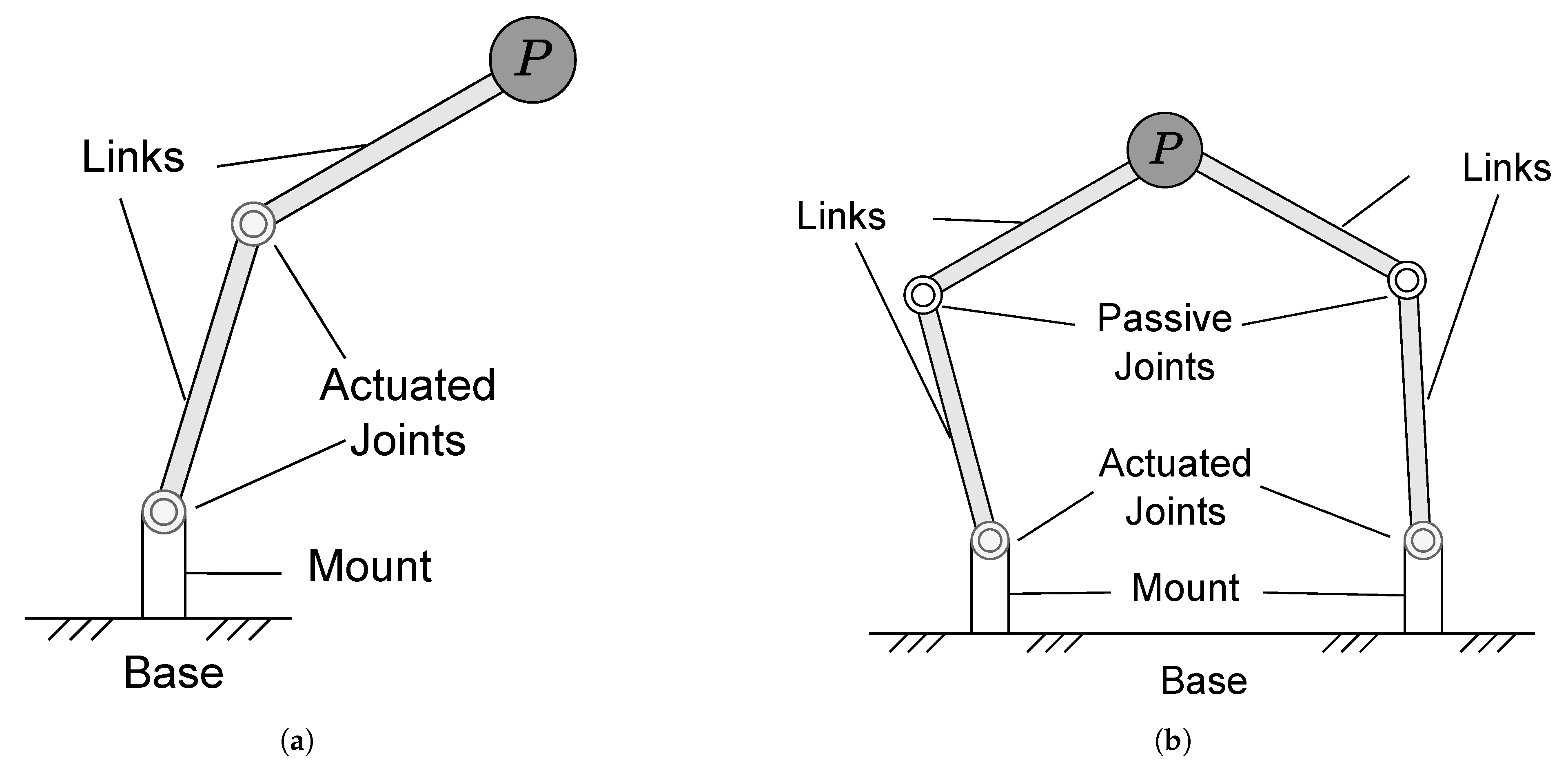
Figure 1. Two-DOF planar robotic manipulator examples: (a) serial, (b) parallel. These consist of links, connected by joints that allow motion, attached to a base (ground-fixed or mobile). P is the payload at the end-effector that is manipulated in order to fulfill the manipulation task. The robot moves the actuated joints and manipulates the payload through the mechanism geometry and joint kinematics.
Robotics 14 00151 g001
Figure 2. Reaction forces and moments exerted by a 2-DOF serial manipulator. The world frame axes are shown on the left. Gravity acts in the negative z direction, and acts at the center of mass of the links as f g 1 and f g 2 . Reaction forces applied on the base are f x and f z , and the reaction moment is τ y . The manipulator has gravity forces (in green), actuated joint torques τ 1 and τ 2 , and inertial forces/moments (in yellow).
Robotics 14 00151 g002
Figure 3. The kinematics of a simple 2-DOF open chain, fully actuated manipulator. The world frame axes is shown as colored on left, and the pose of frames O 1 and O 2 are also shown with the same colors. The center of mass of the manipulator is the checkered circle and its position vector is r C .
Robotics 14 00151 g003
Figure 4. A 1-DOF manipulator with spring attached to the base. The spring is compressed along the z-axis (with horizontal component negligible) at equilibrium and its force counteracts the gravity of the link.
Robotics 14 00151 g004
Figure 5. A 1-DOF manipulator where the link and payload (P) are balanced with a counter-mass. The link is extended behind and the counter mass (C) is attached, so that the center of mass (checkered circle) is positioned directly at the joint origin (colored axes).
Robotics 14 00151 g005
Figure 6. A 1-DOF manipulator balanced with a CM (to balance the CoM about the joint) and separate CR (to counter the joint actuation torques). The CoM of the link and CM is at the joint origin (checkered circle).
Robotics 14 00151 g006
Figure 7. A 1-DOF manipulator balanced with a CRCM. It is attached to the link and the inertial element, negatively coupled to θ with a constant transmission ratio. Combined with the counter mass, it has inertia I * about the joint origin (also center of mass), indicated as the checkered circle. The CRCM rotates with velocity θ ˙ * relative to the manipulator velocity θ ˙ .
Robotics 14 00151 g007
Figure 8. A 1-DOF manipulator balanced using duplicate mechanisms. Four copies are needed for dynamic balancing, geared to the original joint O 1 . O 2 , O 3 , O 4 are the origins of the duplicate links. The center of mass (checkered circle) is in the center of all 4 mechanisms.
Robotics 14 00151 g008
Figure 9. A force-balanced 1-DOF four-bar linkage, where the centers of masses of the links are indicated with e i and f i . The center of mass S is static with respect to the fixed bar A D . The linear momentum is zero for all admissible configurations and joint velocities.
Robotics 14 00151 g009
Figure 10. A physical prototype of a principal vector 5-link balanced mechanism, developed by van der Wijk [21].
Robotics 14 00151 g010
Figure 11. Three-DOF manipulators synthesized from one-DOF dynamically balanced four-bar linkages [75]: (a) planar, (b) spatial.
Robotics 14 00151 g011
Figure 12. A lightweight 2-DOF manipulator with active CM-based balancing in the horizontal axis, by Al Akhras et al. [64].
Robotics 14 00151 g012
Figure 13. The ADAPT manipulator presented in [125], from 3 synthesized force-balanced pantograph legs.
Robotics 14 00151 g013
Figure 14. The PAMINSA manipulator [101].
Robotics 14 00151 g014
Figure 15. The prototype of a 1-DOF dynamically balanced manipulator developed in [118].
Robotics 14 00151 g015
Figure 16. The Super-B manipulator developed by Boere et al. [123]: (a) design, (b) prototype.
Robotics 14 00151 g016
Figure 17. DUAL-V manipulator built and tested by van der Wijk et al. [97].
Robotics 14 00151 g017
Table 1. A summary of all the methods for dynamic balancing as categorized in this paper.
CategoryApproachAdvantagesDisadvantagesRelevant Papers
Passive Component AdditionSprings- Lightweight
- Compact
- Low Mass Addition
- Only achieves static balance
- Expends energy during motion from equilibrium
- Constrains the motion to be within the linear elastic region of deflection
[17,35,36,37,40,41,43,51,79,89,102]
Counter Mass (CM)
Counter Inertia (CI)
- Simple modifications to an existing mechanism
- Kinematic equations do not increase in complexity
- Can be implemented compactly
- CM Only achieves force balance
- Increases overall mass and inertia
- Tradeoff between mass/inertia and space increase
- Can increase moments/joint torques at high accelerations
- CI requires precise modifications of link inertia
[12,49,52,54,56,59,60,63,64,69,103,104,105,106]
Counter Rotating
Counter Mass
(CRCM)
- Simultaneously low mass and low
space addition
- Complex kinematic design
- Mechanically complex to implement in practice
[49,55,56,58,105,107]
Additional Linkage mechanism (ALM)- Low mass addition
- Increases stiffness and rigidity
- Significant increase in space
- Can restrict workspace due to additional complexity in kinematics
[17,48,51,55,59,87,105,108]
Active Component AdditionActive CRCM/ADBU- Highly Compact
- Low Mass/Inertia addition
- Can be placed in a variety of locations
- Can balance all forces and torques simultaneously
- Requires actuation
- Mechanical limits to forces and torques that can be balanced
- Complex to design and implement
[61,67,68,69,109]
Inherent Dynamic BalancingParallel Mechanisms- Can synthesize to form higher DOF planar or spatial mechanisms.
- Lower mass increase than CM/CI applied to serial mechanisms
- Multiple kinematic designs for any set of balancing conditions
- Designs can restrict workspace due to interference or singularities
- Complex kinematics and mechanical design
[11,16,57,71,74,75,77,78,93,98,101,110,111,112,113,114,115,116,117,118]
Principal Vector Designs- Low mass increase
- Well-established mathematical methods of solving for balance
- Very large mass and inertia
- Complex mechanical design (particularly joint design)
[85,88,91]
Parallel-Piped- Design optimizes in 3D for balance
conditions
- Large mass increase
- Complex mechanical design (particularly joint design)
[81,82]
Synthesized mechanisms - Can combine the advantages of different methods (from the above)
- Build complex mechanisms from simpler balanced components which are easier to solve for balance
- Complex combinations of designs which can be difficult to implement practically
- Redundant components (masses, inertias) are added which could be reduced if the entire mechanism is optimized
[35,53,76,82,90,91,92,93,94,97,98,99,116]
Table 2. A summary of all papers with a built prototype, categorized according to type of balancing, dimension (planar or spatial), balanced DOF, and motion DOF. For each paper, the balancing method as well as experimental metrics for results are provided.
Type of BalanceDimensionBalanced DOFMotion DOFPaperMethodExperimental metrics
GravityPlanar12[119]SpringJoint torques
12[120]SpringJoint angles
13[87]ALM, Active CMJoint angles
13[42]SpringJoint torques
13[121]SpringJoint torques
Spatial13[38]Active ALMJoint torques, end-effector position
StaticPlanar12[66]Active CMReaction moments, base position
13[64]Active CMBase rotation
15[6]Active CMJoint torques, base orientation
33[35]CM/CR, CRCM, ALMJoint torques (simulation)
Spatial34[122]Spring, ALMJoint torques
36[108]Active ALMBase displacement
Static and MomentPlanar23[65]Active CM, Inherent BalancingBase orientation
ForcePlanar22[103]CMJoint Torques
Spatial33[53]Synthesized MechanismReaction forces
34[101]Synthesized MechanismActuator torques
36[52]CMReaction forces and moments
DynamicPlanar31[118]Inherent BalancingAngular acceleration, joint torque
32[123]Inherent BalancingReaction forces and moment
32[59]ALM, CM/CR, CRCMJoint torques
33[124]Synthesized MechanismEnd-effector position
34[97]Synthesized MechanismEnd-effector position, reaction forces/moments
Spatial34[109]ADBUEnd-effector position
Disclaimer/Publisher’s Note: The statements, opinions and data contained in all publications are solely those of the individual author(s) and contributor(s) and not of MDPI and/or the editor(s). MDPI and/or the editor(s) disclaim responsibility for any injury to people or property resulting from any ideas, methods, instructions or products referred to in the content.