Abstract
Robotic fish are ideal for surveying fish resources and performing underwater structural inspections. If a robot is sufficiently fishlike in appearance and does not use a screw propeller, real fish will not be easily surprised by it. However, it is comparatively difficult for such a robot to determine its own position in water. Radio signals, such as those used by GPS, cannot be easily received. Moreover, sound ranging is impractical because of the presence of rocks and waterweed in places where fish spend a lot of time. For practical applications such as photographing fish, a robotic fish needs to follow the target fish without losing awareness of its own position, in order to be able to swim autonomously. We have developed a robotic fish named FOCUS (FPGA Offline Control Underwater Searcher) which is equipped with two CMOS cameras and a field-programmable gate array (FPGA) circuit board for data processing. The forward-facing camera is used to track red objects, since this is the color of the fish of interest. In addition, using visual information obtained with the bottom-facing camera, the robot can estimate its present position. This is achieved by performing real-time digital image correlation using the FPGA. However, until now, the position estimation accuracy has been poor due to the influence of yaw and roll. In the present study, the position estimation method has been greatly improved by taking into account the yaw and roll values measured using gyro sensors.
1. Introduction
The influence of global warming and acid rain is gradually changing the water quality in rivers and lakes. One method of checking water quality is by determining the amount of dissolved oxygen. Another approach is to investigate the number of creatures living in the water, and the species that are present. Creatures that can only thrive in good-quality water will not be found when the water quality is bad. Therefore, the water quality can be evaluated by classifying the species of living creatures such as fish.
Rather than have researchers enter the water to survey fish species, one interesting approach is to use a robotic fish that is capable of photographing real fish. Such a robot should be as small as possible in order to avoid frightening the target fish. It must also be able to swim autonomously and to track and photograph the target fish for the required period of time. After this, it can be retrieved and its data transferred to a computer. To achieve this level of autonomy, the robot must be constantly aware of its own position.
A number of underwater robots such as robotic fish have already been developed [1,2,3,4,5,6], including by our group [7,8,9]. In an event held in the Suma Aqualife Park in Japan, it was found that aquarium fish were not frightened by robotic fish when they were placed in the same water tank [10]. Another advantage of robotic fish is that they can swim even in constricted areas where conventional underwater robots used for oceanographic surveys cannot enter [11,12,13,14,15,16]. In addition, since their propulsion system is a fin just like in real fish, it does not become entangled in waterweed. However, the performance of a fin is still inferior to that of a screw propeller, and we are currently investigating ways of improving this. We are also comparing the propulsion mechanisms of real fish and robotic fish [17,18,19,20,21].
As stated earlier, the goal is to develop a robotic fish that is capable of identifying and photographing real fish. There are several methods by which such identification could be performed, such as using color information, shape information, and motion information. Of these, by far the simplest method is to identify fish based on their color, and this is the approach that we have been pursuing [22]. As we plan to evaluate the effectiveness of this method in the near future by tracking young carp, whose bodies are red, the present study focuses on identifying red objects.
The robotic fish used in this study is referred to as FOCUS (FPGA Offline Control Underwater Searcher), and is equipped with two small CMOS cameras and a field-programmable gate array (FPGA). It can track a red target autonomously using a forward-facing camera. A second CMOS camera points downwards and is used by FOCUS to identify its own position. Position estimation can be difficult underwater because radio signals such as those used by GPS cannot be easily received. Moreover, sound ranging is impractical because of the presence of rocks and waterweed in places where fish spend a lot of time, and the difficulty of accurately positioning sound sources. For these reasons, we have taken the approach of position estimation using visual images of the floor at the bottom of the water [23,24]. This is achieved using digital image correlation (DIC), which has proved useful in a variety of fields [25,26]. If the water is clear and shallow, this method is considered to be potentially simpler and more effective than approaches such as sound localization and particle filters [27,28,29]. In the present study, in order to improve the accuracy of position estimation using DIC, the effects of yaw and roll are taken into account using data from gyro sensors installed in the robotic fish.
2. Robotic Fish FOCUS
2.1. Structure of FOCUS
There has been a great deal of research on the propulsion method used by underwater creatures such as fish, which involves their caudal (tail) fin [30,31,32,33]. Fish generate a reverse Karman vortex street which allows them to swim fast and efficiently, and they move their entire body flexibly. Based on results previously obtained using test models, we believe that the flexibility of the caudal fin is an important factor for improving the propulsive performance of robotic fish. For this reason, FOCUS is equipped with a caudal fin made of a flexible material.
Figure 1 shows a photograph of FOCUS, and a schematic of its internal structure is shown in Figure 2. The robot has both forward- and downward-facing CMOS cameras. A 3D gyroscope with two bi-axial gyro sensors is installed to measure the pitch, roll and yaw motions of the robot. Image processing and motion control are carried out using an FPGA board containing a Spartan-6 XC6SLX9 (Xilinx Inc., San Jose, CA, USA).
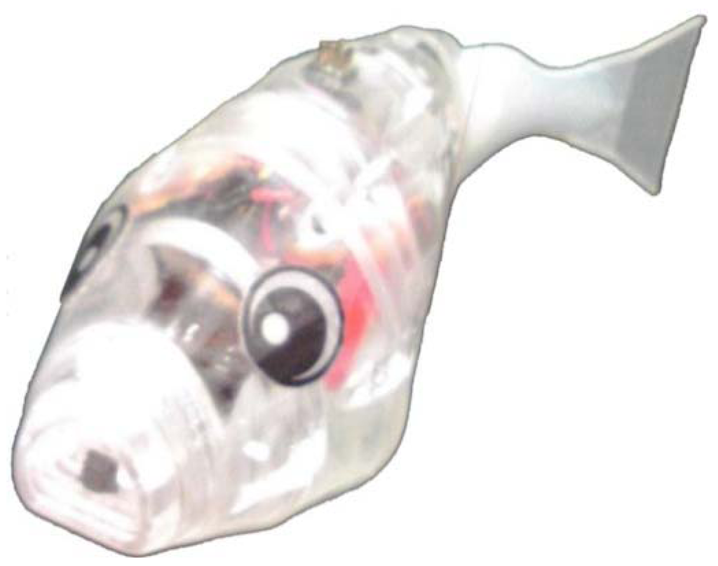
Figure 1.
Robotic fish FPGA Offline Control Underwater Searcher (FOCUS).
Figure 1.
Robotic fish FPGA Offline Control Underwater Searcher (FOCUS).


Figure 2.
Structure of FOCUS.
Figure 2.
Structure of FOCUS.
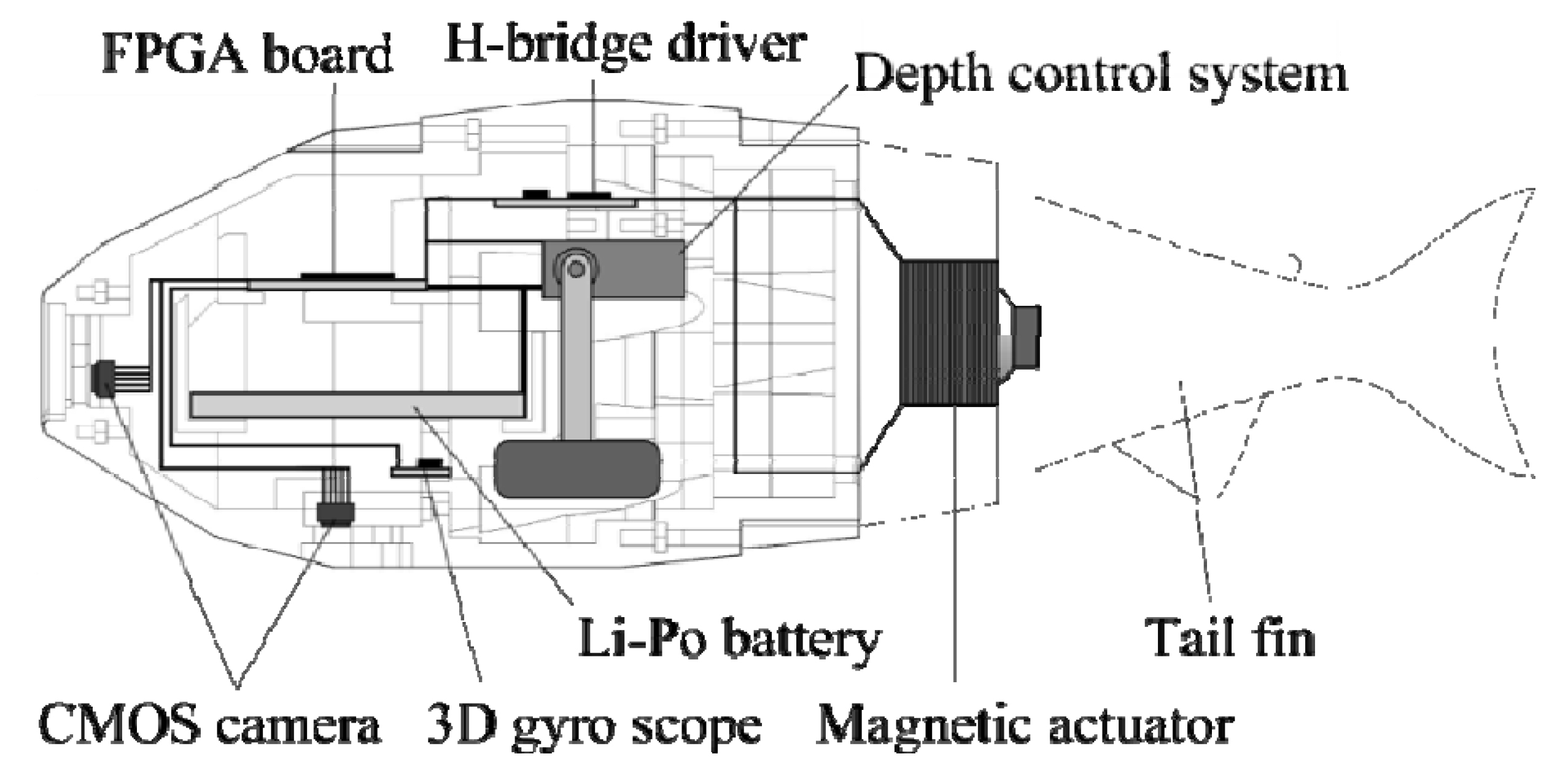
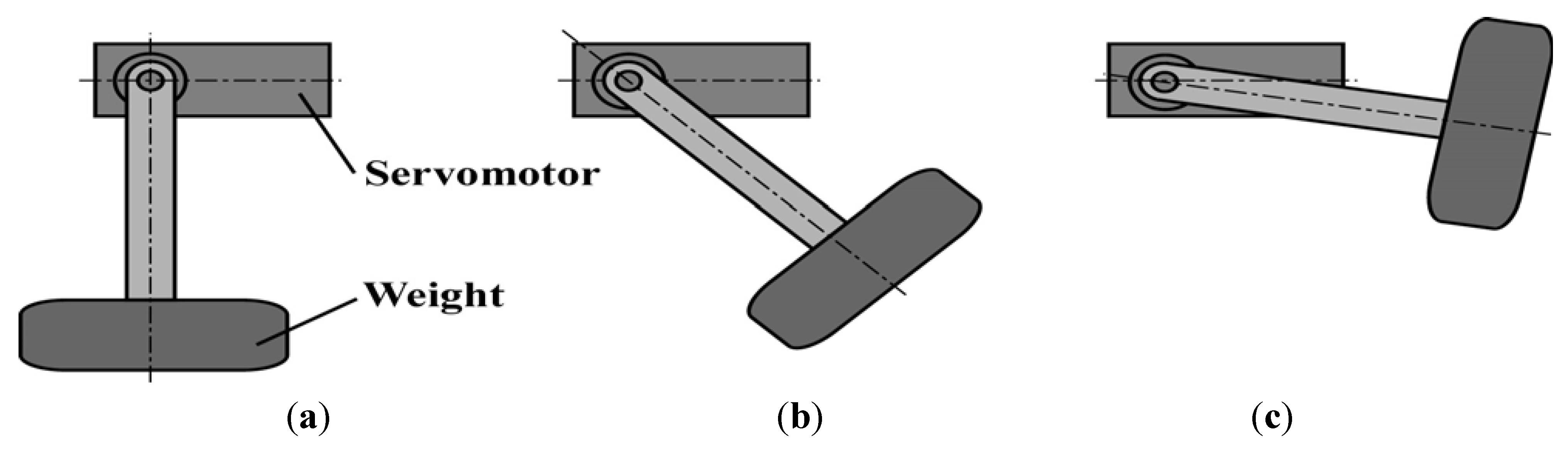
The outer shell is constructed from acrylic parts. The caudal fin is connected to the main body by a single joint, in which a magnetic actuator is installed, as illustrated in Figure 3. The coil in the actuator has 2000 turns of polyurethane wire with a diameter of 0.12 mm, and has a resistance of 175 Ω. A spherical neodymium magnet is installed inside the coil, and when a current passes through the coil, the tail fin attached to the magnet is driven by an electromagnetic force. A lithium polymer battery (3.7 V, 1,000 mAh) is used as the electric power source. Power is supplied to the magnetic actuator for the fin drive through an H-bridge circuit containing a power MOSFET (SP8M4). The servomotor (Tahmazo TS-1002) in the depth control system is driven by the electric power from the same battery, and receives commands from the FPGA board. Figure 4 shows a schematic diagram of the depth control system. When the weight is moved forward, the robot sinks, and when it is moved backwards, the robot rises.
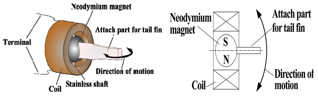
Figure 3.
Magnetic actuator used for FOCUS.
Figure 3.
Magnetic actuator used for FOCUS.
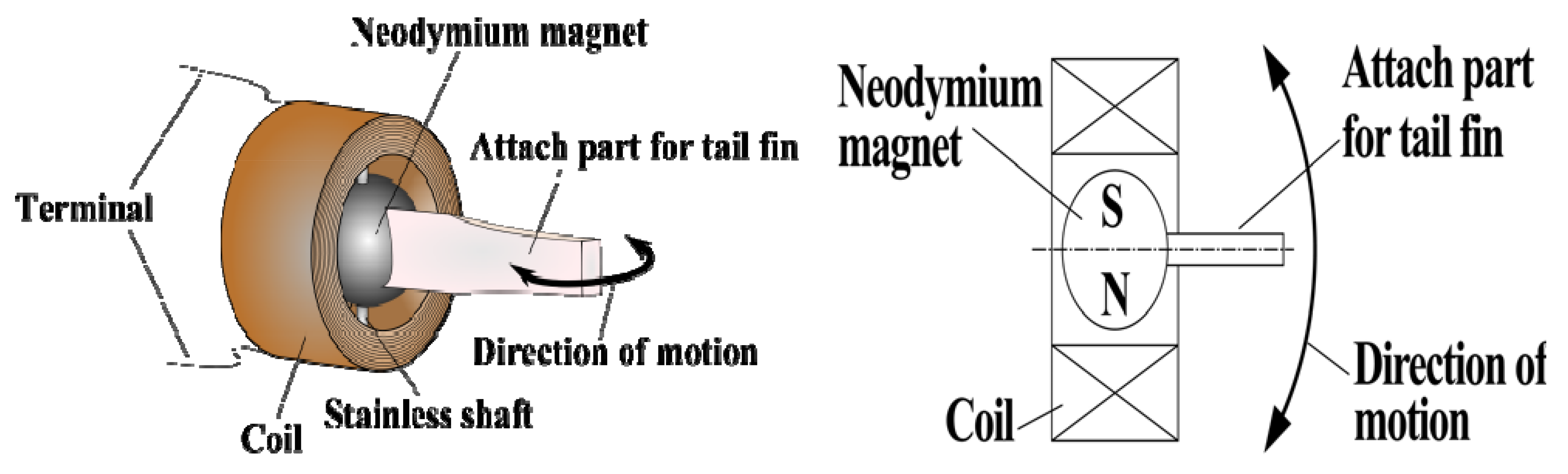

Figure 4.
Depth control system. (a) sinking; (b) level; (c) rising.
Figure 4.
Depth control system. (a) sinking; (b) level; (c) rising.
The magnetic actuator is controlled by signals from the FPGA. By outputting an alternating positive and negative voltage, the attached fin can be made to swing from side to side. The pulse-width-modulation duty ratio set by the VHDL program in the FPGA determines whether the robot swims straight ahead or turns right or left.
2.2. Target Tracking Method
The forward-facing camera on the head of the robot for target tracking has a resolution of 128 pixel × 96 pixel (Sub-QCIF), and the image data in RGB565 format are sent to the FPGA memory at 30 frames per second. The robotic fish can autonomously determine the correct traveling direction to track a red target based on the visual information obtained from the camera. It attempts to bring the center of the red area into the center of its own field of view, as shown in Figure 5.
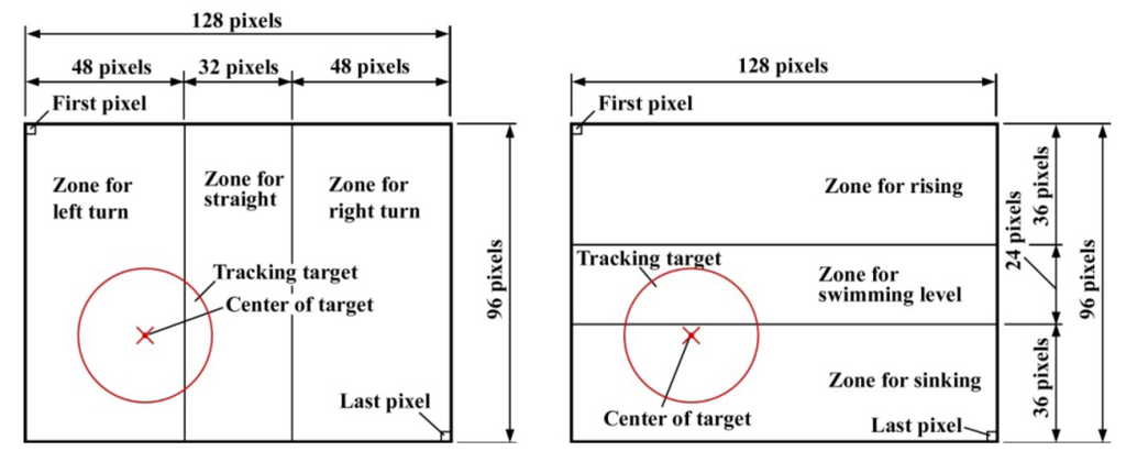
Figure 5.
Visual method for guiding FOCUS.
Figure 5.
Visual method for guiding FOCUS.

The procedure is as follows. For an image containing a red target, a summation (ΣX) is made of the X coordinates of pixels identified as red, for all pixels from the upper left to the lower right in Figure 5. The centroid Xg in the X direction for the red region is then determined by dividing ΣX by the total number of red pixels N. If Xg is larger than 80 pixels, the robot turns right, and if it is smaller than 48 pixels, it turns left. Otherwise, it swims straight. A similar analysis is carried out in the Y direction to determine whether the robot should rise, sink or swim level.
The ability of FOCUS to track a red target was experimentally investigated. The results are shown in Figure 6, and it was confirmed that tracking could be carried out successfully. The average swimming velocity of the robotic fish was 123 mm/s, which was obtained by measurements of 50 times target tracking swim experiment. The angular velocity of the robotic fish is 0.52 rad/s. When the target movement exceeds the kinematic performance of the robot, it becomes impossible to track the target.
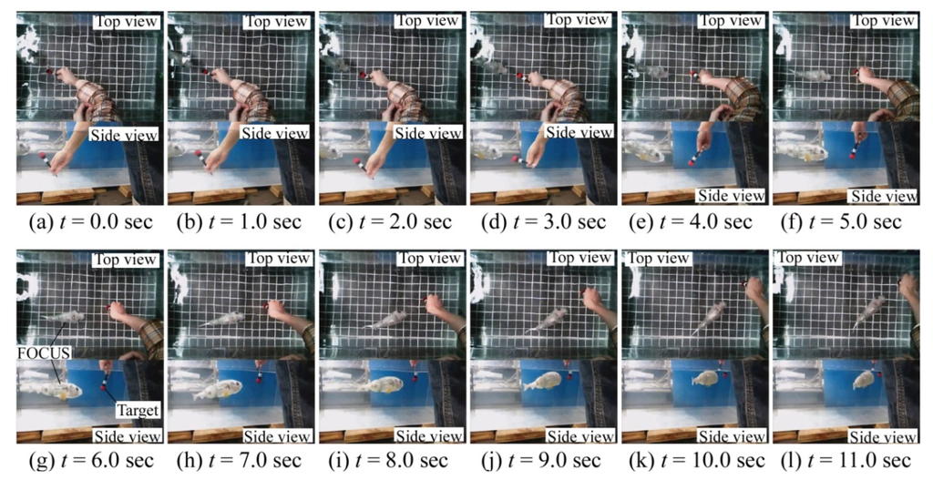
Figure 6.
FOCUS following a red target object.
Figure 6.
FOCUS following a red target object.

3. Position Estimation
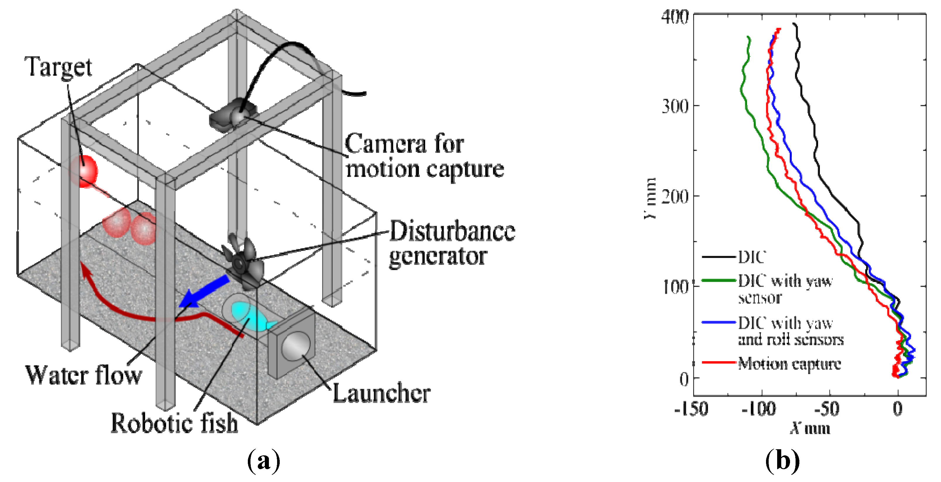
To evaluate the position estimation capability of FOCUS, a launcher containing the robot was placed in a tank with a length of 900 mm, a width of 450 mm, and height of 450 mm, which contained tap water, as illustrated in Figure 7a. The robotic fish swam horizontally without a target, at a distance of 100 mm from the bottom of the tank, which was lined with eight A4 size photographs of small pebbles in a river. The composite image is shown in Figure 7b; its dimensions were 796 mm × 576 mm.
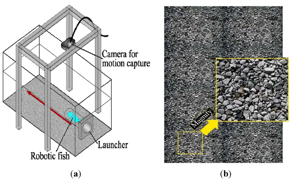
Figure 7.
Position estimation experiment: (a) water tank and (b) image of small pebbles.
Figure 7.
Position estimation experiment: (a) water tank and (b) image of small pebbles.
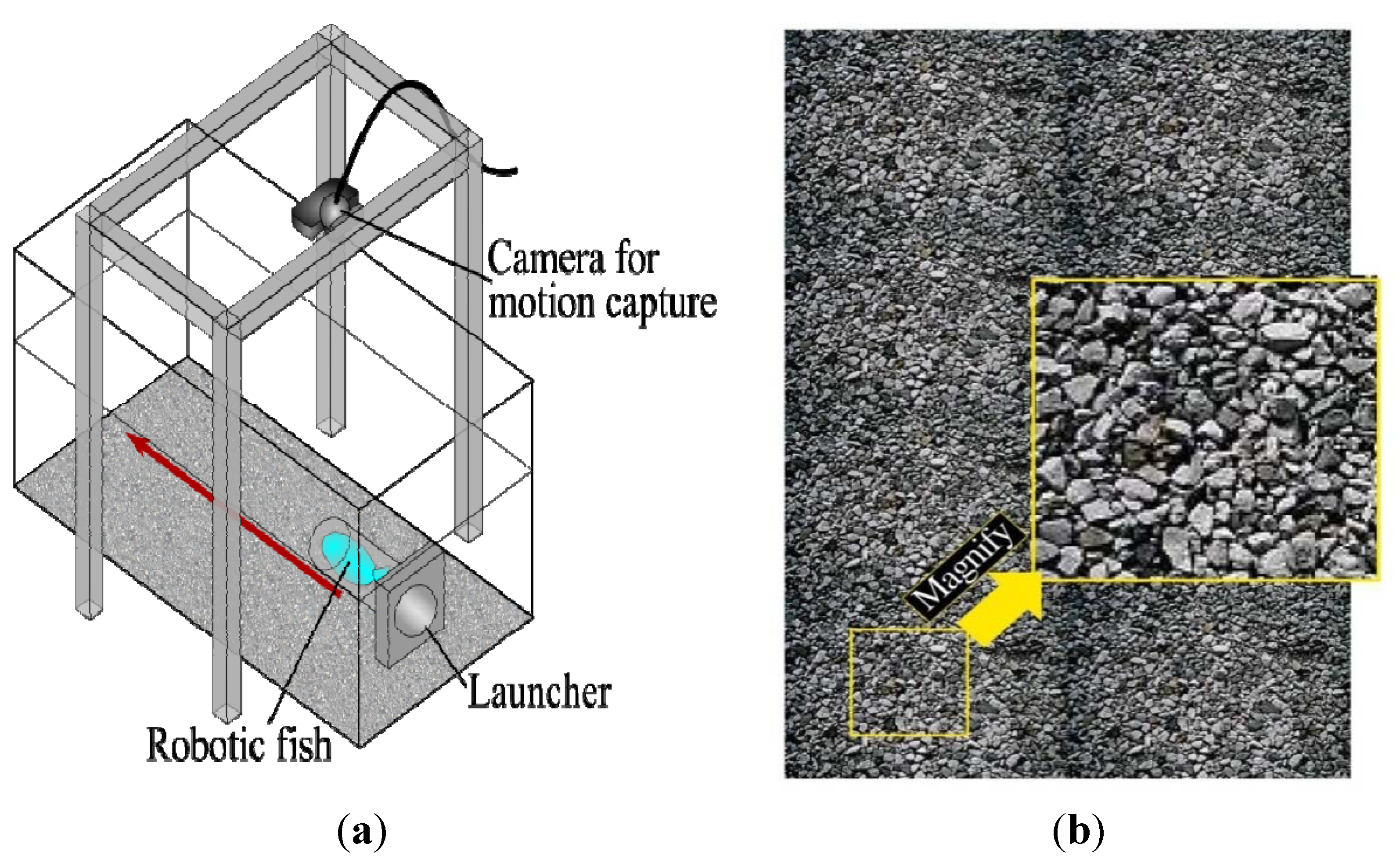
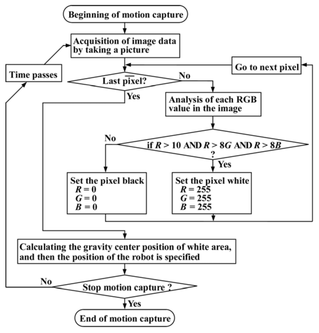
Figure 8.
Flow chart of motion capture process.
Figure 8.
Flow chart of motion capture process.

The accuracy of the position estimation technique was evaluated using a motion capture camera mounted above the water tank, which acquires 8-bit RGB images. Figure 8 shows a flow chart of the motion capture process. Its purpose was to track the center position of the red robotic fish. The color of each pixel was evaluated, and if R > 10, R > 8G, and R > 8B then the pixel was judged to be red. Since the camera acquired images at 30 frames per second, the location of the robot could be determined at intervals of approximately 33.3 ms.
The method used by the robotic fish to estimate its position is as follows. The downward-facing camera captures images of the pebble pattern at a resolution of 64 pixel × 64 pixel. For the first image, the 32 pixel × 32 pixel central region is extracted and stored in the FPGA memory. After about 33 ms, a second 64 pixel × 64 pixel image is captured and stored in the FPGA. This 64 pixel × 64 pixel image can be thought of as containing a total of 1,089 (33 × 33) unique sub-images with dimensions of 32 pixel × 32 pixel, one of which correlates most closely with the first 32 pixel × 32 pixel image. Identifying this sub-image yields the distance (∆X, ∆Y) that the robotic fish swam during the 33-ms interval. To evaluate the correlation between images, the residual sum of squares was used:
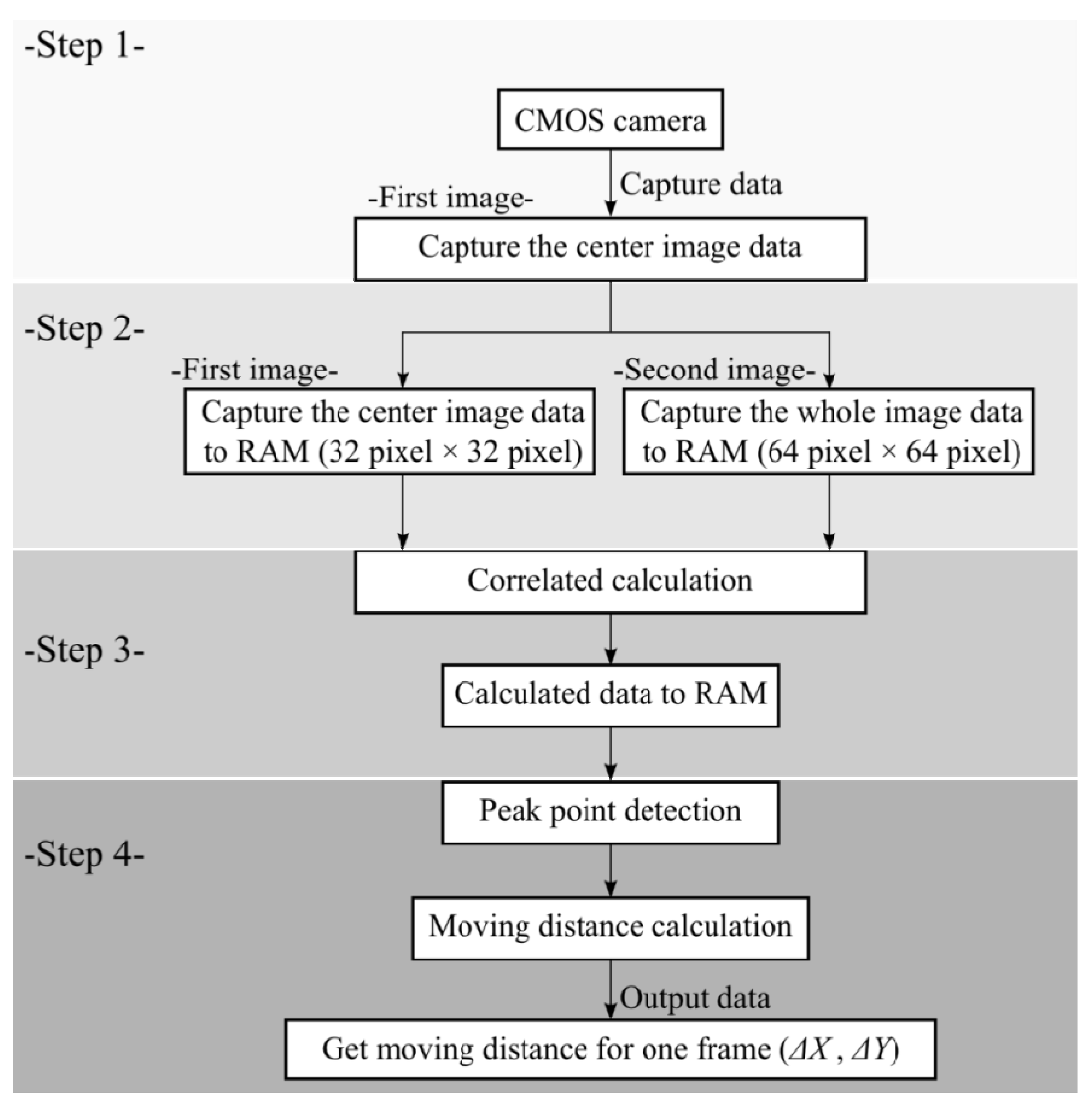
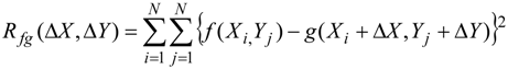 where Rfg is the correlation value, f is the luminance at pixel (Xi, Yj) in the first 32 pixel × 32 pixel image, g is the luminance at pixel (Xi, Yj) in the candidate region in the second image, and N is the number of pixels (32) in the X and Y directions. Figure 9 shows the flow chart to get the distance of ∆X, ∆Y.

Figure 9.
Flow chart of digital image correlation method.
Figure 9.
Flow chart of digital image correlation method.
As the robotic fish swims, it is subject to yaw and roll motions. This can bring about a situation in which the most highly correlated region of the second image is far from the image center, or in extreme cases, is not contained within the 64 pixel × 64 pixel image at all. This can lead to a large increase in the number of correlation calculations that must be performed. This is particularly true for roll motion. However, increasing the number of candidate images considered is difficult due to the limited memory and number of multipliers in the FPGA. Therefore, to compensate for the effects of yaw and roll, the X and Y coordinates in the second image were transformed using the yaw and roll angles θyaw and θroll, respectively, obtained by integrating the angular velocities measured by the gyro sensors. We used LPR503AL and LPY503AL as gyro sensors. The moving average method was used to remove the sensor’s drift. Figure 10 shows the method used for yaw compensation, and Figure 11 shows the case for both yaw and roll compensation.
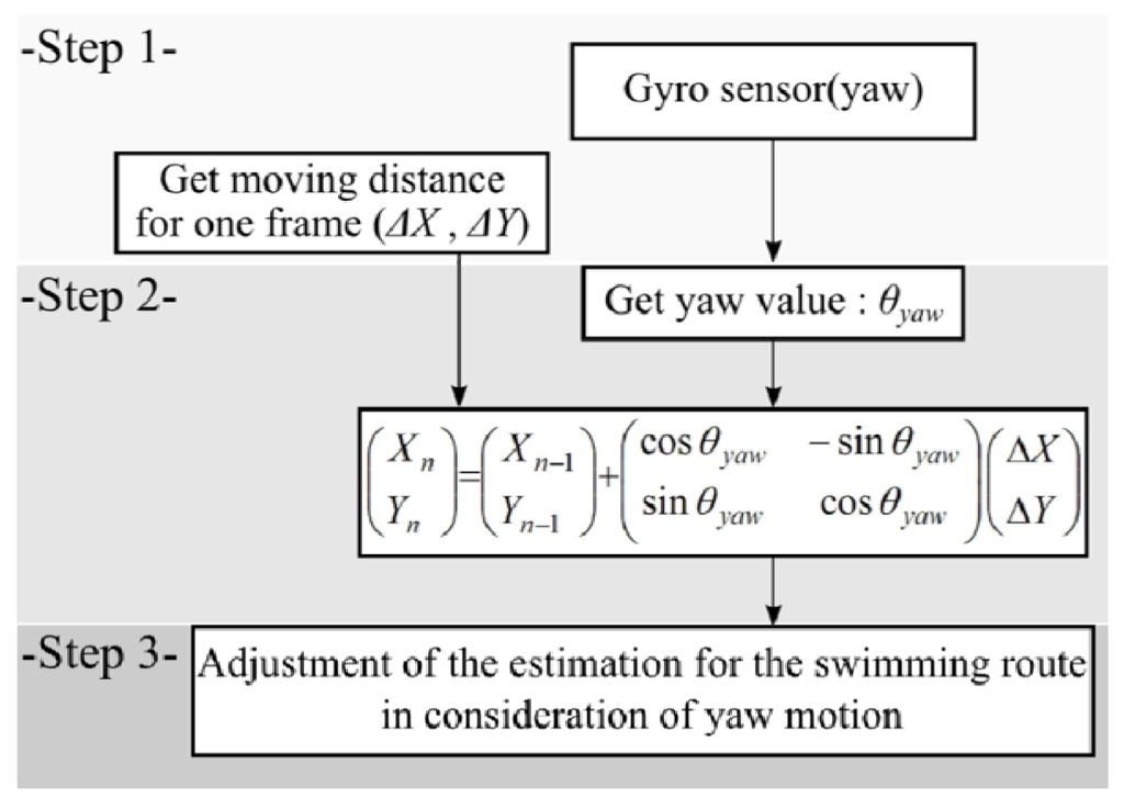
Figure 10.
Flow chart of yaw compensation method.
Figure 10.
Flow chart of yaw compensation method.


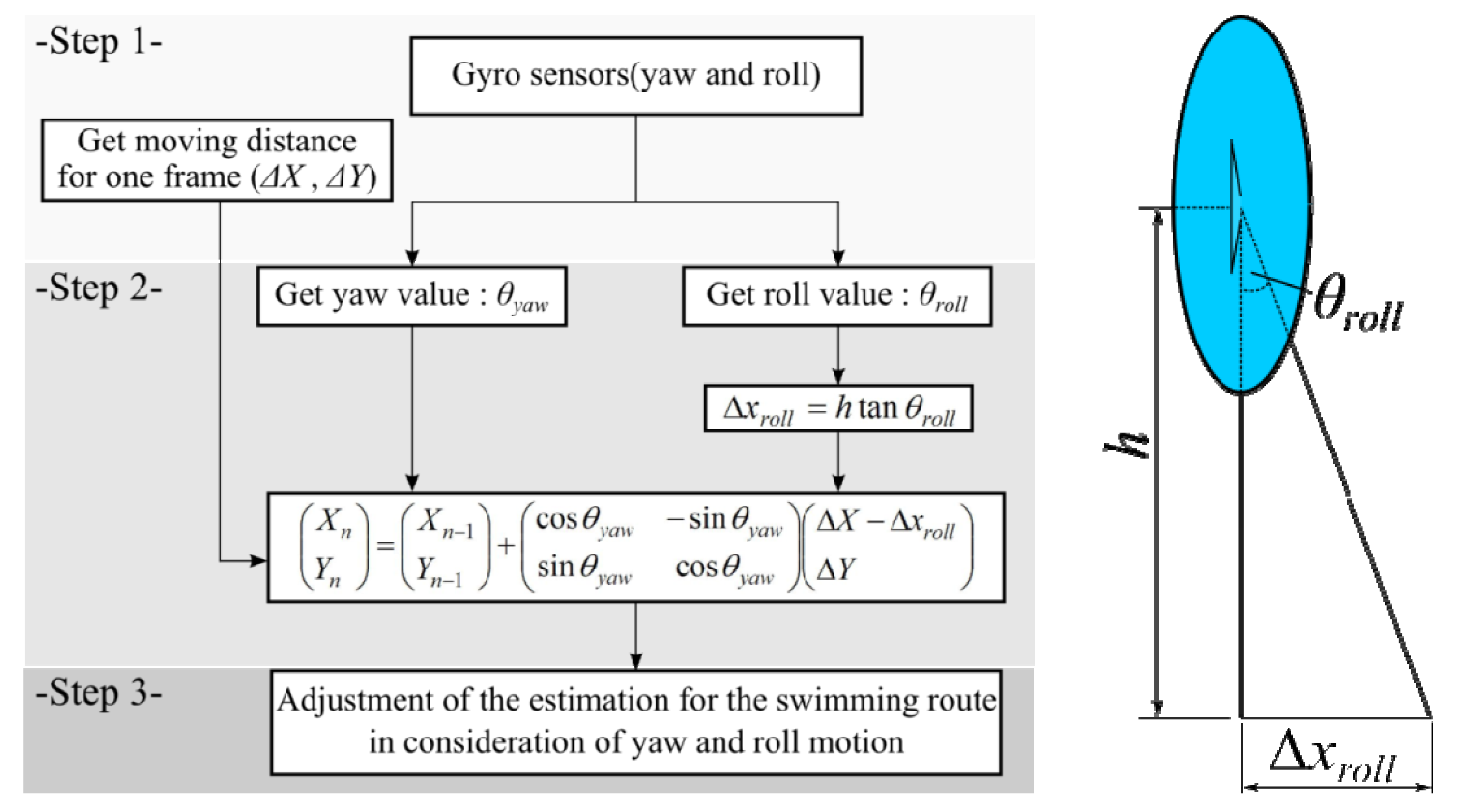
Figure 11.
Flow chart of yaw and roll compensation method.
Figure 11.
Flow chart of yaw and roll compensation method.
Although the yaw and roll angle calculations can be performed in the FPGA, and the position can be estimated, the robot cannot output the full set of results, including the raw DIC results, those following yaw compensation, and those following yaw and roll compensation. Since all of this information is needed in order to evaluate the relative effectiveness of the different position estimation methods, the robot outputs the X, Y, θyaw and θroll values to a notebook computer, which can also perform the position estimations. Thus, all of the data required to evaluate the effectiveness of the different methods can be obtained in a single swimming experiment.
Figure 12 shows the results of the accuracy evaluation experiment. In the absence of a tracking target, the robot tends to drift left or right due a slight imbalance in the horizontal forces produced by the magnetic actuator. In this experiment, it exhibited a small deviation to the left. The red curve represents the actual trajectory captured by the motion capture camera. The black curve indicates the trajectory determined using DIC only, and it is seen to deviate from the actual position. In contrast, the trajectory estimated using yaw and roll compensation (blue curve) is close to the true trajectory.
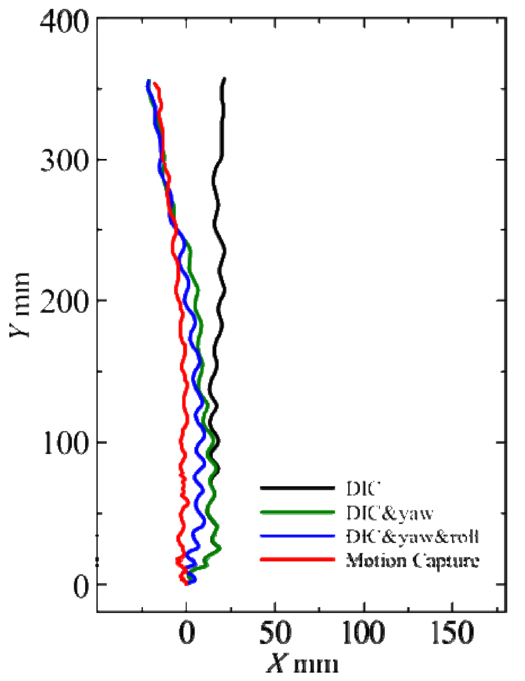
Figure 12.
Accuracy of position estimation using various methods during free swimming.
Figure 12.
Accuracy of position estimation using various methods during free swimming.

In the next experiment, the robotic fish was guided in a rightward arc using a red target object as shown in Figure 13a. The experimental results are shown in Figure 13b. Again, the blue trajectory obtained using yaw and roll compensation is closest to the actual trajectory shown in red. It should be noted that yaw compensation could also be performed by using a DIC method that takes image rotation into account. However, the results of several experiments indicated that the method based on gyro sensor measurements was superior.
For a robotic fish to be used under real environmental conditions, it is necessary to consider the effects of flowing water, particularly in rivers. To simulate these kinds of conditions, a screw propeller was placed in the water tank to produce a flow across the trajectory of the robot, as shown in Figure 14a. The robotic fish was again guided towards the opposite wall using a red target. When the robot enters this cross flow, it is knocked off balance because the hydraulic force acts on a point some distance from its center of gravity. However, as seen in Figure 14b, the trajectory obtained using yaw and roll compensation is quite close to the true trajectory.

Figure 13.
Guided swimming experiment: (a) experimental setup and (b) experimental results.
Figure 13.
Guided swimming experiment: (a) experimental setup and (b) experimental results.
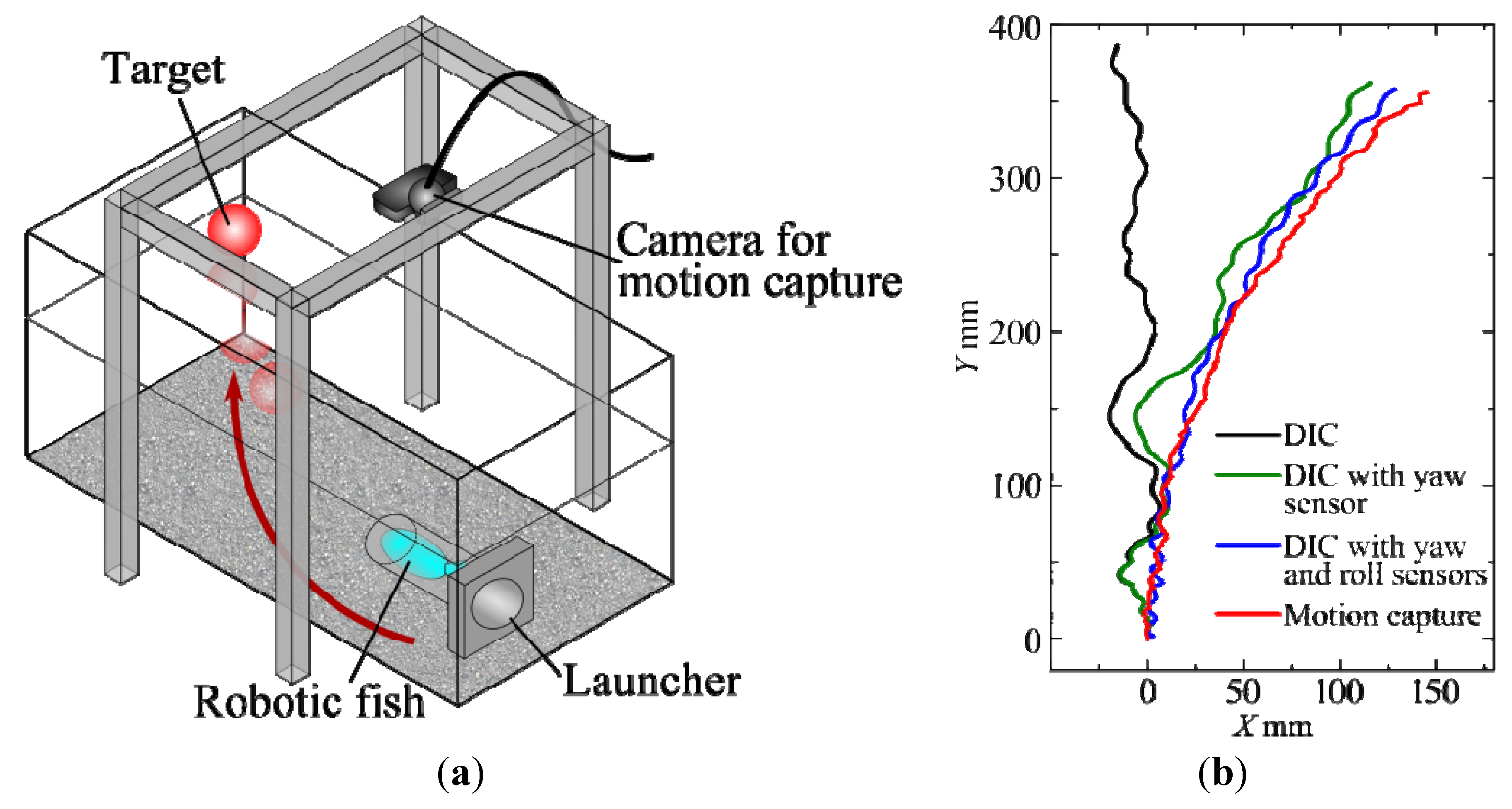

Figure 14.
Swimming experiment with disturbed water flow: (a) experimental setup and (b) experimental results.
Figure 14.
Swimming experiment with disturbed water flow: (a) experimental setup and (b) experimental results.
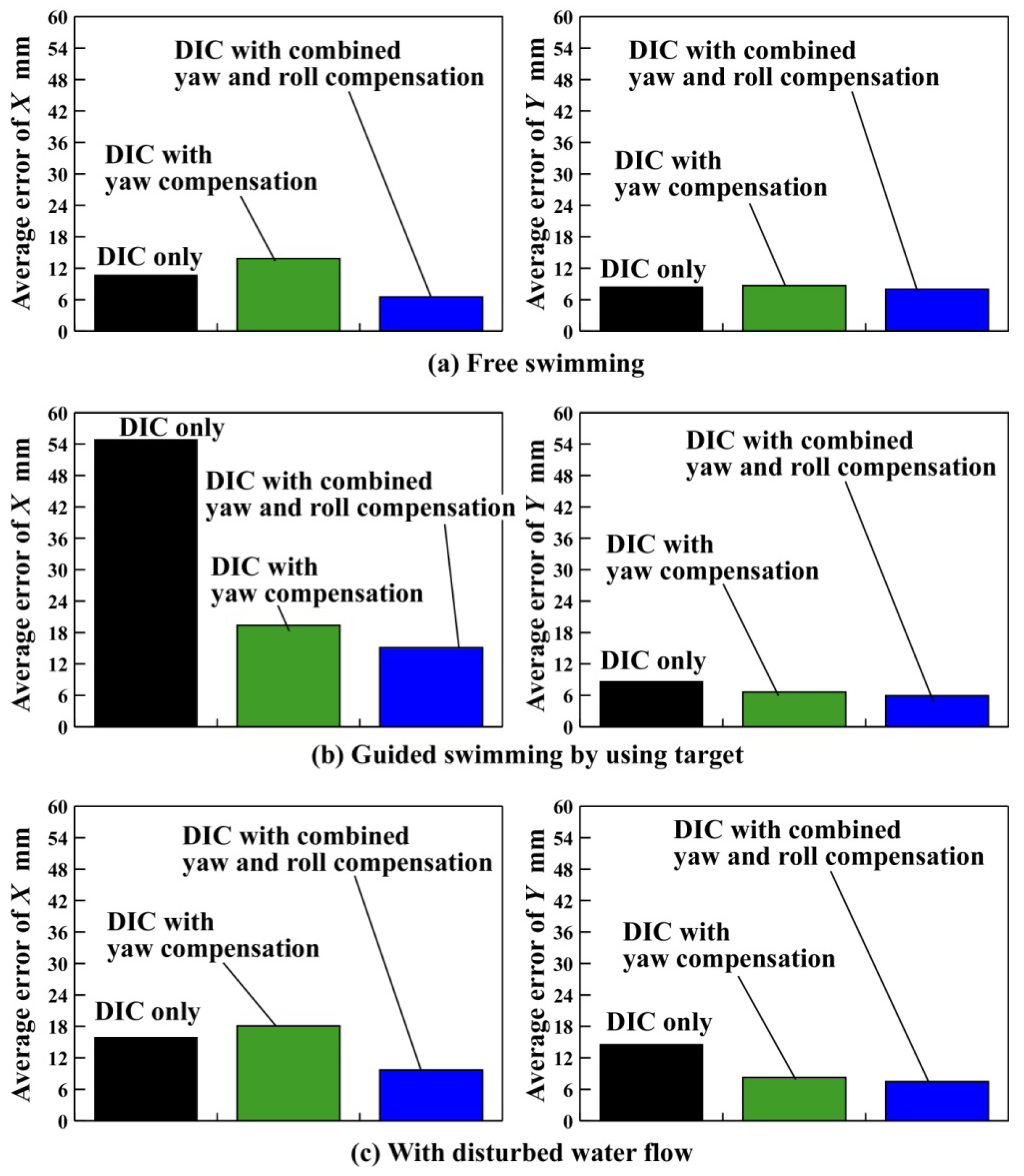
The position estimation with yaw and roll still had some errors in Figure 12 , Figure 13 and Figure 14. There are initial position errors and initial angle errors in every experiment because the person put the robotic fish in the launcher. Moreover, human errors might cause easily because a person pushes the button to start the measurement. Therefore, the experiments of Figure 12 , Figure 13 and Figure 14 were conducted 8 times respectively because there might be the man-made errors in each experiment. Figure 15 shows a comparison of the accuracy of the different position evaluation methods. Each bar represents the average error between the estimated positions during the experiments and the true positions. It can be seen that in each case, the smallest error is obtained when combined yaw and roll compensation is used.

Figure 15.
Accuracy of different position evaluation techniques.
Figure 15.
Accuracy of different position evaluation techniques.
There are a lot of factors for the position errors; such as DIC, drift of gyro sensor, pitch motion and man-made errors. It is extremely important to reduce the error from the large error factor. Therefore, the magnitude relation among the errors should be clarified.
4. Conclusions
A small robotic fish (FOCUS) equipped with two CMOS cameras and an FPGA was fabricated in order to test its ability to swim autonomously in clear shallow water. The forward-facing camera was used to track and follow target objects. The downward-facing camera was used by the robot to estimate its position based on a DIC technique, and gyro sensors were installed to provide yaw and roll information. It was found that using DIC alone, with no consideration for image rotation due to yaw, the robot could not estimate its position accurately. However, the accuracy was greatly improved when both the yaw and roll values obtained by the gyro sensors were taken into account. Good experimental results were obtained for free swimming, guided swimming, and swimming through a cross flow.
The experiments in this study were performed at a constant distance from the bottom of the water tank. In future work, the effectiveness of the position estimation method will be evaluated in situations where the robotic fish is changing its vertical position.
Acknowledgments
The authors would like to express their gratitude to the Japan Society for the Promotion of Science for support in the form of Grant-in-Aid for Scientific Research (C), No. 24560301.
Author Contributions
Keisuke Koyama manufactured the robotic fish FOCUS. Keisuke Koyama and Takahiro Usami performed swimming experiments of FOCUS for the position estimation. Yogo Takada came up with the idea for the position estimation of robotic fish and the structure of FOCUS, and wrote the paper.
Conflicts of Interest
The authors declare no conflict of interest.
References
- Hirata, K.; Takimoto, T.; Tamura, K. Study on turning performance of a fish robot. In Proceedings of the 1st International Symposium on Aqua Bio-Mechanisms, Honolulu, HI, USA, 28–30 August 2000; pp. 287–292.
- Nakashima, M.; Kaminaga, K.; Ono, K. Experimental study of two-joint dolphin robot (propulsive characteristics of 2nd large model). In Proceedings of the International Symposium on Aqua Bio-Mechanisms, Honolulu, HI, USA, 28–30 August 2000; pp. 311–314.
- Toda, Y.; Ikeda, H.; Sogihara, N. The motion of fish-like under-water vehicle two undulating side fins. In Proceedings of the 3rd International Symposium on Aqua Bio-Mechanisms, Okinawa, Japan, 3–7 July 2006.
- Kobayashi, S.; Nakabayashi, M.; Morikawa, H. Bioinspired propulsion mechanism in fluid using fin with dynamic variable-effective-length spring. J. Biomech. Sci. Eng. 2006, 1, 280–289. [Google Scholar] [CrossRef]
- Yamamoto, I. Research and development of robotic fish. J. JIME 2008, 43, 99–102. [Google Scholar] [CrossRef]
- Low, K.H. Modelling and parametric study of modular undulating fin rays for fish robots. Mech. Mach. Theory 2009, 44, 615–632. [Google Scholar] [CrossRef]
- Takada, Y.; Araki, R.; Nonogaki, M.; Ebita, K.; Ishii, T.; Wakisaka, T. Development of small and ultra-light passive-type polymer electrolyte fuel cell and application to small fish robots. Trans. Jpn. Soc. Mech. Eng. Ser. B 2010, 76, 650–659. [Google Scholar]
- Takada, Y.; Araki, R.; Nakanishi, Y.; Nonogaki, M.; Ebita, K.; Wakisaka, T. Development of small fish robots powered by small and ultra-light passive-type polymer electrolyte fuel cells. J. Robot. Mechatron. 2010, 22, 150–157. [Google Scholar]
- Takada, Y.; Masuda, H.; Tajiri, T.; Wakisaka, T. Development of small fish robot with built-in fuel cells. In Proceedings of the Techno-Ocean, Kobe, Japan, 27 July 2010.
- Techno-Ocean 2010 Pre Event, Ocean Science Seminar, Amazing World of Aqua Bio Mechanics. Available online: http://www.marine.osakafu-u.ac.jp/~lab06/pre-event/ (accessed on 28 January 2014).
- Asakawa, K.; Kojima, J.; Ito, Y.; Takagi, S.; Shirasaki, Y.; Kato, N. Autonomous underwater vehicle AQUA EXPLORER 1000 for inspection of underwater cables. In Proceedings of the AUV’96, Monterey, CA, USA, 2–6 June 1996.
- Ura, T. Construction of AUV R2D4 based on the success of full-autonomous exploration of Teisi Knoll by R-one robot. In Proceedings of the AUV Show Case, New Maiden, UK, 27–28 September 2002; pp. 23–28.
- Maeda, T.; Ishiguro, S.; Yokoyama, K.; Hirokawa, K.; Hashimoto, A.; Okuda, Y.; Tani, T. development of fuel cell AUV “URASHIMA”. Mitsubishi Heavy Ind. Tech. Rev. 2004, 41, 344–347. [Google Scholar]
- Nakatani, T.; Ura, T.; Ito, Y.; Kojima, J.; Tamura, K.; Sakamaki, T.; Nose, Y. AUV “TUNA-SAND” and its Exploration of hydrothermal vents at Kagoshima Bay. In Porceedings of the OCEANS 2008—MTS/IEEE Kobe Techno-Ocean, Kobe, Japan, 8–11 April 2008.
- Hyakudome, T.; Furuyama, H.; Baba, T.; Kasaya, T.; Oomika, S.; Ishibashi, S.; Yoshida, H.; Tsukioka, S.; Matsuura, M.; Aoki, T. The Seafloors Which AUV “URASHIMA” Watched. Available online: http://jairo.nii.ac.jp/0153/00013762/en (accessed on 15 March 2014).
- Sakagami, N.; Ibata, D.; Ikeda, T.; Shibata, M.; Ueda, T.; Ishimaru, K.; Onishi, H.; Murakami, S.; Kawamura, S. Development of a removable multi-DOF manipulator system for man-portable underwater robots. In Proceedings of the 21th International Offshore and Polar Engineering Conference, Maui, HI, USA, 19–24 June 2011; pp. 279–284.
- Takada, Y.; Nakanishi, Y.; Araki, R.; Wakisaka, T. Investigation of propulsive force and water flow around a small fish robot by PIV Measurement and three-dimensional numerical analysis. Trans. Jpn. Soc. Mech. Eng. Ser. C 2010, 76, 665–672. [Google Scholar]
- Takada, Y.; Nakanishi, Y.; Araki, R.; Nonogaki, M.; Wakisaka, T. Effect of material and thickness about tail fins on propulsive performance of a small fish robot. J. Aero Aqua Bio-Mech. 2010, 1, 51–56. [Google Scholar] [CrossRef]
- Takada, Y.; Araki, R.; Ochiai, T.; Tajiri, T.; Wakisaka, T. Effects of tail fin flexibility on propulsive performance in small fish robots (investigation by fluid-structure interaction analysis considering elastic deformation of tail fin). Trans. Jpn. Soc. Mech. Eng. Ser. C 2011, 77, 2351–2362. [Google Scholar] [CrossRef]
- Takada, Y.; Ochiai, T.; Fukuzaki, N.; Tajiri, T.; Wakisaka, T. Analysis of flow around robotic fish by three-dimensional fluid-structure interaction simulation and evaluation of propulsive performance. J. Aero Aqua Bio-Mech. 2013, 3, 57–64. [Google Scholar] [CrossRef]
- Takada, Y.; Fukuzaki, N.; Ochiai, T.; Tajiri, T.; Wakisaka, T. Evaluation of artificial caudal fin for fish robot with two joints by using three-dimensional fluid-structure simulation. Adv. Mech. Eng. 2013, 2013. ID:310432. [Google Scholar] [CrossRef]
- Takada, T.; Nakamura, T.; Koyama, K.; Tajiri, T. Target following control of small fish robot FOCUS based on color information. Trans. Jpn. Soc. Mech. Eng.Ser. C 2012, 78, 2924–2934. [Google Scholar] [CrossRef]
- Takada, Y.; Nakamura, T.; Koyama, K.; Wakisaka, T. Self-position estimation of small fish robot based on visual information from camera. J. Jpn. Inst. Mar. Eng. 2012, 47, 138–146. [Google Scholar]
- Takada, Y.; Nakamura, T.; Koyama, K.; Fukuzaki, N.; Tajiri, T.; Wakisaka, T. Target following and self-position estimation of small fish robot FOCUS. J. Jpn. Inst. Mar. Eng. 2012, 47, 108–113. [Google Scholar]
- Kawasue, K.; Ishimatsu, T.; Shih, C. Fast correlation technique of particle image velocimetry. Trans. Jpn. Soc. Mech. Eng. Ser. C 1994, 60, 2084–2089. [Google Scholar] [CrossRef]
- Uneda, M.; Murata, S.; Narise, T.; Yamazaki, T.; Ohnishi, O.; Kurokawa, S.; Ishikawa, K.; Doi, T. Quantitative evaluation of slurry flow behavior using digital image processing. Trans. Jpn. Soc. Mech. Eng. Ser. C 2011, 77, 3891–3903. [Google Scholar] [CrossRef]
- Maki, T.; Kondo, H.; Ura, T.; Sakamaki, T. AUVnavigation with particle filter. Month. J. Inst. Industrial Sci. 2004, 56, 429–433. [Google Scholar]
- Eriguchi, Y.; Ishii, K.; Watanabe, K. An underwater sound source localization system using probabilistic methods. Dyn. Des. Conf. 2009, 11, 244–247. [Google Scholar]
- Tajiri, T.; Takada, Y.; Takada, M.; Kawai, T. Movement control including localization for a wheeled mobile robot. In Proceedings of the 16th Asia Pacific Symposium on Intelligent and Evolutionary Systems, Kyoto, Japan, 13–14 December 2012; pp. 3–6.
- Gray, J. Studies in Animal Locomotion, VI. The Propulsive Power of the Dolphin. J. Exp. Biol. 1935, 13, 192–199. [Google Scholar]
- Lighthill, M.J. Note on the swimming of slender fish. J. Fluid Mech. 1960, 9, 305–317. [Google Scholar] [CrossRef]
- Lighthill, M.J. Aquatic animal propulsion of high hydrodynamical efficiency. J. Fluid Mech. 1970, 44, 265–301. [Google Scholar] [CrossRef]
- Nagai, M.; Teruya, I.; Uechi, K.; Miyazato, T. Study on an oscillating wing propulsion mechanism. Trans. JSME, Ser. B 1996, 62, 200–206. [Google Scholar] [CrossRef]
© 2014 by the authors; licensee MDPI, Basel, Switzerland. This article is an open access article distributed under the terms and conditions of the Creative Commons Attribution license (http://creativecommons.org/licenses/by/3.0/).