1. Introduction
Efficient and effective inspection of large capital-intensive systems such as chemical, steel and power plants establishes the prerequisites for high plant safety. Routine inspections that ensure scheduled availability and system efficiency generate know-how relevant to maintenance. Routine inspection thus has a significant impact on the maintenance costs throughout an industrial plant’s operating period. Concentrated solar power (CSP) plants that generate electricity are typical examples of capital-intensive plants. Such power plants are expansive and contain an extremely high number of components and parts.
The inspection of large plants requires considerable time and labor. The high complexity and enormous dimensions of such plants translate into specific requirements and challenges, namely:
- -
dangerous or difficult to access work environments,
- -
tight inspection schedules,
- -
a large number of inspection points, and
- -
diverse inspection technologies.
Service robots that autonomously inspect CSP plants were developed in the MAINBOT project funded in the EU’s Seventh Framework Programme for Research. The robots must execute various tasks, the most important of which are:
- -
safe and autonomous movement and navigation in a structured environment of horizontal and vertical inspection areas,
- -
mobile manipulation of different tools and testing equipment for maintenance and inspection, and
- -
sensor data fusion for comprehensive evaluation of the sensor data.
The service robots will be used in two different types of solar power plants: a CSP plant and a central tower CSP plant. Torresol Energy operates several such plants in Southern Spain. These expansive installations present a major challenge for inspection. Two different robot systems that inspect solar power plants were developed in the MAINBOT project:
- -
a mobile robot that inspects parabolic mirrors and
- -
a climbing robot that inspects the receiver of a central tower CSP plant.
This paper focuses on the climbing robot for the central tower of the GEMASOLAR plant (see
Figure 1). The main function of the climbing robot is to transport and position the inspection system on the desired tube panel of the GEMASOLAR tower.
The GEMASOLAR solar power plant—a central tower CSP plant—has 2650 heliostats (a set of reflectors that follow the sun automatically to concentrate solar radiation in the receiver atop the tower), and a 140-meter-high receiver tower. A heat exchanger constructed of tubes that convert solar radiation into thermal energy is located atop the tower at a height of 130 m. The heat exchanger has a polygonal structure consisting of sixteen panels. Each panel consists of over sixty special metal tubes. Molten salt is pumped through the tubes to convert solar energy into thermal energy and to store the thermal energy in big tanks.
Figure 1.
GEMASOLAR Power Plant, Torresol Energy property, © Torresol Energy.
Figure 1.
GEMASOLAR Power Plant, Torresol Energy property, © Torresol Energy.
Since the surface temperature of the tubes can reach hundreds of degrees Celsius and cause high stress on the material of the tubes and the components of the plant, the heat exchanger must be inspected regularly for possible surface coating wear and defects in the deeper structure of the tubes.
2. Related Work
The automation of inspection in industrial plants has been a major challenge for many years. Many approaches to robot design exist for a broad range of applications and environments. The automatic access of vertical surfaces of structures opens additional maintenance, repair and servicing capabilities. Vertical mobility is used in numerous commercial applications from window cleaning to pipeline, bridge and tank inspection. The wide range of potential applications has generated a variety of different methods for robot locomotion and adhesion. In the literature, three main types of climbing applications have been studied and developed: wall climbing, pole climbing and rope climbing robots.
Specific technologies that have been employed include wheeled robots with a frictional adhesion that move on cables to inspect or repair bridges and power lines [
1]. Cable climbing robots are suitable for hanger ropes of long span suspension bridges. Goldman [
2] presents a robot that moves on poles at construction sites and on scaffolds. The serpentine robot prototype climbs a pole by converting the oscillating motion of its joints into rolling motion of its entire body.
Several studies present climbing robots for flat vertical surfaces with magnetic properties. Fernández
et al. [
3] present a prototype wall-climbing robot for tank inspection. Similarly, Eich
et al. [
4] propose a lightweight crawler with magnetic wheels including hybrid legwheels and a passive magnetic tail, which can climb tall metallic walls and navigate small obstacles. Weld inspection of vessels is another application for robots with magnetic adhesion [
5].
Several climbing systems using electroadhesion technology have been developed to enable wall climbing [
5,
6,
7,
8]. Inspired by climbing animals, these robots use van der Waals forces of attachment. This dry adhesion is useful for remote monitoring or inspection of concrete pillars or other structures such as bridges and tunnels.
The most common type of climbing robots uses vacuum suction cups to adhere to flat and homogenous surfaces, e.g., for automated cleaning of high-rise building facades [
9,
10]. Guimaraes
et al. [
11] propose a small, remote-controlled, lightweight climbing machine for walls, ceilings or rounded surfaces. Vacuum forces induced in a central vacuum chamber surrounded by a flexible foam seal, holds the robot to hard surfaces. Leibbrandt
et al. [
12] present a specific version of vacuum adhesion with a climbing robot for routine inspections of reinforced concrete structures. It generates suction by creating an air vortex in a central tube. Only its wheels need to be in contact with the surface being climbed.
This paper discusses a new variation of a climbing robot that employs suction adhesion and is specifically able to move and operate on the surface of the solar power plant’s heat exchanger.
Eddy current (ET) inspection is often used to detect corrosion, erosion, cracking and other changes in tubing [
13]. Heat exchangers and steam generators, which are used in power plants, have thousands of tubes that have to be kept from leaking. This is especially important in nuclear power plants where reused, contaminated water must be prevented from mixing with freshwater that is returned to the environment. Eddy current testing and related remote field-testing are high-speed inspection methods for such applications. Both electromagnetic methods are applied to thin tubes (up to 3 mm thick), specifically ferromagnetic materials (stainless steel, Inconel,
etc.) in the former and nonmagnetic materials (carbon steel) in the latter.
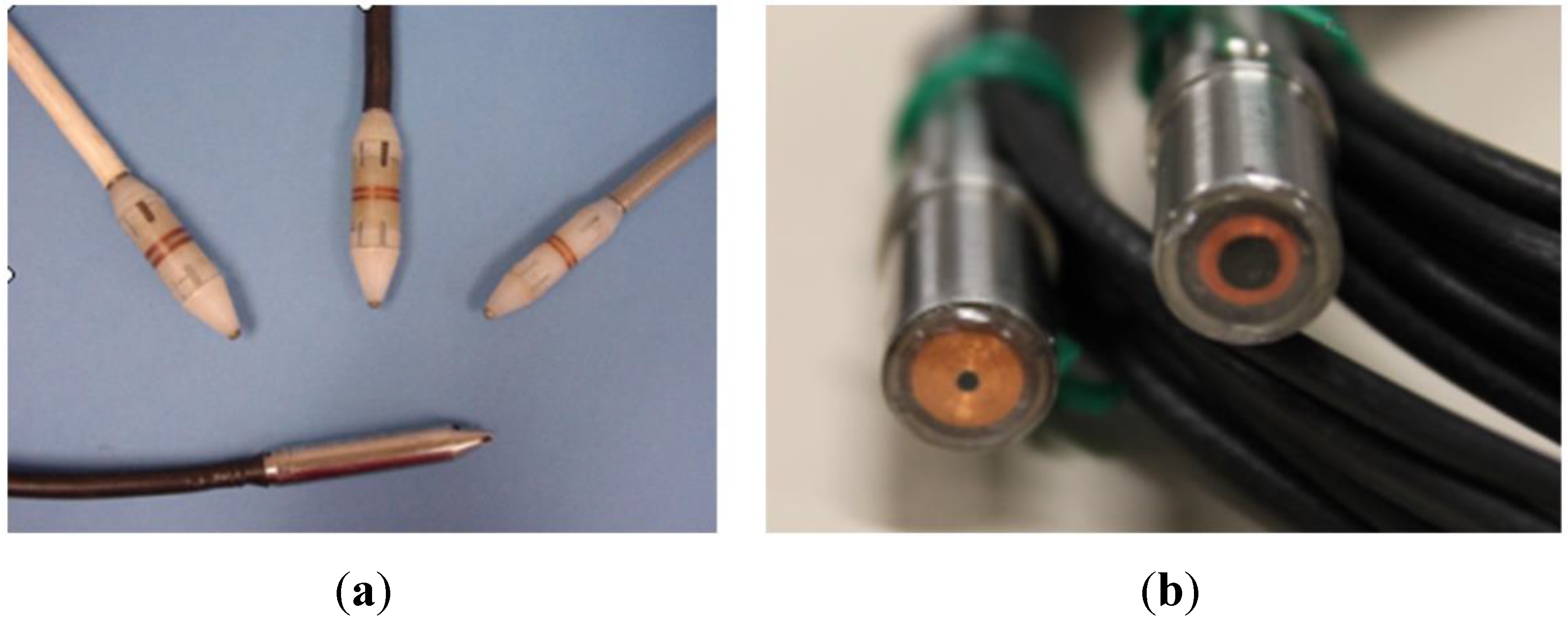
The test is performed with a bobbin coil that produces an electromagnetic field in the tube. This enhances the sensitivity of inspection of the inside diameter of a tube where defects are most likely to occur. By using multiple frequencies, 100% of a tube’s wall can be scanned to detect flaws at various depths. When the probe is moved across uneven surfaces, the electromagnetic field is distorted as a function of the size and location of the asperity relative to the probe. This distortion in the magnetic field alters the coil impedance relative to the asperity. This coupling effect of the eddy current probe with the material makes it essential that tubes be properly cleaned and their dimensions are known prior to inspection. The key to reliable detection of the extent and depth of such defects is correct selection of the probe material and precise calibration. Calibration must therefore be done with exactly the same material as that inspected later. Since they are accessible, tubes could be inspected from the inside. This is not possible in the receiver, however. That is why, the use of nondestructive testing (NDT) methods from the outside has been proposed in MAINBOT. This requires a different type of ET sensor. The sensor concept used in [
14] (in-service oxide layer measurement in fuel rods) was modified for the inspection of receiver tubes. High frequency and low frequency ET probes were designed to measure coating and tube thickness, respectively (see
Figure 2). Many other applications employ ET inspection from the outside surface (railway inspection, turbine and compressor blade inspection [
15],
etc.).
Figure 2.
(a) Conventional ET bobbin coil; (b) ET sensors proposed in MAINBOT.
Figure 2.
(a) Conventional ET bobbin coil; (b) ET sensors proposed in MAINBOT.
3. Climbing Robot Design
3.1. Robot Specifications
The climbing robot is designed to inspect vertical structures and can be deployed in different areas of the plant. The prototype climbing robot built is intended to inspect the tubes of a central tower CSP plant’s receiver.
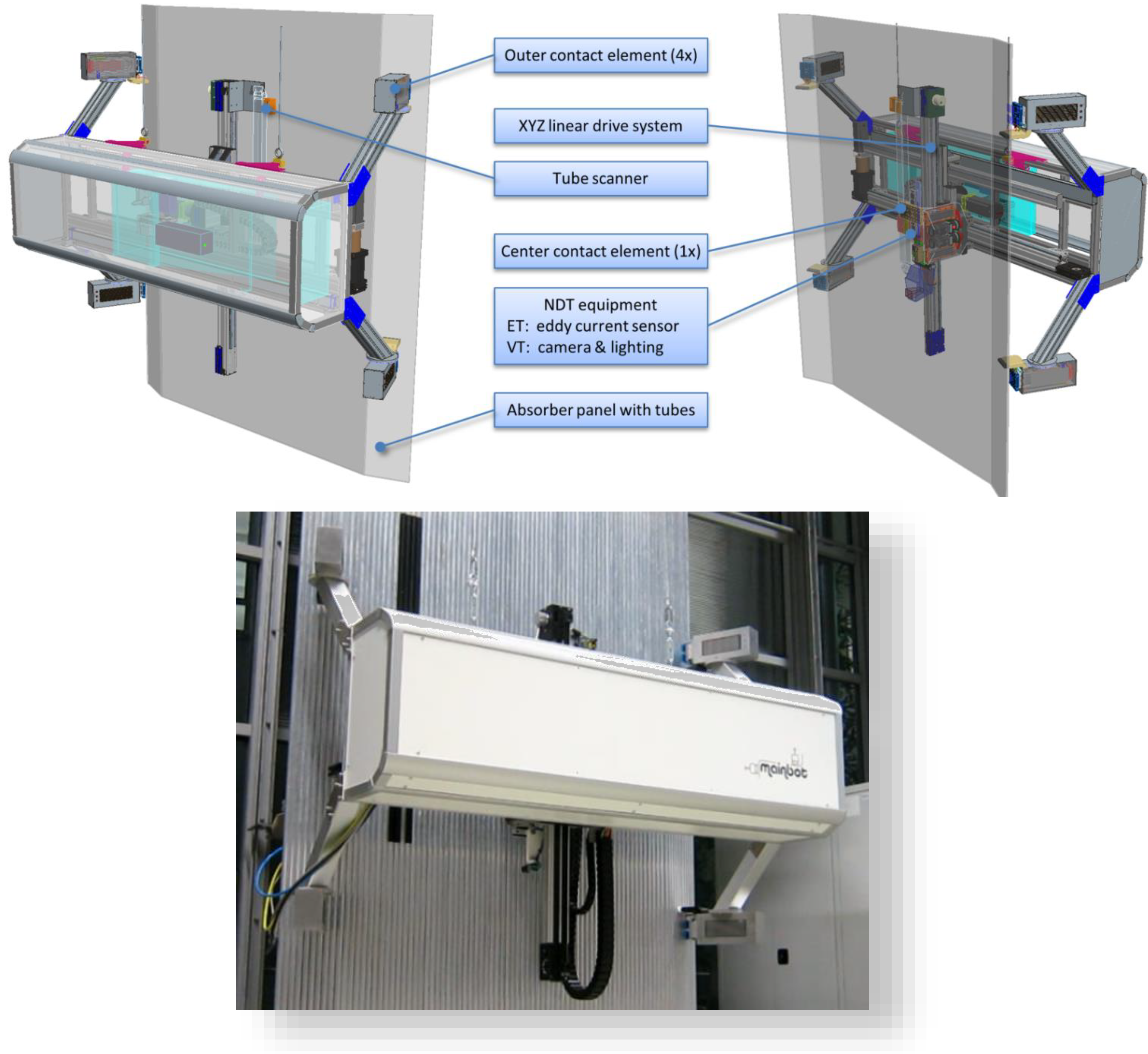
Figure 3 pictures the architecture of the climbing robot as well as the existing prototype. The climbing robot is moved vertically on the tower by the crane atop the receiver tower. The robot system includes a climbing mechanism that can be synchronized with the crane to bring the robot in the desired position. The robot is attached to the tower by arrays of vacuum suction cups. Four arrays are attached to the robot frame (the outer contact elements) and one array is integrated in the climbing mechanism (the center contact element). Since every climbing action entails aligning every one of the oval suction cups with the tubes of the panels, an optical sensor (tube scanner) scans the profile of the panel to determine the position of the tubes.
To implement the climbing robot design effectively, its movement and performance were simulated on a virtual tower model. The undercut of the panels on the receiver tower demands special attention when the inspection system is brought into the start position.
The features of the MAINBOT climbing robot are:
- -
robot weight: ~280 kg
- -
robot dimensions: 2.3 m × 1.6 m × 0.8 m
- -
high payload (only limited by the crane)
- -
obstacle navigation (climbing mechanism)
- -
adaptability to different surfaces, material and structures (interchangeable and adjustable contact elements)
- -
accurate tool (sensor) positioning thanks to servo controlled motion system
- -
fully and semi-automated operation modes with Web UI interface
- -
synchronized movement of robot and crane
Figure 3.
Service robot for absorber panel inspection (schematic view; picture of prototype).
Figure 3.
Service robot for absorber panel inspection (schematic view; picture of prototype).
3.2. Robot Climbing Mechanism
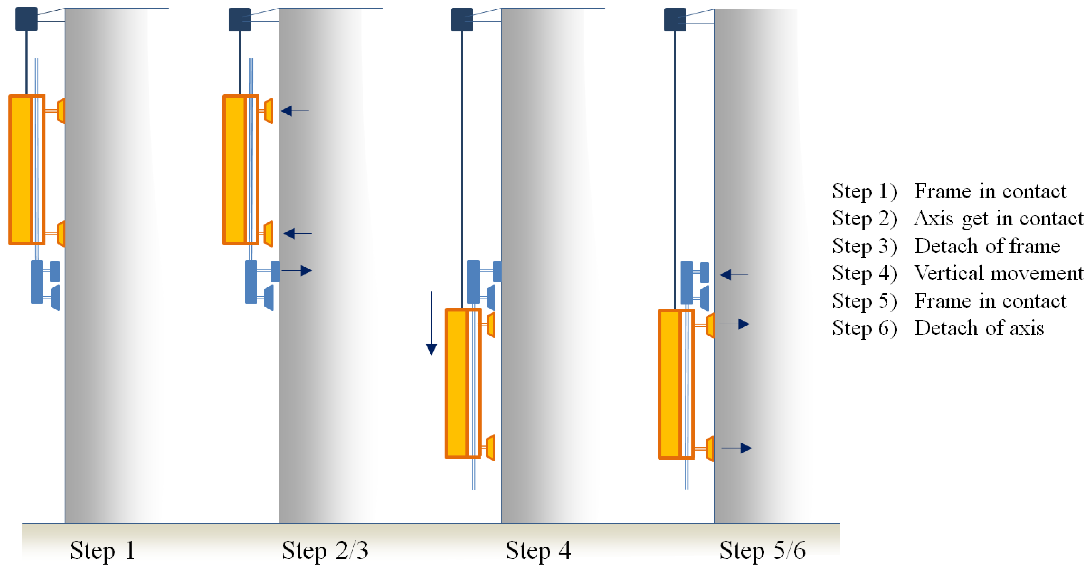
The robot includes a climbing mechanism with variable step size. The load of the robot is borne by the crane atop the tower (or the object being inspected). The robot is secured horizontally by its contact elements to prevent the system from swinging. The robot is in contact with both adjacent panels in order to leave one entire panel free for inspection.
The telescopic mechanism makes step width greater than the robot’s height. The climbing kinematics is also used to move sensors. The diagram below illustrates the robot’s climbing procedure (see
Figure 4).
Arrays of vacuum suction cups at the contact elements establish contact to the tubes of the receiver.
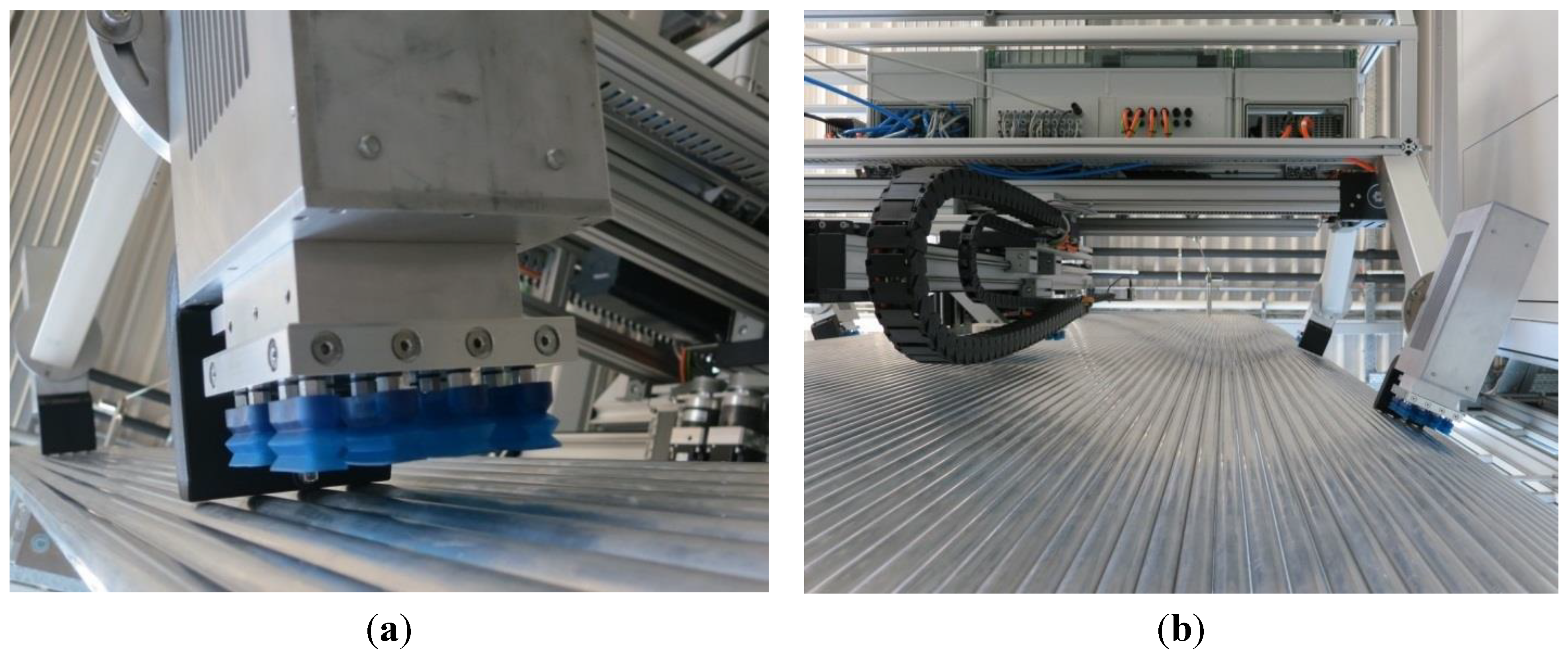
The outer elements are in contact with the adjacent panels during inspection. The vacuum grippers are aligned with the tubes automatically in a two-stage contact process. Soft bumpers at the elements ensure collision-free movement of the robot to protect the tube surface (see
Figure 5a). The contact with the adjacent panels leaves the entire area between the robot and the panel free, thus, allowing inspection by the NDT sensors (see
Figure 5b).
Figure 4.
Stepping procedure of the climbing robot.
Figure 4.
Stepping procedure of the climbing robot.
The central contact element can move in XYZ-direction relative to the robot frame. The element is in contact during vertical robot movement. A wire sensor measures any potential vertical deviation of the crane position and the vertical robot position, which can arise when their speeds differ. The position signal is used to synchronize the crane and the robot.
Figure 5.
(a) Contact element of the climbing robot; (b) Working area of the sensor system.
Figure 5.
(a) Contact element of the climbing robot; (b) Working area of the sensor system.
The performance of the climbing robot prototype was validated using an indoor mock-up of the receiver panel, which is composed of an array of aluminum tubes. Various tests were performed to validate the contact process, including the alignment method, the adhesion forces and the energy consumed to establish the vacuum.
Table 1 provides an overview of the maximum adhesion forces of each element in contact with the tube surface as well as the forces without vacuum contact and with contact to a flat surface. The forces without contact result from the minimal inclination angle of the winch rope.
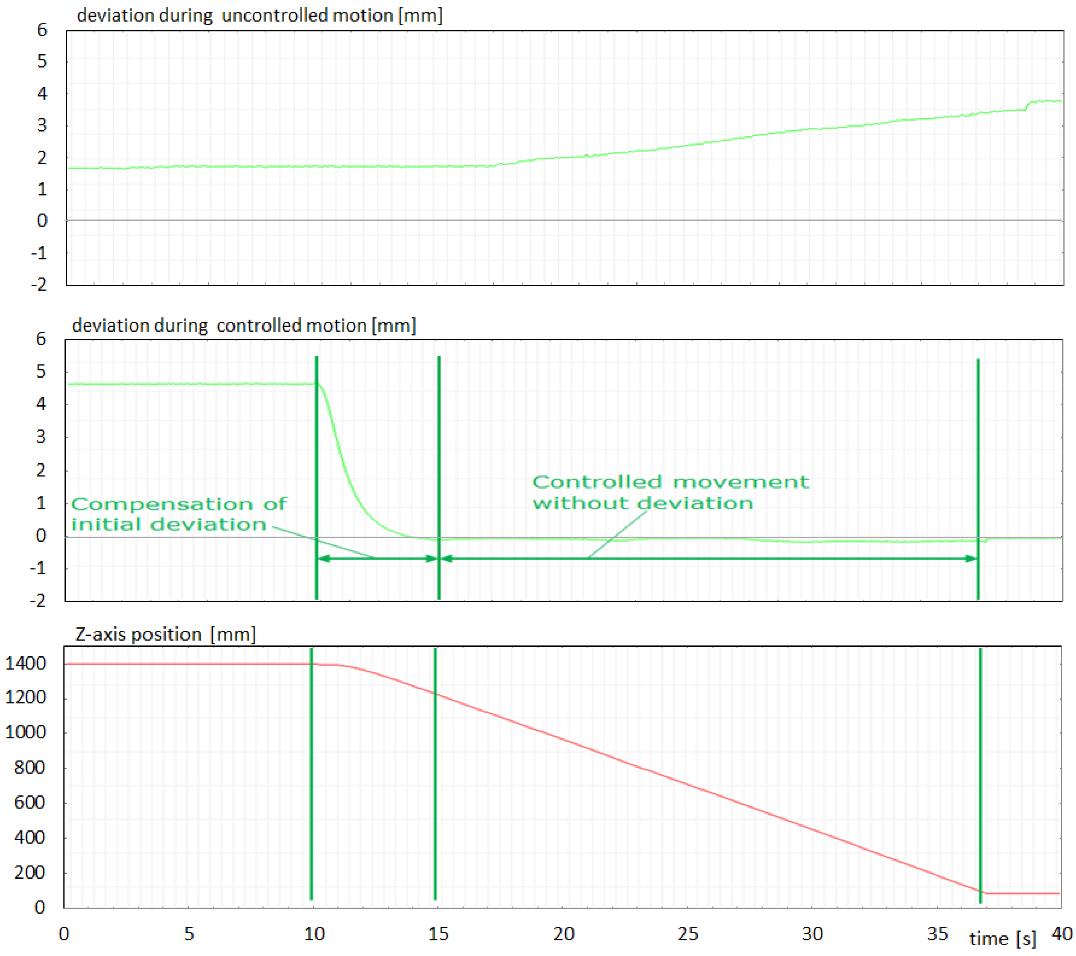
When it is moving vertically to the next inspection area, the robot’s central element is in contact with the panel. The robot runs in synchronous mode together with the winch.
Figure 6 compares uncontrolled and controlled vertical robot movement. The deviation between the robot’s vertical axis and winch position increases during uncontrolled vertical movement. Reasons for this are different target speeds and the swinging of the robot hanging from the winch. Uncontrolled movement is only possible for small vertical steps and only within the maximum range of deviation allowed.
Table 1.
Horizontal adhesion forces of the contact elements.
Table 1.
Horizontal adhesion forces of the contact elements.
| Holding Forces [N] | @ Contact Element |
|---|
| Top right | Top left | Down right | Down left | Center |
|---|
| without vacuum contact | 55 | 58 | 62 | 64 | 154 |
| vacuum contact with the tube surface | 209 | 223 | 209 | 214 | 365 |
| vacuum contact with a flat, homogeneous surface | 289 | 305 | 270 | 295 | 405 |
Figure 6.
Comparison of uncontrolled and controlled vertical robot movement.
Figure 6.
Comparison of uncontrolled and controlled vertical robot movement.
The control algorithm implemented compensates for the different speeds of the winch and the robot’s Z-axis. The speed of the robot axis (slave speed) is controlled as a function of the speed of the winch (master speed). Furthermore, any initial deviation is compensated within a short time. Several tests were performed at different speeds, in different directions and under different initial conditions to verify the control algorithm.
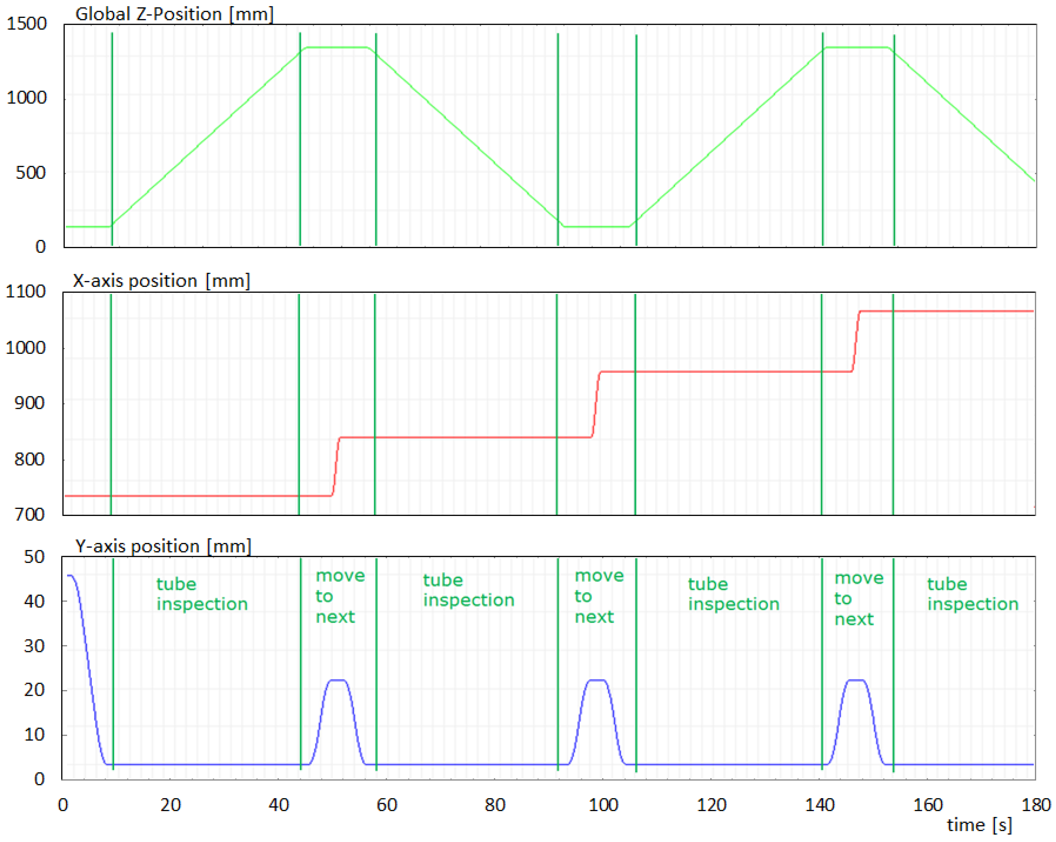
A typical motion sequence during the inspection of individual tubes is presented in
Figure 7. The total time required to inspect one panel area is about 27 min. Since increasing the climbing inspection speed is expected to reduce this time by as much as 50%, most of the individual robot actions were tested on the mockup at higher speeds.
Table 2 shows the time durations of individual robot actions and complete receiver inspection, comparing the measured values with the times after optimization.
Figure 7.
Robot movement during the inspection of the exchanger tubes.
Figure 7.
Robot movement during the inspection of the exchanger tubes.
4. Nondestructive Testing (NDT) of the Receiver Tubes
Two techniques are proposed for nondestructive inspection of the panels: visual inspection and eddy current testing. The first is used to assess coating degradation. Eddy current testing has the dual objective of measuring coating thickness and detecting internal corrosion (manifested as a reduction in tube thickness).
Table 2.
Total inspection times of the climbing robot.
Table 2.
Total inspection times of the climbing robot.
| Robot Operation | Time Duration [s] |
|---|
| | measured | after optimization |
| Move to panel | - | 300 (estimated) |
| Remove from panel | - | 300 (estimated) |
| Move to next area (performing one step) | 130 | 70 |
| sensor positioning | 15 | 5 |
| data acquisition (for tube section of 1.5 m): | | |
| paint layer thickness and internal assessment with ET | 50 | 25 |
| external assessment with video | 30 | 8 |
| move to next tubes | 10 | 5 |
| Inspection of complete GEMASOLAR receiver | | |
| with 2 sensors in parallel | 95 h | 50 h |
| with 8 sensors in parallel | 30 h | 16 h |
Tube inspection is quite common in nuclear power plants. Different eddy current sensors (bobbin coils, rotatory coils, etc.) are used to inspect in-service steam generator tubes periodically for degradation. These sensors are inserted in the tube and run along its whole length to detect stress corrosion cracking and other mechanical degradation modes that could cause tube failure. The inspection of fuel rods to measure oxide layers is another nuclear application in which eddy currents deliver the best performance. Specialized sensors are used to inspect them from the external surface. Comprehensive inspection of such components requires a combination of advanced probe technology coupled with versatile instruments and robotic systems controlled by fast computers and remote communication systems. The in-service inspection company and manufacturer of eddy current sensor and data acquisition systems, Tecnatom has contributed its extensive experience and know-how in this field to the MAINBOT project.
Visual cameras and eddy current sensors were integrated into the service robot to assess the degradation of the receiver tubes: The coating thickness (µm) is measured by the eddy current testing (ET) to detect diminished heat transfer performance. Furthermore, tube thickness (<3 mm) is also measured by ET to detect internal degradation of the tubes (corrosion, deposits,
etc.). A camera and lighting system (visual inspection or VT) detects external loss of coatings (≥3 × 3 mm).
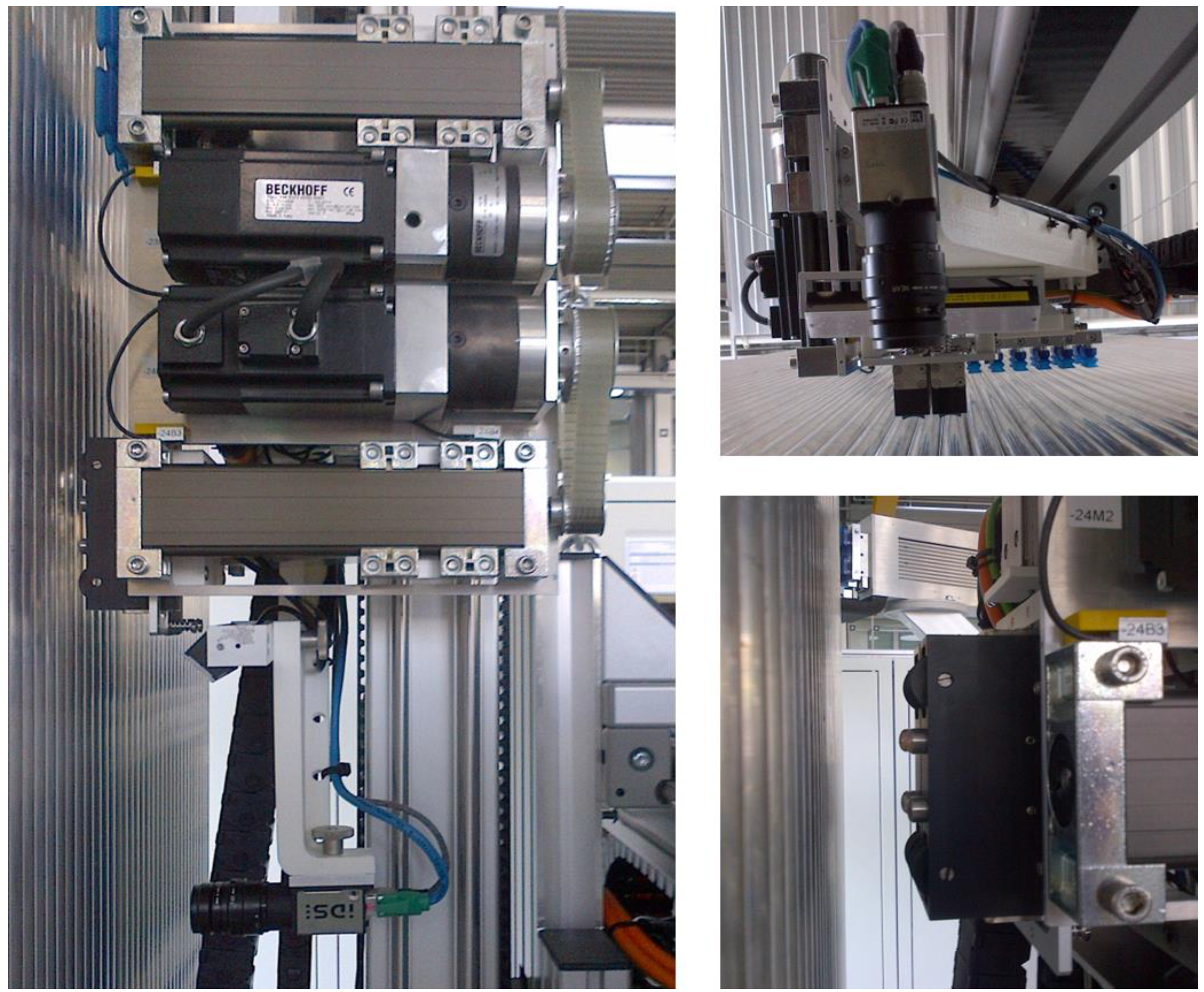
Figure 8 shows NDT instrumentation integrated next to the center contact element.
The robot’s climbing kinematics position the sensors along the tubes. The robot remains in its current position while on a tube area is being scanned and only proceeds to the next area afterward. An on-board PLC controls all functions of the robot.
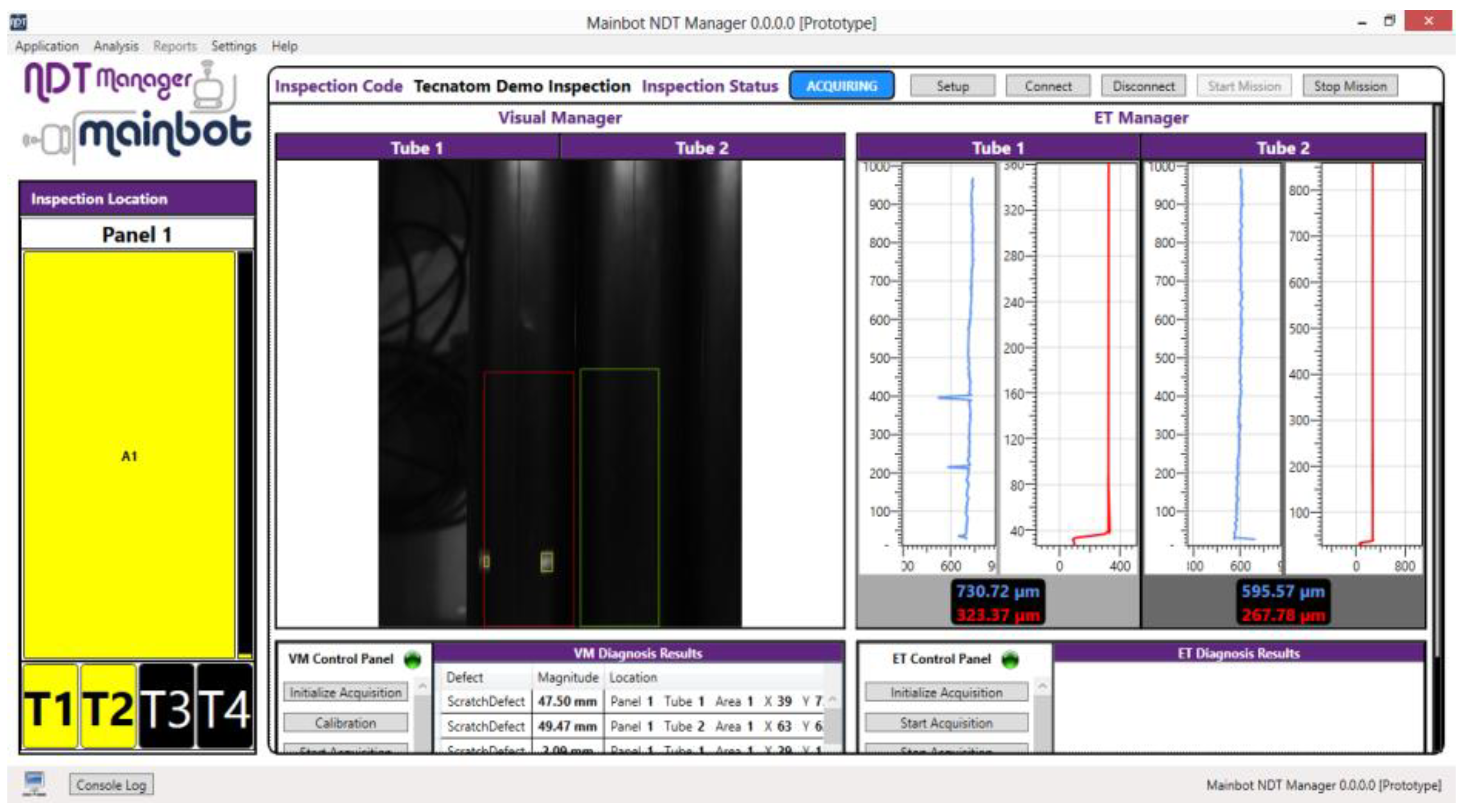
A higher-level control system is used to select the panel inspected and the inspection task. The General Control Manager uses Robot Manager software to command every robot movement and uses NDT Manager software to initiate NDT inspection. The individual inspection tasks, including on-line defect detection, are defined through the NDT Manager user interface and, then, executed automatically (see
Figure 9).
Figure 8.
NDT integration and central contact element.
Figure 8.
NDT integration and central contact element.
4.1. Eddy Current Testing of the Absorber Tubes
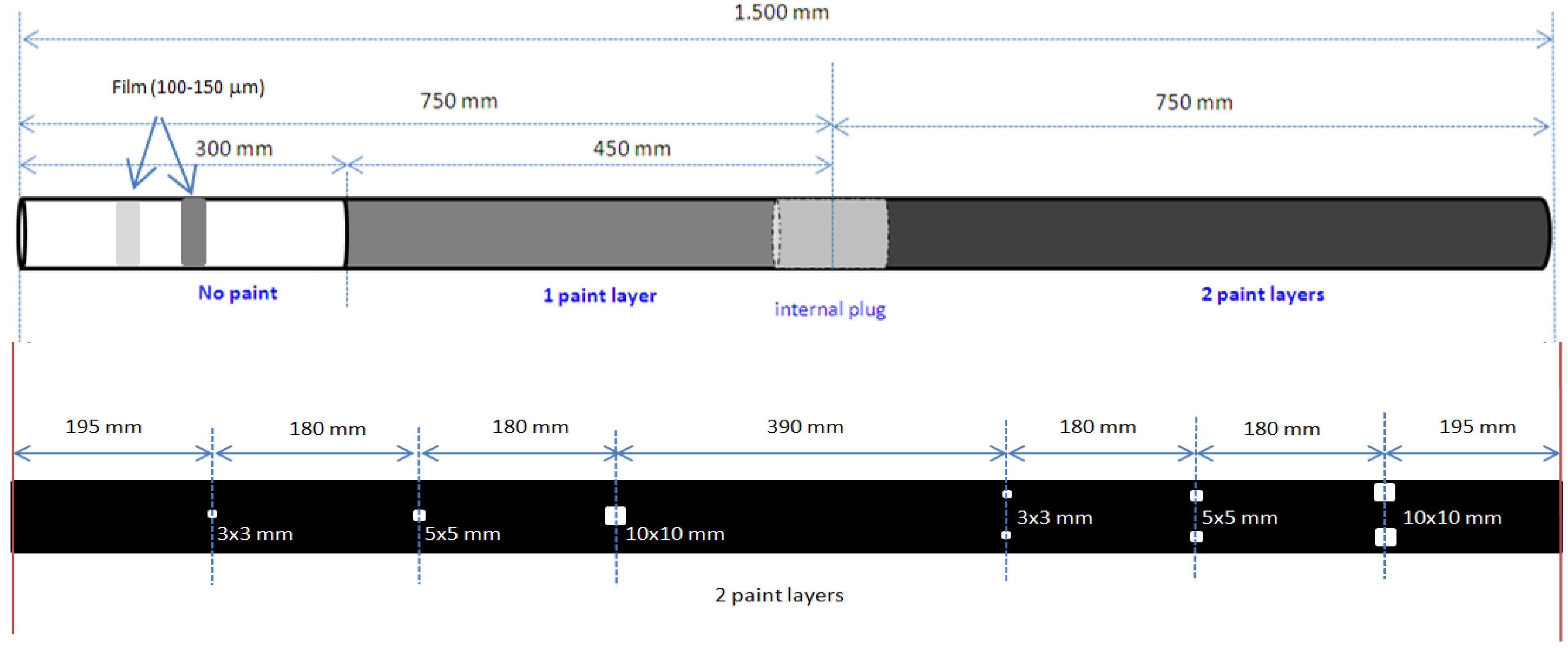
The ETbox2i containing all necessary ET hardware and software was developed by Tecatom. The main advantages of this system are its compatibility with different ET sensors, its automatic calibration of ET, and its online data processing on demand. All of the ETbox2i hardware has been optimized for size and performance. Two calibration tubes were made to test the coating sensors:
- -
The first tube has sections with different coating thicknesses (see
Figure 10, top).
- -
The coating in the second tube has been removed to reproduce defects of predefined sizes (3 × 3 mm
2, 5 × 5 mm
2 and 10 ×10 mm
2) in different locations (see
Figure 10, bottom).
Figure 10.
Calibration tubes for coating assessment.
Figure 10.
Calibration tubes for coating assessment.
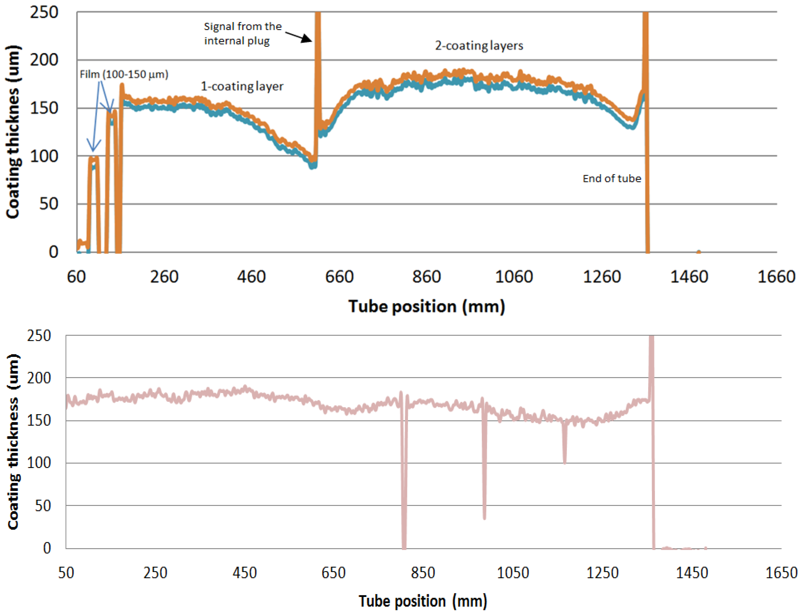
The coating measurements reveal varying thickness along the tubes (see eddy current inspection of calibration tube no. 1 in
Figure 11, top). Coating wear is only measurable when the ET sensor is perpendicular to the tube within a tolerance of ±30°.
Figure 11 (bottom) presents the results of the inspection of calibration tube no. 2, the defects introduced in the tube (see
Figure 10, bottom) being detected. Numerous tests validated the high precision of positioning and measurement.
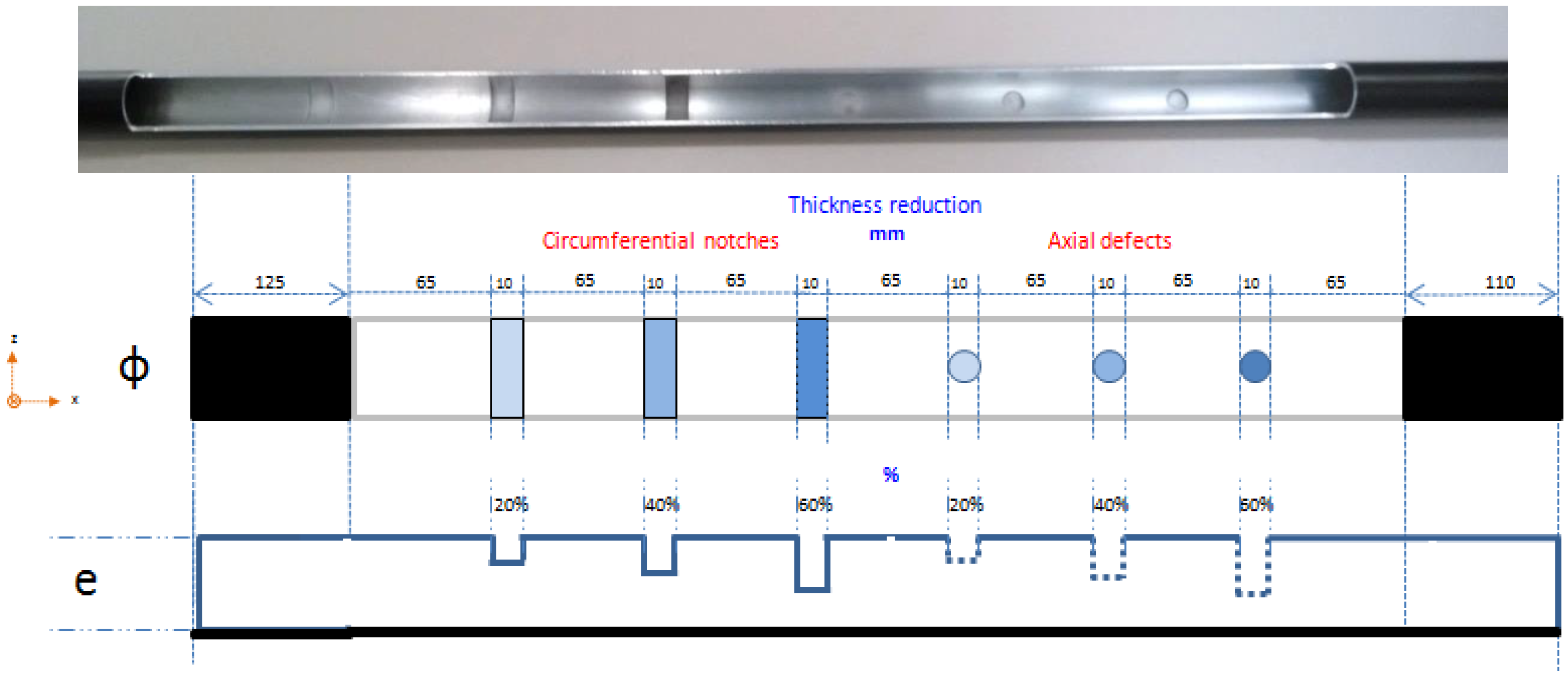
A calibration tube with artificial internal defects was made to facilitate their detection (two sets of EDM notches representing 20%, 40%, and 60% reductions of tube thickness, see
Figure 12).
The recorded ET data from the calibration tube are presented in
Figure 13. Low excitation frequencies are required to increase penetration. Moreover, raw ET data are processed online to calculate tube thickness, to stabilize ET signals and to eliminate the influence of coating. To do so, data are recorded at two frequencies, “f”, the optimum low frequency for the inspection of tube thickness, and “2f”, a higher frequency for the inspection of surface defects. The signals of both frequencies are combined by applying several algorithms that eliminate undesirable effects. Specifically, the frequency “f” detects the influence of coating, whereas the frequency “2f” detects both the interference of coating and surface defects. The coating signal has to be removed from the higher frequency “2f” in order to be able to characterize surface defects. To do so, the coating signal of the lower frequency “f” is rotated and rescaled to be equal to the coating signal of the higher frequency “2f”. The correct values of the rotation angle and the rescaling factor are computed using an optimization algorithm and a pure coating signal. The signal without coating influence is obtained by extracting to the higher frequency of “2f”, the rescaled and rotated version of the lower frequency “f”. The different properties of the magnetic field and the phase difference of the coating and tube surface guarantee that the processed signal only contains information on surface defects. Once they had been tested and validated, these algorithms were programmed in NDT Manager for automatic defect extraction.
Figure 11.
Coating measurements in calibration tubes.
Figure 11.
Coating measurements in calibration tubes.
Figure 12.
Calibration block for thickness measurement.
Figure 12.
Calibration block for thickness measurement.
Figure 13.
ET record with tube thickness measurements.
Figure 13.
ET record with tube thickness measurements.
4.2. Visual Inspection of Absorber Tubes (VT)
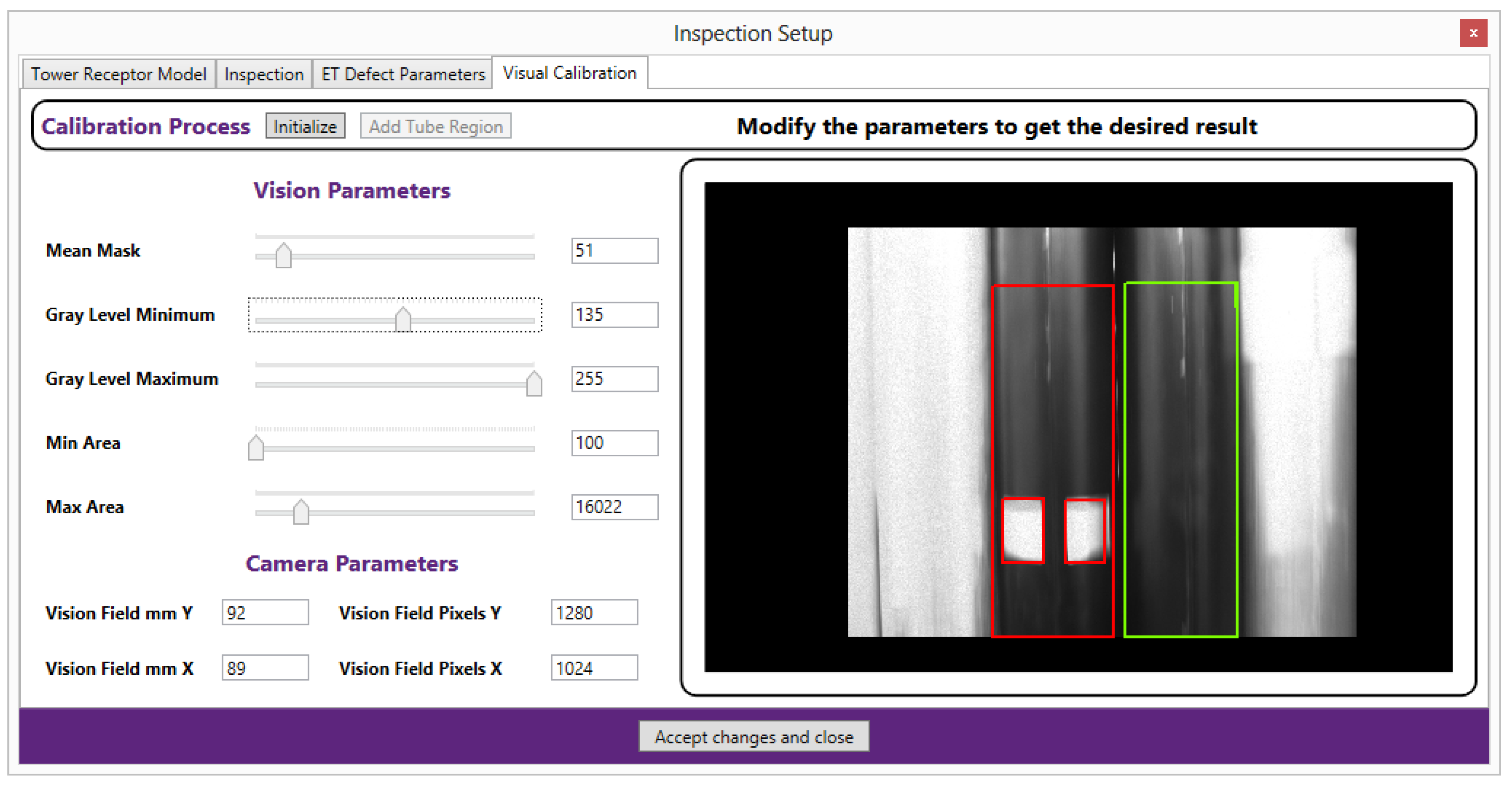
The camera and lighting device integrated in the climbing robot can inspect up to four tubes simultaneously. Since the ET module only inspects two tubes, the calibration process for the VT allows the user to:
- -
select the area of interest for image processing, thus automatically assigning detected defects specific tubes and keeping low quality areas of the image from being processed,
- -
adjust sensitivity for defect detection in terms of grayscale values and defect size (i.e., keeping defects smaller than 2 × 2 mm from being reported), and
- -
correct defect sizing, eliminating image distortions caused by tube curvature (
Figure 14).
Figure 14.
VT calibration process.
Figure 14.
VT calibration process.
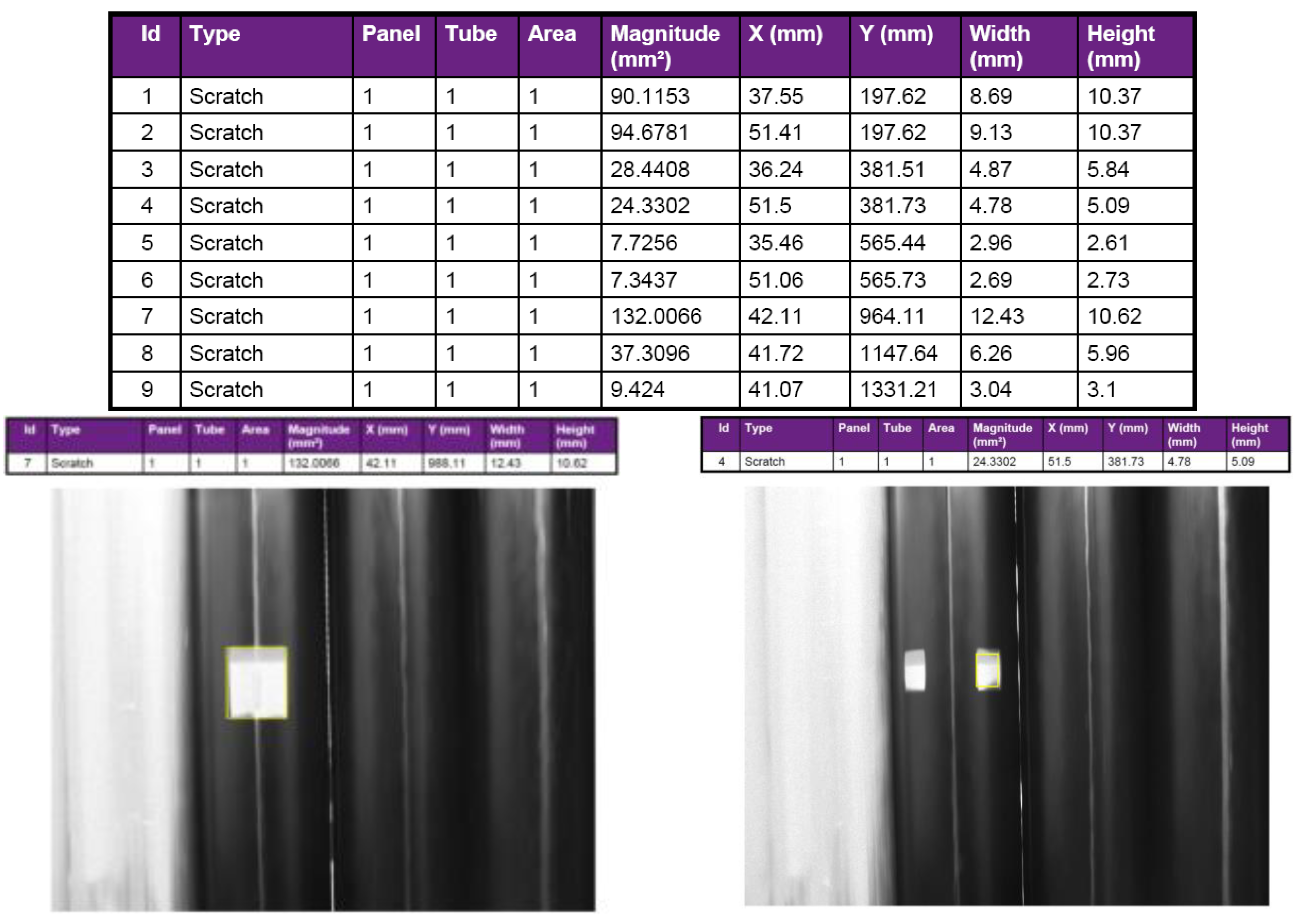
The camera effectively records the images and extracts the defects. The NDT Manager automatically generates reports with a table of defects and pertinent images (see
Figure 15).
Figure 15.
Automatic VT inspection report.
Figure 15.
Automatic VT inspection report.
5. Conclusions
This paper presents a prototype climbing robot that inspects vertical surfaces, specifically a heat exchanger in a central tower CSP plant. The robot uses customized contact elements with vacuum suction cups to establish contact with the tube structure. The unique method of alignment and contact makes it possible to secure the robot on the desired surface with specific tube characteristics. The integration of two major functions (climbing and sensor guidance) in the telescopic XYZ kinematics reduces robot complexity and increases the inspection area. The integrated measurement instrumentation assesses the degradation of the tubes. A new design is proposed for the ET sensors. New electronics (ETbox2i) for the data acquisition system are integrated in the robot. Dedicated software was developed for automated system calibration, for data acquisition synchronized with robot movement, and for automated defect extraction and characterization combining visual inspection and eddy current testing.
Initial results of tests of climbing action and NDT inspection with the prototype on a mockup are presented. Future work will improve the robot structure to satisfy every certification requirement, including the performance of robot tests under real conditions.
Service robots allow comprehensive evaluation of large industrial plants. The proposed robot system can inspect the surfaces and the internal structures of heat exchanger tubes. Other applications in addition to the use case of the climbing robot on the receiver in a central tower CSP plant are conceivable, e.g., tank inspection. Furthermore, the robot can also be used to inspect other objects, e.g., dams, bridges, facades, or similar structures. The fully automated inspection robot increases the efficiency of maintenance work, reduces operating and maintenance costs, and improves safety and working conditions for service technicians.
Acknowledgments
The research project “MAINBOT. Mobile Robots for Inspection and Maintenance in Extensive Industrial Plants” is being funded by the European Union in its Seventh Framework Programme FoF.NMP.2011–2013 under grant agreement no. 285245 [16].
Author Contributions
All authors contributed equally to this work. T. Felsch and G. Strauss developed and tested the climbing kinematics. C. Pérez and J.M. Rego developed and tested the NDT technology. T. Felsch and C. Perez wrote the main paper, and G. Strauss wrote the supplementary information. All authors discussed the results and implications and commented on the manuscript at all stages.
Conflicts of Interest
The authors declare no conflict of interest.
References
- Cho, K.H.; Jin, Y.H.; Kim, H.M.; Moon, H.; Koo, J.C.; Choi, H.R. Caterpillar-based cable climbing robot for inspection of suspension bridge hanger rope. In Proceedings of the 2013 IEEE International Conference on Automation Science and Engineering (CASE), Madison, WI, USA, 17–20 August 2013; pp. 1059–1062.
- Goldman, G.J. Design Space and Motion Development for a Pole Climbing Serpentine Robot Featuring Actuated Universal Joints. M.S. Thesis, Department of Mechanical Engineering, Virginia Polytechnic Institute and State University, Blacksburg, VA, USA.
- Fernández, R.; González, E.; Feliú, V.; Rodríguez, A.G. A wall climbing robot for tank inspection. An autonomous prototype. In Proceedings of the IECON 2010—36th Annual Conference on IEEE Industrial Electronics Society, Glendale, AZ, USA, 7–10 November 2010; pp. 1424–1429.
- Eich, M.; Vogele, T. Design and control of a lightweight magnetic climbing robot for vessel inspection. In Proceedings of the 2011 19th Mediterranean Conference on Control & Automation (MED), Corfu, Greece, 20–23 June 2011; pp. 1200–1205.
- Leon Rodriguez, H.; Sattar, T.; Park, J.O. Wireless climbing robots for industrial inspection. In Proceedings of the 2013 44th International Symposium on Robotics (ISR), Seoul, Korea, 24–26 November 2013; pp. 1–4.
- Wang, H.; Yamamoto, A.; Higuchi, T. Electrostatic-motor-driven electroadhesive robot. In Proceedings of the 2012 IEEE/RSJ International Conference on Intelligent Robots and Systems (IROS), Vilamoura-Algarve, Portugal, 7–12 October 2012; pp. 914–919.
- Menon, C.; Murphy, M.; Sitti, M. Gecko Inspired Surface Climbing Robots. In Proceedings of the ROBIO 2004. IEEE International Conference on Robotics and Biomimetics, Shenyang, China, 22–26 August 2004; pp. 431–436.
- Prahlad, H.; Pelrine, R.; Stanford, S.; Marlow, J.; Kornbluh, R. Electroadhesive robots—Wall climbing robots enabled by a novel, robust, and electrically controllable adhesion technology. In Proceedings of the IEEE International Conference on Robotics and Automation 2008 (ICRA 2008), Pasadena, CA, USA, 19–23 May 2008; pp. 3028–3033.
- Sack, M.; Elkmann, N.; Felsch, T.; Bohme, T. Intelligent control of modular kinematics—The robot platform STRIUS. In Proceedings of the 2002 IEEE International Symposium on Intelligent Control, Vancouver, Canada, 27–30 October 2002; pp. 549–553.
- Elkmann, N.; Felsch, T.; Sack, M.; Saenz, J.; Hortig, J. Innovative service robot systems for facade cleaning of difficult-to-access areas. In Proceedings of the 2002 IEEE/RSJ International Conference on Intelligent Robots and Systems, Lausanne, Switzerland, 30 September–4 October 2002; Volume 1, pp. 756–762.
- Guimaraes, M.; Lindberg, J. Remote controlled vehicle for inspection of vertical concrete structures. In Proceedings of the 2014 3rd International Conference on Applied Robotics for the Power Industry (CARPI), Foz do Iguassu, Brazil, 14–16 October 2014; pp. 1–6.
- Leibbrandt, A.; Caprari, G.; Angst, U.; Siegwart, R.Y.; Flatt, R.J.; Elsener, B. Climbing robot for corrosion monitoring of reinforced concrete structures. In Proceedings of the 2012 2nd International Conference on Applied Robotics for the Power Industry (CARPI), Zurich, Switzerland, 11–13 September 2012; pp. 10–15.
- Vázquez, J.; Guerra, F.J.; Vano, J. Automatic Process for Eddy Current Inspection of Steam Generator Tubes. In Proceedings of the 2nd International Conference on NDE in Relation to Structural Integrity for Nuclear and Pressurized Components, New Orleans, LA, USA, 24–26 May 2000.
- Fernández, J.R.; Guerra, F.J. Fuel Rod Inspection System, SICOM-ROD. In Proceedings of the 6th International Conference on NDE in Relation to Structural Integrity for Nuclear and Pressurized Components, Budapest, Hungary, 8–10 October 2007.
- Jansen, H. Eddy Current Testing: Profiled eddy current probes for complex shape inspection. In Proceedings of the 18th World Conference on Nondestructive Testing, Durban, South Africa, 16–20 April 2012.
- MAINBOT—Mobile Robots for Inspection and Maintenance Activities in Extensive Industrial Plants. Available online: http://www.mainbot.eu (accessed on 3 August 2014).
© 2015 by the authors; licensee MDPI, Basel, Switzerland. This article is an open access article distributed under the terms and conditions of the Creative Commons Attribution license (http://creativecommons.org/licenses/by/4.0/).


