1. Introduction
Teleoperation involves controlling, operating, and manipulating remote robots and/or systems, in hostile environments, or in helping humans to accomplish strenuous tasks [
1,
2,
3,
4]. Since its conception, teleoperation has been applied in various areas such as space exploration [
5], surveillance [
6,
7], volcano exploration, landmine detection [
8], search and rescue [
9], robotic surgery [
10,
11,
12], mobile robots [
13,
14,
15,
16], and dealing with corrosive and deadly materials or substances [
17]. The three main components of a teleoperation system are the master device, the remote or slave device, and the communication channel. Unilateral or bilateral teleoperation are two classifications of remote teleoperation. In unilateral teleoperation, the operator is not provided with force feedback from the slave device; rather, the operator uses visual and auditory cues of the slave device condition to supervise its interaction with the environment. In contrast, for bilateral teleoperation, the master device receives force feedback from the slave device. Force feedback enables the operator to “feel” the remote environment which enables improved manipulation and better monitoring of the interaction between the slave device and the environment [
18]. However, the presence of time delay in the communication channel connecting the master and remote robots threatens the quality of the force feedback provided in the bilateral teleoperation system. It was demonstrated in previous studies that the introduction of the modest time delay could cause the instability of a bilateral teleoperation system [
19,
20,
21,
22]. An example of a real-life application where the presence of time delay can be problematic is a teleoperated combat drone. The instability induced due to time delay of a fraction of a second in shooting a missile could cause that missile to hit the wrong target.
Several solutions to time delay induced instability in bilateral teleoperation were proposed in the literature. Leung et al. [
23], suggested a tunable H∞ optimal-based controller by which a teleoperation system can gain stability for a prescribed time delay margin, with more improvement presented by Sano et al. [
24]. Extending the work proposed by Anderson and Spong, Neimeyer and Slotine developed the wave variable method, which modeled the bilateral teleoperation system as an ideal power transmission line with a more mechanical formulation [
25]. The wave variable method assures the stability of the bilateral teleoperation system in the presence of any fixed time delay using passivity arguments. Nonetheless, the fixed time delay problem is still an important problem and recent research shows that [
26,
27,
28]. Shukla et al. [
26] designed a passive sliding mode controller that exhibits Real Time Cyber-Physical System characteristics for trajectory tracking of a mobile robot in the presence of fixed time delay and traffic disturbances.
However, the wave variable method exhibits several intrinsic drawbacks which include position drift, wave reflections, etc. Our focus in this paper is wave reflections. The wave variable method produces wave reflections when impedance mismatch occurs between the master and slave site, which can cause system performance to deteriorate [
29,
30,
31]. Sun et al. in [
32] conducted a comprehensive survey on wave variable controlled bilateral teleoperation systems. The authors claimed that wave reflections can be exposed by evaluating the standard wave-based teleoperation architecture. A wave controller-based teleoperation system can have three independent signal feedback channels. Channel 1 is made up of the feedback from the master in the form of the damping. In channel 2, the operator receives the feedback from the slave and channel 3 consists of the wave reflections. Wave reflections in channel 3 can degrade the information present in channel 1 and 2 if it is not removed. The continual reflection of the wave signal develops an oscillatory behavior of the bilateral teleoperation system which is a distraction to the system operator [
33]. We can compare these wave reflections to echoes generated in a deficient acoustic system. Tian et al. in [
34], evaluated wave reflection in the frequency domain and concluded that wave reflection occurs as a result of oscillation in the response of the teleoperation system.
Various approaches were suggested in the literature to attenuate the wave reflections that degrade teleoperation performance [
35,
36,
37,
38,
39]. Bate et al. in [
40] developed a wave-based method that can reduce wave reflections and maintain stability in teleoperation for unknown environments. This was achieved by altering the wave variables architecture without necessarily satisfying the impedance matching requirement while stability is guaranteed. Sun et al. in [
41] developed a four-channel (4-CH) architecture that made use of two modified wave transformation schemes for improving wave-based system transparency and assuring stability under time-varying delays. The two modified wave transformation schemes were implemented such that the feed-forward signals were encoded with the feedback signals. To address the issue of uncertainties in the system, a sliding mode control algorithm was implemented. With the modified 4-CH architecture, wave reflections were mitigated, the signal transmitted was improved while satisfying passivity argument. Zeng et al. in [
42] suggested a wave-based bilateral teleoperation approach using time domain passivity control to mitigate wave reflection and improve tracking performance. However, the two major categories for attenuating wave reflections are impedance matching and filtering techniques. Impedance matching is a technique in which the wave impedance of the master site is set to match the impedance of the slave site. This can be achieved when additional damping is introduced into the system [
30,
31,
43]. It is known that this approach attenuates wave reflections, yet it slows down the feedback coming from the remote site to the operator [
38]. Likewise, there can also be a difficulty in directly matching impedances because the knowledge of the impedance of the remote environment is required [
37]. Sometimes the remote site impedance changes continuously and/or it may be that the remote environment is inaccessible.
Filtering is another technique used in mitigating wave reflections. Previous works considered the time delay across the communication channel to be mainly associated with the frequency at which these wave reflections occur. First, Niemeyer and Slotine in [
44] suggested the use of low pass wave filters to attenuate wave reflections. Selecting the cutoff frequency of the low pass filter depends on the time delay across the communication channel. The drawback of implementing a low pass filter is that it gravely limits the system bandwidth, although it does decrease the wave reflection. Hirche and Buss in [
45] proposed developing filters in the frequency domain by implementing an optimization algorithm. The use of the algorithm requires prior knowledge of the system’s impedance, so it becomes more difficult when dealing with varying impedances. Kuschel in [
46] continued this work and introduced the use of a bank of filters with an impedance matching ability of several systems, using smoothing functions to alternate between different filters. Ye et al. in [
47] developed a wave variable-based approach that enhances the fidelity of haptic feedback and eliminates force reflection bias. To enhance the fidelity of haptic feedback, the passivity of the system diminishes. To guarantee the passivity of the teleoperated system, the authors implemented a low pass filter with a bandwidth that can be tuned.
Furthermore, Tanner et al. in [
38] proposed that only the resonant frequency should be targeted rather than implementing a low pass filter that limits the system’s bandwidth manipulation. The authors presented the infinite and finite shaping wave filters that depend on the time delay that exists in the communication channel. However, the shaping wave filters are inadequate when the frequency of wave reflection drift based on the changes to system dynamics of the teleoperated system. In our study, we discovered that changes in the dynamics (slave mass) of a teleoperated system can affect the frequency components of wave reflections. These frequency components consist of lower and higher orders that can drift based on the changes to system dynamics of the teleoperated system. Besides, we observed that the increase in slave mass increases the magnitude of the reflected signal of wave reflections. Despite the success of the shaping wave filters with respect to time delay, the method struggles when the size of the slave mass is increased. This is because the shaping wave filters mitigate wave reflections based on the time delay only without considering changes to system dynamics. Nonetheless, to our knowledge, no previous research has examined this problem.
In this work, we develop a wave-variable-based controller (bandstop wave filter). In addition, we experimentally verify that the technique can mitigate wave reflections in the presence of fixed time delay and changes to system dynamics of the teleoperated system.
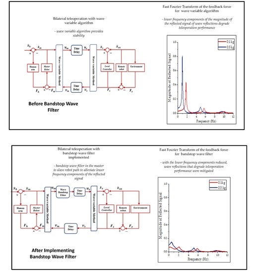
We apply the bandstop wave filter in the wave domain and filtered the wave signal along the communication channel. We placed the bandstop wave filter in the master-to-slave robot path to alleviate lower frequency components of the reflected signal. With the lower frequency components reduced, wave reflections that degrade teleoperation performance were mitigated and we obtained a better transient response from the system. Results from our experiment show that the bandstop wave filter performed better by 81% and 67% when compared to the traditional wave variable method and shaping wave filter respectively.
The rest of this paper is structured as follows. In
Section 2, we introduce the wave variable algorithm and the effect of wave reflection on teleoperation performance. In
Section 3, we discuss wave reflections and how their frequency characteristics can be affected by changing the slave mass. In addition, we present shaping wave filters one of the solutions proposed in the literature to address wave reflection. In
Section 4, we present the bandstop wave filters and its ability to attenuate wave reflections. In
Section 5, we illustrate the experimental setup and present our analyzed results. Finally,
Section 6 covers the conclusion.
2. Wave Variable Algorithm and Passivity
A bilateral teleoperation system with time delay across its communication channel gains stability when the wave variable algorithm is applied. In this section, we show how the wave variable provides stability to a bilaterally teleoperated system with time delay using passivity. In addition, we demonstrate the lingering effects of wave reflection on bilaterally teleoperated systems.
The wave variable method is implemented such that the power variables
and
are transformed into the wave variables
and
before being transmitted across the communication channel. We present the transformations as follows:
where
m represents master and
s represent the slave, and b denotes the characteristic wave impedance which for one degree-of-freedom is a positive constant, but it is a symmetric positive definite matrix for multiple degree-of-freedom [
48]. The transmitted wave variables are:
Figure 1 illustrates wave transformation following its implementation across the communication channel of a bilateral teleoperation system consisting of constant time delay
.
On arriving at the slave side of the teleoperation system, the wave variables are converted back to the following power variables:
The flow of power,
Pin(
t) into the communication channel can be expressed as [
25]:
Substituting (6), (7), (8) (9) into (10), the flow of power
is expressed as follows [
25,
35]:
Integrating the result obtained when Equation (5) is substituted into (11) and assuming
is zero, the energy stored when wave variable is implemented can be expressed as follows:
Hence, the stored energy is perpetually non-negative which guarantees the passivity of the communication channel when the wave variable algorithm is implemented.
Illustrated in
Figure 2a is the position, velocity, and force of a simulated bilateral teleoperation system whose master velocity was set to a step input of 0.05 m/s with a time delay of 100 ms. It is evident that the system is unstable because the position, velocity and force curve are unbounded. The system shown in
Figure 2b is the same as
Figure 2a but has the wave variable method implemented. In contrast to the unbounded behavior of the system in
Figure 2a, the system in
Figure 2b has a bounded behavior which implies that the system is stable. Although the wave variable algorithm could provide stability for teleoperation systems with time delay. Nonetheless, the algorithm produces transient oscillations, called wave reflections, which can degrade teleoperation performance as shown in
Figure 2b. Wave reflection can be generated in a bilateral teleoperation system when the incoming wave signals are being reflected. Another shortcoming of the wave variable algorithm is position drift error. Position drift caused by steady-state position errors due to integration because the encoded parameter in the communication channel is velocity and not position. However, in this paper, we focus on wave reflections.
4. Bandstop Wave Filter
In this work, we develop a wave-variable-based controller (bandstop wave filter). In addition, we experimentally verify that the technique can mitigate wave reflections based on the time delay and changes to system dynamics of the teleoperated system. We apply the bandstop wave filter in the wave domain and filtered the wave signal along the communication channel. We placed the bandstop wave filter in the master-to-slave robot path to alleviate lower frequency components of the reflected signal. With the lower frequency components reduced, wave reflections that degrade teleoperation performance were mitigated and we obtained a better transient response from the system. For a specific range of slave mass, the bandwidth of the filter can be determined. We provide experimental verification of this wave filtering technique using a tele-robot system consisting of two Force Dimension parallel manipulators in
Section 5.
From
Figure 4a, as the frequency components increase the magnitude of reflected signal reduces. Hence, a better transient response can be obtained from the system by alleviating lower frequency components. As a result, the bandstop wave filter is positioned between the master and slave devices such that the outgoing wave signal,
, is filtered as shown in
Figure 5. The filter can either be placed along with the master-to-slave device path or vice versa because the wave reflections circulate in both directions of the communication channel. The bandstop filter is not placed in the slave-to-master path, because the capability of implementing the bandstop on the master side (local site) is more feasible than the slave side. In the local site, the user can feasibly fine-tune the filter to mitigate wave reflections than to the remote site. The results of placing a filter on both the master-to-slave path and the slave-to-master path did not warrant the more difficult to implement placement on the slave-to-master path.
The bandstop wave filter transfer function can be expressed as [
36]:
denotes the lower cutoff frequencies and
denotes the upper cutoff frequencies. Choosing the filter cutoff frequencies depends on the minimum and maximum mass variations anticipated on the slave device. To determine the cutoff frequencies, we tested several percentages of the maximum magnitude of the reflected signal, ranging from 5% to 15%. However, 10% of the maximum magnitude of the reflected signal produced cutoff frequencies that alleviate wave reflections without the loss of important signals. Since the filter operates in the wave domain, Equation (21) can be described as the wave transfer function. It also represents the scattering operator since it illustrates the relationship between wave signals. The implementation of the bandstop filter into the bilateral teleoperation system does not jeopardize its passivity provided the wave transfer function is not greater than 1 [
29].
Equation (22) is true provided
from Equation (21). Equation (22) holds for (21) [
36]. This implies that the numerator
and denominator
satisfies
for
.
Simulation Results
In this section, we compared simulation results from traditional wave variable, shaping wave filter and bandstop wave filter. We set the command velocity of the master device to 0.05 m/s the same value used in
Section 3.3. The same teleoperator parameters presented in
Table 1 were used.
In
Figure 5, we implement the bandstop wave filter in the system illustrated in
Figure 3 to see its performance and the simulation results were presented. We applied a second-order Butterworth filter to annihilate the dominant frequencies of the wave reflections. The filter is made up of a high and low cutoff frequency of 2 Hz and 0.5 Hz respectively, giving a corresponding
and
of 12.57 rad/s and 3.14 rad/s respectively. These cutoff frequencies were chosen to alleviate wave reflections for slave masses 0.1 kg and 0.5 kg with a time delay of 100 ms.
In
Figure 6, we compare the performance of the bandstop wave filter to the shaping wave filtering technique. The dominant frequencies of the wave reflection were mitigated for all the simulated slave masses. From
Figure 4a, 0.81 is the highest magnitude when the traditional wave variable was implemented. The highest when the bandstop wave filter was 0.14 as shown in
Figure 6b. The magnitude of wave reflection decreased by 83% when the bandstop wave filter was used.
Comparing the performance of the shaping wave filter to the bandstop wave filter, it is apparent that the bandstop wave filter mitigates the dominant frequencies of the wave reflection more than the shaping wave filters. The highest reflected magnitude when shaping wave filter was employed is 0.45 as shown in
Figure 6a while 0.14 is the maximum when the bandstop wave filter was used as illustrated in
Figure 6b. The magnitude of wave reflection decreased by 69% from 0.45 when the shaping wave filter to 0.14 when the bandstop wave filter was used. Hence, the bandstop wave filter outperforms the shaping wave filter.
To substantiate our simulation results, we compared the performance of the traditional wave variable and shaping wave filter to the bandstop wave filter for 500 ms time delay in
Figure 7 and a worst-case simulation result of 5 s time delay in
Figure 8.
From
Figure 7a, the highest magnitude of the reflected when the traditional wave variable was used is 4.12. The shaping wave filter reduced the highest magnitude of the reflected to 1.44 in
Figure 7b. Implementing the bandstop wave filter, we were able to reduce the highest magnitude of the reflected to 0.41 as illustrated in
Figure 7c.
In
Figure 8, we provided a worst-case simulation for our proposed bandstop wave filter. 9.6 is the highest magnitude of the reflected signal when the traditional wave variable was used in
Figure 8a. With shaping wave filter, the highest magnitude of the reflected signal was reduced to 4.6 in
Figure 8b. With the bandstop wave filter implemented, we attenuate the highest magnitude of the reflected signal to 0.9 as illustrated in
Figure 8c.
5. Experimental Results and Discussion
We provide experimental verification of the wave filtering technique by implementing wave variable-based algorithms on a tele-robot system consisting of two Force Dimension parallel manipulators. Using the position, velocity and force feedback in the experimental results, we compare the bandstop wave filter with the traditional wave variable method and the shaping wave filter.
The master device used in this experiment is a three degree-of-freedom Force Dimension Omega.3 haptic device. This haptic device is a parallel linkage device that provides a closed-loop stiffness of 14.5 N/mm and forces up to 12 N. The slave device used is a Force Dimension sigma.7 with grasping force feedback of ±8 N. It is a seven degree-of-freedom parallel linkage haptic device that has a translational force and torque of 20 N and 0.4 Nm respectively. Both devices interacted via a software development kit called SDK through which the C++ code can be developed. All through the experiment, the slave mass remains fixed during motion and it is being changed only when the slave device is not in motion.
The experimental setup is pictured in
Figure 9. Engage the Omega.3 to start the experiment, then the slave device is displaced from its initial position of about −0.05 m from the origin frame to a new position where it is held for a few seconds after which it returns to its origin. On the slave site, a PD controller with proportional and derivative gains of 370 N/m and 2.5 Ns/m respectively is being used. A wave impedance, b, of 2.5 Ns/m is used. We perform this experiment for slave masses 0.1 kg and 0.5 kg. For each of the masses, the time delay of 100 and 500 ms was implemented for the traditional wave variable method, shaping wave filter and bandstop wave filter. Low pass and high pass filter cutoff frequencies for the bandstop wave filter are provided in
Table 2. The cutoff frequencies occur at about 10% of the maximum magnitude of the reflected signal. To demonstrate the effectiveness of the bandstop wave filter we compare its performance to that of the traditional wave variable method and the shaping wave filter.
To determine settling time when the bandstop wave filter and the shaping wave filter were employed, a step reference input was given to the master device and the response from the slave device was analyzed. The step-response starts at the time when the master device is displaced (). The settling time was determined when the response reach and stay within 2% of its final value. For each of the cases, we observed steady-state error in the system because velocity.
Instead of position is the parameter encoded before being transmitted across the communication link. The steady-state response of the slave device does not lie within the 2% of the desired steady-state value as shown in
Figure 10. However, to determine the steady-state value of the slave response we choose the tolerance to be 0.0001 which is two orders of magnitude smaller than 2%. The purpose of the tolerance is to create a limit to the deviation of the steady-state. On the slave response, wherever the value of the set gap is less than the tolerance as time goes to infinity is the steady-state value. We calculate the 2% of the determined steady-state value, the corresponding time minus the time at which the slave device was displaced is the settling time.
Table 3 illustrates the settling time for the bandstop wave filter and the shaping wave filter. Recall in
Section 3 that the shaping wave filters could alleviate wave reflections for limited cases. Therefore, for the slave mass of 0.5 kg at 500 ms, the settling time for the shaping wave filter remains unknown.
Figure 11 illustrates the experimental results when the slave mass is set to 0.1 kg and time delay to 100 ms. The trajectory plots for the traditional wave variable method, shaping wave filter and the bandstop filter are shown in
Figure 11a–c respectively. Wave reflections linger when the traditional wave method is implemented (
Figure 11a). The performance of the shaping wave filter is comparable with the bandstop wave filter. Recall that the shaping wave filter performs well in comparison to the bandstop wave filter for smaller slave masses because the frequency at which wave reflections occur for smaller mass can be estimated by just the time delay across the communication link. The slave device closely tracks the master device due to smaller mass and time delay in
Figure 11b,c. Wave reflections settle at 2.19 s for the bandstop wave filter 5.36 s for the shaping wave filter.
We present experimental results when the slave mass and time delay are set to 0.1 kg and 500 ms respectively as shown in
Figure 12. The trajectory plots for the traditional wave variable method, shaping wave filter and the bandstop filter are shown in
Figure 12a–c respectively. As time delay increases wave reflection becomes prominent, the period of oscillation grew longer and the gap between successive amplitudes became wider when the traditional wave variable method was implemented in
Figure 12a. With the bandstop filter implemented in
Figure 12c the wave reflections are attenuated at 12.41 s, while the shaping wave filter attenuated wave reflections at 17.68 s. Comparing the performance of the bandstop wave filter to the shaping wave filter for the slave of 0.1 kg and time 500 ms, evidently, the shaping wave filter took longer to attenuate wave reflections than the bandstop wave filter. Therefore, it can be said that the bandstop wave filter performed better than the shaping wave filter.
In
Figure 13, we present experimental results for slave mass and time delay of 0.5 kg and 100 ms respectively. The trajectory plots for the traditional wave variable method, shaping wave filter and the bandstop filter are shown in
Figure 13a–c respectively. The magnitude of the force feedback grew to about 2 N for a slave mass of 0.5 kg when wave variable was used in
Figure 13a and
Figure 14a while it was about 1 N for a slave mass of 0.1 kg in
Figure 11a and
Figure 12a. This occurs because the larger the mass, the higher the reflected signal and the lower the corresponding frequency components as noted earlier in
Section 4. The bandstop wave filter when used in
Figure 13c attenuated wave reflections at 3.52 s. We compare the performance of the bandstop filter to the shaping wave filter which attenuates wave reflections at 26.98 s when used in
Figure 13b. It is evident that the bandstop filter performs better, while it became difficult for the shaping wave filter to attenuate wave reflection due to the larger slave mass.
In
Figure 14a,b, the slave device could no longer track the master device due to larger slave mass and increases in time delay. The shaping wave filter struggles seriously for a larger slave mass of 0.5 kg with a time delay of 500 ms, while the bandstop wave filter attenuates wave reflections at 16.5 s. It is apparent that the bandstop wave filters outperformed both the traditional wave variable method and the shaping wave method for a larger slave mass of 0.5 kg with a time delay of 500 ms. Overall, the bandstop wave filter attenuates wave reflection faster than shaping wave filter for smaller or larger slave mass and time delay.
We present the experimental repeatability of the real master and real slave devices. An experiment is repeatable when the results of subsequent measurements closely agree with the results previously obtained under the same conditions [
51,
52].
In
Figure 15, we present a 95% confidence interval for each of the settling time obtained for the slave mass of 0.1 kg at a time delay of 100 ms and 500 ms. The 95% confidence interval provided a range of settling time within which wave reflections will be attenuated for each of the time delays. For time delay of 100 ms, we are 95% confident that the wave reflections will be mitigated between 2.19 s and 2.29 s when the bandstop wave filter is employed and, 5.27 s and 5.59 s when the shaping wave filter is used.
For a time delay of 500 ms, we are 95% confident that the wave reflections will be mitigated between 12.08 s and 12.84 s when the bandstop wave filter is employed and, 16.75 s and 19.01 s when the shaping wave filter is used. The margin of error increase as time delay increases for both the bandstop wave filter and the shaping wave filter. Also, the margin of error of the shaping wave filter is larger than the bandstop wave filter due to larger settling time. This means that the range of settling time at which wave reflections are attenuated is larger for the shaping wave filter compared to the bandstop wave filter. The bandstop wave filter is precise in attenuating wave reflections than the shaping wave filter.
6. Conclusions and Future Work
Here, we presented a bandstop wave filtering technique and experimentally verified its capability to improve teleoperation performance. The contributions of this research may be summarized as follows:
We developed a bandstop wave filter that can be applied in the wave domain for mitigating reflected wave signals along a communication channel of bilaterally teleoperated systems.
We were able to alleviate lower frequency components of reflected wave signals by placing the bandstop wave filer in the master-to-slave robot path.
With the lower frequency components reduced, reflected wave signals (wave reflections) that degrade teleoperation performance was mitigated and we obtained a better transient response from the system.
Although additional experimental testing may be needed to establish the full benefits of the bandstop wave filtering technique for teleoperation systems. Nonetheless, our experimental results provided evidence that the bandstop wave filtering technique may significantly improve teleoperation performance in applications including robotic surgery, search and rescue robots, teleoperated military combat drones, industrial robots, space exploration, etc.
The cut-off frequencies of the bandstop wave filter implemented in this work need to be tuned by the operator every time the range of slave mass changed. This is needful to target the most dominant frequencies of the wave reflections for the new range of slave mass. However, in the future, a self-tuning filter or adaptive filter that can mitigate wave reflections when the slave mass is change can be developed. To achieve this, the frequency of wave reflections can be determined based on the slave mass and implemented in the adaptive filter as a reference. Based on this reference, the adaptive filter will be able to tune itself to mitigate wave reflections.

 ,
, 


