Abstract
A high-fidelity 3D urban building model requires large quantities of detailed textures, which can be non-tiled or tiled ones. The fast loading and rendering of these models remain challenges in web-based large-scale 3D city visualization. The traditional texture atlas methods compress all the textures of a model into one atlas, which needs extra blank space, and the size of the atlas is uncontrollable. This paper introduces a size-adaptive texture atlas method that can pack all the textures of a model without losing accuracy and increasing extra storage space. Our method includes two major steps: texture atlas generation and texture atlas remapping. First, all the textures of a model are classified into non-tiled and tiled ones. The maximum supported size of the texture is acquired from the graphics hardware card, and all the textures are packed into one or more atlases. Then, the texture atlases are remapped onto the geometric meshes. For the triangle with the original non-tiled texture, new texture coordinates in the texture atlases can be calculated directly. However, as for the triangle with the original tiled texture, it is clipped into many unit triangles to apply texture mapping. Although the method increases the mesh vertex number, the increased geometric vertices have much less impact on the rendering efficiency compared with the method of increasing the texture space. The experiment results show that our method can significantly improve building model rendering efficiency for large-scale 3D city visualization.
1. Introduction
High-precision 3D urban models are an important source of data for smart city systems [1] which has been widely used in facility management, development planning, emergency decision making, and so on. As the 3D urban model from UAV oblique photography still has the disadvantages of structural adhesion, white holes, mesh distortions, and texture missing, a manual 3D model is still necessary [2,3]. The high-precision manual modeling method augments the reality of the scene at the cost of the rapid increase in the amount of data. Real-time rendering of a detailed 3D model is still a challenge for computer graphics [4]. As for a complex textured urban model, the amount of texture data is much larger than the geometric data [5]. It usually has dozens or hundreds of textures, which are characterized by large amounts but small individuals. Since each texture can be loaded and rendered very quickly, it is of little significance to simplify and compress a single texture, but for graphics processing unit (GPU) rendering, large quantities of small textures significantly increase the costs of loading and rendering batches, slowing down the rendering efficiency. Rendering a large-scale urban model scene directly is prone to slow model loading, untimely texture display, and rough roaming. Therefore, packing multiple textures into atlases for a 3D urban model can solve the rendering limitation.
Over the past few years, a great amount of research has been conducted on 3D model simplification. Some researchers studied geometric mesh simplification, which is mostly beneficial for finely tessellated and geometrically complex scenes [6,7,8]. As a 3D urban building model has the characteristics of non-manifold edges, footprint borders, and complex roofs, the mesh simplification method has to consider these features to preserve corner sharpness [9,10,11]. The Google Draco library is widely used for 3D model simplification, which compresses the mesh geometry and remaining texture mapping [12]. Other researchers studied texture simplification and composition. Since the amount of texture data is much larger than that of the geometric data for the complex urban model, texture simplification of the model is of great significance for data compression. Texture compression by reducing the texture size and quality can compress the amount of data [13], while it has a poor effect on the rendering efficiency and the visualization effect of the multi-texture urban model. Texture composition by packing all the textures into an atlas is widely used to reduce loading and rendering batches for the GPU [14]. For 3D urban models, tiled textures are more frequently used than non-tiled textures [15], such as walls, windows, and roofs. To achieve texture remapping, the texture atlas is usually processed in three ways. One way is to apply Render to Texture (RTT) technology to generate a projected surface atlas [16], which tends to reduce the texture accuracy. Another way is to add a repeating processed texture into the atlas, which greatly increases the amount of texture data. The third way is to pack the original textures into an atlas, which is the most widely used method. Some scholars studied repeated texture mapping for atlases through Shader programming [17,18,19]. These methods need more storage space between individual textures to avoid visual repeated line effects. In the meantime, the repeating method of the texture atlas by Shader programming is affected by the 3D graphic API, and the processed model can only be used for specific 3D software [5]. On the other hand, the traditional methods of the packed atlas size are uncontrollable [20]. For typical graphics hardware, the maximum texture size is limited to a supporting role. The texture atlas must be compressed below the maximum supported texture size, which inevitably reduces the model accuracy. In summary, the above texture composition methods cannot achieve the optimal combination for the texture atlas in terms of accuracy, size, and storage space.
In this paper, the challenges are addressed to realize the texture composition for an urban building model. A size-adaptive texture atlas generation and remapping method for a 3D urban building model is introduced, which can pack all the textures of a model adaptively without losing accuracy and increasing extra storage space. First, the individual textures of a 3D urban model are classified into non-tiled textures and tiled textures. Then, the multiple textures are packed into one or more texture atlases adaptively, depending on the maximum supported texture size of the graphics processing unit card. At last, the mesh of the model is reconstructed and mapped according to the original texture type of each triangle. For the triangle with the original non-tiled texture, new UV coordinates in the texture atlases are calculated, but as for the triangle with the original tiled texture, it is clipped into many unit triangles to apply the texture mapping method. Although the method increases the mesh vertex number, the increased geometric vertices have much less impact on the rendering efficiency compared with the method of adding extra texture storage space. Meanwhile, the Google Draco algorithm can be applied to compress the mesh geometry and remaining texture mapping. To test the performance of our multi-texture composition method, comprehensive experiments using real data are conducted. Single building models and large-scale urban scenes are tested for their rendering efficiency and effect. The experiment results show that our method can pack all the textures of a 3D urban model with lossless accuracy and significantly improve the rendering efficiency of the large-scale urban scene.
This paper is organized as follows. In Section 2, an overview of the texture atlas processing framework is presented. In Section 3, the texture atlas generation and remapping methods are explained in detail. In Section 4, we conduct a complete experiment for this method and analyze the experimental results. Finally, conclusions are drawn and future work is planned in Section 5.
2. System Framework
Figure 1 shows the workflow of the texture atlas generation and remapping method. The core idea of the method is to pack all the textures with optimal storage space and maintain the texture accuracy. For a typical urban model, the specific processes are as follows:
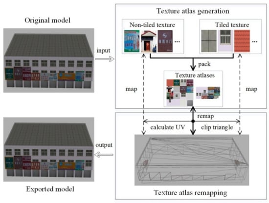
Figure 1.
Texture atlas generation and remapping workflow.
- (1)
- Extract model data and classify the textures. The textures and geometric mesh are extracted from the model, and all the textures are classified into non-tiled textures and tiled textures;
- (2)
- Set the maximum texture size and pack all the textures. The maximum supported rendering texture size is acquired according to the graphics processing unit card, and all the textures are packed into one or more texture atlases by the improved lowest horizontal search and simulated annealing algorithms;
- (3)
- Remap the texture atlases onto the geometric mesh. For the triangle with the original non-tiled texture, the new texture coordinates in the texture atlases can be calculated and set to the mesh directly. However, for the triangle with the original tiled texture, the corresponding mesh triangle is clipped into many unit triangles, and each one is remapped using texture mapping as the triangle with the original non-tiled texture;
- (4)
- Export the new model with the texture atlases.
3. Methodology
The main processing steps of the method include texture atlas generation and texture atlas remapping.
3.1. Texture Atlas Generation
The texture atlas generation problem is known to be NP-complete [21,22]. Computational geometry methods [23,24,25] perform well in terms of unused space, but they are not efficient enough for large urban data sets. The lowest horizontal search algorithm is relatively simple and efficient, but it does not take into account the rectangular size difference, which tends to leave blank space [26]. Considering the texture features of 3D urban building models, the improved lowest horizontal search and simulated annealing algorithms are combined to pack all the textures into one or more texture atlases optimally.
3.1.1. Multi-Texture Packing
The lowest horizontal search algorithm refers to updating the horizontal line to create a strip and insert the textures into the strip, as shown in Figure 2. Considering the limitation of the maximum texture size, the algorithm is improved to pack textures into one or more atlases adaptively.
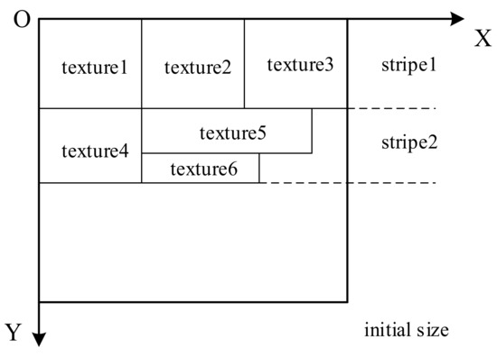
Figure 2.
Multi-texture packing sketch map.
As for a building model, the original textures are described as . The width and height of the i-th texture Ti are wi and hi, respectively, so the total texture area is . According to the maximum size of the supported texture of the graphics processing unit card, the textures are packed into n texture atlases, described as . The width and height of the i-th texture atlas Ai are Wi and Hi, respectively, so the total area of the texture atlases is . The following equation is for obtaining the maximum proportion value:
As shown in Figure 3, the specific steps of the texture packing algorithm include the following:
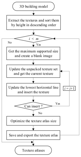
Figure 3.
Multi-texture packing flow chart.
- (1)
- Traverse the height value of all the textures and sort them in descending order. For textures with the same height, sort them in descending order based on the width value;
- (2)
- Get the maximum supported atlas size and create a blank image. The initial size is set to be the maximum supported texture size, such as 4096;
- (3)
- Set the initial horizontal line and iteratively insert the textures into the atlas. The height of the first horizontal line is set to be the height of the first sorted texture. For the i-th texture Ti, it is inserted into the atlas if possible. Otherwise, other textures are checked and inserted into the atlas. is used to update the packing state, where T stands for the unpacked textures and A stands for the texture atlases;
- (4)
- If no texture can be inserted into the current strip, the height of the horizontal line is updated. It is equal to the horizontal height plus the height of the current texture to be merged. Then the processing step goes to step 3 to constitute another stripe;
- (5)
- If the atlas cannot be inserted and the unpacked texture exists, a new blank atlas is created. Then, the processing step goes to step 2 to constitute another atlas;
- (6)
- The height of the last atlas is set to be the height of the horizontal line;
- (7)
- Export the texture atlases.
3.1.2. Atlas Optimization
Since the lowest horizontal search algorithm only achieves the local optimum, the simulated annealing algorithm is combined with it to make the packed texture atlases reach the global optimum. Simulated annealing (SA) is a stochastic approach that simulates the statistical process of growing crystals using the annealing process to reach its global minimum internal energy configuration [27]. The temperature formula is set to be , the initial temperature is T0, and the minimum temperature is Tmin. The specific steps of the simulated annealing algorithm include the following:
- (1)
- Attain the packed texture atlases by the lowest horizontal search algorithm as the initial solution X0;
- (2)
- Randomly swap the orders of two textures in step 1 in Section 3.1.1, pack the textures using the lowest horizontal search algorithm, and attain the current solution X1;
- (3)
- Calculate the value difference . If , X1 is accepted as a more optimal solution for texture packing. Otherwise, check . If this is true, X1 is accepted and set to . If this is not true, proceed to step 4;
- (4)
- Set and repeat steps 2 and 3 until ;
- (5)
- Export the optimal texture atlases.
The parameter r is an empirical value ranging from 0 to 1. If r is large, the probability of searching for the global optimal solution is higher, but the searching process time is longer. Otherwise, if r is small, the searching process will be fast, but it may eventually reach a local optimum.
3.2. Texture Atlas Remapping
As all the textures of a building model are packed into one or more texture atlases, the texture atlases must be remapped onto the geometric mesh. The texture atlas remapping problem is calculating the new texture coordinates for each triangle mesh. Figure 4 shows the texture atlas remapping sketch map.
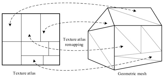
Figure 4.
Texture atlas remapping sketch map.
3.2.1. Non-Tiled Texture Remapping
For the geometric triangle corresponding to the original non-tiled texture, the new texture coordinate for the atlases can be calculated directly. The relationship of the original textures and the atlases is described as . As shown in Figure 5, the original texture coordinate of a vertex in the geometric triangle ABC is (U0, V0). The original texture is packed into the atlas in the position of (u, v). The width of the original texture is w, and the height is h. The width of the texture atlas is W, and the height is H. Therefore, the new texture coordinate of the part in the atlas for the triangle ABC can be calculated as follows:
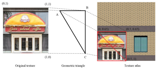
Figure 5.
Non-tiled texture remapping.
The coordinate (U, V) is the new texture coordinate of the vertex corresponding to the atlas. The texture coordinates for the three vertices of triangle ABC can be computed, which realizes non-tiled texture remapping.
3.2.2. Tiled Texture Remapping
A tiled texture is also called a repeated texture, which indicates that the texture coordinate is larger than one. The current 3D graphics API is designed to repeat the entire texture. Once the original tiled texture is packed into the texture atlas, the triangle cannot repeat the texture anymore. In order to keep the combined texture size optimal, the geometric triangle corresponding to the original tiled texture is clipped into many unit triangles for texture mapping.
Rectangle Clipping
Figure 6 shows the method of clipping the geometric triangle using the unit rectangle. O-XYZ is the 3D global geometric Cartesian coordinate system, the triangle in the global coordinate system is ABC, and its vertex coordinates are (Xa, Ya, Za), (Xb, Yb, Zb), and (Xc, Yc, Zc). Meanwhile, o-uv is the 2D local texture coordinate system, the triangle in the local coordinate system is abc, and its texture coordinates are (ua, va), (ub, vb), and (uc, vc). The triangle is clipped into many unit triangles in the 2D texture coordinate system, and the geometric vertices of the unit triangles are calculated in the 3D Cartesian coordinate system. The specific steps of the triangle clipping algorithm include the following:
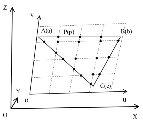
Figure 6.
Rectangle clipping.
- (1)
- Extract the geometric coordinates and original texture coordinates of each vertex in the triangle;
- (2)
- In the 2D texture coordinate system, the unit rectangle is used iteratively to cut triangle abc. It is clipped into many small triangles. The texture coordinate of each new vertex can be calculated, which is described as . The vertex p is the created vertex in the 2D texture coordinate system, and the texture coordinate corresponding to the original texture can be divided into two cases;
- (a)
- The vertex p is located inside triangle abc, so the texture coordinate of vertex p corresponding to the original texture can be calculated:
- (b)
- The vertex p is located on the edge of triangle abc. Assuming that vertex p is located on the edge ab, it can be divided into two situations. One situation is that vertex p is located on the m-th column line, so the texture coordinate of vertex p corresponding to the original texture can be calculated as follows:
Another situation is that vertex p is located on the n-th row line, so the texture coordinate of vertex p corresponding to the original texture can be calculated as follows:
- (3)
- Calculate the geometric coordinates of the created vertices. The geometric coordinates of the created vertices are described as . As we know, the 2D texture coordinates can be projected to the 3D Cartesian coordinate system to calculate the geometric coordinates, with geometric vertex P corresponding to texture vertex p. A Bursa-Wolf Seven-Parameter Transformation [28] is applied to compute the geometric coordinates of the new vertices. The geometric coordinates of vertex P can be calculated as follows:where is the geometric coordinates corresponding to the texture coordinate system origin o, U and V are the texture coordinates of vertex P, and are the direction factor, and scaleX and scaleY are the scale factors.
Texture Mapping
Since the geometric triangle is clipped into many unit triangles, texture mapping can be applied to the texture atlases. As shown in Figure 7, vertex P is the new vertex clipped by the n-th row and m-th column of the unit rectangle. The original texture coordinate of vertex P is , so the new texture coordinate of vertex P for the texture atlas can be calculated as follows:
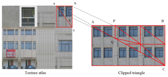
Figure 7.
Clipped triangle remapping.
Since the texture coordinates and the geographic coordinates of vertex P and Q are acquired, the new triangle APQ is built. Other new vertices and triangles can be constructed in the same manner. By clipping triangles and adding geometric vertices, the problem of repeated texture mapping is solved. The texture atlases are remapped in this manner.
4. Experiment and Discussion
To test the performance of our multi-texture composition method, comprehensive experiments using real data were conducted. The test area was in the city of Huaibei in China. The longitude of the extent ranges from 116.7632° to 116.8391°, and the latitude ranges from 33.9397° to 33.9823°. The original format of the experiment data was a Max file, and the amount of data was 12.1 GB. The size-adaptive multi-texture composition tool was programmed in C++ and C#. It applied the Assimp [29] library to load and convert the model files. The urban models were converted to GLB format and organized into the 3DTiles format [30]. For the large-scale urban model scenes, Tomcat was used to publish these model data, and the open-source web 3D library Cesium [31] was applied to render the urban models. The Google Chrome browser was used to explore the model scenes. The reported results were measured on an Intel Core i5-6400 @2.70 GHz (4 CPUs) PC with 8GB of core memory and an NVIDIA GeForce GT 730 with 1GB of memory.
4.1. Experimental Results
In order to efficiently load and render the massive high-precision building models, the files were processed and organized appropriately. The processing workflow is shown in Figure 8, the specific steps were as follows:
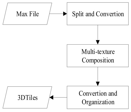
Figure 8.
Processing flow of urban models.
- (1)
- Extract the urban scene from the Max file;
- (2)
- Split the scene into many individual building models and convert them into OBJ format;
- (3)
- Pack the multi-textures into the texture atlases and remap them onto the geometric mesh for each building model;
- (4)
- Convert the models into GLB format and organize them by the 3DTiles format;
- (5)
- Load and render the urban scene in Cesium.
Figure 9 shows the textures of a building model before and after processing. Figure 9a shows 95 textures of the original model, including non-tiled textures and tiled textures. The maximum texture size was set to be 2048, so all the textures were packed into 4 texture atlases as shown in Figure 9b. The number of textures was significantly reduced by texture packing. The original geometric mesh is shown in Figure 10a, and it was clipped for texture atlas remapping as shown in Figure 10b. Through the comparison, it can be seen that the number of geometric vertices increased after the texture remapping. Figure 11a is the visual effect of the original model, and Figure 11b is the visual effect of the processed model. Compared with the original model, the visual accuracy of the texture-packed model was almost the same.
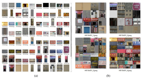
Figure 9.
Texture mapping: (a) original texture and (b) texture atlas.
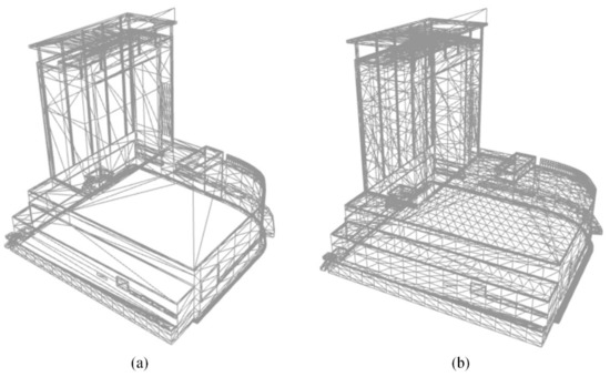
Figure 10.
Geometric mesh: (a) original mesh and (b) clipped mesh.
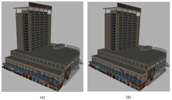
Figure 11.
Textured model: (a) original model and (b) processed model.
The texture-packed building model was loaded and visualized in Cesium as shown in Figure 12. It can be seen from the figure that the rendering effect of the model after texture processing was good. The visual repeated line effect did not exist on the 3D building model’s surface. The visual effect of the texture-packed model met the actual demand. This shows that the method in this paper can achieve texture packing and remapping for 3D urban building models.
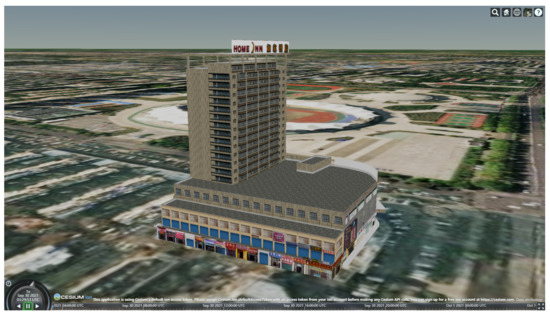
Figure 12.
Textured model rendering in Cesium.
Table 1 shows the data comparison results before and after texture packing for three urban models of different complexities. The original and processed models were compared in GLB format. The multi-textures were packed without image compression, and the geometric mesh was clipped for texture atlas remapping. By comparing the data before and after processing of the same 3D urban building model, it can be found that the number of textures decreased, and the number of geometric vertices increased after texture packing, but the storage size of the model file decreased. Although more vertices were generated after the geometric mesh was clipped, the vertex storage was efficient, and the increased storage space was limited. Meanwhile, the geometric mesh of the model could be further compressed by the Google Draco algorithm. The processed model with added vertices was simplified more efficiently than the original model. As a result, the processed model’s file was smaller than the original model’s file.

Table 1.
Comparison of single models.
Since a single building model file size is relatively small, the large-scale urban scene was tested for its rendering frame rate. All the building models were processed and organized into 3D Tiles format by a quadtree index, which was loaded in Cesium as shown in Figure 13. Compared with the original urban scene, the texture-packed urban scene was loaded and rendered faster. The reasons for this include two points: (1) the building model was packed with fewer textures, which decreased the texture loading and rendering batches, and (2) the file size of the processed model was smaller, which decreased the loading time. When comparing the rendering smoothness of the urban scene, the rendering of the original 3D scene was not smooth, while the rendering FPS of the processed urban scene was above 30, which is relatively smooth. Through the processing method in this article, the rendering effect of a large-scale urban model was realistic, and the rendering result was smooth.
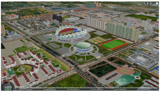
Figure 13.
Large-scale building model rendering.
4.2. Discussion
When compared with the texture composition method [5], our method provides three main advantages: (1) the method generates texture atlases with less storage space in the case where the textures are not compressed; (2) the packed atlas size is controllable, and the multiple textures are packed into one or more texture atlases adaptively depending on the maximum supported texture size of the graphics processing unit card; and (3) the texture-packed building model can be loaded in different 3D visualization software, which is not affected by the 3D graphic API.
The method was designed from the beginning to generate texture atlases adaptively and efficiently. Although the number of geometric vertices increased for texture remapping, it is worth generating 3D building models with adaptive texture atlases for improving the rendering efficiency. As for complex outdoor and indoor building models, the number of geometric vertices increased fast, so both the geometric and texture data should be further considered for model compression.
5. Conclusions and Future Work
This paper presents a size-adaptive texture atlas generation and remapping method for urban building models. The multi-textures are packed into one or more texture atlases adaptively, depending on the maximum supported texture size of the graphics processing unit card. Then, the mesh of the model is reconstructed and mapped according to the original texture type of each triangle. As for the triangle with the original non-tiled texture, new UV coordinates in the texture atlases are calculated, while the triangle with the original tiled texture is clipped into many unit triangles to apply the texture mapping method. Single building models and large-scale urban scenes were tested for their rendering efficiency and effect. The experimental results show that the method could pack all the textures of an urban model without losing accuracy and significantly improve the rendering efficiency of the large-scale urban scene.
This paper provides a solution for users to pack multiple textures and export a textured building model. Since this method achieves texture remapping at the cost of increasing the geometric vertices, it can be further improved. Meanwhile, with the development of KTX texture compression technology [32], the data volume of the 3D building model can be further compressed. In the future, 3D building model compression methods that take into account both the geometric and texture accuracy will be studied for smart city visualization.
Author Contributions
Conceptualization, Xuequan Zhang and Wei Liu; methodology, Xuequan Zhang; software, Xuequan Zhang and Zihe Hu; validation, Zihe Hu; formal analysis, Bing Liu; investigation, Xin Zhao; data curation, Xin Zhao; writing—original draft preparation, Xuequan Zhang; writing—review and editing, Wei Liu; visualization, Xuequan Zhang; supervision, Wei Liu; project administration, Bing Liu; funding acquisition, Xin Zhao. All authors have read and agreed to the published version of the manuscript.
Funding
This research was supported by research funds from the Major State Research Development Program of China (No. 2017YFB0504103) and a smart city research fund from the Huaibei Urban Administration.
Institutional Review Board Statement
Not applicable.
Informed Consent Statement
Not applicable.
Data Availability Statement
The experiment data are not publicly available due to the data privacy policy of the project partners.
Acknowledgments
The authors would like to thank the Huaibei Urban Administration for their initiatives in 3D urban visualization.
Conflicts of Interest
The authors declare no conflict of interest.
References
- Lv, Z.; Li, X.; Wang, W.; Zhang, B.; Hu, J.; Feng, S. Government affairs service platform for smart city. Future Gener. Comput. Syst. 2018, 81, 443–451. [Google Scholar] [CrossRef]
- Zhang, X.; Zhong, M.; Liu, S.; Zheng, L.; Chen, Y. Template-Based 3D Road Modeling for Generating Large-Scale Virtual Road Network Environment. ISPRS Int. J. Geo-Inf. 2019, 8, 364. [Google Scholar] [CrossRef] [Green Version]
- Hu, Z.; Guo, J.; Zhang, X. Three-Dimensional (3D) Parametric Modeling and Organization for Web-Based Visualization of City-Scale Pipe Network. ISPRS Int. J. Geo-Inf. 2020, 9, 623. [Google Scholar] [CrossRef]
- Zhang, L.; Han, C.; Zhang, L.; Zhang, X.; Li, J. Web-based visualization of large 3D urban building models. Int. J. Digit. Earth 2014, 7, 53–67. [Google Scholar] [CrossRef]
- Martinez, J.; Andujar, C. Space-optimized texture atlases for 3d scenes with per-polygon textures. In Proceedings of the 2010 18th Pacific Conference on Computer Graphics and Applications, Hangzhou, China, 25–27 September 2010; pp. 14–23. [Google Scholar]
- Campomanes-Álvarez, B.R.; Cordon, O.; Damas, S. Evolutionary multi-objective optimization for mesh simplification of 3D open models. Integr. Comput. Aided Eng. 2013, 20, 375–390. [Google Scholar] [CrossRef] [Green Version]
- Yi, R.; Liu, Y.-J.; He, Y. Delaunay mesh simplification with differential evolution. ACM Trans. Graph. 2018, 37, 1–12. [Google Scholar] [CrossRef]
- Huang, J.; Wang, X.; Wang, J. Mesh simplification algorithm based on edge curvature metrics and local optimization. Int. J. Modeling Simul. Sci. Comput. 2020, 11, 1950042. [Google Scholar] [CrossRef] [Green Version]
- Li, Q.; Sun, X.; Yang, B.; Jiang, S. Geometric structure simplification of 3D building models. ISPRS J. Photogramm. Remote Sens. 2013, 84, 100–113. [Google Scholar] [CrossRef]
- Xie, J.; Zhang, L.; Li, J.; Wang, H.; Yang, L. Automatic simplification and visualization of 3D urban building models. Int. J. Appl. Earth Obs. Geoinf. 2012, 18, 222–231. [Google Scholar] [CrossRef]
- Li, M.; Nan, L. Feature-preserving 3D mesh simplification for urban buildings. ISPRS J. Photogramm. Remote Sens. 2021, 173, 135–150. [Google Scholar] [CrossRef]
- Google/Draco. Available online: https://github.com/google/draco (accessed on 6 October 2021).
- Campisi, P.; Hatzinakos, D.; Neri, A. A perceptually lossless, model-based, texture compression technique. IEEE Trans. Image Process. 2000, 9, 1325–1336. [Google Scholar] [CrossRef] [PubMed]
- Pagés, R.; Arnaldo, S.; Morán, F.; Berjón, D. Composition of Texture Atlases for 3D Mesh Multi-texturing. In Proceedings of the Eurographics Italian Chapter Conference, Genova, Italy, 18–19 November 2010; pp. 123–128. [Google Scholar]
- Dai, X.; Xiong, H.; Gong, J. A multi-texture automatic merging approach for the 3D city models. Geomat. Inf. Sci. Wuhan Univ. 2015, 40, 347–352. [Google Scholar]
- Wynn, C. Opengl Render-to-Texture; GDC, NVIDIA Corporation: San Jose, CA, USA, 2002. [Google Scholar]
- Dessein, A.; Smith, W.A.; Wilson, R.C.; Hancock, E.R. Seamless texture stitching on a 3D mesh by poisson blending in patches. In Proceedings of the 2014 IEEE International Conference on Image Processing (ICIP), Paris, France, 27–30 October 2014; pp. 2031–2035. [Google Scholar]
- Liang, J.; Gong, J.; Li, W.; Ibrahim, A.N. A visualization-oriented 3D method for efficient computation of urban solar radiation based on 3D–2D surface mapping. Int. J. Geogr. Inf. Sci. 2014, 28, 780–798. [Google Scholar] [CrossRef]
- Kováč, O.; Mihalík, J. Lossless encoding of 3D human head model textures. Acta Electrotech. Et Inform. 2015, 15, 18–23. [Google Scholar] [CrossRef]
- Zhiqiang, D.; Pan, L.; Xiaoling, Z.; Yeting, Z.; Yixuan, Z. Texture Optimization Methodology for 3D Building Based on Super Face. Geomat. Inf. Sci. Wuhan Univ. 2014, 39, 1401–1405. [Google Scholar]
- Lodi, A.; Martello, S.; Monaci, M. Two-dimensional packing problems: A survey. Eur. J. Oper. Res. 2002, 141, 241–252. [Google Scholar] [CrossRef]
- Christensen, H.I.; Khan, A.; Pokutta, S.; Tetali, P. Approximation and online algorithms for multidimensional bin packing: A survey. Comput. Sci. Rev. 2017, 24, 63–79. [Google Scholar] [CrossRef]
- Adamaszek, A.; Wiese, A. A quasi-PTAS for the two-dimensional geometric knapsack problem. In Proceedings of the Twenty-Sixth Annual ACM-SIAM Symposium on Discrete Algorithms, Oregon, USA, 5–7 January 2014; pp. 1491–1505. [Google Scholar]
- Gálvez, W.; Grandoni, F.; Heydrich, S.; Ingala, S.; Khan, A.; Wiese, A. Approximating geometric knapsack via L-packings. In Proceedings of the 2017 IEEE 58th Annual Symposium on Foundations of Computer Science (FOCS), Berkeley, CA, USA, 15–17 October 2017; pp. 260–271. [Google Scholar]
- Gálvez, W.; Grandoni, F.; Khan, A.; Ramírez-Romero, D.; Wiese, A. Improved Approximation Algorithms for 2-Dimensional Knapsack: Packing into Multiple L-Shapes, Spirals, and More. arXiv 2021, arXiv:2103.10406. [Google Scholar]
- Liu, H.; Zhou, J.; Wu, X.; Yuan, P. Optimization algorithm for rectangle packing problem based on varied-factor genetic algorithm and lowest front-line strategy. In Proceedings of the 2014 IEEE Congress on Evolutionary Computation (CEC), Beijing, China, 6–11 July 2014; pp. 352–357. [Google Scholar]
- Dowsland, K.A.; Thompson, J. Simulated annealing. In Handbook of Natural Computing; Springer-Verlag: Berlin/Heidelberg, Germany, 2012; pp. 1623–1655. [Google Scholar]
- Harvey, B.R. Transformation of 3D co-ordinates. Aust. Surv. 1986, 33, 105–125. [Google Scholar] [CrossRef]
- Schulze, T.; Gessler, A.; Kulling, K.; Nadlinger, D.; Klein, J.; Sibly, M.; Gubisch, M. Open Asset Import Library (Assimp). Computer Software. Available online: https://github.com/assimp/assimp (accessed on 6 October 2021).
- 3D Tiles Specification. Available online: https://github.com/CesiumGS/3d-tiles/tree/main/specification (accessed on 6 October 2021).
- Liu, F.; Zhang, H.; Hu, Y.; Guo, X.; Zhu, Z.; Jia, J.; Zhu, H. Cesium Based Lightweight WebBIM Technology for Smart City Visualization Management. In Proceedings of the International Conference on Inforatmion technology in Geo-Engineering, Guimarães, Portugal, 29 September–2 October 2019; pp. 84–95. [Google Scholar]
- Khronos Group Inc. KTX File Format Specification 2.0. Available online: https://github.khronos.org/KTX-Specification/ktxspec_v2.html (accessed on 6 October 2021).
Publisher’s Note: MDPI stays neutral with regard to jurisdictional claims in published maps and institutional affiliations. |
© 2021 by the authors. Licensee MDPI, Basel, Switzerland. This article is an open access article distributed under the terms and conditions of the Creative Commons Attribution (CC BY) license (https://creativecommons.org/licenses/by/4.0/).