Article

Real-Time Co-Editing of Geographic Features

1
Department of Geodesy and Geomatics, University North, Jurja Križanića 31b, 42000 Varaždin, Croatia
2
Geoweb, 44000 Sisak, Croatia
*
Author to whom correspondence should be addressed.
ISPRS Int. J. Geo-Inf. 2024, 13(12), 441; https://doi.org/10.3390/ijgi13120441
Submission received: 25 September 2024 / Revised: 24 November 2024 / Accepted: 3 December 2024 / Published: 7 December 2024

Abstract

:
Real-time GIS enables multiple geographically dislocated users to collaboratively edit geospatial data. However, being based on the strong consistency model, traditional real-time GIS implementations cannot provide fully automatic conflict resolution. In highly dynamic situations with increased probability for conflicts, this will hinder user experience. Conflict-free replicated data types (CRDTs), a technology based on a more relaxed concurrency control model called strong eventual consistency, can resolve all conflicts in real time, letting the users work on their local copies of the data without any restrictions. The application of CRDTs to real-time geospatial geometry co-editing has, to the best of our knowledge, not been investigated. Within this research, we therefore developed a simple web-based real-time geospatial geometry co-editing system using an existing CRDT implementation in Javascript coupled with OpenLayers. When applied to the co-editing of geospatial geometry in its native form, standard CRDT conflict resolution mechanics exhibit some issues. As an attempt to address these issues, we developed an advanced operation generation technique named “tentative operations”. This technique allows for the operations to be generated over the most recent session-wide state of the data, which in effect highly reduces concurrency and provides “geometry aware” conflict resolution. The tests we conducted using the developed system showed that in low-latency network conditions, the negative effects of standard CRDT conflict resolution mechanics do get minimized even under increased system loads.

1. Introduction

Crowdsourcing can be utilized for various purposes, one of which is the collaborative collection and editing of geospatial data by non-professionals, known as Volunteered Geographic Information (VGI) [1]. The advent of VGI started some twenty years ago with the Open Street Map (OSM) initiative. In OSM, data are collected and co-edited using an asynchronous, off-line workflow that ensures the consistency of the data. Conflicts are detected during the upload of the changes to the master OSM database and must be manually resolved before changes are accepted [2]. While appropriate for such a protracted co-editing initiative, this asynchronous approach will not fit cases where the data need to be collected and updated in real time, such as in disaster and emergency response, military conflicts, and similar scenarios.
Real-time online GIS can comply to such requirements by providing the ability for multiple simultaneous users to co-create and co-edit geospatial features in real time. The main challenge in real-time GIS co-editing is how to control concurrency [3], i.e., to manage conflicts that can occur when identical data items are simultaneously updated by different users. The research on concurrency control in the domain of geospatial data co-editing primarily followed traditional database-like approaches [4] adopted to geospatial data, both pessimistic [5,6,7] and optimistic [8,9,10]. An optimistic approach hopes that no conflicts will occur and lets each concurrent user work freely on its own copy of the data. When conflicts do occur, they are typically resolved manually. A pessimistic technique, on the other hand, prevents the occurrence of conflicts in the first place. This is achieved through the locking of various granularities. In all of the described cases, strict consistency can be ensured.
Using traditional approaches does not come without a price, which differs depending on the one used. In optimistic cases, some of the updates might have to be sacrificed and discarded or a manual consensus on how to combine them has to be agreed on by the original editors or arbitrated by a third party. On the positive side, the users can work on their private copies of the data without any restrictions. In pessimistic cases, no conflicts can occur in the first place; however, the responsiveness of the system is typically reduced. Nevertheless, as two recent studies have shown, using advanced technologies such as NoSQL databases [10] or separating public and private workspaces [5] can facilitate the implementation of advanced real-time GIS co-editors.
In the domain of distributed databases, a standard consistency model, called strong consistency, ensures that a set of distributed databases behave as if they were a single database. Enforcing strong consistency can introduce bottlenecks and lags, requiring significant hardware resources and time to implement. In order to overcome the drawbacks introduced by strong consistency and those of traditional concurrency control approaches, in the domain of real time text co-editing a different, more relaxed approach called strong eventual consistency [11,12] has been invented. Strong eventual consistency, unlike strong consistency, lets each site edit its local copy of the data without any restrictions and replicate all the updates to all other sites, which, upon reception, apply them on their local data. Temporary local inconsistencies are allowed between the participating sites, but it is guaranteed that, once all sites have received the same set of updates, they will be in the same state (i.e., they will converge). More precisely, each update generated on each participating site 1. must be guaranteed to execute without any constraints on all other participating sites and 2. must, during execution on remote sites, enforce syntactic consistency. Syntactic consistency, here, refers to the requirement that the intent each operation had on the generating site must be kept on all other sites (e.g., to insert the letter ‘e’ after letter ‘y’ and before letter ‘s’ to form the word ‘yes’ on all sites). Given 1 and 2, when all sites receive all updates, they will be in the same state and that state will reflect the overall cumulative intent of all the operations generated within a session. Since the strong eventual consistency model allows for updates on the local data to be made concurrently, conflicts may occur. However, in order to satisfy requirement 1, all conflicting operations must be executable on all sites, which requires some compromises to be made.
Two prominent methodologies have been devised for achieving strong eventual consistency, particularly in the domain of the real-time co-editing of text: operational transformation (OT) [13] and commutative replicated data types (CRDTs) [14] (later renamed to conflict-free replicated data types). OT, which emerged in the late 1980s, relies on the relative positioning of operations on all participating sites’ local copies of the data, which inherently lacks commutativity. This in turn requires the devising of complex and often error-prone transformation functions [15]. As an alternative, a total order of operations can be established by the means of a central server such as in [16], hence reducing the complexity of transformation functions. The latter approach is used by the most prominent real-time on-line text co-editing system, Google docs. Extensive research has been conducted on the topic of OT over the years [17]. However, to the best of our knowledge, no attempts have been made to investigate its applicability for real-time geospatial data co-editing.
Different to OT, CRDTs, introduced in the mid-2000s, are built upon the monotonicity in a semi-lattice and commutativity [11]. To achieve commutativity, instead of using relative positions as OT does, CRDTs use unique identifiers to correctly position operations. With the advent of CRDTs, the research community lost interest in OT. Therefore, we based this initial research on real-time geospatial feature co-editing on CRDT technology. As is the case with OT, the applicability of CRDTs for rapid real-time geospatial data co-editing has not, to the best of our knowledge, been researched. Besides the studies focusing on using CRDTs for co-editing of text (listed in Section 2.1), recently, CRDTs have been used for the real-time co-editing of solid models using CAD (computer-aided design) [18,19] and for graphic co-editing [20], to name only the domains at least distantly similar to geospatial feature co-editing. The research line from the domain of CAD-based solid modeling considers geometric primitives (e.g., cylinder, box, etc.) coupled with solid modeling operations (e.g., extrude, filet, etc.) and builds conflict detection and resolution mechanisms using the so-called collaborative feature dependence graph (CFDG). Geospatial features are also made out of geometry components (e.g., linear rings as boundaries of a polygon), potentially within a multilevel hierarchical structure (e.g., geometry collections). However, besides the high-level operations on components (e.g., create/destroy component, split geometry, etc.), the lowest-level operations on geospatial features’ geometries consider individual points (insert, delete, move point). We consider that sets of points representing the components of geometries face different challenges in terms of conflict resolution mechanisms. Therefore, within this research, we started from linear geometries defined by ordered sets of points. Nevertheless, the approach with the graph-based representation of operations might prove to be a sound starting point when complete geospatial object geometries and higher-level operations start to be considered.
Since the linear geometry of geospatial features (ordered sets of points) closely resembles text (ordered sets of words/letters), intuitively, it can be anticipated that CRDTs should be applicable to co-edit it. If applicable, introducing CRDTs into the geospatial domain could open a whole new family of real-time geospatial feature co-editing applications. This study, therefore, aimed to investigate the applicability of existing CRDTs to the real-time co-editing of geospatial features’ geometry components. At this time, it disregards the higher levels of the composition or aggregation of geospatial feature geometry and focuses solely on the geometry components, more precisely their atomic building blocks and points. It first focuses on finding and analyzing the specifics of CRDT conflict resolution mechanisms applied to the co-editing of geospatial features’ geometry components. Following, it proposes possible solutions to some issues that those specifics pose, focusing primarily on real-time co-editing scenarios. In terms of performance, it does not aim to find solutions with optimal time complexity or performance but rather the ones that best handle conflict-rich situations while conforming to basic geometry correctness rules.
The rest of this paper is organized as follows. Section 2 introduces CRDT concepts in general, along with a light introduction of their applicability for the co-editing of the geometry of geospatial features. Section 3 then gives an in-depth analysis of some specific concurrency and consistency issues related to geometry co-editing using standard CRDTs. Section 4 is the main part of this work. It describes concepts and algorithms that can be used to minimize concurrency during the rapid real-time co-editing of geographic features, which in turn resolves the issues described in Section 3. Section 5 describes a test implementation of a system based on the concepts and algorithms from Chapter 4 and the results of tests carried out using the implementation. Section 6 presents a discussion on the testing results. Section 7 wraps up the paper up with conclusions and some possible directions for further work.

2. State of the Art

2.1. CRDTs for Ensuring Strong Eventual Consistency

In CRDTs, updates are called operations. Two operations are said to be concurrent if neither was aware of the other at the time of their respective creation. Concurrent CRDT operations on different data items always commute since the positioning of elements to be operated on uses unique identifiers instead of their relative positions as OT does. To make a CRDT fully commutative, concurrent operations on the same data items must also be made commutative. When all operations become commutative, no conflicts can ever occur, hence the name conflict-free replicated data types. A typical example of a conflict is when one operation deletes an item that another concurrent operation updates. CRDTs, in general, use three primary strategies to handle conflicts [21]:
  • Multi-value register (MVR);
  • Last writer wins (LWW);
  • Observed remove (OR).
The MVR strategy retains all versions of conflicting operations, leaving conflict resolution to higher-level application logic. The LWW strategy, on the other hand, prioritizes the latest operation, overwriting all preceding conflicting ones. The OR strategy ensures that additions override deletions unless the deletion operation observed the addition it intends to remove. This means that an operation can remove only the elements that existed at the moment of its creation. Hence, situations where a delete operation executed remotely would remove an element different to the one deleted on the generating site cannot occur.
All three conflict handling strategies ensure the commutativity of operations, but with different consequences and with different levels of complexity of implementation. Both the MVR and LWW strategies are less complex because they either do not attempt to resolve conflicts (MVR) or simply discard an operation when a newer one appears. The OR strategy surpasses both these drawbacks at the cost of more complex concepts and algorithms.
Shapiro et al. [22] introduced a first systematization of CRDTs as the means to replicate content (e.g., letters in a text co-editing system). Two different CRDT algorithm families were invented, one based on fixed-size identifiers and the other on variable-size identifiers.
The fixed-size identifier family members, primarily WOOT [23] and RGA [24], followed by numerous derivates thereof, utilize sequence data structures and never actually delete elements. Instead, delete operations only mark the target element as deleted and retain it in the data structure as a “tombstone”. A tombstone is an element that exists and participates equally in the CRDT data structure (the model) but is not displayed in the user interface (the view). Through the use of tombstones, the OR strategy is effectively implemented since a remote delete operation can only delete an element that exists in the local data structure.
WOOT implements only insert and delete operations. Since delete operations only mark an element as a tombstone using its identifier, two concurrent delete operations on the same element commute; hence, no conflict occurs. A concurrent insert and delete operations also commute since the integration algorithm uses existing elements regardless if they have been deleted (converted into tombstones) or not. The challenge is how to ensure that concurrent inserts commute. In order to ensure the commutativity, two concurrent inserts must be integratable regardless of the order of integration.
In order to consistently integrate each insert operation on all sites, WOOT uses a combination of previous and next element identifiers in combination with the actual element’s identifier. Given their complexity, we do not attempt to explain the details of any CRDT integration algorithms. The interested reader is directed to their respective original papers. However, some basic concepts of another CRDT integration algorithm, similar to WOOT, will be generally explained later in the text.
The drawback of the tombstone approach is that the CRDT data structure grows indefinitely (nothing is ever actually deleted) so the authors in their respective papers reflect on the options to garbage collect tombstones. In practice, instead of implementing complex garbage collection mechanisms, optimization techniques can be used, such as managing larger sets of content items as one [25].
Variable-size identifier family members, such as LOGOOT [26], Treedoc [14], and LSEQ [27], employ tree-based data structures and either do not require tombstones at all or can efficiently garbage collect them. However, their identifiers grow in size with each new operation.
All early implementations of CRDT algorithms were slow and seemed impractical for real-world scenarios [28]. The advent of versatile, fast, and efficient CRDTs [29,30] began with the YATA algorithm [31], which builds upon the concepts of WOOT [23]. In particular, this relates to YATA’s implementation in the JavaScript co-editing framework called YJS [32]. Another competitor in the domain of versatile and fast CRDT frameworks is Automerge [33,34], which builds upon RGA [24] concepts.
Given that the two currently most popular CRDT frameworks, YJS and Automerge, operate on fixed-size identifier concepts, we opted to base our research on these as well, primarily on YATA. Both YJS and Automerge are frameworks providing versatile off-the-shelf functionalities, with their core CRDT integration algorithm implementations deeply interleaved with many aspects of the larger framework. Therefore, extracting or modifying their integration algorithm’s code is not a trivial task. However, there exists a simple and minimal implementation of both the YATA and Automerge integration algorithms’ concepts called Reference CRDTs [35]. In Reference CRDTs, the majority of the code is common to both YJS and Automerge implementations. Moreover, Reference CRDTs include a third, academically unpublished CRDT integration algorithm called Sync9. We decided to use Reference CRDTs as the basis for the test implementation within this research since its versatility opens possibilities for various subsequent experiments.

2.2. Linear Geometry (Co-)Editing Using CRDTs

To enable the seamless synchronization of multiple remote instances of an application (sites) participating in a co-editing session, CRDT frameworks maintain their own, internal data structure on each of the sites. The data that an application wants to replicate using a CRDT framework have to be encoded and stored in such a CRDT data structure. The application itself can then either be built directly on top of the CRDT data structure, or the CRDT data structure can be used to synchronize some application-specific data structure. In this particular case, we employed the latter approach and built our application using the Javascript web mapping library OpenLayers [36].
A geospatial feature is an object with several types of attributes, one of which is spatial. Spatial attributes of geospatial features can hold geometric objects of dimensions ranging from 0 to 3. Geometries of dimensions larger than one are composed of an arbitrary number of surfaces bound by closed curves, which in turn are defined by interpolating ordered sets of control points. Usually, the interpolation of the curves is linear, producing a special case of curves, line strings. A possible specialization of line strings, with identical start and end points, are linear rings. Linear rings are used to represent boundaries of surfaces. One of the common requirements for geospatial geometries, in general, is that they must be simple. For line strings, this leads to a requirement that no two line segments making the line string shall intersect [37] (i.e., there shall be no self-intersections).
In this research, we focused on the co-editing of a single such linear geometry. More specifically, we focused on its lowest-most point level. We focused on resolving conflicts automatically (requiring no user action) and in such a manner that line strings being co-edited always remained simple (self-intersection free). The conflict resolution mechanism also needs to ensure that no user action is ever lost.
One-dimensional geometries, such as line strings and linear rings, are typically encoded as sequences (lists, arrays) of points [37] (Figure 1). For the purpose of storing and managing points of a line string, a CRDT data structure is an ordered set of CRDT elements. The physical ordering of CRDT elements is often implemented using linked lists, such as in [19,24,31], but can also be carried out using simple arrays, such as in Reference CRDTs [35]. Further, different approaches use various auxiliary data structures such as hash tables [19] or balanced trees [31] to improve the time complexity (i.e., performance) of the devised algorithms. These, however, are irrelevant low-level implementation details and will not be considered further.
Besides the data structure, a CRDT framework is defined by its order function. The order function ensures a total order of elements on all sites. Through providing for a total order, once all sites receive the identical set of operations, they converge to an identical state. In the case of the fixed-identifier CRDT family, through providing that each element is ordered after its previous element, first, a partial order of operations with identical previous elements is achieved. Then, since all elements have a previous element (with the special case of the first element in the data structure), a total order is achieved. Besides the convergence requirement, each operation’s intent must be preserved. This means that it is not sufficient to only consistently order all elements with an identical previous element but this ordering must preserve the intent that the operation had on its original site. The preservation of intent aspect of the order function is handled differently by the two most prominent members of the fixed-identifier family, YATA (which follows from WOOT) and Automerge (which builds upon RGA). This is briefly described in the last part of this section. The reader interested in a more formal definition and the proofs of transitivity, antisymmetry, and totality for, e.g., YATA, is directed to the original paper [31].
Each CRDT element carries three fundamental types of data: its unique identifier, its integration parameters, and the actual application-specific content. In text co-editing applications, the content of each CRDT element is typically a letter of a text document. In a geometry co-editing application, the specific content will be the geometry. In this research, the application-specific content of a CRDT element is a point of a linear geometry, more precisely coordinates of that point.
A CRDT data structure is modified by executing operations. Typically, the two types of operations used are adding a new element to the data structure (usually referred to as inserting or integrating) and deleting an element from the data structure.
New CRDT data elements are generated upon the edits carried out by users using the application’s GUI (graphical user interface). A simplified procedure is as follows. Upon carrying out an edit using the GUI, generate a new CRDT element, insert it into the local CRDT data structure, and transmit it to all other sites to integrate into their local data structures. Fundamentally, fixed-size identifier CRDTs use the previous element identifier (here specifically referred to as originLeft) as the primary integration parameter.
The three fundamental geometry edit operations on linear geometries are the following: insert point (i.e., split a line segment with a point), move point, and delete point. Suppose that there exists a geometry-editing GUI implemented using some mapping library such as OpenLayers. Edits carried out by users using the GUI are applied to the library’s internal data structure but can also be programmatically converted and encoded in a form appropriate for use with some strong eventual consistency framework, such as a CRDT (Figure 2).
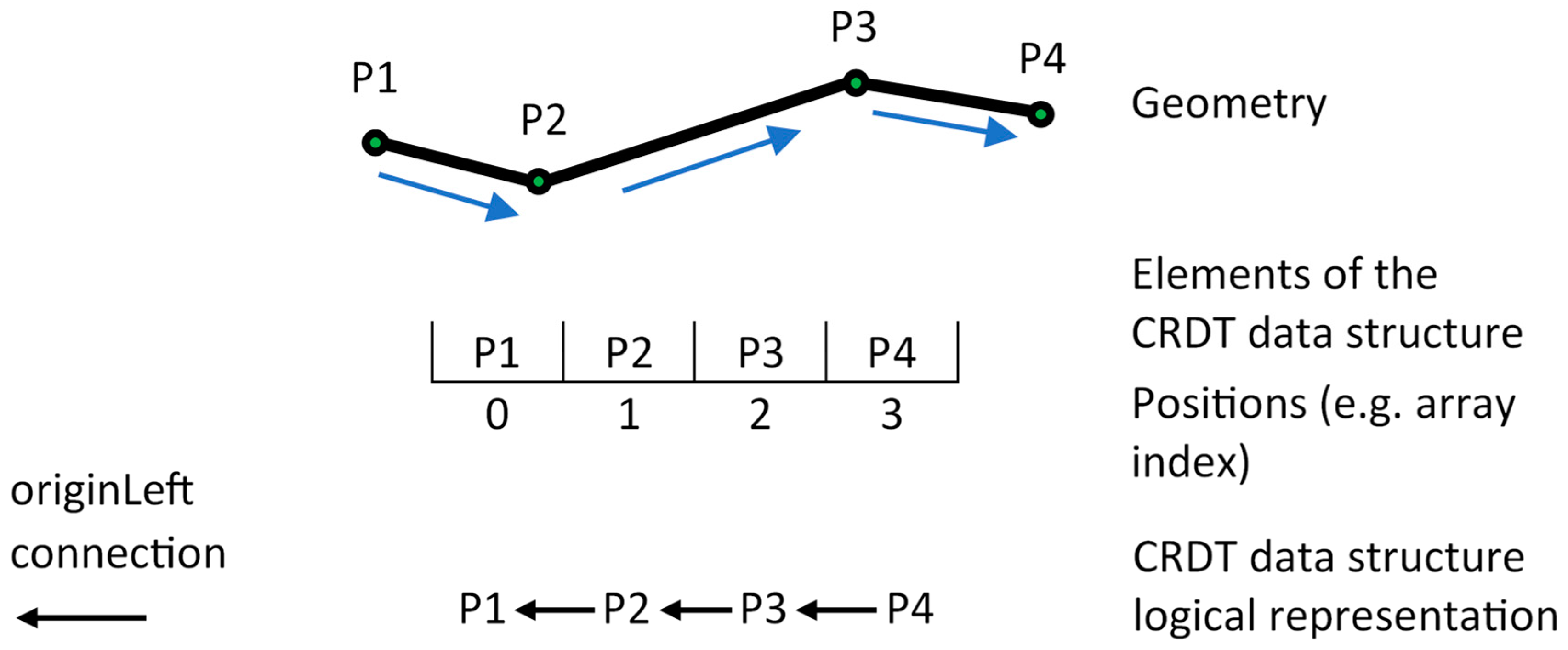
We now introduce a simplified graphical notation to visualize the geometry, the elements of the CRDT data structure in the encoding sense (sequence of points), and in the logical sense with originLeft connections depicted by black arrows (Figure 3).
Recall that fixed-identifier-based CRDTs never actually delete elements but only mark them as deleted, i.e., convert them to tombstones. Following this, the CRDT data structure can be observed in two ways. The CRDT data structure model is an ordered set of all CRDT elements. The CRDT data structure view is an ordered set of non-deleted elements.
To familiarize the reader with concepts of the CRDT data structure model, view, tombstones, and originLeft connections, we provide a visualization (Figure 4) of the two examples from Figure 2, using the graphical notation from Figure 3. Notice how the updated geometry editing library’s data structure (Figure 2) and the CRDT data structure view (Figure 4) correspond. Further, notice that the positions of some elements in the CRDT model and CRDT view differ, following the fact that in the view, the tombstones (in red) are not present.
We first briefly address how CRDT elements are generated. Recall that the position of an element in the CRDT data structure view is identical to its position in the geometry library’s data structure. In fact, the two must be synchronized when operations are generated. Following this requirement and since the edits carried out using the GUI are positioned in the geometry library’s data structure, the position for the new element in the CRDT data structure view is also known. However, the element’s physical position within the data structure is defined by the model. Hence, to determine the element’s real position, the current view must be mapped to the current model. Mapping a position from the CRDT view to CRDT model is straightforward and can be carried out by counting the tombstones to the left of its designated position in the view. Once the new element’s position in the model is determined, its originLeft is the first previous (left) neighbor of the position where the new element is to be inserted in the model. OriginLeft is the primary integration parameter for all the members of the fixed-size identifier family of CRDTs.
Integration algorithms are physical implementations of order functions and are more complex. We only briefly address the concepts needed for understanding the subsequent discussions in this paper. When integrating a new element into the CRDT data structure, the position of the new element’s left neighbor (originLeft) is first found by its identifier. If no other elements of the CRDT data structure are already connected to that element, then the new element is simply inserted in the first position to its right. Both YATA and Automerge use this same primary technique.
If there are elements already connected to the found originLeft element, different approaches are used. Automerge uses a simple counter that globally (session-wide) increases whenever a new element is integrated [34]. All elements with identical originLefts are ordered by the value of this counter. YATA is more sophisticated. Instead of a simple, globally increasing counter, YATA [31] uses another connection, the one to the element positioned to the right of originLeft. During integration, YATA uses this connection as a limit while determining the position to integrate. Another requirement in YATA is that origin connections (connections to originLeft) of elements do not cross.
In both YATA and Automerge, concurrent insertions from different sites cannot be integrated consistently using the mechanics described so far. To overcome this, both use a simple but arbitrary technique. Since each site has its unique ID, then such conflicting insertions can consistently be (and are) ordered using their respective site ID. The ordering can be carried out in either ascending or descending order.
In both implementations, the delete operation is different from insert and trivial. The delete operation only needs to find the target element to be deleted by its identifier and set a flag marking it deleted.

3. Employing CRDTs for Geometry Co-Editing

3.1. Geometry-Based Ordering of Conflicting Inserts

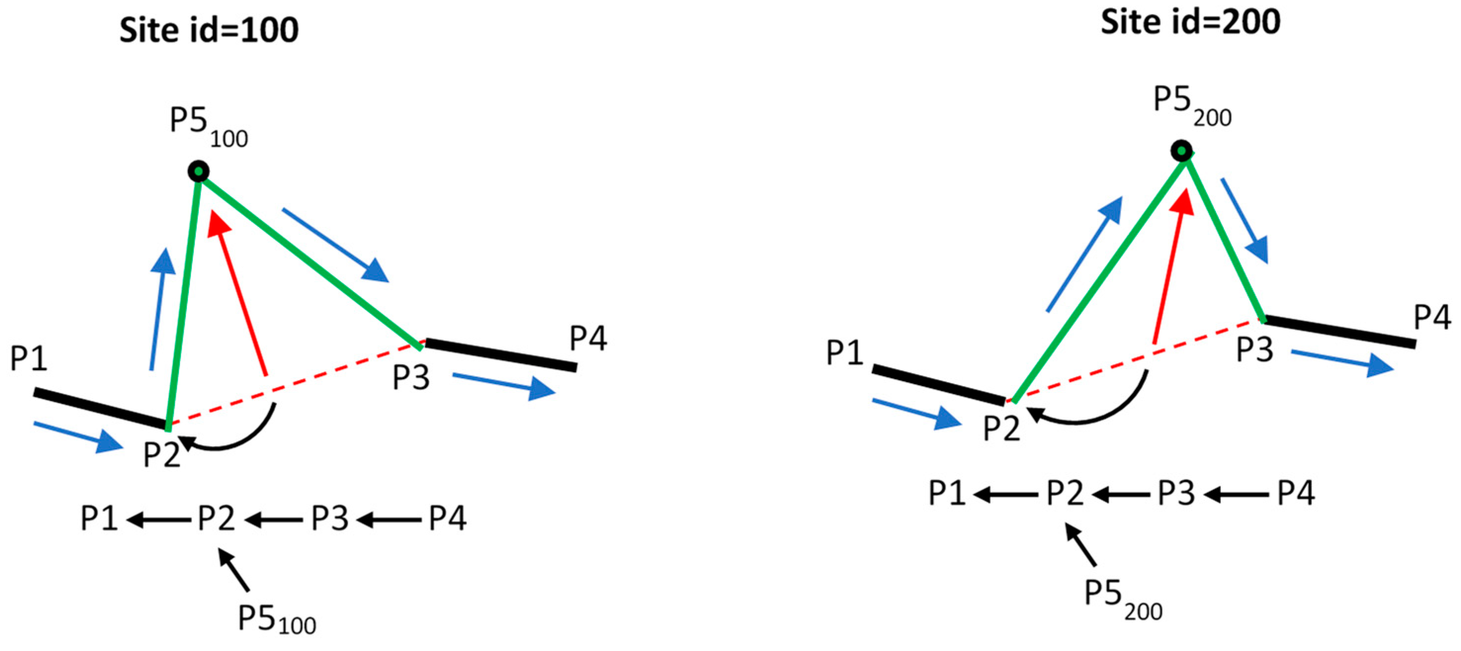
When multiple users co-edit the same geometry using the described CRDT data structure, insertion conflicts will inevitably occur and will be resolved through arbitrary site ID-based ordering. Consider a scenario where two users (User A on site ID = 100 and user B on site ID = 200) concurrently insert a new point with different coordinates (Figure 5). Each site then transmits its created operation to the other.
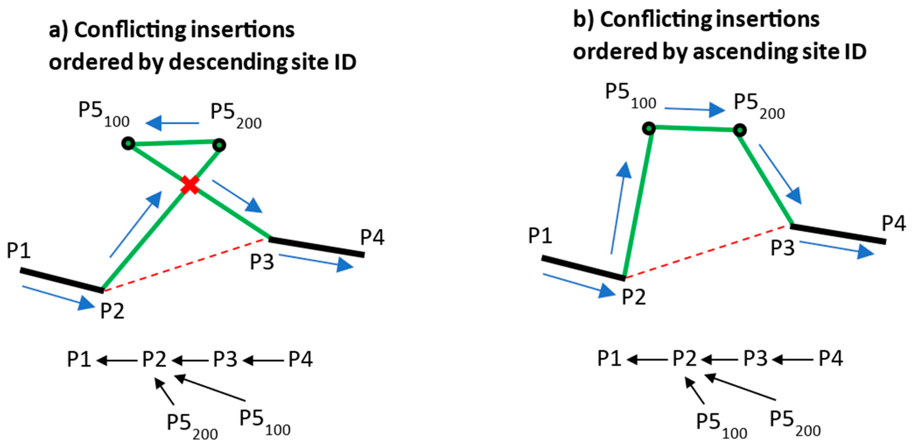
Upon receiving the other site’s operation, both sites find their local element already connected to P2 so they both order the other site’s element by site ID. An arbitrary choice of either ascending or descending ordering can be used for this purpose, based on the application design. Although this ensures the primary goal (convergence on all sites), obviously, ordering by site ID can result in geometrically incorrect orderings (Figure 6) in an unpredictable fashion.
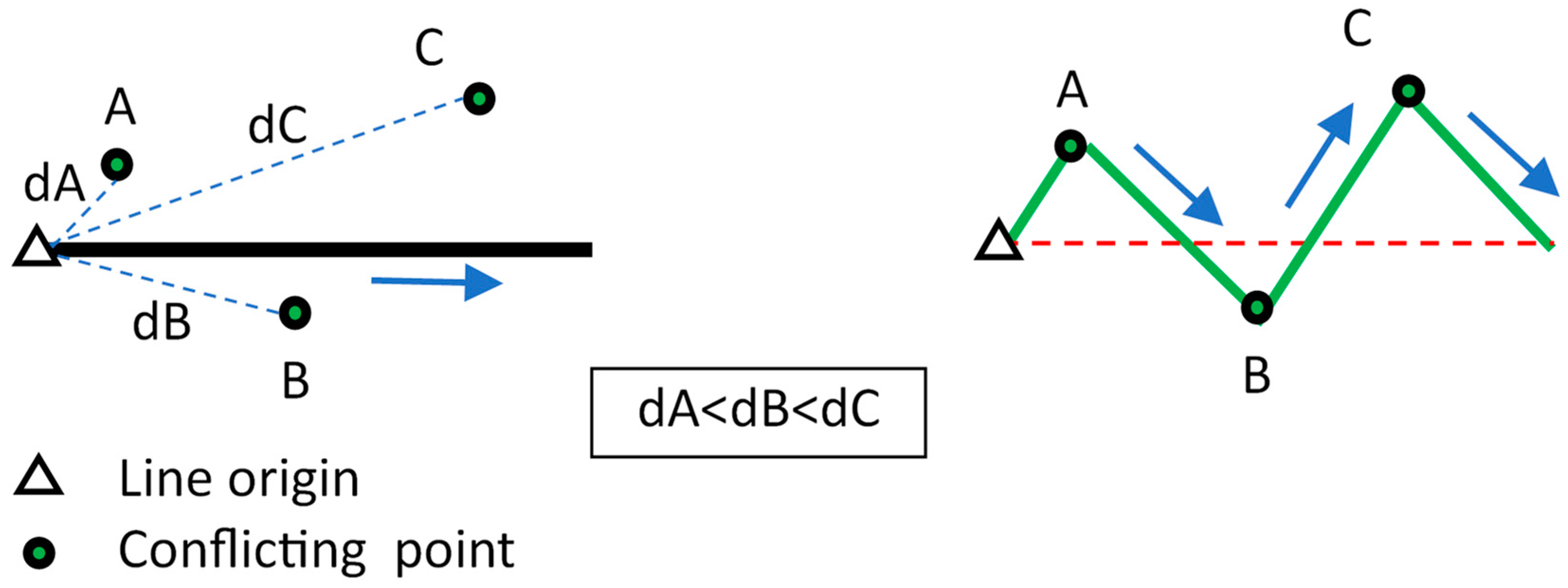
This can be partially addressed. Conflicting inserts always share the same originLeft. Therefore, instead of site ID, a different, globally consistent measure can be used—the distance of the conflicting point from its originLeft point. With this new measure, the CRDT integration mechanics are modified to order conflicting elements based on their geometry instead of using the arbitrary site ID (Figure 7).
Ordering by distance from the origin is obviously superior to simple site-ID based ordering. However, there still exist configurations that can produce geometrically incorrect outputs such as the one depicted in Figure 8.
Besides the limitation described above, ordering by distance from originLeft has another limitation. When two conflicting elements have a tombstone as originLeft, the distances to the origin used to order them will be calculated from a point that does not exist in the actual geometry. Obviously, this can also cause geometrically incorrect orderings.

3.2. Interleaving and the Effects of Editing Direction

Interleaving is the situation when multiple sequential insertions from one site are mixed with concurrent insertions from other sites [38,39]. In text co-editing, interleaving is an unwanted effect resulting in letters from different words being mixed together. The desirable outcome would be to keep the sequentially inserted items together. Modern CRDTs exhibit interleaving depending on the direction of the sequence of inserts. For instance, YJS prevents interleaving when sequential inserts are carried out in a forward direction but allows it when carried out backwards.
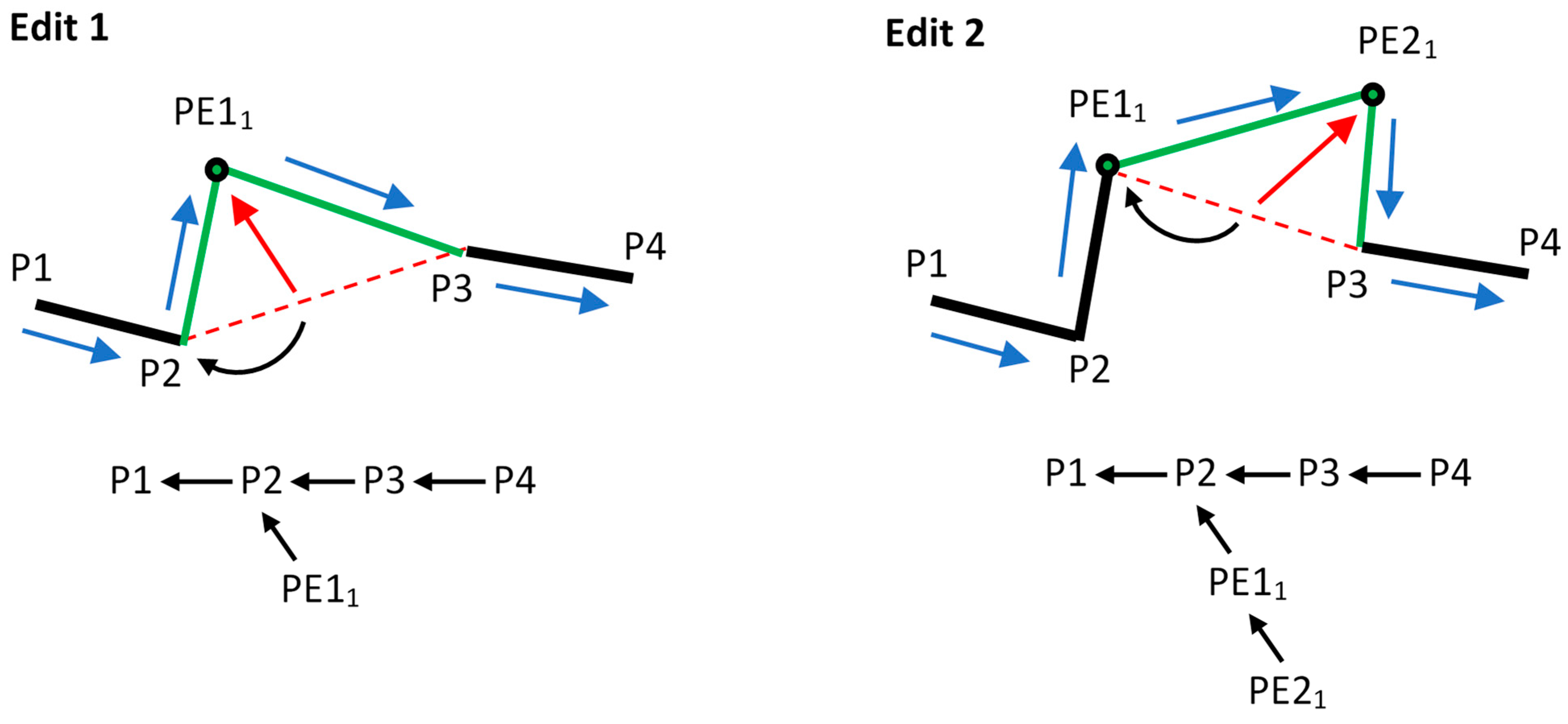
On the contrary, in linear geometry editing, concurrent operations should be able to be interleaved. Correct interleaving would allow for conflicting insertions to result in correct linear geometry. Whether or not interleaving occurs depends strongly on the CRDT data structure concept. The following demonstration uses a YATA-style integration algorithm that relies on originRight to correctly position elements with identical originLeft. Consider the effects on the CRDT data structure of two sequential point inserts carried out in the forward direction on Site 1 (the direction that the data items are created is identical to their ordering in the CRDT data structure) (Figure 9).
The first inserted element has one of the initial elements as originLeft, while the second inserted item has the first inserted element as its originLeft. The two new elements create a two-level hierarchy.
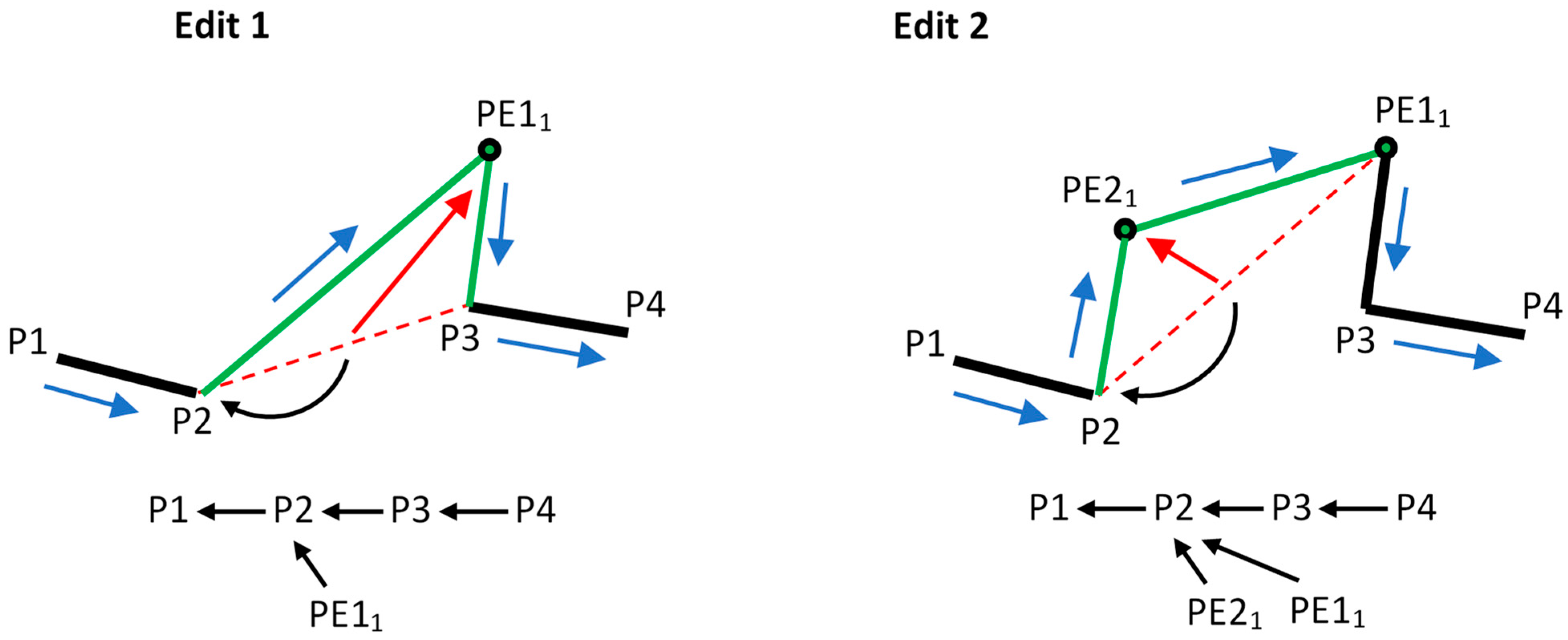
Now, consider the same two point inserts carried out in the backward direction. The two inserted elements are on the same hierarchy level, both connected to the same initial element and with PE21 correctly inserted before PE11 by the means of its originRight connection (Figure 10).
Thus, although the final outcome in the geometry sense (CRDT view) is identical, the logical organization of items in the data structure differs.
Now consider a second site (Site 2) creating a point geometrically between the same two initial points (P2 and P3) as depicted in Figure 11.
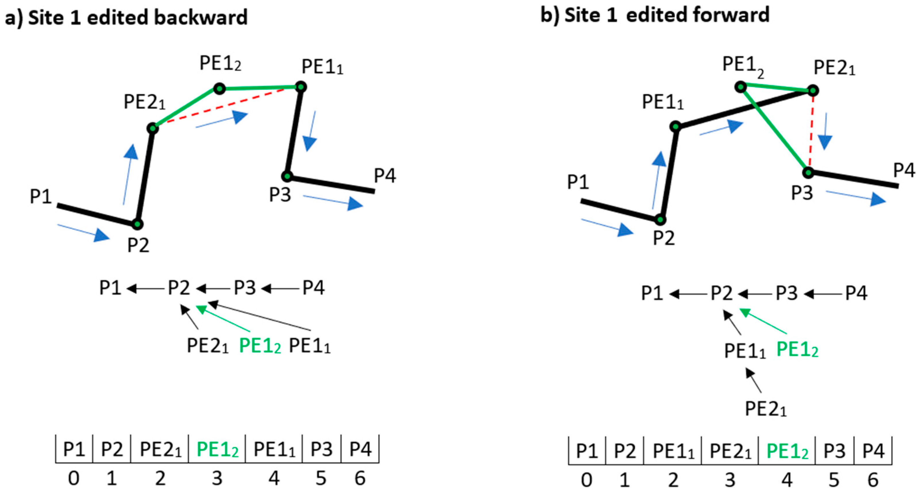
When Site 1 receives Site 2’s operation, if Site 1’s operations were created backward, then Site 1’s element PE21 conflicts with site 2’s PE12 (Figure 12a). As shown earlier, conflicting items can be ordered geometrically. Since PE21 is closer to P2 than PE12, ordering them by distance from origin places PE12 correctly after PE21. Further, since PE12 is also in conflict with PE11 but is closer to P2, it is ordered before PE11.
Conversely, if Site 1’s elements were created forward (Figure 12b), then Site 1’s element PE11 conflicts with Site 2’s PE12 and can, given ordering by distance, be correctly placed first. However, since PE21 has PE11 as originLeft and PE12 has P2 as originLeft, PE21 must, given YATA’s no-origin-crossing rule [31], be ordered before PE12. This results in a geometrically incorrect output.
Since Automerge works based on primary concept identical to those of YATA, Automerge exhibits similar interleaving behavior [38]. In summary, a conflicting point can be correctly interleaved into a sequence of backward-inserted points but not into a sequence of forward-inserted points.

4. Tentative Operations

In highly dynamic co-editing environments that involve numerous participants, a significant number of operations are generated and exchanged within a short period of time. To minimize concurrency, thus avoiding conflicts and their negative effects, it is critical that operations are generated based on the most recent session-wide state of the data. This highlights the importance of the method of generating operations.
The generation of an operation initiates when a user selects an existing geometry element to edit and starts modifying it (e.g., a line segment to be split with a new point or a point to be moved to a new location). The integration parameters for the new CRDT element (e.g., originLeft and originRight in the case of YATA) are determined at that moment. However, since the user has not yet completed the edit, the CRDT element’s content (coordinates) is not yet known. The editing process is complete when the user releases the selected geometry element at a desired location. At that moment, the coordinates for the CRDT element are determined so it can be finalized and integrated. During the period between the initiation and the completion of the edit, the user dynamically modifies the selected geometry element. This process is referred to as dragging.
During the dragging phase, concurrent remote operations may arrive at the user’s site, some of which also being directly in conflict with the local operation. Managing the local and the remote operations can be carried out in two ways. First, it can simply be left to the standard CRDT conflict resolution mechanisms to handle conflicting operations, as described in the previous section. Conversely, if the effects of these remote operations are to be included into the local element’s integration parameters to remove concurrency, then for each conflicting remote operation, a resynchronization of the CRDT data structure view and geometry library’s data structure would need to be carried out and the geometry would be redrawn on the GUI. This in effect means that for each conflicting remote operation, restarting the already initiated local edit would be needed. While both of the approaches are correct, neither is both user friendly and optimized for geometric correctness.
An alternative, conceptually different approach also exists. During dragging, all the received remote operations can be buffered, to be processed when the user completes their edit. While these buffered remote operations cannot be modified, the local operation remains tentative and visible only to the local client until the user completes the edit. Therefore, the initially determined integration parameters of the local operation can be modified before it is finalized, integrated locally and broadcasted to other sites.
The core ideas of this approach are to determine the tentative operation’s integration parameters based on the current local state of the data before integrating the buffered operations, to integrate the buffered operations (producing a more current session-wide state of the data locally), and then to modify the tentative operation’s integration parameters in order to fulfill the following:
  • Preserve the original intent of the operation.
  • Create a session-wide syntactically correct operation.
  • Create the most probable session-wide semantically correct operation.
In terms of the operation’s original intent, the goal is to insert the point at a position that corresponds to its original position. To achieve this, we introduce the concept of the operation’s geometry range and its projection onto the new state of the geometry. Syntactically, the goal is to generate a non-self-intersecting geometric configuration. Since multiple configurations can fulfill the syntactical aspect, the semantical aspect aims to produce the straightest possible geometric configuration.

4.1. Approach

The system generates a tentative operation on a data state that does not include buffered remote operations. After the remote operations are integrated, a relevant part of the local data may change, which could result in a geometrically incorrect output if the tentative operation’s parameters remain unchanged. To ensure that the tentative operation is integrated geometrically correctly, its integration parameters are modified to compensate for the changes introduced by integrating the buffered remote operations.
The concept of a tentative operation’s geometry range is used to enable the preservation of its intent. The original geometry range of a tentative operation is a part of the geometry that it originally intends to modify, as determined at the moment of the operation’s initial creation. After the buffered operations are integrated, the tentative operation must still be integrated within its geometry range to respect its original intent. If the tentative operation’s original geometry range has been modified by integrating buffered remote operations, it must be adjusted to the new state of the data. Conceptually, the approach includes the following steps:
  • When the user initiates dragging, detect and store the geometry range for the tentative operation.
  • When the user completes the edit, integrate all buffered remote operations.
  • If the tentative operation’s geometry range has changed due to the integration of buffered remote operations, adjust the original geometry range to the updated state of the data.
  • Determine the final integration parameters by selecting the most geometrically appropriate position within the adjusted geometry range.

4.2. Tentative Operation’s Geometry Range

We start off by defining the structure of elements and a set of operation types. The geometry of a feature is represented by a set of CRDT elements that form a CRDT data structure. A CRDT element is defined by its integration parameters, a globally unique identifier (ID), and a status attribute (“deleted” or “non-deleted”). Each element contains content in the form of point coordinates. Following the CRDT implementation used, an element is an object defined as follows:
  • element (element.content, element.id, element.originLeft, element.originRight, element.isDeleted).
Two standard types of operations exist: insert element INS (element) and delete element DEL (element). Both operation types take elements as parameters. The INS operation uses the element’s integration parameters to insert it into the CRDT data structure, while the DEL operation uses the element’s identifier (element.id) to find the existing element in the data structure and sets its “isDeleted” attribute to TRUE.
Since the framework we used does not provide a native update operation, we implemented it by creating a two-component operation, combining an insert and a delete. The update operation (UPD) takes two elements as arguments, the element to be inserted and the element to be deleted:
  • UPD (insElement, delElement).
With this basic framework established, we define the concept of the geometry range of a tentative operation. The geometry range of a tentative operation Top, denoted as RTop, consists of the set of line segments over which the operation will be integrated. RTop is defined by its two endpoints, referred to as the left range end (LRE) and right range end (RRE).
  • RTop = (LRE, RRE).
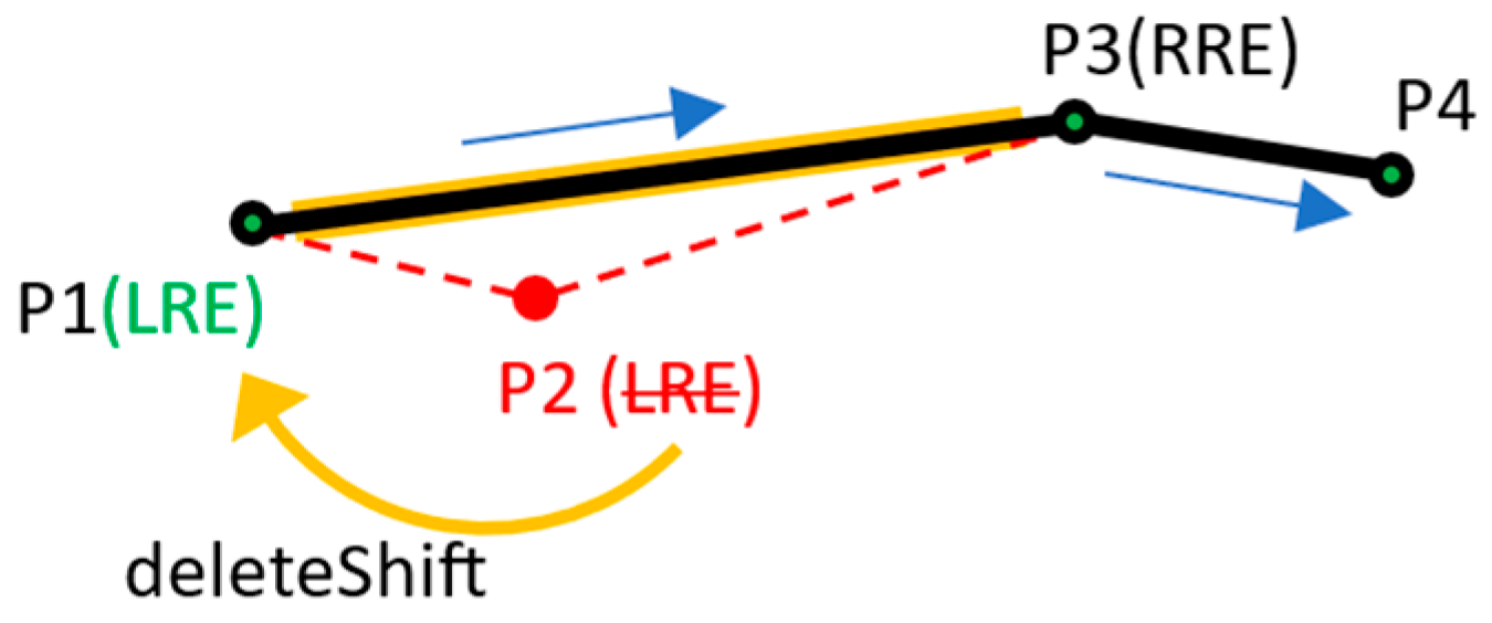
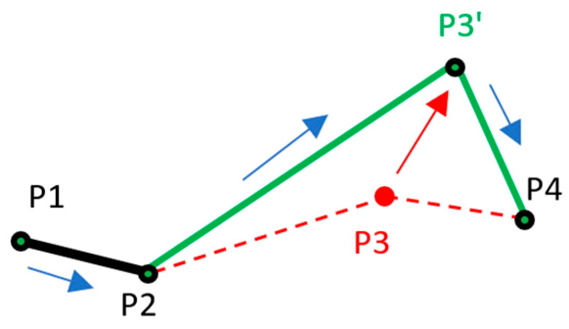
RTop consists of a set of line segments generated by sequentially traversing from LRE to RRE. Initial RTop is generated when Top is generated. Note that line segments are only formed by non-tombstone CRDT elements. Being focused on geometry rather than on CRDT data structure, in the following elaboration, we often refer to non-tombstone CRDT elements as points. For tentative INS operations, initial RTop always consists of a single line segment. This line segment is defined by RRE as the point to be shifted to the right by the insertion (point P3 is RRE on Figure 13a) and LRE, which is the point currently to the left of RRE (point P2 is LRE on Figure 13a). In the CRDT data structure’s logical sense, RRE corresponds to the element currently occupying the position where the new element will be inserted, and LRE is the first non-deleted element to the left of RRE.
For tentative UPDs, RTop always consists of two line segments. The common point between these two line segments is the point to be deleted by the delete component of the UPD (point P2 is the common point in Figure 13b). The other two points that define these two line segments are RRE as the first next (right) point to the common point (point P3 is RRE on Figure 13b) and LRE as the first previous (left) point to the common point (point P1 is LRE in Figure 13b). In the CRDT data structure’s logical sense, RRE is the first undeleted element to the right from the element to be deleted by the operation. LRE is the first non-deleted element to the left of the element to be deleted by the operation.
Local DEL operations do not require handling by the tentative operation mechanism since they operate on uniquely and immutably identified elements.
When integrating remote operations’ elements into the local CRDT data structure, Top’s RTop may change. These changes, known as range end shifts, occur due to the integration of remote DELs and UPDs. Two types of range end shifts on RTop are the following:
  • RTop.deleteShift (Rtop.RRE|RTop.LRE);
  • RTop.updateShift (Rtop.RRE|RTop.LRE).
The deleteShift method shifts RTop’s range ends when remote DEL operations delete them. Consider, for example, starting from the situation in Figure 13a, where Site S0 is in the dragging phase, and that a remote operation DEL(P2), generated by some other site, arrived on S0. When the user completes their edit, S0 starts generating Top’s CRDT element. It first integrates all the buffered remote operations, so after integrating DEL(P2), point P2 will no longer exist (the CRDT element holding P2 is not included in the CRDT view and no longer relevant). Since we want to generate Top’s final CRDT element over the geometrically most current state of the data, RTop must consist of the new line segment generated by executing a remote DEL operation (Figure 14). Hence, through executing deleteShift on RTop’s LRE, it will be shifted from its current point (which is P2) to point P1.
Through executing RTop’s deleteShift method for each remote DEL operation (Op.isDelete) that deleted either of RTop’s range ends, RTop is expanded in its respective direction. More precisely, a deleteShift on LRE moves it from its current point to the next point to its left. A deleteShift on RRE moves it from its current point to the next point to its right.
The updateShift method shifts RTop’s range ends when remote UPDs update them. Consider now that a remote site other than S0 generated and broadcasted the operation UPD(P3’, P3) (Figure 15).
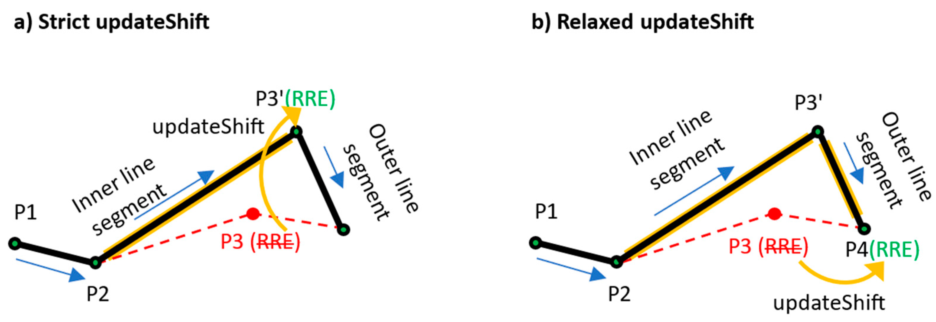
Then, starting again from the situation shown in Figure 13a, where Site S0 is in the dragging phase, consider that this remote UPD(P3’,P3) arrived on S0. When the user completes their edit and S0 starts generating Top by first integrating the buffered remote operations, after integrating UPD(P3’,P3), the new situation on S0 includes the two updated line segments generated by moving point P3 to P3’. One of these two updated line segments is a new version of the original RTop’s line segment (inner line segment). The other of the two updated line segments is the new version of the first next line segment outside of the original RTop (outer line segment). A strict updateShift implementation would only include the new version of the inner line segment into the updated RTop by shifting RRE to P3’ (Figure 16a). However, a more flexible (relaxed) updateShift implementation could also include the new version of the outer line segment into the updated RTop (Figure 16b).
The reasoning behind also devising the relaxed updateShift is based on the following. First, including it into the updated RTop is justified since the immediate neighborhood of RTop (the outer line segment) has also been changed concurrently. Second, by including it, more flexibility will be provided for the final positioning algorithm, as will be demonstrated later. Contrary to this, since deleteShift by definition includes the full effect of the concurrent remote operation to local data (by shifting the affected range end to the outer boundary of the overall geometric change), only the strict implementation is needed.
Each remote UPD (Op.isUpdate) that updated either of Rtop’s range ends will cause a range end shift by executing the updateShift method. Executing relaxed updateShift on LRE moves it from its current point to the first point to the left from the point inserted by this remote UPD. Executing updateShift on RRE moves it from its current point to the first point to the right from the point inserted by this remote UPD. Strict updateShift would simply move the affected range end from its current point to the point inserted by the subject remote UPD.
Recall that both UPD and DEL operations include deletions. Deletions are the actual cause for range end shifts. Conversely to DEL and UPD, and since they do not include any deleting, remote INS operations do not cause range end shifts.
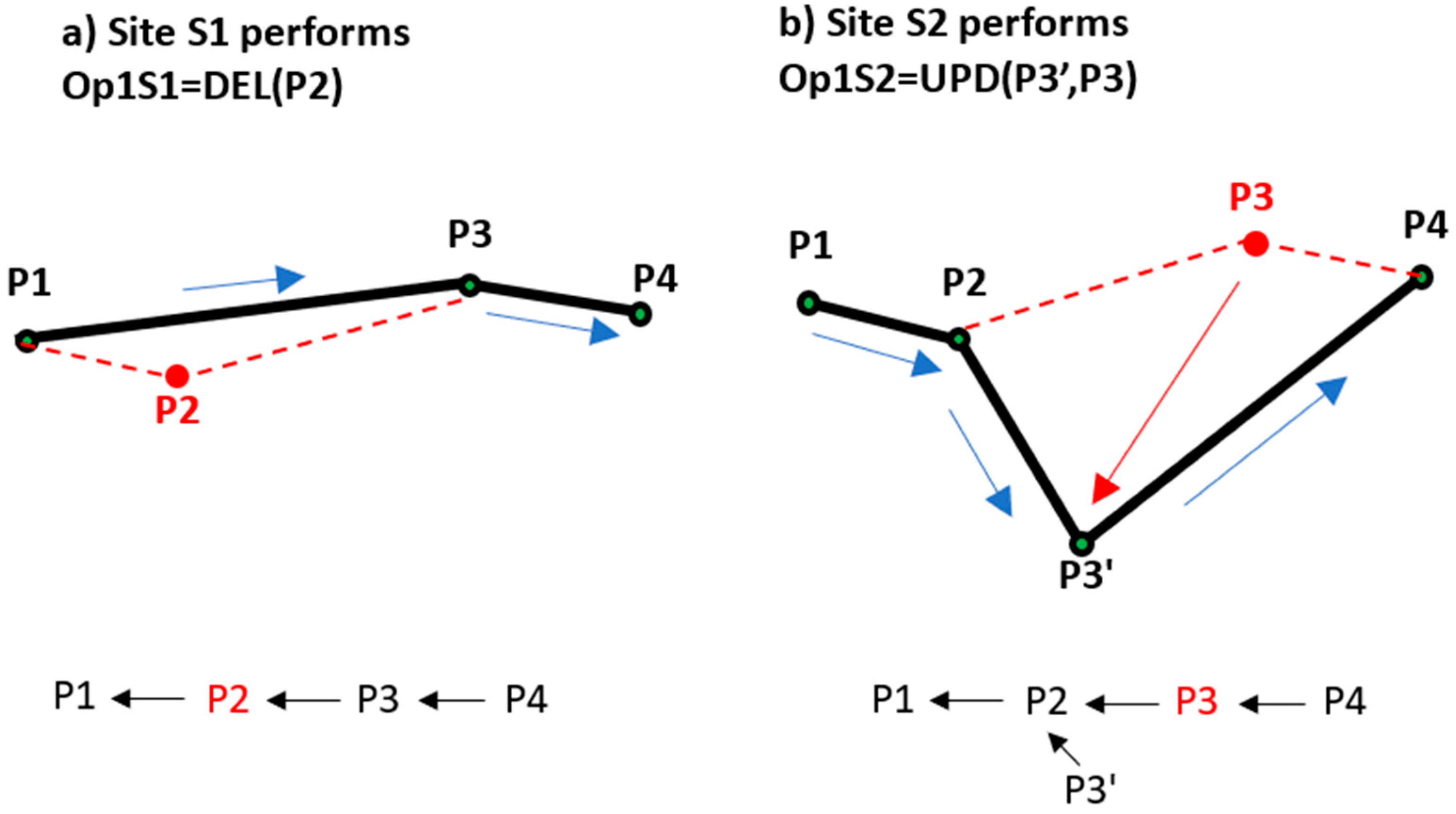
The process of shifting the geometry range ends of a tentative operation is referred to as projecting. We now demonstrate projecting using an example. Consider that a user on Site S0 started their edit and is dragging (as depicted on Figure 13a). The system on S0 generated both the Top and its RTop and waits for the user to complete their edit. Consider also that another two sites, S1 and S2, carry out two edits while S0 is still in dragging mode. First, Site S1 deletes P2 (Op1S1 = DEL(P2)), while Site S2 moves P3 to P3’ (Op1S2 = UPD(P3’, P3)) (Figure 17).
After Sites S1 and S2 integrate each other’s operation, they both end up with the identical situation depicted in Figure 18.
At this moment, Site S0 still holds its tentative operation Top with the associated range RTop. When S0 is integrating Op1S1 and Op1S2, it will check and see that they both operate on RTop’s range ends. Op1S1 deletes RTop’s LRE, and Op1S2 updates its RRE, so site S0 will need to perform the following:
  • RTop.deleteShift(P2) >> RTop = (P1, P3);
  • RTop.updateShift(P3) >> RTop = (P1, P4).
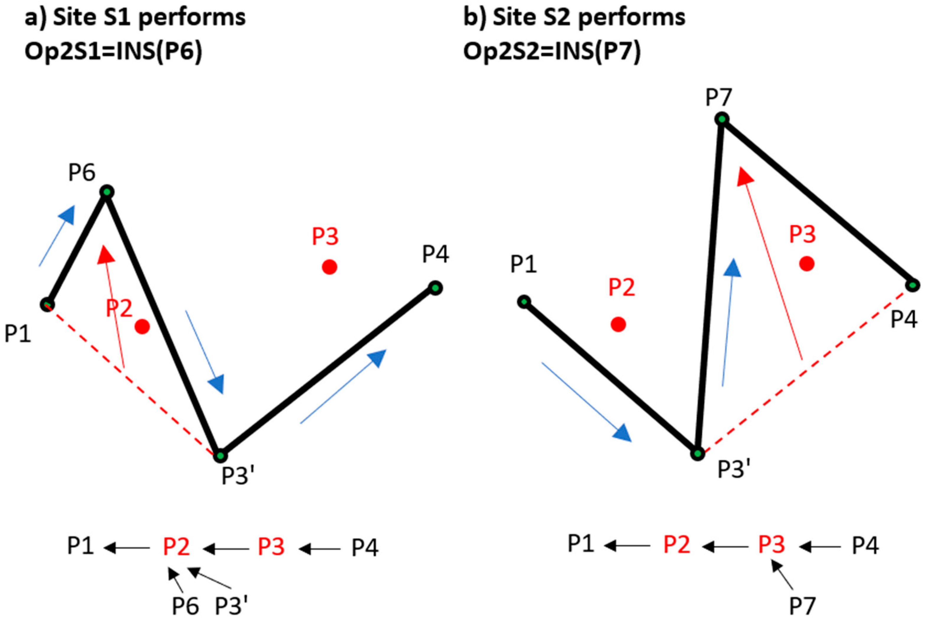
Notice how the flexible updateShift moved RRE to P4 instead of keeping it on P3’. Consider now that Site S1 and Site S2, starting from the state shown in Figure 18, both carry out another edit each, inserting points P6 and P7, respectively (Figure 19).
On Site S1, since in CRDT view P6 must push P3’ to the right, it obtains P3’ as its originRight and tombstone P2 as its originLeft. On Site S2, since in CRDT view P7 must push P4 to the right, it obtains P4 as its originRight and tombstone P3 as originLeft. The final state on both Site S1 and Site S2 after they exchanged and integrated each other’s operations is shown in Figure 20.
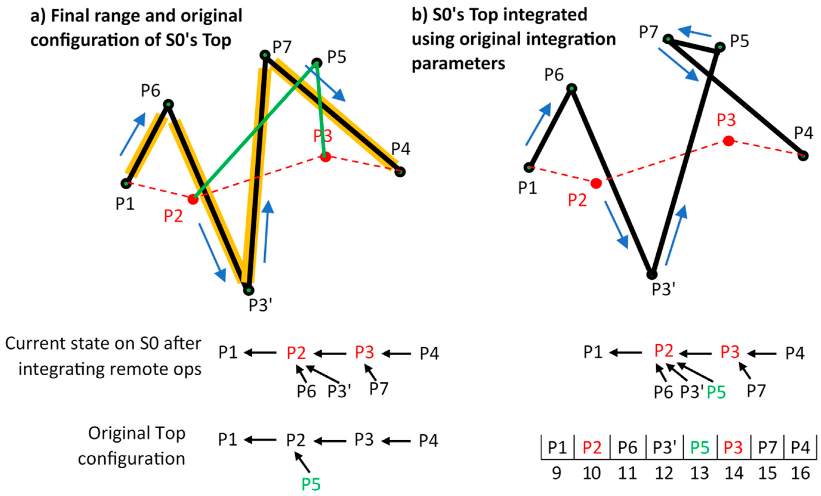
Since Op2S1 and Op2S2 are simple inserts, Site S0 will not need to carry out anything on the range ends of Top when it integrates them. The range of Top will keep its existing definition, RTop = (P1, P4). When its user finishes dragging, Site S0 starts completing its Top by first integrating all the buffered remote operations (Op1S1, Op1S2 Op2S1, Op2S2) into its data structure and simultaneously executing the previously described range end shifts. On Site S0, this results with the Top’s final projected range RTop = (P1, P4) shown in orange in Figure 21a (including also the original configuration of Top = INS(P5) superimposed on top).
In a straightforward implementation (disregarding the effects of remote updates carried out within RTop), Site S0 would then generate its new CRDT element with the originLeft parameter set to P2. Then, if distance-based ordering was used, the final configuration would be as shown in Figure 21b. Since all three have P2 as originLeft, point P5 is inserted after both P6 and P3’ based on it being the furthest from P2.
This example demonstrates how using the operation’s original, uncorrected integration parameters can lead to a geometrically incorrect configurations if its geometry range was modified by conflicting remote operations. Further, it demonstrates how only remote update and delete operations can modify the tentative operation’s geometry range ends. The effects of remote operations of any type on elements within the geometry range will be taken into account by the final positioning algorithm by default. Analogously, those outside of the geometry range are irrelevant.
Now, the complete algorithm for projecting the geometry range of a tentative operation can be defined. After integrating each of the buffered remote operations (Ops), while having its tentative operation (Top) with the associated initial range (RTop) still pending, a site will follow Algorithm 1.
Algorithm 1. Projecting geometry range of a tentative operation
IF Op.isUpdate THEN
             IF Op.delElement.id==RTop.LRE.id THEN
                          RTop=RTop.updateShift(RTop.LRE)
             ELSE IF Op.delElement.id==RTop.RRE.id THEN
                          RTop=RTop.updateShift(RTop.RRE)
             END IF
ELSE IF Op.isdelete THEN
             IF Op.delElement.id==RTop.LRE.id THEN
                          RTop=RTop.deleteShift(RTop.LRE)
             ELSE IF Op.delElement.id==RTop.RRE.id THEN
                          RTop=RTop.deleteShift(RTop.RRE)
             END IF
END IF
By projecting its geometry range, we created the setup for the final positioning of our tentative operation to be carried out.

4.3. Integrating Tentative Operations

Given that the local operation is still tentative (not yet integrated locally or visible to any other site), its CRDT element can be inserted into the CRDT data structure at any position within the projected geometry range. Since the elements of local resources are already stored as a sequentially ordered list within the CRDT data structure, the positioning algorithm can search for the optimal position to insert the Top by simply traversing from the RTop’s projected LRE forward until its projected RRE. While traversing, the algorithm analyses each position to find the one that produces the optimal geometric configuration. Note that we only search for the optimal position for the insert component of tentative UPDs. The delete component of tentative UPDs is fixed as defined by the unique identifier of the element to be deleted. We define the optimal geometric configuration with the following two requirements:
  • Primary requirement: The insertion of the tentative point must not introduce self-intersections within projected geometry range.
  • Secondary requirement: The insertion of the tentative point is carried out at a position that produces the straightest split.
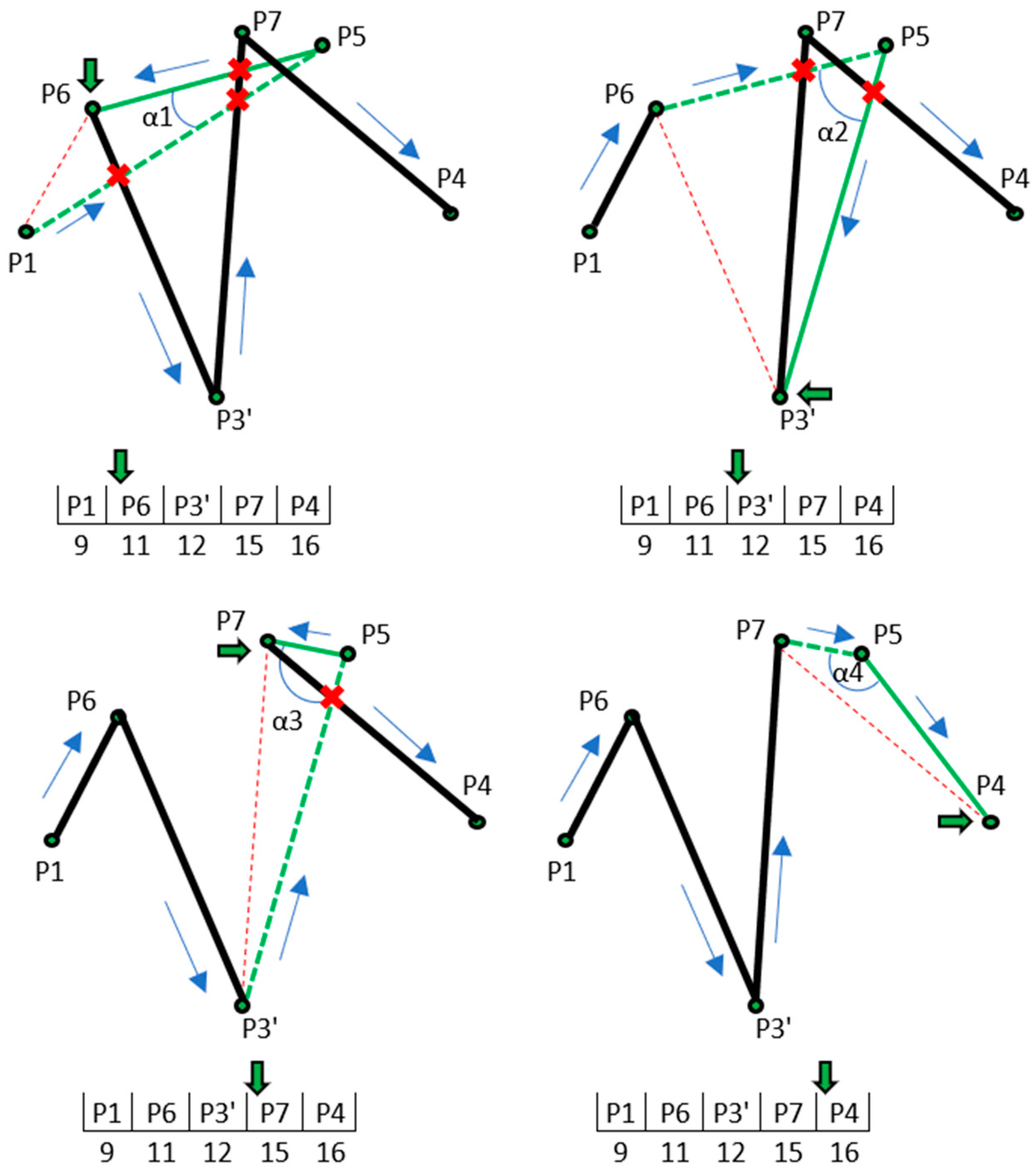
The straightest split refers to a configuration created by inserting a tentative point between two existing points where the two new line segments generated by the insertion form the angle closest to 180 degrees. In this context, we refer to the point currently being analyzed as the target point (Ptg). For both the tentative point (Pte) and the target point under consideration (Ptg), the algorithm generates two new tentative line segments and assigns an angle value to Ptg as follows (Figure 22):
  • Tentative segment 1 (ts1) is generated by connecting the Pte with the point previous to Ptg (marked as Ppr in Figure 19) (dashed green line).
  • Tentative segment 2 (ts2) is generated by connecting Pte with Ptg (solid green line).
The difference between the absolute value of the angle formed by two tentative line segments (α) and 180 degrees is the angle value (Av) assigned to Ptg. This can be expressed as Av = abs (180-abs(α)). Operationally, we seek the smallest Av (optimally equal to zero).
To test both requirements, consider the current configuration of points within the projected geometry range as the one depicted in Figure 21a. The algorithm starts scanning the points within the projected geometry range from the first point to the right of LRE. We avoid inserting at the LRE itself to prevent modifying the line segment outside of the projected geometry range.
The algorithm traverses all points (i.e., undeleted CRDT elements) within the projected geometry range and sequentially builds test line segments by connecting the two consecutive points (Figure 23). Each test line segment is tested for intersection with both tentative line segments. If any test line segment intersects (i.e., more formally, crosses) either of the tentative line segments, the target point is discarded as a potential candidate for insertion. The last Ptg to be tested is the RRE. If RRE produces the optimal configuration, pushing it to the right still complies with the operation’s intent, as it modifies the last line segment within the projected geometry range.
In the example depicted on Figure 20, inserting Pte at P5 is the only correct insertion (primary requirement), while it also produces the straightest split (angle α4 is closest to 180 degrees).
The final optimal position for inserting the tentative point is the position of a non-discarded target point with the straightest angle value attached (Figure 24). This example also demonstrates the benefits of implementing the relaxed updateShift approach. In the case that the strict updateShift is used, the algorithm would finish on step 2 since RRE would be on P3’, effectively producing an incorrect geometry output.
Given the tentative point Pte, with the associated projected geometry range RTop(LRE, RRE) and the current state of the CRDT data structure with all buffered operations integrated, the optimal position is found using Algorithm 2.
Algorithm 2. Positioning of a tentative point
bestAv=180, winningIdx=null
FOR each undeleted point from LRE+1 until RRE AS Ptg DO
              Generate ts1 and ts2
              Determine Av at current Ptg
              FOR each current line segment from LRE until RRE AS curLS DO
                            IF (NOT crosses (ts1,curLS)) AND (NOT crosses (ts2,curLS)) THEN
                                          IF Av<bestAv THEN
                                                                    bestAv=Av
                                                                    winningIdx=Ptg.idx
                                          END IF
                            END IF
              END FOR
END FOR
Upon completion, the value of variable winningIdx holds the new position to be used to generate the tentative operation’s integration parameters. Subsequently, the standard CRDT insertion algorithm is employed to insert the generated element.
By positioning the tentative point optimally within the projected geometry range, we respect the tentative operation’s original intent while enhancing the overall geometric output of combined local and remote operations.

5. Testing

5.1. Test System Implementation

We developed a test application using the Reference CRDT library [35] and OpenLayers (OL). To pack everything in a single HTML file, we converted the original Reference CRDT code from TypeScript to pure JavaScript using a TSC compiler [40]. The reference CRDT library provides three different integration algorithms (Sync9, YJS, AutoMerge) that share a common codebase for all supporting functions except for the actual integration algorithms. We implemented only the YJS version, but adding the other two should be a straightforward task. All business logic is implemented in JavaScript and executed exclusively on the clients (within web browsers).
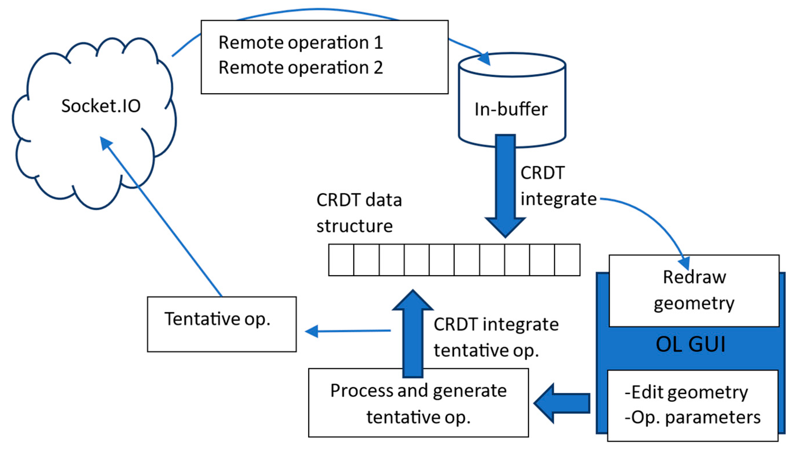
Distances are calculated from originLeft to each conflicting point during insertions and used for ordering conflicting inserts if they occur. Operations are generated upon OL modifying events using drag segments exposed by OL. Tentative operations are processed and integrated using the algorithm described in a previous chapter with the relaxed updateShift option implemented. All operations are exchanged via the Socket.IO channel [41]. A simple server running within NodeJS receives all the operations broadcasted by the clients and retransmits them to all other participating clients. The server performs no other CRDT relevant functions. On the clients, when remote operations are received, they first go into an in-buffer instead of being immediately processed (Figure 25).
If the user is not dragging when a remote operation is received, the operation is immediately processed from the buffer. Conversely, if the user is dragging, when they finish, all buffered remote operations are integrated sequentially. During the integration of remote operations, any required range end shifts for the tentative operation are also carried out. Finally, the tentative operation is integrated following the algorithm from Section 4.
The test implementation works on polygons with no inner boundaries (holes). The OL polygon data structure (with its last point identical to the first) is stripped of the last point and managed as is by the CRDT implementation. To produce correct polygons before each OL geometry redraw, the first point is simply copied to the last position. Additional mechanisms are implemented to correctly handle operations on and around the first polygon point (commented on in the source code).
For experimental purposes, to analyze various parameters of co-editing sessions, we implemented a simple event-recording mechanism. The system records the number of operations generated per client. For each conflict event, the system records its coordinates and whether it was resolved as a tentative operation or through low-level CRDT distance-based ordering. Data for each conflict are immediately sent over the Socket.IO channel to the controller client and visualized on its GUI. No other client except for the controller sees visualized conflicts.
The session duration (from the first session-wide operation processed to the last) of each session is also saved. For each point insert and point move edit during editing, the time spent dragging is recorded and accumulated per user and per session. At the end of each session, on each site, a simple geometry comparison checks whether or not it converged to the identical geometry.
In terms of the time complexity of tentative operations, the implementation directly depends on the time complexity of the underlying CRDT algorithms. In the case of Reference CRDTs, if we denote the number of all elements in the CRDT data structure by N and the number of elements with identical originLeft by C, the worst-case time complexity for remote inserts is O(C*N). This basically follows from the O(N) complexities of the view to the model mapping and the finding of elements by identifiers.
There are two aspects to the time complexity for tentative operations, the remote and the local. If a remote operation affects either of the local operation’s RRE/LRE, then the shifting of RRE/LRE to the previous or next undeleted element needs to be carried out. In extreme situations (e.g., a very large polygon with all but three points deleted), this could prove relevant as it will approach O(N).
The local aspect includes the view to model mapping when each local operation is initially generated, which inherits the CRDT complexity of O(N). Further, when each local operation is finalized, if it needs tentative processing, the first finding of an element by ID needs to be carried out (to find the current positions of LRE and RRE). This again inherits O(N) time complexity from the underlying CRDT implementation. Second, the final positioning algorithm visits all the non-tombstone elements between LRE and RRE (denoted by t) to find the optimal position for the tentative point, yielding O(t) complexity. The overall tentative operation processing time complexity is thus O(N+t) in the worst case. Since t will, as a rule, be small, it can be said that tentative operations do not add significant time complexity to that of the underlying CRDT mechanism. Readers interested in more details about the time complexity and performance of CRDTs are directed to an overview in [28] or, for example, to the original YATA paper [31].
The complete source code for both the server and the client is available from GitHUB (details in the Data Availability statement of this paper).

5.2. Experiment

Following extensive development level testing, which produced a stable implementation, we conducted an experiment using the developed implementation. The primary purpose of the experiment was to confirm in practice the theory described in the first part of this paper. Besides that, we also wanted to obtain insight into the frequency of conflicts and system behavior under different loads.
Following the primary purpose of the experiment, we defined the success/fail criteria to be convergence. If within each co-editing session all sites converge (end up with the identical state), we consider the implementation correct and the entire theory confirmed.
The secondary purpose of the experiment was to measure the success rate of the tentative operation mechanism, especially under increased loads. The higher the number of simultaneous co-editors, the higher the probability that conflicts will occur. In edge cases when two sites generate and transmit their operations simultaneously, the system will not be able to handle conflicts using tentative operations but will have to fall back to CRDT-based mechanics. In an ideal situation, even under high loads, the system would be able to resolve all or the majority of conflicts using tentative operations. Both the fail/success criteria and the tentative operations success rate were measured objectively, with the event-recording mechanism described in Section 5.1.
The primary purpose of real-time co-editors is to enable the users to perform work in an unconstrained manner and with predictable behavior. Hence, we also controlled the responsiveness and behavior of the implementation by collecting subjective feedback from the experiment’s participants.
Other types of geometric incorrectness, such as duplicated points, duplicated line segments, and self-intersections introduced by concurrent operations that do not conflict at the point level (not caused by the conflict resolution mechanisms), were not considered within the experiment.
In terms of the frequency of conflicts, we presumed that two aspects influence it. The obvious one is the number of sites participating in a co-editing session. Increasing the number of sites over an identical geometry being co-edited should increase the number of conflicts. The second, less obvious one is the shape of the geometry being co-edited. We presumed that long line segments, where many new points need to be inserted, could present situations where more conflicts occur. In contrast, the parts where existing points only need to be moved would probably generate less conflicts.
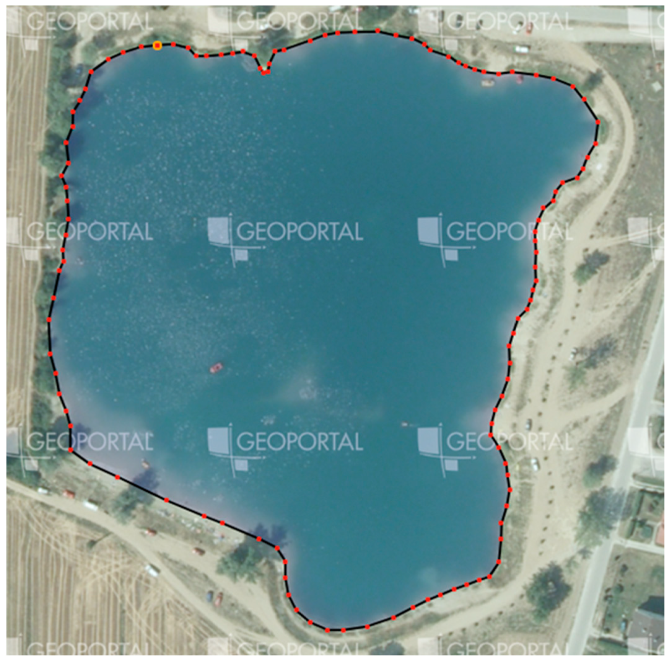
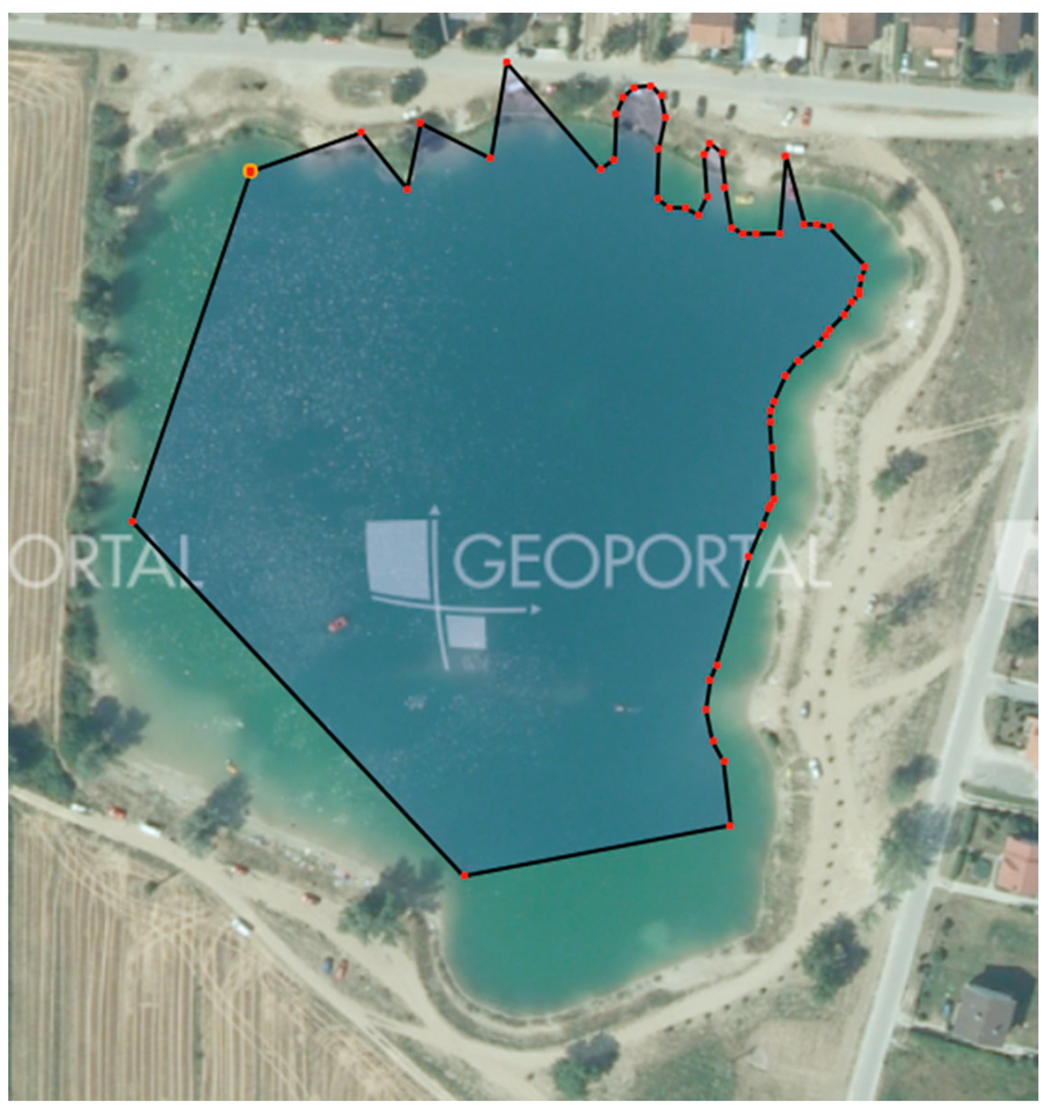
Having available only a limited number of users to participate in the experiment (up to 18 simultaneous users) and to create a situation with a higher probability of conflicts, we selected a target area that in vectorized form has only 120 points (Figure 26).
To test the system’s behavior in situations where mostly point inserts will be carried out on the one side and where mostly updates/deletes will be carried out on the other, we created an initial geometry as visualized in Figure 27. In theory, a few long line segments to the south and west should produce more conflicts than the significantly shorter ones to the east. Also, we wanted to see what happens in areas that require combined edits, including both updates and deletes, such as the one to the north. All co-editing sessions started from this identical initial geometry.
We conducted five runs, each with a different number of participants: five, seven, nine, twelve, and eighteen. Each run included two sessions carried out consecutively. All runs were conducted in a university computer classroom using 18 identical computers with mainstream hardware (Intel Core i5 13500T with 16GB of RAM). During all sessions, the latest version of the Google Chrome web browser (126.0.6478.127 64-bit) was used. The server was running on an outdated laptop (core i5 4300U CPU with 8 GB of RAM).
All participants received a brief introduction to the concepts of co-editing and were then asked to jointly vectorize the target lake with no other specific instructions. The controller client remained passive during all experiments, performing only the visual monitoring of the process and screen recording in case subsequent analyses of the system’s behavior were needed. Within the course of the experiment, participants did not report any problems with the system, and all sessions ended up with the identical final state, demonstrating convergence. Also, no anomalies were detected through the visual monitoring of the process on the controller client.
The results of all five runs (ten sessions) are given in Table 1. The results show that the tentative operation mechanism successfully handled all conflicts so none of the clients needed to resort to the low-level distance-based conflict resolution.
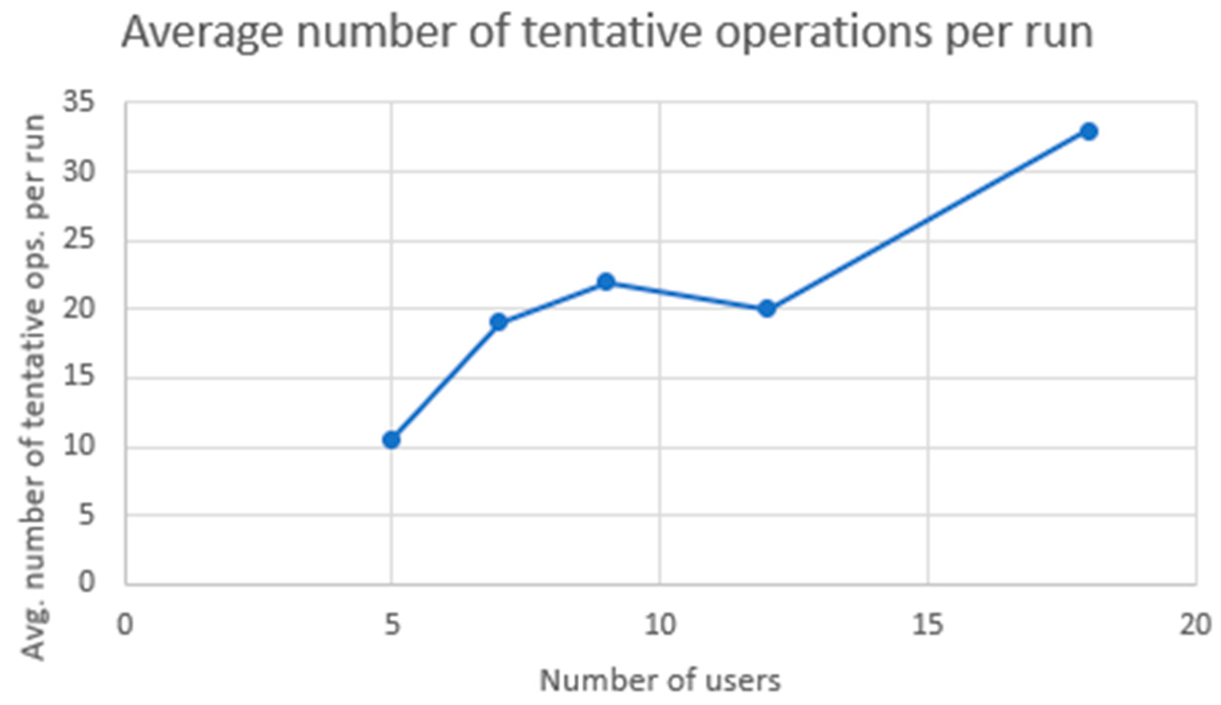
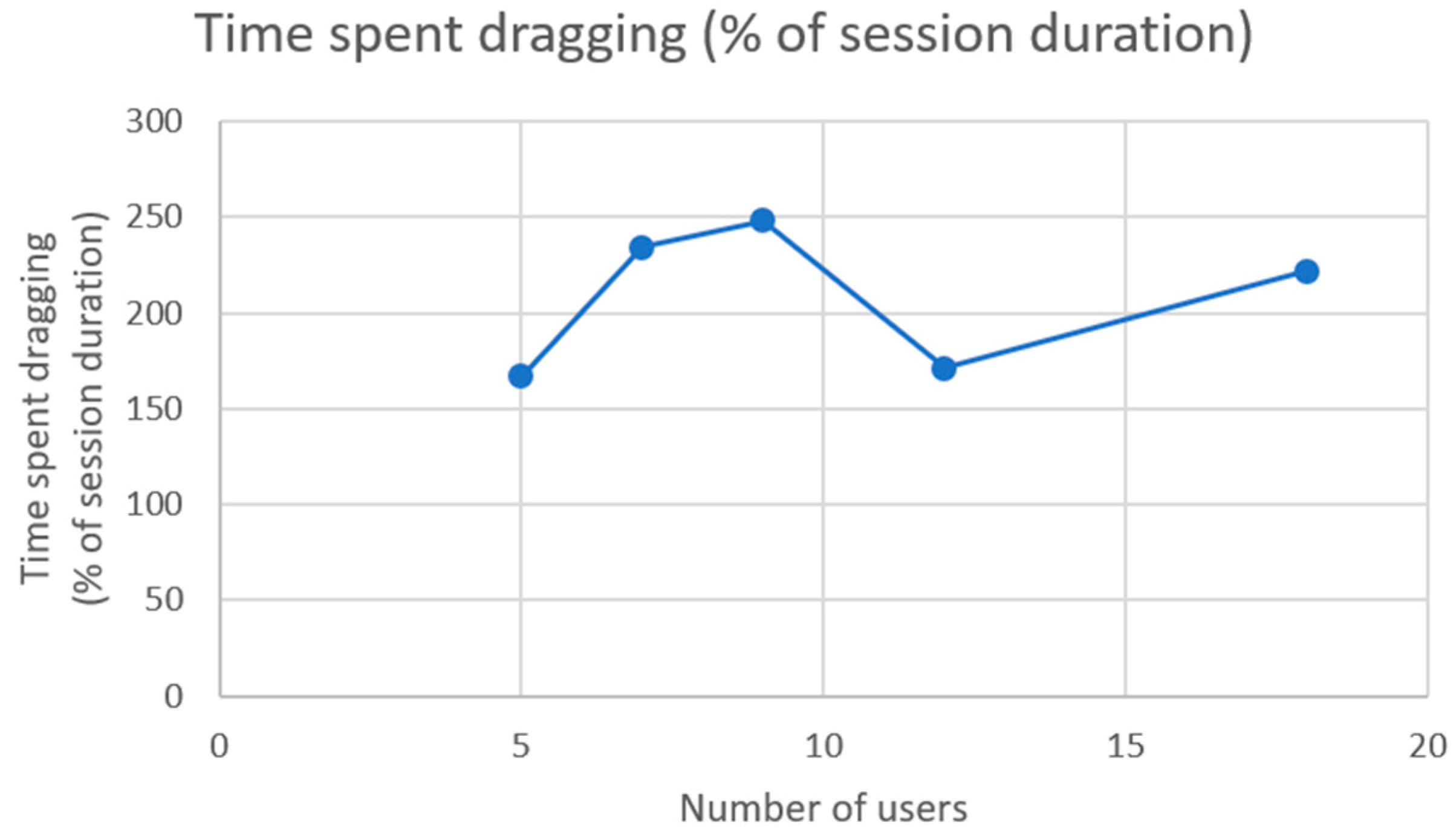
The averages of the number of tentative operations and of the accumulated time spent dragging, expressed as percentages of the session duration, are shown in Table 2.
As expected, the general trend of the increased number of tentative operations follows the increased number of users per session can be detected from the graph (Figure 28).
More interesting than that is the accumulated time that all the users spent dragging, expressed as the percentage of the sessions’ duration (Figure 29). Generally, it seems that the users can spend more than twice as much time dragging as the duration of a session.
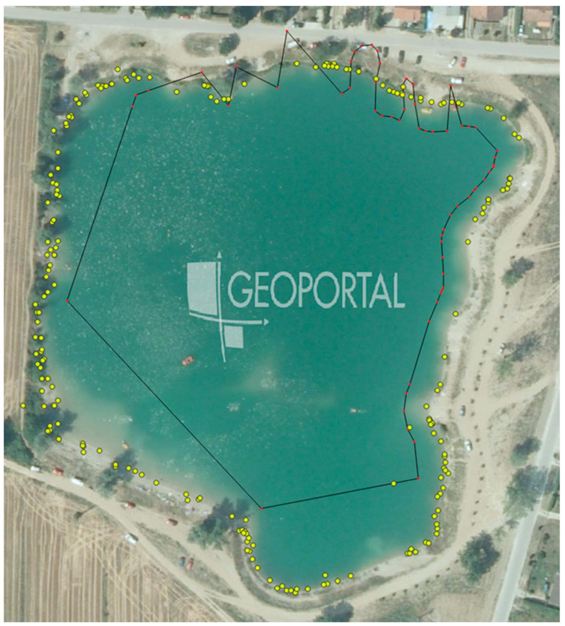
Next, we looked at the geospatial distribution of conflicts. Since we stored the coordinates of each processed tentative operation, we could visualize their locations overlaid on the initial polygon (Figure 30).
Two general trends can be anticipated from the visualization, basically confirming the intuitive assumptions we had. First, the area systematically populated by tentative operations is associated with long line segments on the original polygon, where many, potentially concurrent, inserts had to be carried out. Also, the part that needed significant and more complex revision (northeast) shows an increased population of conflicts. Second, the least populated area is to the right (east), where mostly simple updates were needed on short line segments. Although this does confirm the intuitive presumptions described earlier, it should only be considered as a very general trend. For instance, within two consecutive sessions where the same group of users was completing an identical task (as the Supplementary Videos from sessions 9 and 10 show) a completely different set of conflicts can be generated.

6. Discussion

This study aimed at two things. First, we wanted to investigate whether CRDTs, primarily devised for the co-editing of text, can be used to implement a geographic feature real-time co-editor. Second, we wanted to investigate what compromises have to be made to be able to resolve all conflicts automatically. Given the successfully conducted experiment with all co-editing sessions ending with full convergence on all sites and with no anomalies detected or reported by the participants, we concluded that the answer to the first question is positive. Standard CRDT algorithms really can be used to implement a geographic feature real-time co-editor. Further, the developed tentative operation concept proved extremely efficient since it successfully resolved all conflicts in such an extreme case where 18 simultaneous users co-edited a geometry made of 120 points. Coming to the second question, we found that there are some subtle but important differences between the requirements for text and geographic feature geometry co-editing.
In being based on the strong eventual consistency model, CRDTs, in general, do guarantee syntactic consistency. However, in addition to the one present in text, the syntactic consistency of geospatial data has another aspect: geometric correctness. As we have shown, a real-time geospatial feature geometry co-editor based on a straightforward CRDT implementation will be susceptible to geometric correctness issues. In a case where two concurrent points split the same line segment of a line string, convergence will be ensured by ordering the two points consistently on all participating sites in one of the two possible ways. However, in some cases, only one of the two orderings will be geometrically correct. Another issue with straightforward CRDTs is the integration algorithms being unable to correctly interleave concurrent operations in some cases.
Nevertheless, as we have shown, there are mechanisms, such as the described tentative operations, that can greatly reduce the probability of introducing geometric incorrectness during rapid real-time CRDT-based geometry co-editing. Unfortunately, this is only true during real-time sessions where all the users’ work is replicated among each other in real time. As soon as a user disconnects and starts working offline, in most cases, only standard CRDT mechanics will apply to the operations the user generates. As we have shown, standard CRDT mechanics can also be improved to better handle geometry but only up to a point.
Both optimistic and pessimistic traditional concurrency control approaches do not suffer from any of the described problems, but with a price of either reduced responsiveness (pessimistic case) or additional subsequent operator work to merge conflicting versions (optimistic case). Besides the reduced responsiveness, if traditional locking is to be implemented on the lowest-most point level, then a topological decomposition of geometric objects would also need to be carried out to achieve the ability to lock individual points. Further, although implementing traditional concurrency control techniques in theory seems easy, if a closer look is taken at the two relevant approaches, neither the Ethermap [10] (EM) nor the private view public view [5] (PWPW) really describes how conflicts are handled. The PWPW approach merely says that there is a synchronization procedure that publishes changes from private to public view, but with no hints as how potential conflicts are handled. The EM paper is somewhat more specific and says that conflicts are recorded without trying to resolve them automatically. The question to be answered is what happens to the feature that is in conflict before the conflict is resolved. If it is unavailable for further editing, then the situation is clear, and conflict resolution could probably be simple. However, the feature being unavailable for further manipulation before the conflict is resolved is a hinderance in the overall co-editing process. On the other hand, if the conflicting feature can be edited while still being in conflict (for instance, one of the conflicting versions is declared temporarily valid), then on this same feature, further conflicts can occur, creating multiple version forks that might later be a challenge to reconcile. Moreover, the scalability of such systems directly depends on the capabilities of the central server.
On the other hand, there are benefits to CRDTs over traditional concurrency control techniques. First, since all the conflicts are resolved automatically, operators can focus on the actual task instead of on resolving conflicts. Second, since all the business logic can be executed on the client side, requirements for central resources can be reduced to a bare minimum, only needing to carry out the session control and message exchange. Thus, the scalability of the CRDT-based approach should be superior to that of the traditional ones.
Without claiming that either of the approaches is better, they are different and will probably better fit different use cases. With real-time co-editing systems that require full consistency to always be enforced and where conflicts occur rarely, traditional approaches will probably be better suited. On the other hand, for short, concentrated ad hoc sessions where a single or a small set of geographic features are co-edited by many users, the CRDT approach, with its responsiveness and automatic conflict resolution, might prove more appropriate.
In the end, several limitations and open issues related to the described research need to be mentioned. First, this study only investigated geometry primitives made out of a single component. When multicomponent geometries start to be considered (e.g., polygons with inner boundaries—holes), besides the component-level operations (add, move, and delete point), at least the add and delete component operations will be needed. Those also need to be somehow incorporated into the co-editing framework. Further investigations are needed before anything can be called a complete framework. The two potential starting points for such a line of research can be found in the concept used in CAD-based solid modeling [18,19] or, even on the highest level (including non-spatial attributes), in the concept used in the Automerge framework, which focuses on the co-editing of JSON-like objects [34].
Second, this research only addresses handling geometry defects caused by inappropriate conflict resolution mechanisms. When more irregular geometries (i.e., with a less convex shape) are co-edited, the probability for the occurrence of geometric defects caused by non-conflicting operations will increase. Addressing this topic could be included into studies investigating higher-level operations on the geometry of geospatial features.
Third, during the experiments, a geometry with a limited number of points (hundreds) was used. Additional systematic tests should be carried out to find the limits in size of the geometry (the number of points) that the algorithm would be able to handle in real time. As a preliminary suggestion, we conducted some short, unsystematic testing using geometries with a much larger number of points (tens of thousands) and did not observe significant degradation in performance. The performance degradation will of course also depend on the hardware used on the clients and on the number of participants in the co-editing session.
Fourth, the experiments were conducted on a university internal network and with geographically collocated clients, where the replication of operations among participating clients occurred with minimal latency. Introducing the system to a less reliable environment (geographically dislocated sites connected over open, global networks) could impact the level of concurrency that the described approach was able to reduce since the latency that the replication of operations achieves would be increased.

7. Conclusions

This study investigated the applicability of CRDTs for the real-time co-editing of geospatial data on the lowest-most point level. Our research demonstrated that CRDTs can successfully manage concurrent edits on geospatial geometries points. Although the editing of geospatial geometry is conceptually similar to the editing of simpler data structures such as text, additional geometry-based improvements can enhance the overall behavior of a geospatial features’ co-editor based on CRDTs. By introducing the concept of tentative operations, we were able to reduce the concurrency in the system and, consequently, the number of insertion conflicts it can cause. Even in situations with an extremely high load (the number of simultaneous users per the number of the geometry’s points) where the probability of conflicts cannot be disregarded, the described approach proved stable and correct while enabling the users to carry out co-editing without any constraints.
Thus, we feel that the described approach could be particularly applicable for applications requiring many users to carry out unconstrained, rapid real-time co-editing of a single or a smaller set of geographic features. The results from the experiment we conducted underpin this and demonstrate the effectiveness of the algorithms developed within this research.
This study highlights the potential of CRDTs to open new use cases in the domain of real-time collaborative geospatial data co-editing. On the one hand, this could include more research and implementations of general purpose, Google docs-like real-time geospatial collaboration platforms, facilitate the development of real-time disaster/emergency response systems, etc. On the other hand, perhaps the ideas from this paper could increase both the scientific and industry level of interest in the co-editing of three-dimensional geospatial features, for instance, within the domain of 3d city models.
Despite the promising results, there are limitations and still open questions. Our testing was limited to reasonably experienced users (college undergraduate students in geomatics); only a single component, instead of the complete geospatial feature geometry, was considered; and short co-editing sessions were conducted in an internal University network (with very low latency).
Future studies could, on the one hand, explore the scalability of CRDTs when working with larger datasets and with geometries with larger numbers of points. Also, the behavior during longer co-editing sessions over less stable networks could be investigated. On the other hand, the real-time co-editing of complete geospatial features with geometries consisting of multiple components and with non-spatial attributes will require introducing another, more general level of concepts.
Finally, this research only investigated fixed-identifier CRDT family members. Variable-size identifier family members might have different benefits and drawbacks. Further, the other competing technology, operational transformation, could also be investigated for applicability, potentially with a different set of benefits and drawbacks.

Supplementary Materials

The following supporting information can be downloaded at https://www.mdpi.com/article/10.3390/ijgi13120441/s1: Video S1: Session 9 testing; Video S2: Session 10 testing.

Author Contributions

Conceptualization, Hrvoje Matijević; software, Hrvoje Matijević and Saša Vranić; validation, Hrvoje Matijević, Saša Vranić, Nikola Kranjčić, and Vlado Cetl; formal analysis, Hrvoje Matijević; investigation, Hrvoje Matijević; resources, Hrvoje Matijević, Saša Vranić, Nikola Kranjčić, and Vlado Cetl; data curation, Hrvoje Matijević; writing—original draft preparation, Hrvoje Matijević and Saša Vranić; writing—review and editing, Nikola Kranjčić and Vlado Cetl; visualization, Hrvoje Matijević; supervision, Vlado Cetl; project administration, Vlado Cetl; funding acquisition, Vlado Cetl. All authors have read and agreed to the published version of the manuscript.

Funding

The research was partially funded by University North, Croatia, through scientific projects UNIN-TEH-22-1-9 Possibilities of integration of building information models and geoinformation systems (2022) and UNIN-TEH-24-1-16. The role of geodesy and geomatics in the development of smart spaces (2024).

Data Availability Statement

Data and source code is available at https://github.com/HrvojeMatijevic/Geo-coeditor. Figure 26, Figure 27 and Figure 30 and the Supplementary Videos include digital orthophoto map—year 2011 in scale 1:5000 by the State Geodetic Administration of the Republic of Croatia accessed via the publicly available wms service at https://geoportal.dgu.hr/services/inspire/orthophoto_2011/wms and with the state of the data in June 2024.

Acknowledgments

The authors would like to acknowledge the students that helped with the testing part of this research. Special acknowledgments go to our colleague Mario Mađer for proofreading the manuscript and for useful advice on possible improvements.

Conflicts of Interest

The authors declare no conflicts of interest.

References

  1. Goodchild, M.F. Citizens as sensors: The world of volunteered geography. GeoJournal 2007, 69, 211–221. [Google Scholar] [CrossRef]
  2. JOSM Conflict Resolution. Available online: https://learnosm.org/en/josm/josm-conflict-resolution/ (accessed on 9 September 2024).
  3. Sun, Y.; Li, S. Real-time collaborative GIS: A technological review. ISPRS J. Photogramm. Remote Sens. 2016, 115, 143–152. [Google Scholar] [CrossRef]
  4. Weikum, G.; Vossen, G. Transactional Information Systems Theory, Algorithms, and the Practice of Concurrency Control and Recovery, 1st ed.; Elsevier Inc.: Amsterdam, The Netherlands, 2001; 201AD; ISBN 978-1-55860-508-4. [Google Scholar]
  5. Yaqin, S.; Chen, X.; Jinxiong, W.; Hang, Y.; Haibo, S.; Xiumei, Z.; Lin, Z. Development of a multi-view and geo-event-driven real-time collaborative GIS. Int. J. Digit. Earth 2022, 15, 134–147. [Google Scholar] [CrossRef]
  6. Kang, X. Graph-based synchronous collaborative mapping. Geocarto Int. 2015, 30, 28–47. [Google Scholar] [CrossRef]
  7. Seo, Y.H.; Kim, D.; Hong, B. Concurrent Updating of Large Spatial Objects. In Proceedings of the International Conference on Database Systems for Advanced Applications, Jeju Island, Republic of Korea, 17–19 March 2004. [Google Scholar]
  8. Jing, C.; Zhu, Y.; Fu, J.; Dong, M. A Lightweight Collaborative GIS Data Editing Approach to Support Urban Planning. Sustainability 2019, 11, 4437. [Google Scholar] [CrossRef]
  9. Van Oosterom, P. Maintaining consistent topology including historical data in a large spatial database. In Proceedings of the Auto-Carto, Seattle, WA, USA, 8–10 April 1997; pp. 327–336. [Google Scholar]
  10. Fechner, T.; Wilhelm, D.; Kray, C. Ethermap: Real-time Collaborative Map Editing. In Proceedings of the 33rd ACM SIGCHI Conference on Human Factors in Computing Systems, Seoul, Republic of Korea, 18–23 April 2015; ACM: New York, NY, USA, 2015; pp. 3583–3592. [Google Scholar]
  11. Shapiro, M.; Preguiça, N.; Baquero, C.; Zawirski, M. Conflict-free replicated data types. In Proceedings of the 13th International Conference on Stabilization, Safety, and Security of Distributed Systems, Grenoble, France, 10–12 October 2011; Springer: Berlin/Heidelberg, Germany, 2011; pp. 386–400. [Google Scholar]
  12. Gomes, V.B.F.; Kleppmann, M.; Mulligan, D.P.; Beresford, A.R. Verifying strong eventual consistency in distributed systems. Proc. ACM Program. Lang. 2017, 1, 1–28. [Google Scholar] [CrossRef]
  13. Ellis, C.A.; Gibbs, S.J. Concurrency control in groupware systems. In Proceedings of the ACM SIGMOD Conference, Portland, OR, USA, 31 May–2 June 1989. [Google Scholar]
  14. Preguiça, N.M.; Marquès, J.M.; Shapiro, M.; Letia, M. A Commutative Replicated Data Type for Cooperative Editing. In Proceedings of the 2009 29th IEEE International Conference on Distributed Computing Systems, Montreal, QC, Canada, 22–26 June 2009; pp. 395–403. [Google Scholar]
  15. Imine, A.; Molli, P.; Oster, G.; Rusinowitch, M. Proving correctness of transformation functions in real-time groupware. In Proceedings of the Eighth Conference on European Conference on Computer Supported Cooperative Work, Helsinki, Finland, 14–18 September 2003; Kluwer Academic Publishers: New York, NY, USA, 2003; pp. 277–293. [Google Scholar]
  16. Nichols, D.A.; Curtis, P.; Dixon, M.; Lamping, J. High-latency, low-bandwidth windowing in the Jupiter collaboration system. In Proceedings of the ACM Symposium on User Interface Software and Technology, Pittsburgh, PA, USA, 15–17 November 1995. [Google Scholar]
  17. Sun, C. Operational Transformation Frequently Asked Questions and Answers. Available online: https://www3.ntu.edu.sg/scse/staff/czsun/projects/otfaq/ (accessed on 13 February 2023).
  18. Lv, X.; He, F.; Cheng, Y.; Wu, Y. A novel CRDT-based synchronization method for real-time collaborative CAD systems. Adv. Eng. Inform. 2018, 38, 381–391. [Google Scholar] [CrossRef]
  19. Lv, X.; He, F.; Yan, X.; Wu, Y.; Cheng, Y. Integrating selective undo of feature-based modeling operations for real-time collaborative CAD systems. Futur. Gener. Comput. Syst. 2019, 100, 473–497. [Google Scholar] [CrossRef]
  20. Gao, L.; Xu, X. A New Algorithm for Real-Time Collaborative Graphical Editing System Based on CRDT. In Proceedings of the Computer Supported Cooperative Work and Social Computing, 13th CCF Conference, ChineseCSCW 2018, Guilin, China, 18–19 August 2018; Sun, Y., Lu, T., Xie, X., Gao, L., Fan, H., Eds.; Springer: Singapore, 2019; pp. 201–212. [Google Scholar]
  21. Burckhardt, S.; Gotsman, A.; Yang, H.; Zawirski, M. Replicated data types: Specification, verification, optimality. In Proceedings of the 41st ACM SIGPLAN-SIGACT Symposium on Principles of Programming Languages, San Diego, CA, USA, 22–24 January 2014; Association for Computing Machinery: New York, NY, USA, 2014; pp. 271–284. [Google Scholar]
  22. Shapiro, M.; Preguiça, N.M.; Baquero, C.; Zawirski, M. Convergent and Commutative Replicated Data Types. Bull. EATCS 2011, 104, 67–88. [Google Scholar]
  23. Oster, G.; Urso, P.; Molli, P.; Imine, A. Data consistency for P2P collaborative editing. In Proceedings of the 2006 20th Anniversary Conference on Computer Supported Cooperative Work, Banff, AL, Canada, 4–8 November 2006; Association for Computing Machinery: New York, NY, USA, 2006; pp. 259–268. [Google Scholar]
  24. Roh, H.-G.; Jeon, M.; Kim, J.-S.; Lee, J. Replicated abstract data types: Building blocks for collaborative applications. J. Parallel Distrib. Comput. 2011, 71, 354–368. [Google Scholar] [CrossRef]
  25. Weiss, S.; Urso, P.; Molli, P. Logoot: A Scalable Optimistic Replication Algorithm for Collaborative Editing on P2P Networks. In Proceedings of the 2009 29th IEEE International Conference on Distributed Computing Systems, Montreal, QC, Canada, 22–26 June 2009; pp. 404–412. [Google Scholar]
  26. Nédelec, B.; Molli, P.; Mostefaoui, A.; Desmontils, E. LSEQ: An adaptive structure for sequences in distributed collaborative editing. In Proceedings of the 2013 ACM Symposium on Document Engineering, Florence, Italy, 10–13 September 2013; Association for Computing Machinery: New York, NY, USA, 2013; pp. 37–46. [Google Scholar]
  27. Lv, X.; He, F.; Cai, W.; Cheng, Y. A string-wise CRDT algorithm for smart and large-scale collaborative editing systems. Adv. Eng. Inform. 2017, 33, 397–409. [Google Scholar] [CrossRef]
  28. Sun, D.; Sun, C.; Agustina; Cai, W. Real Differences between OT and CRDT in Correctness and Complexity for Consistency Maintenance in Co-Editors. Proc. ACM Hum. Comput. Interact. 2020, 4, 1–30. [Google Scholar] [CrossRef]
  29. Gentle, J. 5000× faster CRDTs: An Adventure in Optimization. Available online: https://josephg.com/blog/crdts-go-brrr/ (accessed on 9 September 2024).
  30. Gentle, J. I Was Wrong. CRDTs are the Future. Available online: https://josephg.com/blog/crdts-are-the-future/ (accessed on 9 September 2024).
  31. Nicolaescu, P.; Jahns, K.; Derntl, M.; Klamma, R. Near Real-Time Peer-to-Peer Shared Editing on Extensible Data Types. In Proceedings of the 2016 ACM International Conference on Supporting Group Work, Sanibel Island, FL, USA, 13–16 November 2016. [Google Scholar]
  32. Jahns, K. yjs. Available online: https://github.com/yjs/yjs (accessed on 9 September 2024).
  33. Automerge. Available online: https://github.com/automerge/automerge (accessed on 9 September 2024).
  34. Kleppmann, M.; Beresford, A.R. A conflict-free replicated JSON datatype. IEEE Trans. Parallel Distrib. Syst. 2017, 28, 2733–2746. [Google Scholar] [CrossRef]
  35. Gentle, J. Reference Crdts. Available online: https://github.com/josephg/reference-crdts (accessed on 9 September 2024).
  36. OpenLayers. Available online: https://openlayers.org/ (accessed on 13 February 2023).
  37. Herring, J.R. OpenGIS Implementation Standard for Geographic Information—Simple Feature Access—Part 1: Common Architecture; Open Geospatial Consortium: Wayland, MA, USA, 2011. [Google Scholar]
  38. Weidner, M.; Kleppmann, M. The Art of the Fugue: Minimizing Interleaving in Collaborative Text Editing. arXiv 2023, arXiv:2305.00583. [Google Scholar]
  39. Kleppmann, M.; Gomes, V.B.F.; Mulligan, D.P.; Beresford, A.R. Interleaving anomalies in collaborative text editors. In Proceedings of the 6th Workshop on Principles and Practice of Consistency for Distributed Data, Dresden, Germany, 25 March 2019; Association for Computing Machinery: New York, NY, USA, 2019. [Google Scholar]
  40. Typescript CLI Options. Available online: https://www.typescriptlang.org/docs/handbook/compiler-options.html (accessed on 9 September 2024).
  41. Socket.IO. Available online: https://socket.io/ (accessed on 9 September 2024).
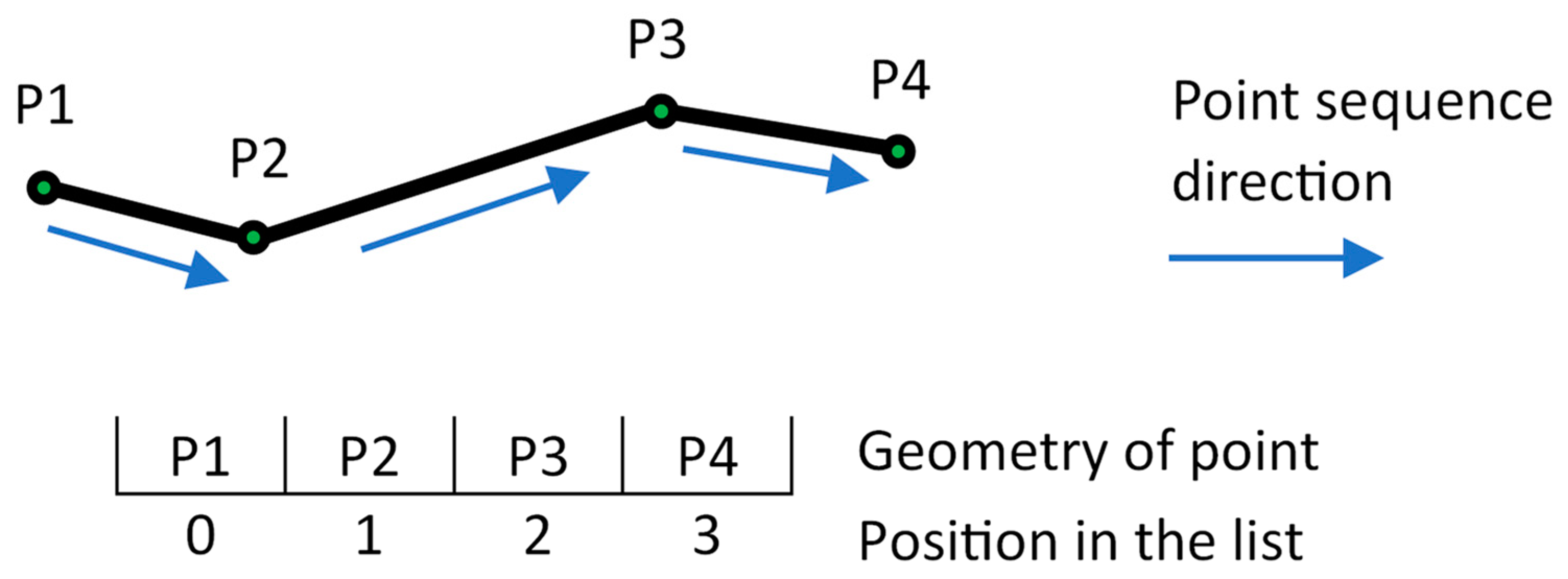
Figure 1. Linear geometry encoded as an array of points.
Ijgi 13 00441 g001
Figure 2. Two geometry edits handled by a geometry editing library (deleted points and line segments shown in red color and the new ones shown in green color).
Ijgi 13 00441 g002
Figure 3. Graphical notation used throughout the paper.
Ijgi 13 00441 g003
Figure 4. Two operations and their effects on various aspects of the CRDT data structure.
Ijgi 13 00441 g004
Figure 5. Two sites generating conflicting point-insert operations.
Ijgi 13 00441 g005
Figure 6. Conflicting insertions (a) geometrically ordered incorrectly and (b) geometrically ordered correctly.
Ijgi 13 00441 g006
Figure 7. Three conflicting points correctly ordered by distance from origin.
Ijgi 13 00441 g007
Figure 8. Three conflicting points geometrically ordered incorrectly by distance from origin.
Ijgi 13 00441 g008
Figure 9. Site 1 performing two sequential point inserts in forward direction.
Ijgi 13 00441 g009
Figure 10. Site 1 performing two sequential point inserts in backward direction.
Ijgi 13 00441 g010
Figure 11. Site 2 generating an operation in the same range as Site 1’s operations.
Ijgi 13 00441 g011
Figure 12. Effects of integrating Site 2’s operation on Site 1 in case Site 1 was editing (a) backward and (b) forward.
Ijgi 13 00441 g012
Figure 13. Geometry range of tentative (a) insert and (b) update operations.
Ijgi 13 00441 g013
Figure 14. Effect of executing deleteShift on LRE.
Ijgi 13 00441 g014
Figure 15. A concurrent remote UPD(P3’, P3).
Ijgi 13 00441 g015
Figure 16. Effect of executing (a) strict updateShift (RRE) and (b) relaxed updateShift (RRE).
Ijgi 13 00441 g016
Figure 17. Two edits carried out by (a) Site S1 and (b) Site S2.
Ijgi 13 00441 g017
Figure 18. The result of integrating S1’s and S2’s operations.
Ijgi 13 00441 g018
Figure 19. Another two edits carried out by (a) Site S1 and (b) Site S2.
Ijgi 13 00441 g019
Figure 20. Final result of all S1’s and S2’s operations.
Ijgi 13 00441 g020
Figure 21. The final range of (a) S0’s Top and (b) S0’s Top integrated using original parameters.
Ijgi 13 00441 g021
Figure 22. Tentative segments and angle value assigned to a target point.
Ijgi 13 00441 g022
Figure 23. Configurations for inserting a tentative point at the four target points.
Ijgi 13 00441 g023
Figure 24. Final result of integration of tentative operation.
Ijgi 13 00441 g024
Figure 25. Architecture of integration OL-CRDT.
Ijgi 13 00441 g025
Figure 26. Target area and vectorized polygon.
Ijgi 13 00441 g026
Figure 27. Initial polygon.
Ijgi 13 00441 g027
Figure 28. Graphical visualization of average number of tentative operations per run.
Ijgi 13 00441 g028
Figure 29. Graphical representation of the percentage of the time spent dragging related to session duration.
Ijgi 13 00441 g029
Figure 30. Locations of tentative operations from all sessions.
Ijgi 13 00441 g030
Table 1. Summary of testing sessions.
SessionNo. of ParticipantsNo. of EditsNo. of Upd. and Ins. EditsNo. of Tentative
Operations
Session
Duration (s)
Accumulated Dragging Time (s)
15144124773128
25108102146095
371961772391201
471451261551126
591711682365145
691541462154147
7121741462498156
8121411171662113
9182341974358141
10181991612356112
Table 2. Averages per run.
Number of UsersAvg. Number of Tentative
Ops per Run
Time Spent Dragging
(% of Session Duration)
510.50167
719.00234
922.00248
1220.00171
1833.00222
Disclaimer/Publisher’s Note: The statements, opinions and data contained in all publications are solely those of the individual author(s) and contributor(s) and not of MDPI and/or the editor(s). MDPI and/or the editor(s) disclaim responsibility for any injury to people or property resulting from any ideas, methods, instructions or products referred to in the content.