In recent years, several advances have been made in the development of SAR-based flood extent mapping techniques (e.g., [
14,
16,
21,
22]), new methods have been set up for deriving water levels from SAR, combining digital elevation (DEM) data ([
10,
23]), and in ways to integrate this added-value data in prediction models, either in near-real time through assimilation or subsequent recalibration (e.g., [
15,
18,
25]). For a comprehensive review of relevant flood remote-sensing research activities, readers can refer to [
29]. The proposed study aims to go beyond flood extent mapping calibration through SAR images with a view to showing the potential of these images in spatio-temporal floodwater depth characterization in extremely flat areas with complex topography (e.g., levees, banks, bridges, etc.), while also considering the impact of the timing of SAR image acquisition.
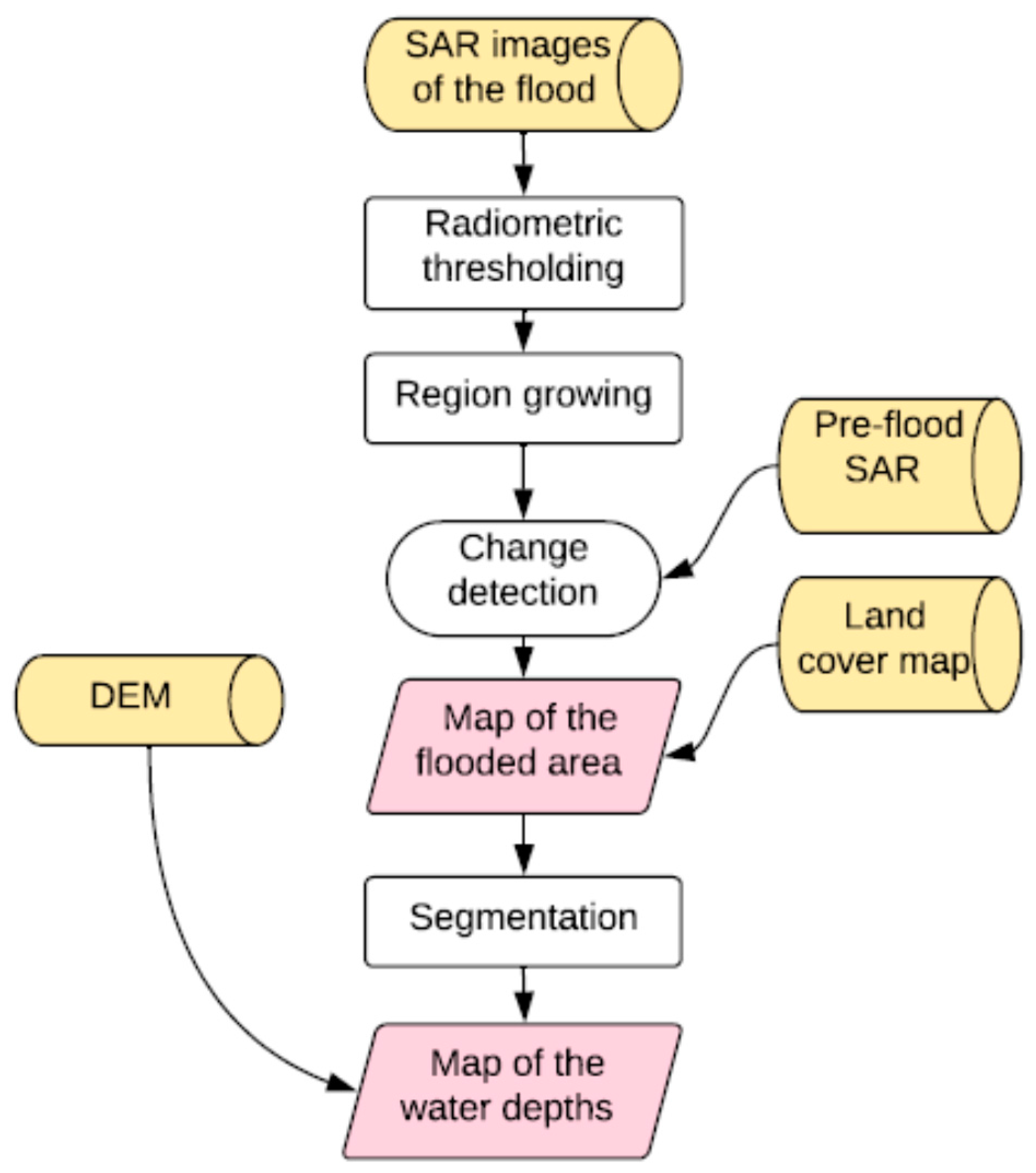
The proposed methodological framework, proposed in
Figure 2, utilized to build the event scenarios for the Bradano case study and to monitor the spatio-temporal dynamic of floodplain drainage is described in this section. In particular, the section presents the flood mapping algorithms to extract flood extent layouts using SAR images (
Section 3.1) that are, later, combined with a DEM in order to extract water-depth maps in a flat terrain with complex topography (
Section 3.2). Subsequently, using these hazard-derived SAR and DEM images, acquired respectively near the flood peak and in the recession stage of the flood event, the processes adopted to constrain (at different floodplain points and in different time instants) a 2D hydraulic model (presented in
Section 3.3), limiting the uncertainty of roughness parameters, are proposed in
Section 3.4.
3.1. SAR Image-Processing Algorithm for Flood Extent Extraction
The most commonly used SAR flood extent mapping techniques include simple visual interpretation (e.g., [
33]), image texture algorithm [
29], supervised classification and various multi-temporal change detection methods (e.g., [
18,
34]).
However, one of the most commonly adopted methods for distinguishing between flooded and non-flooded areas is the interpretation of radar signatures (e.g., [
21,
22]). The specular reflection of the radar signal is the main electromagnetic mechanism producing a high contrast in SAR images between flooded and non-flooded areas [
14]. In general, floodwater that is covering the terrain is much smoother than the surrounding non-flooded land and reflects most of the impinging radar signal toward the specular direction, so backscatter is very low and flooded areas appear dark in shade [
21]. This advantage of SAR data for flood mapping means computation efficiency for flood detection and monitoring algorithms that could make them suitable for supporting delineation of flood hazard scenarios requiring emergency management. Conversely, inundation mapping may be complicated by wind roughening and by vegetation emerging from water, producing high radar return that decreases the contrast between flooded and non-flooded areas in SAR images: for example, the scattering from a well-developed canopy becomes predominant and the presence of the underlying water is hardly detected by the radar [
21].
In this light, the flood mapping procedure utilized in this study is basically a semi-automatic classification in which the integration of different rules is performed based not only on SAR but also on ancillary data, such as knowledge of land cover and information derived from a reference pre-flood SAR image.
The utilized methodology for flood extent extraction follows the steps proposed by [
18]. It is comprises (i) SAR image radiometric thresholding to extract the water body core, (ii) a region-growing approach in which the backscatter of image pixels is compared to check the similarity with the value of the nearest neighbor seed pixel, i.e., bodies of water, in order to extract all areas covered by water; finally, the utilized approach takes advantage of (iii) SAR change detection capabilities by exploiting two images acquired before and during the flood to monitor backscattering changes caused by the flood event. Change detection thus aims to remove from the flood extent map pixels that do not correspond to floodwater. To do so, only pixels that change their backscatter values significantly with respect to their baseline values are kept in the final flood extent map [
18].
By using a couple of SAR images (one flooded and one unflooded) change detection can reduce the false alarm probability arising from shadow areas, which appear as dark as the flooded pixels. Only pixels that change their backscatter values significantly in the two images are kept in the flood extent. RGB composition is used for this end: pre-flood and post-flood images are co-registered, each to a single master scene, and are combined into a color image to identify the flooded areas better in comparison to permanent water and other classes. SAR intensity images were filtered through a Lee filter [
35], also with an 11 × 11 sliding window pixel size, and then converted to a logarithmic scale. Subsequently, a numerical comparison of the different values of the two SAR images distinguishes between flooded and unflooded areas more easily. This scheme was used extensively in past literature studies (see [
18,
23,
34]), but it can be complicated by a wealth of other factors influencing the actual backscattering level of the terrain, which include surface roughness and soil moisture for land areas, the presence of capillary waves for bodies of water, or the presence of rain during acquisition. For example, wind may cause capillary waves in free water surfaces of large size, which may then increase the local backscatter level of SAR images. Moreover, the speckle noise inherent to all the coherent imaging devices causes statistical fluctuations in the backscattering levels of single pixels. All of these factors often become critical during flood events so the knowledge of land cover at 1:5000 scale, available from the Regione Basilicata geoportal (
http://rsdi.regione.basilicata.it/) and detailed at finer scale through an orthophoto visual interpretation, was utilized by an operator to understand, for example, if it was necessary to look for dark spots in the image (bare soil) or to some increase in intensity with respect to an image taken before the flood event (e.g., over forested areas). Although the proposed procedure aims to make radar interpretation as automatic as possible, a certain degree of supervision by an expert operator was considered to be essential to reduce uncertainties arising in SAR flood mapping. For example, the presence of permanent tree vegetation, characterized by low penetration of electromagnetic waves through leaves and branches, makes it difficult to detect the presence of water below the canopy. Indeed, taking into account that (i) mapping flooded vegetation can be still considered a critical issue for operational inundation mapping using SAR data [
36] and (ii) being aware that the aim of the proposed research is to contribute to scientific knowledge in the field of operational methods and models for real-time flood damage assessment, the area inside the river channel and the pinewoods that is closer to the river mouth were excluded from the calibration. Indeed, these parts of the study area are characterized by the presence of very dense and high vegetation without involving vulnerable elements so floods cannot produce direct damage in these zones.
3.2. Water Depth Estimation Combining SAR Images and a Digital Elevation Model
Although exploitation of river inundation satellite images, especially for operational applications, is mostly restricted to flood extent mapping, there is significant potential for improvement in a three-dimensional characterization of floods (i.e., flood-depth maps) using SAR satellite images.
When considering that estimation of water levels plays an essential role in quantifying potential flood event damage so control action can be taken during the emergency phase ([
37]), the flood extent limits extracted by the SAR image here were combined with a Digital Elevation Model (DEM) allowing extraction of the terrain elevations inside all relevant limits and, thus, the estimation of elevation difference intervals across the surrounding topography (within the flood limits).
The Basilicata Basin Interregional Authority provided the authors with a plano-altimetric survey of the study area using laser-scanning technology and digital aerial photogrammetry. The airborne laser scanner system is an active remote-sensing sensor technique, that couples a laser attached to an aircraft with precise kinematic positioning provided by a differential global positioning system (DGPS) to produce accurate elevation measurements [
38]. Data acquired from the Bradano River mouth area was formulated by a Topeye MKII system, which works in full waveform in order to provide a better description of all ground elements. Indeed, it is able to record multiple echoes besides the first and the last pulse ([
39,
40]). In area characterized by more complex topography, a flight was made at 600 m with an orthophotos resolution of 5 cm and a laser density of 40 pt/m
2. The resulting laser scanner points cloud had a vertical accuracy of about 0.15 m and horizontal accuracy of 0.30 m. When considering that the increase of DEM resolution corresponds to exponential computational time growth in hydraulic model simulation performance, it was considered appropriate to guarantee high altimetric detail of the hydraulic elements that have most influence on water flow (such as river reach dimension, cross-sections, banks, and levees, etc.), through manual manipulation rather than using an excessively detailed DEM grid resolution size [
41]. Therefore, a square grid of 10 m resolution was used for input of the 2D hydraulic model, while the geometries of the most important hydraulic elements were entered in the grid to maintain good characterization of study area topography. Indeed, resolution should be chosen in relation to model structure and complexity, which always have limitations [
42]. For instance, the FLORA-2D model cannot include inertial terms in governing equations, and therefore has low sensitivity to small-scale DEM features, meaning that close field flow processes are smoothed out, even when high-resolution grids are used [
43].
Finally, it is important to note that finer grid resolution would require a more complex parameterization of the 2D hydrodynamic model, and, as consequence, it could increase the uncertainty of head losses and roughness [
44]. Within this framework, the method for incorporating available topographic data into the model structure is the key to achieving the best compromise between detail (or precisions), maximum expected accuracy (which depends more on available dataset than on grid resolution), and computational efficiency [
42]. In our opinion, the use of subgrid treatments, when combined with appropriate upscaling of resistance parameters, would, in many instances, be a suitable approach to making better use of available topographic details, while being consistent with the uncertainty related to model structure and other input data available for model-building and evaluation.
Previous studies (e.g., [
10]) have derived water levels by computing the differences in elevation between each grid cell and the elevations of the flowpath-connected downslope grid cell where the flow enters the channel. This method is based on the law stating that hydraulic energy decreases from upstream to downstream. Using the assumption of one-dimensional (1D) modeling on flow direction, Hostache et al. [
10] successfully determined a hydraulic hierarchy, composed of an up/downstream relationship between points of water-level estimation, corresponding to the sites of relevant limits. Consequently, following this approach, the water-level estimates in an area with gentle relief imply significant uncertainty. Thus, the method proposed in [
10] cannot be applied with good results in extremely flat area where the extent of the flooded area is calculated through water transfer from neighboring cells alongside and perpendicular to the river.
In flat topography, the water level usually coincides with terrain elevation on the cells where there is wet–dry shift, i.e., on the relevant flood limits, with gradual floodwater depth increase moving away from these boundary cells. It is particularly true in areas with complex topography where water flow is confined by structural elements (e.g., levees, banks, bridges).
In this study, a three-step method is proposed for water-depth assessment in flat areas with complex topography. First, (i) the segmentation of the flood extent extracted from the SAR images is performed to localize the flooded area (segmentation block), which makes it possible to assume uniform flow, i.e., a horizontal water level. While the river channel is characterized by a slope oriented in the direction of the water flow, the complex topography (i.e., levees, embarkments etc.) of the floodplain area can confine water flow, which may be stagnant in some points as identified by the SAR images in different moments of the flood event. Since the segmentation step is not the primary aim of this paper, an expert operator used orthophoto maps to identify the presence of overhead structural elements (typically non-flooded cells) able to confine water flow. Next, (ii) the maximum water level of each segmentation block was estimated as the mean of the terrain elevation values included in a 95–100 percentile range of the DEM cells that are located along the boundaries of the analyzed block; Finally, (iii) the water depth of each pixel within the considered block was evaluated as the difference between the water level value estimated in the previous step and the terrain elevation values of the cells.
3.3. Flood Inundation Modeling
In this study, the FLORA-2D hydraulic model [
45] was used to simulate flood dynamics and the extent of two Bradano River flood scenarios referred, respectively, to November 2010 and December 2013, described in
Section 2. The two-dimensional hydrodynamic model, already proposed in [
45], is based on the numerical solution of a simplified subset of an equation derived from Navier-Stokes shallow water equation formulation. It was developed with the aim of simulating flood propagation in flat areas, taking into consideration the dynamic spatio-temporal effect of vegetation. Indeed, the topography and land-use roughness are the most critical factors in 2D hydraulic modeling [
46], as they influence estimation of flood extension and its flow characteristics, like water depth that can be considered the main factor of flood losses according to [
9]. The numerical solution was developed for the specific needs of providing a good compromise between simulation time and data accuracy for a correct representation of the process [
37], namely to obtain high computational efficiency through the use of a simplified set of initial and boundary conditions.
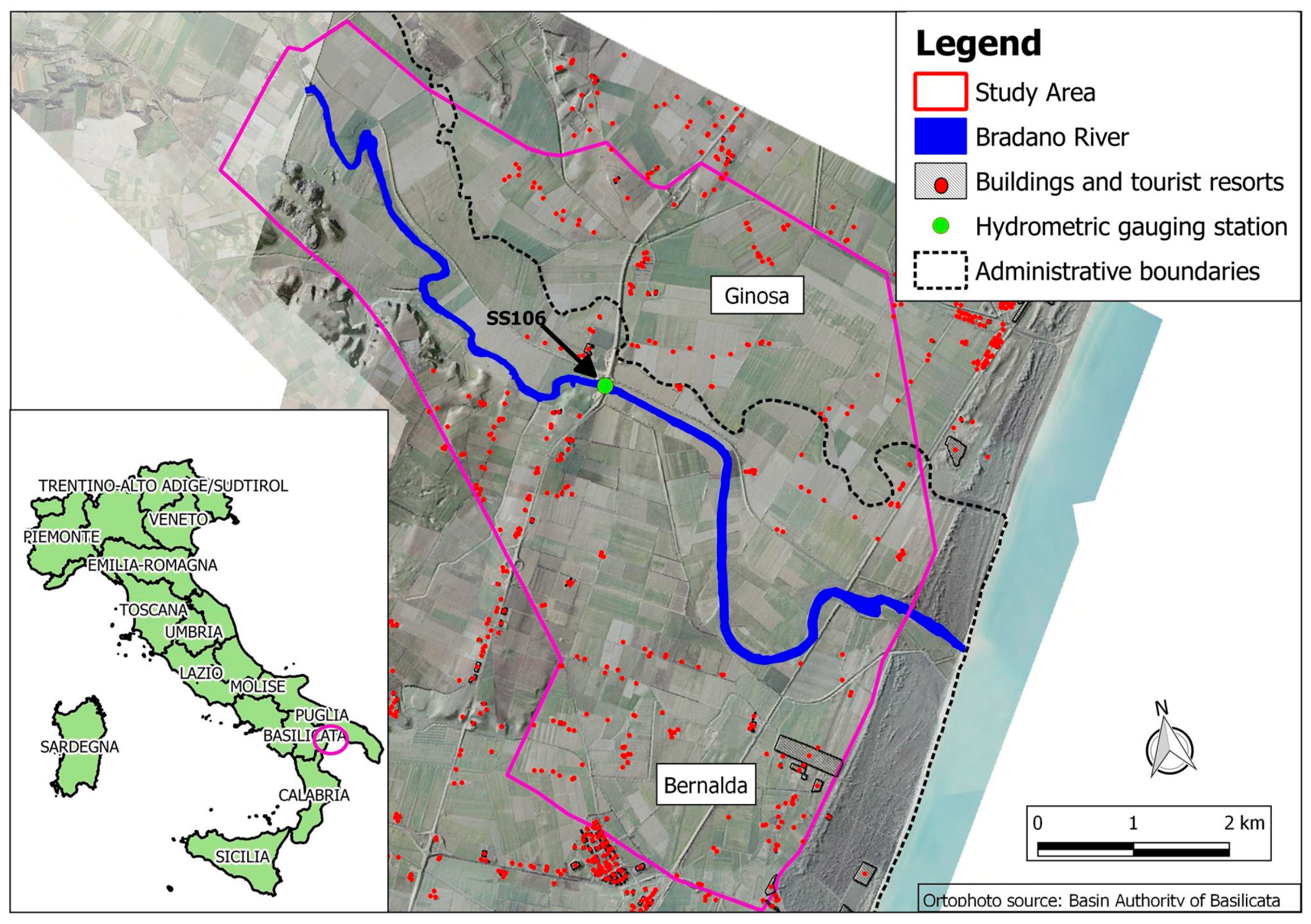
The initial flood stage condition was a null riverbed water level. Moreover, the upstream boundary condition was constructed by considering the effective water depth measurements along the river, available as readings from a gauge station in the analysis area, called S.S. 106 (see
Figure 1). Conversely, in [
45,
47] the authors used the output of the hydrological model as a boundary condition simulating FLORA-2D for the 1 March 2013 Bradano flood event, (not analyzed in this study), because the information that was recorded by the S.S.106 hydrometric station was not available due to malfunctions caused by the impact of the flood. The above-mentioned hydrometric levels were assigned as upstream boundary conditions, while a constant water level equal to 0.5 m a.s.l. was considered a downstream boundary condition (sea level was assumed to be slightly above standard conditions). Finally, the spatial distribution of flow resistance was derived from LiDAR data, used to generate maps of vegetation heights [
48]. In this application, the computational domain was defined by a square grid with a resolution of 10 m, while the time step was set to 2 s to ensure model stability.
3.4. Hydraulic Model Calibration Framework Using SAR- and DEM-Derived Flood Maps
Several studies have pointed to hydraulic roughness as a dominant factor for relatively shallow inundation ([
10,
49,
50,
51]) in particular for 2D hydraulic models ([
25,
52]), as it can affect flood extent, timing of flood waves, and localized processes such as location of hydraulic leaps. Moreover, recent research has highlighted that roughness parameters are the chief factors in deciding the rate of flooding and receding, and thus their calibration heavily depends on the timing of the SAR images ([
15,
53]) during model calibration as in the proposed study. Hence, we decided to restrict FLORA-2D model calibration to Manning coefficients considered the most important parameters, but also the main source of uncertainty ([
43,
54]), especially in an area with a gentle and flat topography where we can consider that friction and ground slope in a gravity wave have the same order of magnitude within the energy equation, controlling flow characteristics even though it is acknowledged that several parameters (e.g., related to roughness, channel cross-section dimensions, initial condition) can influence model results.
In particular, the Manning (roughness) coefficient is a spatio-temporally-distributed parameter that changes over space (e.g., bed channel versus vegetated floodplains) and time (e.g., seasonal changes of vegetation or temporal resistance variation due to vegetation). However, variable spatio-temporal Manning coefficients of this kind cannot be measured in real world applications [
15]. Moreover, this parameter is generally determined under uniform flow conditions rarely observed in an area characterized by flat and complex topography.
Thus, Manning coefficient values are regarded in literature as parameters that may vary widely. Classes of coefficient have been drawn up for the different land use categories to be used as parameters, which are estimated using model calibration.
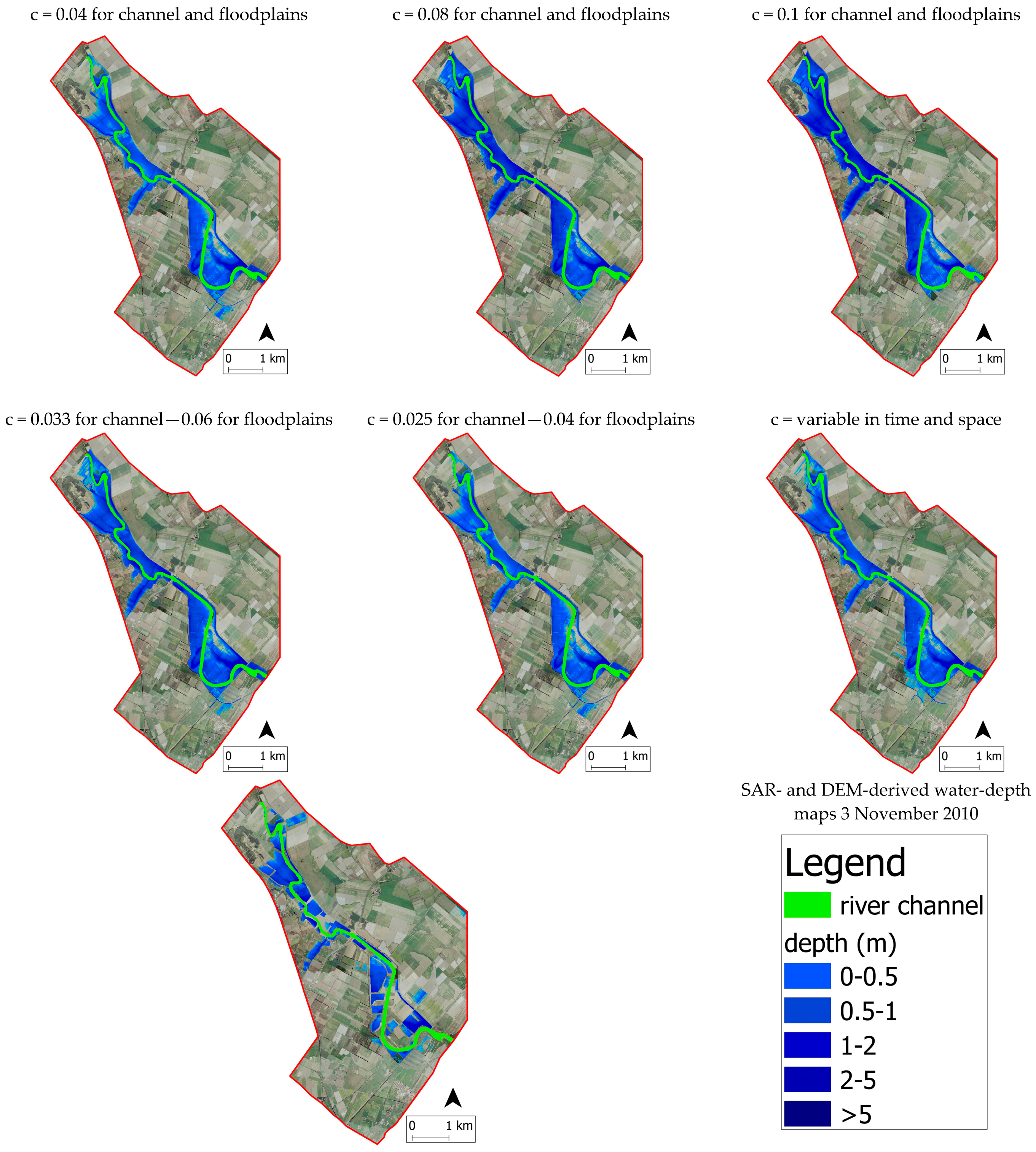
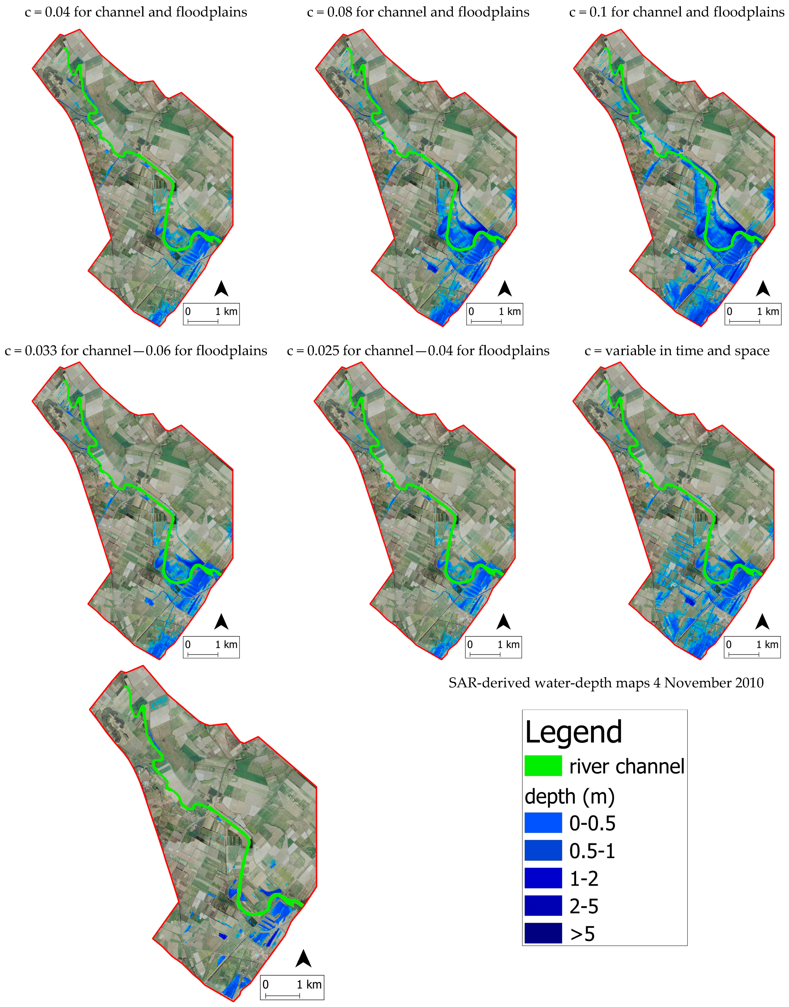
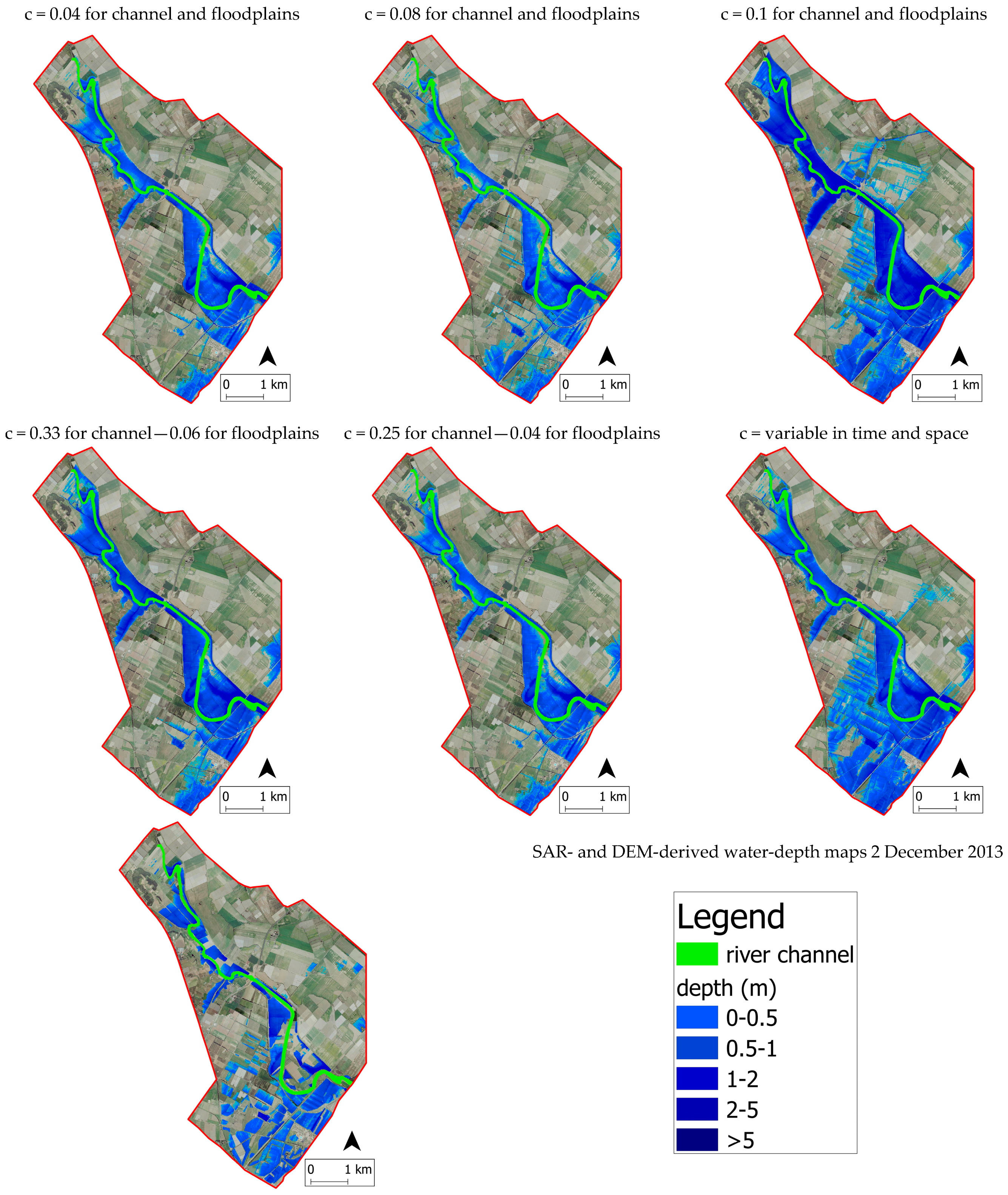
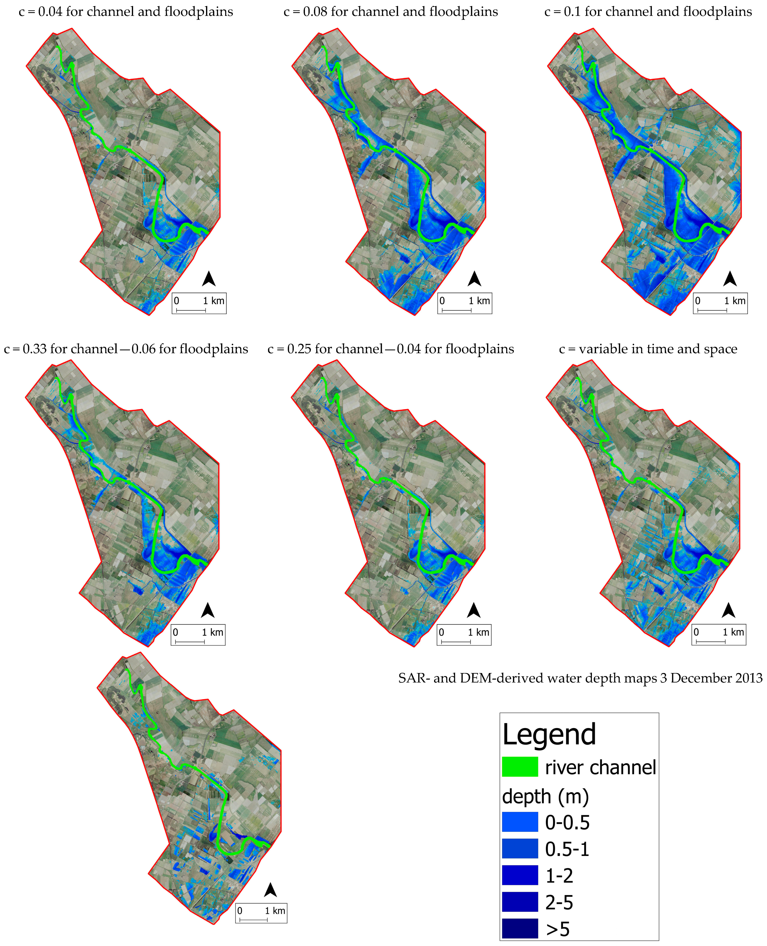
For this purpose, a set of model runs corresponding to a set of plausible Manning coefficient values was carried out, assuming that the Manning roughness values may lie between 0.04 and 0.1. A low roughness coefficient of 0.04 represents quite a clean channel, i.e., covered by grassland, whereas a high roughness coefficient of 0.1 would represent a channel with very thick vegetation. We therefore performed three simulations with roughness coefficients, respectively, of 0.04, 0.08, and 0.1 for the whole area. Later, we distinguished between the Manning coefficients in the main channel and floodplain assuming they were temporally and spatially constant. When considering that the Manning coefficient for the channel was higher than in the floodplain, we performed another two simulations that has, respectively, (i) a Manning coefficient value of 0.033 in the channel and 0.06 elsewhere, representing a wet season; and, (ii) 0.025 in the main channel and 0.04 in the floodplains, representing a dry season in which vegetation is quite sparse and low.
In this way, Manning coefficient values in the floodplain, which can be considered the area of greatest influence due to its sheer extension, varied in regular steps of 0.02 in these five simulations (i.e., 0.04, 0.06, 0.08, 0.1). Finally, for the last hydraulic simulation, we used variable spatio-temporal Manning coefficients that can take into consideration the dynamic effects of vegetation: cell roughness varies with floodwater depth according to a low that depends on the type of vegetation, as in [
45]. In particular, Manning coefficient n is calculated according to [
55] when vegetation is rigid, and [
56] in the case of flexible vegetation. The step size for the Manning coefficient was explored over a fixed grid of 10 m cell resolution for all of the model runs.
To emphasize the integration of SAR-derived datasets instead of traditional calibration data, e.g., hydrographs, a two-step approach was adopted.
The first step of the calibration procedure is based on flood extent maps derived from a temporal series of SAR images (resampled, avoiding unsustainable computational times, at the same resolution as the hydraulic model, i.e., 10 m) for the 3–4 November 2010 Bradano event. The FLORA-2D hydraulic model does not have a routine that is able to simulate soil water infiltration and does not therefore account for soil permeability. Hence, water-depth values of less than 0.1 m could be not considered to be significant in the model results because cannot influence assessment of flood losses [
9]. To guarantee the consistency of calibration and validation processes, the pixels in the SAR- and DEM-derived and in the hydraulic model flood maps were labeled as flooded where water depth exceeded 0.1 m.
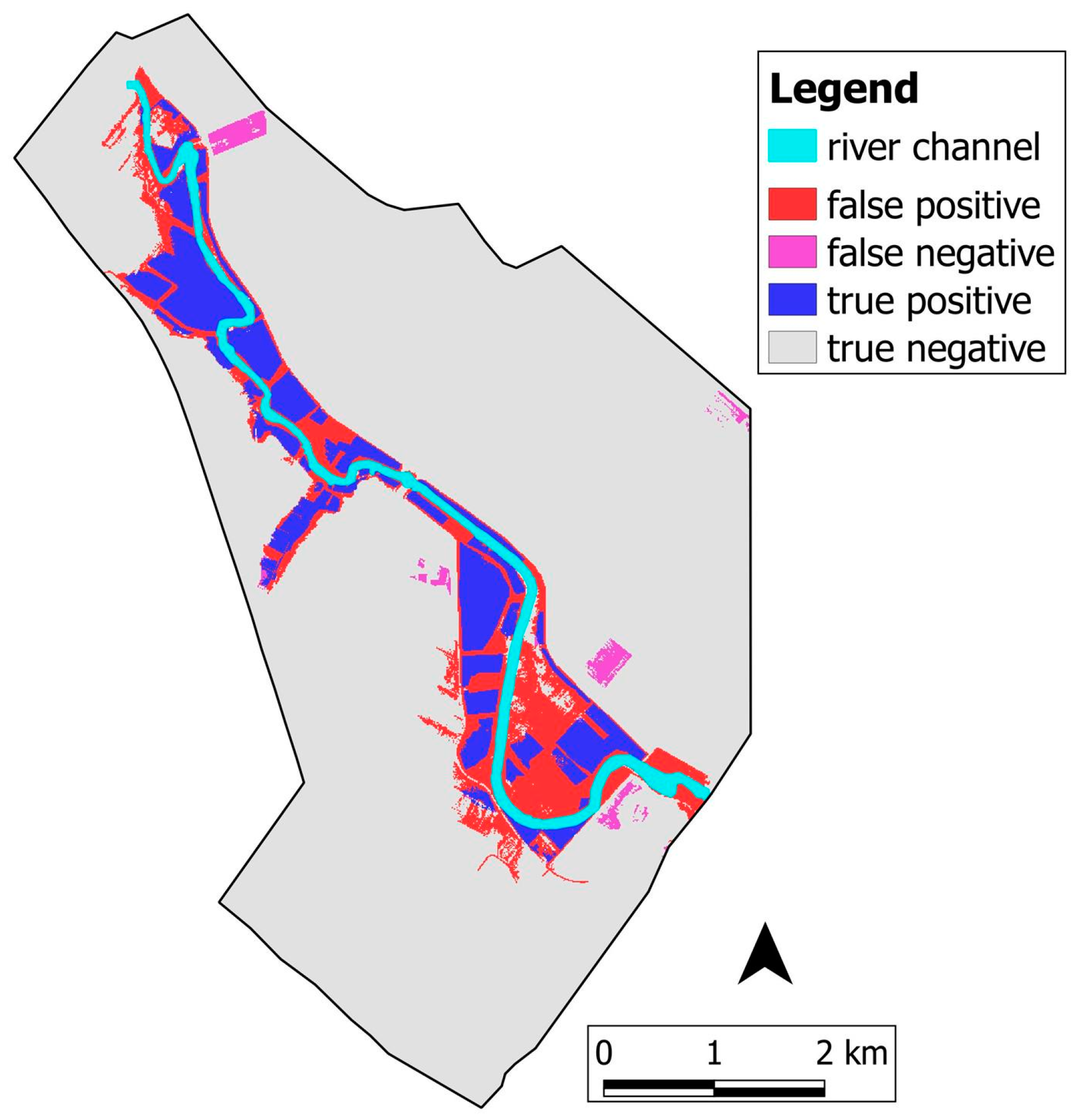
When comparing each SAR-derived map pixel to pixel with the flood map obtained with the hydraulic model at the same time step, there were four possible conditions in each map point/cell: (i) if the hydraulic model detected a flooded area when this condition was present in the SAR-derived flood map, the point was counted as a true positive; otherwise; (ii) if it identified a point as non-flooded (negative), it was counted as a false negative; (iii) if the site was defined non-flooded by the SAR map and classified as negative, it was counted as a true negative; otherwise, (iv) if it was classified as positive, it was counted as a false positive. From this, the true positive rate (also called hit rate) was estimated as:
The false positive rate (also called false alarm rate) was:
The proposed contingent matrix is similar to a confusion matrix and is successfully and widely used in the field of flood susceptibility assessment, e.g., in [
18,
47,
57,
58,
59].
Moreover, the performance measurement, used to give a deterministic indication on how well each FLORA-2D-simulated flood map represented the SAR-derived flood extent map was obtained by minimizing the sum
in the different time instants that were considered, of the false positive rate, i.e., error type 1, and the false negative rate, i.e., error type 2, assigning equal weights to the two rates. The sum of the two errors represents an objective function that can be used for calibration purposes ([
47,
58]), hereafter called minimized sum of errors (
MSE).
The outcomes of the performance measurement evaluated through the comparison between a SAR-derived flood map and the flood map obtained by the hydraulic model at the same time step, were used in the following equation to identify the hydraulic model run concordance and discordance with respect to SAR-derived flood maps:
where
is the
MSE value obtained by pixel-to-pixel comparison of each FLORA-2D-simulated flood extent map computed with a roughness coefficient of
cj and the SAR-derived map for a CSK revisit time of
ti;
is the minimum value of all the
MSE values, at the same
ti temporal instant, associated to all FLORA-2D-simulation runs characterized by different values of the
cj Manning coefficient. The equation outcome (Equation (3)) was used to judge the performance of the hydraulic model runs.
In the second step, the remotely sensed water levels were integrated to enhance the hydraulic model calibration. We compared the water depth maps of the concordance model run sets selected in the first step with floodwater depth extracted, as described in
Section 3.2, by combining SAR images and the Digital Elevation Model. Floodwater depth maps were compared pixel to pixel to see if there was concordance or discordance between the two paired maps, i.e., the SAR- and DEM-derived map and the water depth map simulated by the hydraulic model, using root square mean errors (
RSME) and the Nash and Sutcliffe efficiency coefficient (
NSE), whose formulation is shown below for measuring proper fit [
60].
where
and
represent the predicted (simulated by the hydraulic model) and observed SAR values, respectively, and
is the mean of the observed value. The resulting best performance of Manning roughness parameters that were obtained during this calibration process were then used for model validation purposes for the 2–3 December 2013 Bradano flood event scenario to evaluate calibrated model robustness under different operating conditions.


 ,
, 


