Spoofing Detection of Civilian UAVs Using Visual Odometry
Abstract
1. Introduction
2. Vision-Based UAV Spoofing Detection
2.1. Trajectory Extraction Using VO
2.2. Coordinate Transformation
2.3. Comparison of Camera and GPS Sub-Trajectories
2.3.1. Direct Comparison
2.3.2. Indirect Comparison
2.4. Vision-Based UAV Detection
- Step 1:
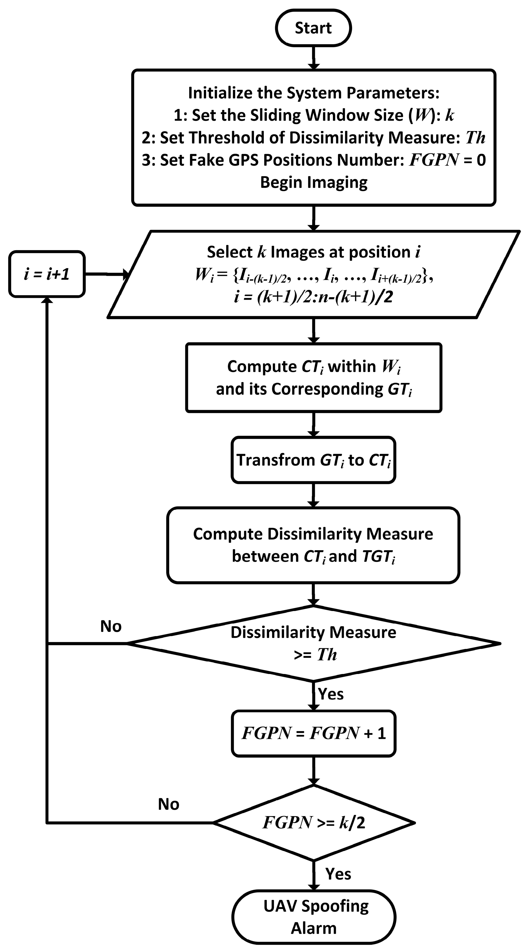
- Initially, the size of moving window (k), the threshold of the used dissimilarity measure (Th), and the threshold of UAV spoofing declaration (k/2) are determined. The threshold of dissimilarity measure is used in the determination of fake GPS positions and the threshold of UAV spoofing declaration is used in declaring of UAV spoofing. The threshold values of SEDCP, HOD_AD and HOD_TD dissimilarity measure are obtained by a sensitivity analysis that is fully described in Section 3.7. Additionally, the threshold of UAV spoofing declaration is set to k/2.
- Step 2:
- In this step, at each i-th UAV position, k images from UAV flight path, from the image number of i-(k-1)/2 to i+(k-1)/2, are selected using a moving window of Wi.
- Step 3:
- In step 3, using the selected images and their corresponding GPS positions within the window Wi, two corresponding CTi and GTi sub-trajectories are calculated.
- Step 4:
- In this step, the coordinate system of GTi is transformed into the coordinate system of CTi.
- Step 5:
- Here, the dissimilarity measure between CTi and TGTi is computed.
- Step 6:
- In this stage, the computed dissimilarity measure between CTi and TGTi within the window Wi is compared with the threshold value, Th. If the value of dissimilarity measure exceeds Th, the GPS position at point i, will be recognized as a fake position.
- Step 7:
- Finally, based on the results of the previous step, the decision is made to declare the UAV spoofing based on the given threshold.
3. Experiments and Results
3.1. Data
3.2. GPS Spoofing Simulation
3.3. UAV Spoofing Detection: First Scenario
Results of the First Scenario
3.4. UAV Spoofing Detection: Second Scenario
3.5. UAV Spoofing Detection: Third Scenario
3.6. UAV Spoofing Detection: Fourth Scenario
3.7. Sensitivity Analysis
4. Conclusions
Author Contributions
Funding
Conflicts of Interest
References
- Leick, A.; Rapoport, L.; Tatarnikov, D. GPS Satellite Surveying; John Wiley & Sons: Hoboken, NJ, USA, 2015. [Google Scholar]
- Austin, R. Unmanned Aircraft Systems: UAVS Design, Development and Deployment; John Wiley & Sons: Hoboken, NJ, USA, 2011; Volume 54. [Google Scholar]
- Elkaim, G.H.; Lie, F.A.P.; Gebre-Egziabher, D. Principles of Guidance, Navigation, and Control of UAVs. In Handbook of Unmanned Aerial Vehicles; Valavanis, K.P., Vachtsevanos, G.J., Eds.; Springer: Dordrecht, The Netherlands, 2015; pp. 347–380. [Google Scholar] [CrossRef]
- Carroll, J.V. Vulnerability Assessment of the U.S. Transportation Infrastructure that Relies on the Global Positioning System. J. Navig. 2003, 56, 185–193. [Google Scholar] [CrossRef]
- Jafarnia-Jahromi, A.; Broumandan, A.; Nielsen, J.; Lachapelle, G. GPS Vulnerability to Spoofing Threats and a Review of Antispoofing Techniques. Int. J. Navig. Obs. 2012, 2012, 16. [Google Scholar] [CrossRef]
- Dovis, F. GNSS Interference Threats and Countermeasures; Artech House: Norwood, MA, USA, 2015. [Google Scholar]
- Schmidt, G.T. Navigation sensors and systems in GNSS degraded and denied environments. Chin. J. Aeronaut. 2015, 28, 1–10. [Google Scholar] [CrossRef]
- Manfredini, E.G.; Akos, D.M.; Chen, Y.-H.; Lo, S.; Walter, T.; Enge, P. Effective GPS Spoofing Detection Utilizing Metrics from Commercial Receivers. In Proceedings of the 2018 International Technical Meeting of The Institute of Navigation, Reston, VA, USA, 29 January–1 February 2018. [Google Scholar]
- Kaplan, E.D.; Hegarty, C. Understanding GPS/GNSS: Principles and Applications; Artech House: Norwood, MA, USA, 2017. [Google Scholar]
- Kerns, A.J.; Shepard, D.P.; Bhatti, J.A.; Humphreys, T.E. Unmanned Aircraft Capture and Control Via GPS Spoofing. J. Field Robot. 2014, 31, 617–636. [Google Scholar] [CrossRef]
- Shepard, D.P.; Bhatti, J.A.; Humphreys, T.E.; Fansler, A.A. Evaluation of smart grid and civilian UAV vulnerability to GPS spoofing attacks. In Radionavigation Laboratory Conference Proceedings; The University of Texas at Austin: Austin, TX, USA, 2012. [Google Scholar]
- Horton, E.; Ranganathan, P. Development of a GPS spoofing apparatus to attack a DJI Matrice 100 Quadcopter. J. Glob. Position. Syst. 2018, 16, 9. [Google Scholar] [CrossRef]
- Li, M.; Kou, Y.; Xu, Y.; Liu, Y. Design and Field Test of a GPS Spoofer for UAV Trajectory Manipulation. In China Satellite Navigation Conference (CSNC) 2018 Proceedings; Springer: Singapore, 2018; pp. 161–173. [Google Scholar]
- He, D.; Qiao, Y.; Chen, S.; Du, X.; Chen, W.; Zhu, S.; Guizani, M. A Friendly and Low-Cost Technique for Capturing Non-Cooperative Civilian Unmanned Aerial Vehicles. IEEE Netw. 2019, 33, 146–151. [Google Scholar] [CrossRef]
- Huang, L.; Yang, Q. Low-Cost GPS Simulator GPS Spoofing by SDR. DEFCON 23 2015. [Google Scholar]
- Guo, Y.; Wu, M.; Tang, K.; Tie, J.; Li, X. Covert Spoofing Algorithm of UAV based on GPS/INS Integrated Navigation. IEEE Trans. Veh. Technol. 2019. [Google Scholar] [CrossRef]
- Broumandan, A.; Jafarnia-Jahromi, A.; Daneshmand, S.; Lachapelle, G. Overview of Spatial Processing Approaches for GNSS Structural Interference Detection and Mitigation. Proc. IEEE 2016, 104, 1246–1257. [Google Scholar] [CrossRef]
- Milaat, F.A.; Liu, H. Decentralized Detection of GPS Spoofing in Vehicular Ad Hoc Networks. IEEE Commun. Lett. 2018, 22, 1256–1259. [Google Scholar] [CrossRef]
- Sun, C.; Cheong, J.W.; Dempster, A.G.; Zhao, H.; Demicheli, L.; Feng, W. A New Signal Quality Monitoring Method for Anti-spoofing. In China Satellite Navigation Conference (CSNC) 2018 Proceedings; Springer: Singapore, 2018; pp. 221–231. [Google Scholar]
- Humphreys, T.; Bhatti, J.; Ledvina, B. The GPS Assimilator: A method for upgrading existing GPS user equipment to improve accuracy, robustness, and resistance to spoofing. In Radionavigation Laboratory Conference Proceedings, Proceedings of the ION GNSS Conference, Portland, OR, USA, 21–24 September 2010; The University of Texas at Austin: Austin, TX, USA, 2010. [Google Scholar]
- Humphreys, T.E.; Ledvina, B.M.; Psiaki, M.L.; O’Hanlon, B.W.; Kintner, P.M. Assessing the spoofing threat: Development of a portable GPS civilian spoofer. In Radionavigation Laboratory Conference Proceedings; The University of Texas at Austin: Austin, TX, USA, 2010. [Google Scholar]
- Khanafseh, S.; Roshan, N.; Langel, S.; Chan, F.; Joerger, M.; Pervan, B. GPS spoofing detection using RAIM with INS coupling. In Proceedings of the 2014 IEEE/ION Position, Location and Navigation Symposium-PLANS 2014, Monterey, CA, USA, 5–8 May 2014; pp. 1232–1239. [Google Scholar]
- White, N.A.; Maybeck, P.S.; DeVilbiss, S.L. Detection of interference/jamming and spoofing in a DGPS-aided inertial system. IEEE Trans. Aerosp. Electron. Syst. 1998, 34, 1208–1217. [Google Scholar] [CrossRef]
- Lo, S.; De Lorenzo, D.; Enge, P.; Akos, D.; Bradley, P. Signal authentication: A secure civil GNSS for today. Inside GNSS 2009, 4, 30–39. [Google Scholar]
- Psiaki, M.; Powell, S.; O’Hanlon, B. GNSS spoofing detection: Correlating carrier phase with rapid antenna motion. GPS World 2013, 24, 53–58. [Google Scholar]
- Pini, M.; Motella, B.; Gamba, M.T. Detection of correlation distortions through application of statistical methods. In Proceedings of the 26th International Technical Meeting of the Satellite Division of the Institute of Navigation (ION GNSS+ 2013), Nashville, TN, USA, 16–20 September 2013; pp. 3279–3289. [Google Scholar]
- Schmidt, D.; Radke, K.; Camtepe, S.; Foo, E.; Ren, M. A Survey and Analysis of the GNSS Spoofing Threat and Countermeasures. ACM Comput. Surv. 2016, 48, 1–31. [Google Scholar] [CrossRef]
- Jansen, K.; Pöpper, C. Advancing attacker models of satellite-based localization systems: The case of multi-device attackers. In Proceedings of the 10th ACM Conference on Security and Privacy in Wireless and Mobile Networks, Boston, MA, USA, 18–20 July 2017; pp. 156–159. [Google Scholar]
- Tippenhauer, N.O.; Pöpper, C.; Rasmussen, K.B.; Capkun, S. On the requirements for successful GPS spoofing attacks. In Proceedings of the 18th ACM Conference on Computer and Communications Security, Chicago, IL, USA, 17–21 October 2011; pp. 75–86. [Google Scholar]
- Meng, Q.; Hsu, L.-T.; Xu, B.; Luo, X.; El-Mowafy, A. A GPS Spoofing Generator Using an Open Sourced Vector Tracking-Based Receiver. Sensors 2019, 19, 3993. [Google Scholar] [CrossRef] [PubMed]
- Broumandan, A.; Lachapelle, G. Spoofing Detection Using GNSS/INS/Odometer Coupling for Vehicular Navigation. Sensors 2018, 18, 1305. [Google Scholar] [CrossRef]
- Oligeri, G.; Sciancalepore, S.; Ibrahim, O.A.; Pietro, R.D. Drive me not: GPS spoofing detection via cellular network: (architectures, models, and experiments). In Proceedings of the 12th Conference on Security and Privacy in Wireless and Mobile Networks, Miami, FL, USA, 14–17 May 2019; pp. 12–22. [Google Scholar]
- Qiao, Y.; Zhang, Y.; Du, X. A Vision-Based GPS-Spoofing Detection Method for Small UAVs. In Proceedings of the 2017 13th International Conference on Computational Intelligence and Security (CIS), Hong Kong, China, 15–18 December 2017; pp. 312–316. [Google Scholar]
- Weiss, S.; Achtelik, M.W.; Lynen, S.; Achtelik, M.C.; Kneip, L.; Chli, M.; Siegwart, R. Monocular Vision for Long-term Micro Aerial Vehicle State Estimation: A Compendium. J. Field Robot. 2013, 30, 803–831. [Google Scholar] [CrossRef]
- Chowdhary, G.; Johnson, E.N.; Magree, D.; Wu, A.; Shein, A. GPS-denied indoor and outdoor monocular vision aided navigation and control of unmanned aircraft. J. Field Robot. 2013, 30, 415–438. [Google Scholar] [CrossRef]
- Nister, D.; Naroditsky, O.; Bergen, J. Visual odometry. In Proceedings of the 2004 IEEE Computer Society Conference on Computer Vision and Pattern Recognition (CVPR 2004), Washington, DC, USA, 27 June–2 July 2004; Volume 651, pp. I-652–I-659. [Google Scholar]
- Huang, A.S.; Bachrach, A.; Henry, P.; Krainin, M.; Maturana, D.; Fox, D.; Roy, N. Visual Odometry and Mapping for Autonomous Flight Using an RGB-D Camera. In Robotics Research: The 15th International Symposium ISRR; Christensen, H.I., Khatib, O., Eds.; Springer: Cham, Switzerland, 2017; pp. 235–252. [Google Scholar]
- Andert, F.; Lorenz, S.; Mejias, L.; Bratanov, D. Radar-aided optical navigation for long and large-scale flights over unknown and non-flat terrain. In Proceedings of the 2016 International Conference on Unmanned Aircraft Systems (ICUAS), Arlington, VA, USA, 7–10 June 2016; pp. 465–474. [Google Scholar]
- Ghazali, K.H.; Jadin, M.S.; Jie, M.; Xiao, R. Novel automatic eye detection and tracking algorithm. Opt. Lasers Eng. 2015, 67, 49–56. [Google Scholar] [CrossRef]
- Lucas, B.D.; Kanade, T. An iterative image registration technique with an application to stereo vision. In Proceedings of the 7th International Joint Conference on Artificial Intelligence, Vancouver, BC, Canada, 24–28 August 1981. [Google Scholar]
- Fraundorfer, F.; Scaramuzza, D. Visual Odometry: Part II: Matching, Robustness, Optimization, and Applications. IEEE Robot. Autom. Mag. 2012, 19, 78–90. [Google Scholar] [CrossRef]
- Cadena, C.; Carlone, L.; Carrillo, H.; Latif, Y.; Scaramuzza, D.; Neira, J.; Reid, I.; Leonard, J.J. Past, Present, and Future of Simultaneous Localization and Mapping: Toward the Robust-Perception Age. IEEE Trans. Robot. 2016, 32, 1309–1332. [Google Scholar] [CrossRef]
- Cai, Y.; Ng, R. Indexing spatio-temporal trajectories with Chebyshev polynomials. In Proceedings of the 2004 ACM SIGMOD International Conference on Management of Data, Paris, France, 13–18 June 2004; pp. 599–610. [Google Scholar]
- Scaramuzza, D.; Fraundorfer, F. Visual Odometry [Tutorial]. IEEE Robot. Autom. Mag. 2011, 18, 80–92. [Google Scholar] [CrossRef]
- Gonzalez, R.; Rodriguez, F.; Guzman, J.L.; Pradalier, C.; Siegwart, R. Combined visual odometry and visual compass for off-road mobile robots localization. Robotica 2012, 30, 865–878. [Google Scholar] [CrossRef]
- Scaramuzza, D.; Siegwart, R. Appearance-Guided Monocular Omnidirectional Visual Odometry for Outdoor Ground Vehicles. IEEE Trans. Robot. 2008, 24, 1015–1026. [Google Scholar] [CrossRef]
- Poddar, S.; Kottath, R.; Karar, V. Evolution of Visual Odometry Techniques. arXiv 2018, arXiv:1804.11142. [Google Scholar]
- Lowe, D.G. Distinctive Image Features from Scale-Invariant Keypoints. Int. J. Comput. Vis. 2004, 60, 91–110. [Google Scholar] [CrossRef]
- Milella, A.; Siegwart, R. Stereo-Based Ego-Motion Estimation Using Pixel Tracking and Iterative Closest Point. In Proceedings of the Fourth IEEE International Conference on Computer Vision Systems (ICVS’06), New York, NY, USA, 4–7 January 2006; p. 21. [Google Scholar]
- Warren, M.; Corke, P.; Upcroft, B. Long-range stereo visual odometry for extended altitude flight of unmanned aerial vehicles. Int. J. Robot. Res. 2015, 35, 381–403. [Google Scholar] [CrossRef]
- Gowayyed, M.A.; Torki, M.; Hussein, M.E.; El-Saban, M. Histogram of Oriented Displacements (HOD): Describing Trajectories of Human Joints for Action Recognition. In Proceedings of the Twenty-Third International Joint Conference on Artificial Intelligence, Beijing, China, 3–19 August 2013; pp. 1351–1357. [Google Scholar]


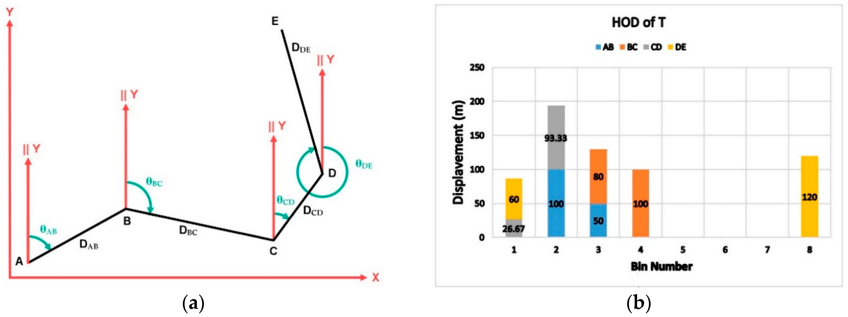
| Side | Dj,j+1 | θj,j+1 | FisrtBN | SecondBN | FirstBN Portion | SecondBN Portion |
|---|---|---|---|---|---|---|
| AB | 150 | 60 | 2 | 3 | 100 | 50 |
| BC | 180 | 115 | 3 | 4 | 80 | 100 |
| CD | 120 | 35 | 1 | 2 | 26.67 | 93.33 |
| DE | 180 | 345 | 8 | 1 | 60 | 120 |
| HOD Bins | ||||||||
|---|---|---|---|---|---|---|---|---|
| Sidej,j+1 | 1 | 2 | 3 | 4 | 5 | 6 | 7 | 8 |
| AB | 0 | 100 | 50 | 0 | 0 | 0 | 0 | 0 |
| BC | 0 | 0 | 80 | 100 | 0 | 0 | 0 | 0 |
| CD | 26.67 | 93.33 | 0 | 0 | 0 | 0 | 0 | 0 |
| DE | 60 | 0 | 0 | 0 | 0 | 0 | 0 | 120 |
| HOD | 86.67 | 193.33 | 130 | 100 | 0 | 0 | 0 | 120 |
| SEDCP | HOD_AD | HOD_TD | |
|---|---|---|---|
| W = 9 | 33 (100%) | 13 (39%) | 13 (39%) |
| W = 15 | 33 (100%) | 19 (57%) | 19 (57%) |
| W = 21 | 33 (100%) | 25 (75%) | 25 (75%) |
| SEDCP | HOD_AD | HOD_TD | |
|---|---|---|---|
| W = 9 | 54 (84%) | 44 (69%) | 50 (78%) |
| W = 15 | 64 (100%) | 55 (86%) | 59 (92%) |
| W = 21 | 64 (100%) | 62 (97%) | 64 (100%) |
| SEDCP | HOD_AD | HOD_TD | |
|---|---|---|---|
| W = 9 | 31 (97%) | 12 (38%) | 11 (34%) |
| W = 15 | 31 (97%) | 26 (81%) | 29 (91%) |
| W = 21 | 32 (100%) | 27 (84%) | 29 (91%) |
| SEDCP | HOD_AD | HOD_TD | |
|---|---|---|---|
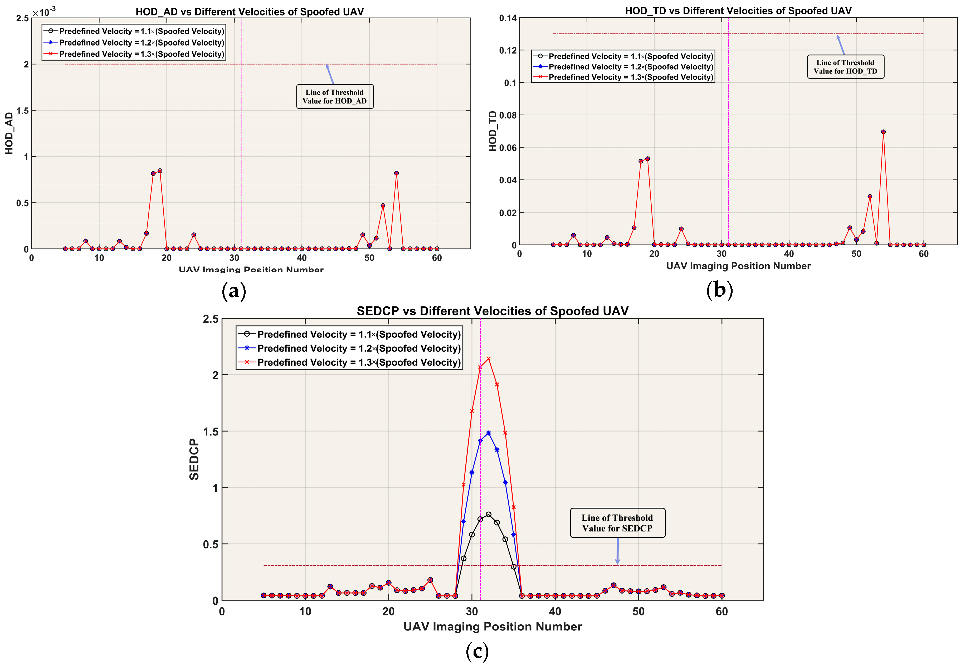
| Predefined Velocity = 1.1 × (Spoofed Velocity) | 6 (18%) | 0 (0%) | 0 (0%) |
| Predefined Velocity = 1.2 × (Spoofed Velocity) | 7 (21%) | 0 (0%) | 0 (0%) |
| Predefined Velocity = 1.3 × (Spoofed Velocity) | 7 (21%) | 0 (0%) | 0 (0%) |
© 2019 by the authors. Licensee MDPI, Basel, Switzerland. This article is an open access article distributed under the terms and conditions of the Creative Commons Attribution (CC BY) license (http://creativecommons.org/licenses/by/4.0/).
Share and Cite
Varshosaz, M.; Afary, A.; Mojaradi, B.; Saadatseresht, M.; Ghanbari Parmehr, E. Spoofing Detection of Civilian UAVs Using Visual Odometry. ISPRS Int. J. Geo-Inf. 2020, 9, 6. https://doi.org/10.3390/ijgi9010006
Varshosaz M, Afary A, Mojaradi B, Saadatseresht M, Ghanbari Parmehr E. Spoofing Detection of Civilian UAVs Using Visual Odometry. ISPRS International Journal of Geo-Information. 2020; 9(1):6. https://doi.org/10.3390/ijgi9010006
Chicago/Turabian StyleVarshosaz, Masood, Alireza Afary, Barat Mojaradi, Mohammad Saadatseresht, and Ebadat Ghanbari Parmehr. 2020. "Spoofing Detection of Civilian UAVs Using Visual Odometry" ISPRS International Journal of Geo-Information 9, no. 1: 6. https://doi.org/10.3390/ijgi9010006
APA StyleVarshosaz, M., Afary, A., Mojaradi, B., Saadatseresht, M., & Ghanbari Parmehr, E. (2020). Spoofing Detection of Civilian UAVs Using Visual Odometry. ISPRS International Journal of Geo-Information, 9(1), 6. https://doi.org/10.3390/ijgi9010006


