
Closed-Loop Optical Tracking of a Micro-Conveyor over a Smart Surface
 , , , and
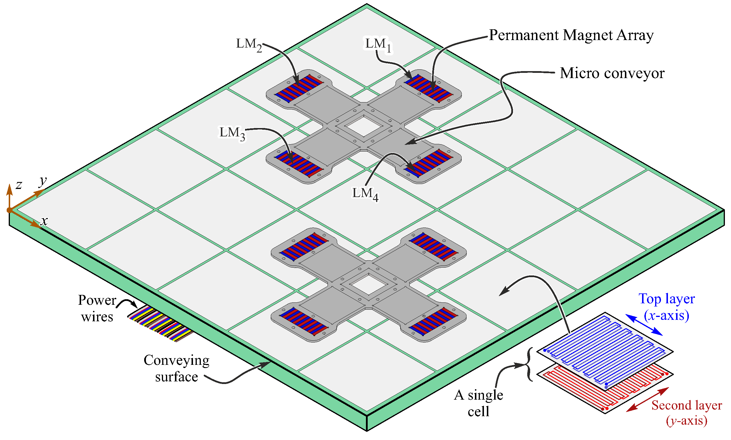
Abstract
:1. Introduction
2. System Description
2.1. Micro-Conveyor’s Design
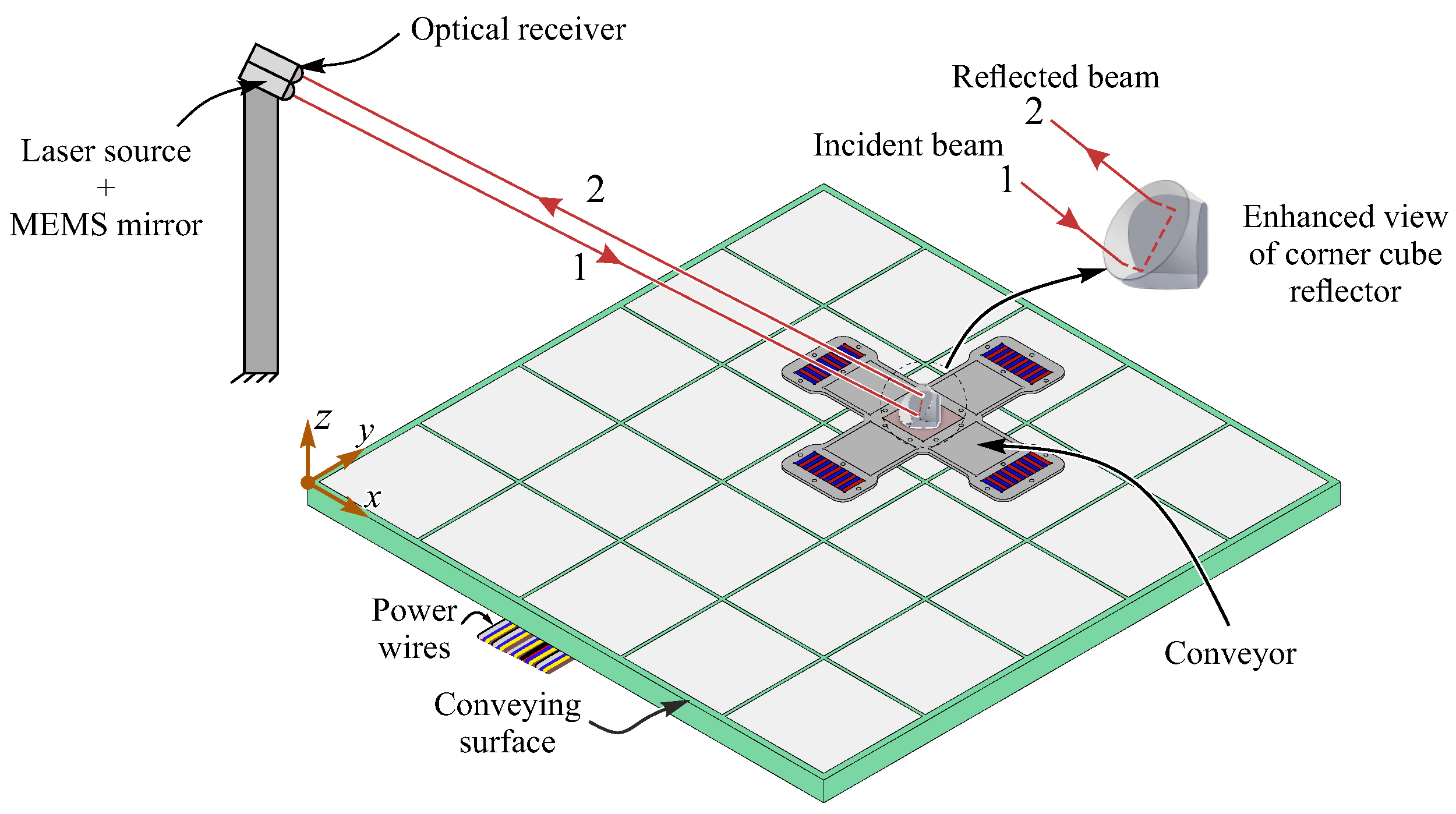
2.2. Localization and Tracking Architecture
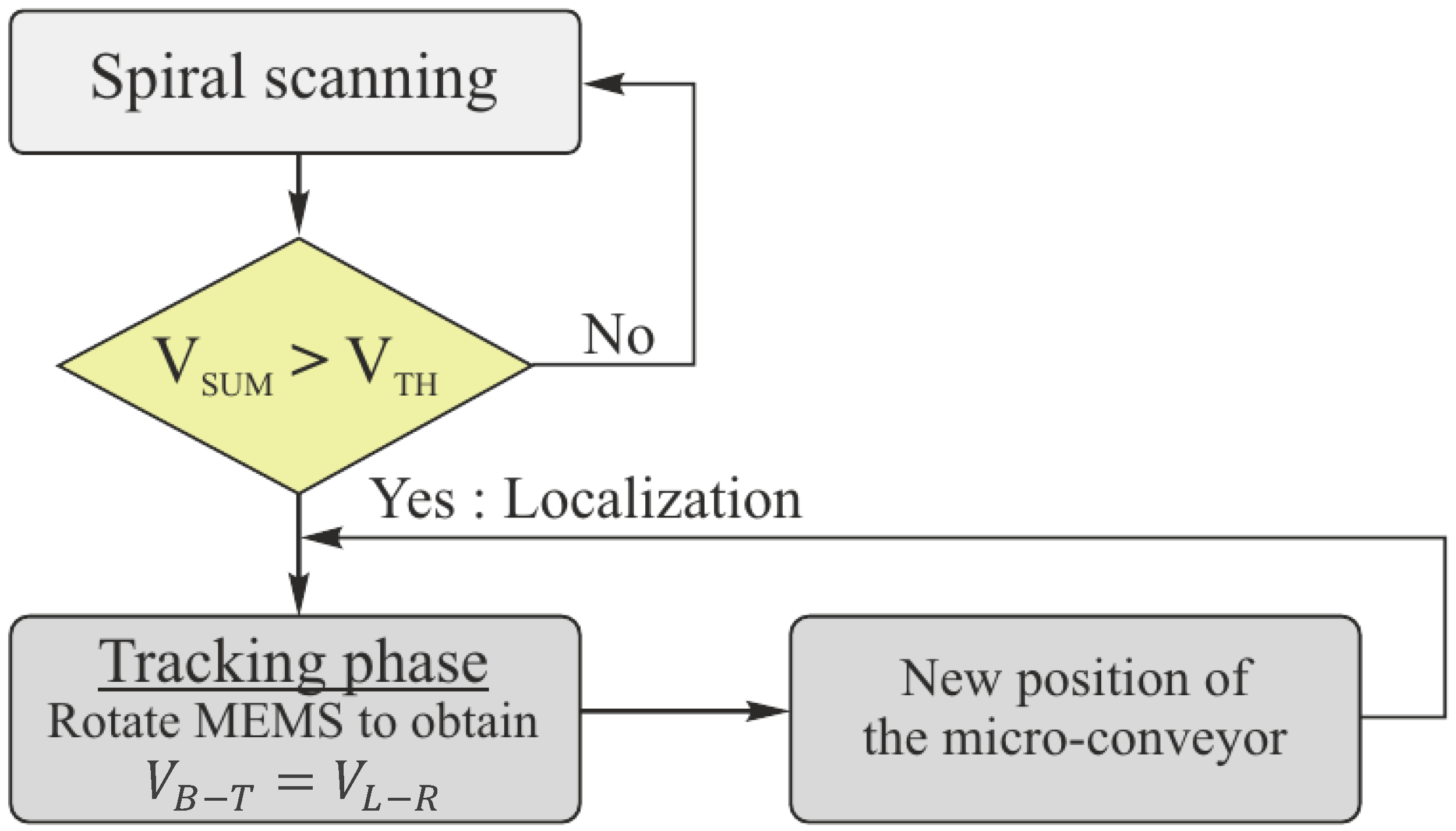
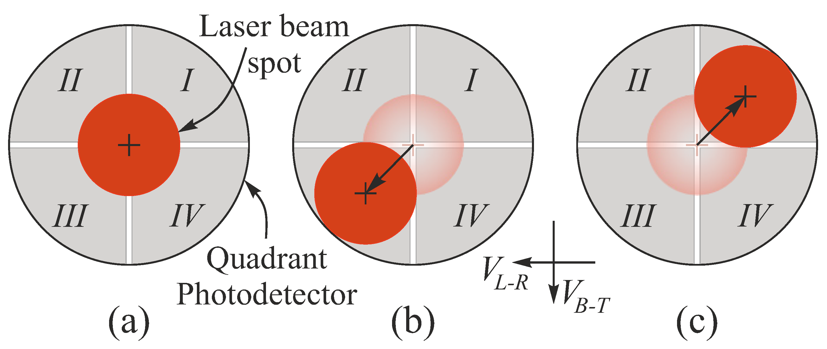
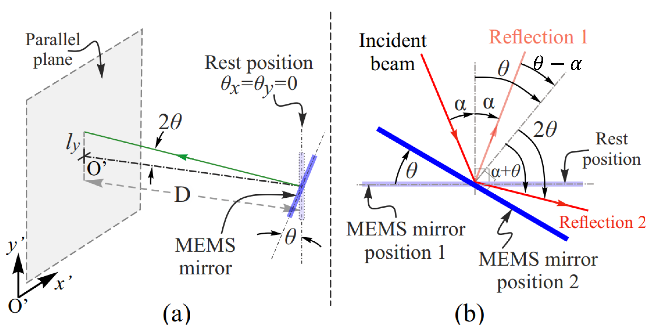
2.3. Localization and Tracking Control
3. Experimental Setup and Surface Calibration
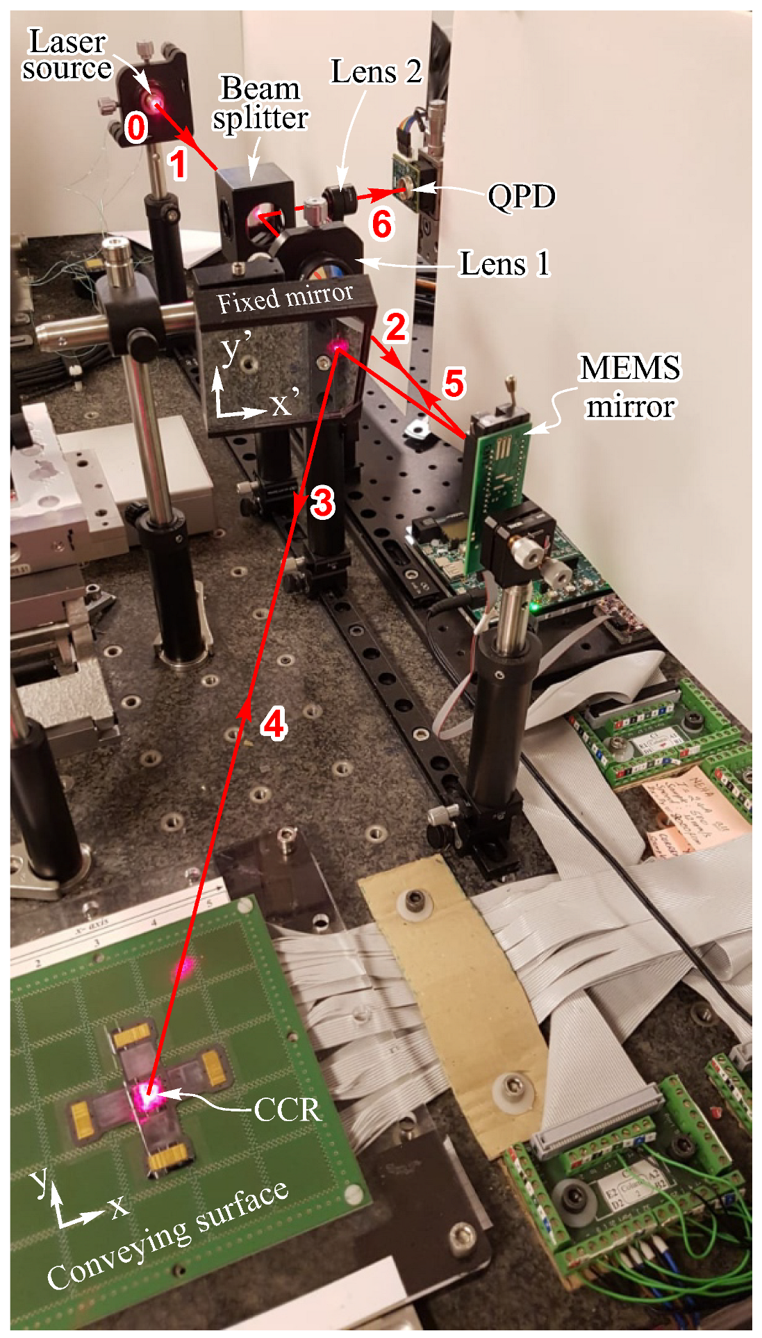
3.1. Experimental Setup
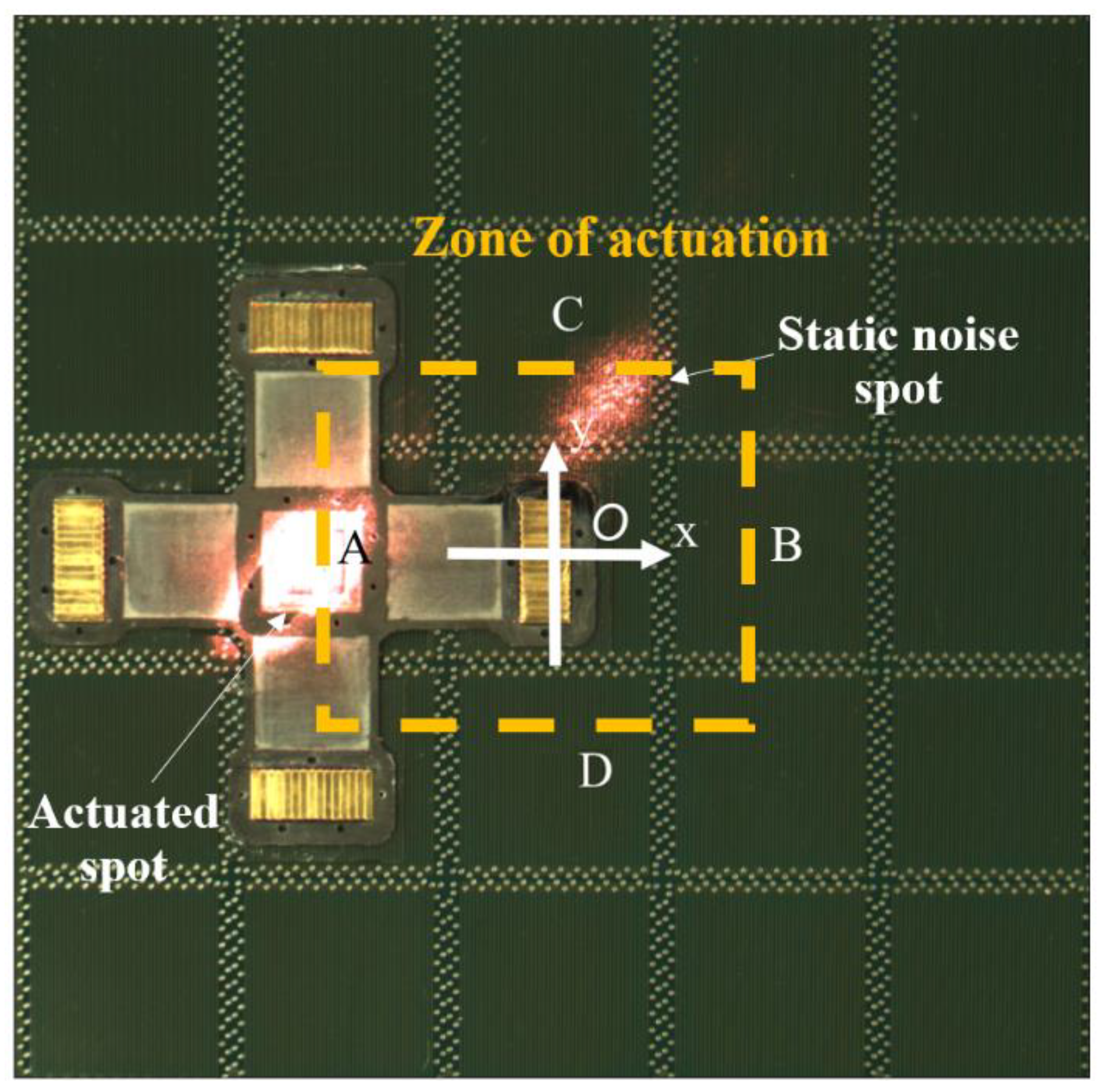
3.2. Conveying Surface Calibration
4. Closed-Loop Control of Micro-Conveyor’s Trajectory and Experimental Results
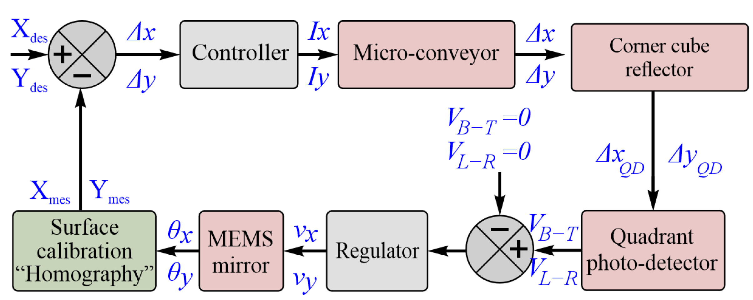
4.1. Closed Loop Control System
4.2. Experimental Results
5. Conclusions
Author Contributions
Funding
Data Availability Statement
Acknowledgments
Conflicts of Interest
Abbreviations
| CCR | Corner Cube Reflector |
| LED | Light Emitting Diodes |
| LM | Linear Motors |
| MEMS | Micro Electro Mechanical System |
| QPD | Quadrant PhotoDetector |
| RMS | Root Mean Square |
| RFID | Radio Frequency Identification |
| ToA | Time Difference of Arrival |
| TDoA | Time of Arrival |
| UWB | Ultra Wide Band |
References
- Diederichs, C.; Mikczinski, M.; Tiemerding, T. A Flexible and Compact High Precision Micro-Factory for Low Volume Production and Lab-Automation. In Proceedings of the ISR/Robotik 2014; 41st International Symposium on Robotics, Munich, Germany, 2–3 June 2014; pp. 1–7. [Google Scholar]
- Zhakypov, Z.; Uzunovic, T.; Nergiz, A.O.; Baran, E.A.; Golubovic, E.; Sabanovic, A. Modular and reconfigurable desktop microfactory for high precision manufacturing. Int. J. Adv. Manuf. Technol. 2017, 90, 3749–3759. [Google Scholar] [CrossRef]
- Yang, T.; Cabani, A.; Chafouk, H. A survey of recent indoor localization scenarios and methodologies. Sensors 2021, 21, 8086. [Google Scholar] [CrossRef]
- Zhao, Y.; Patwari, N. An experimental comparison of radio transceiver and transceiver-free localization methods. J. Sens. Actuator Netw. 2016, 5, 13. [Google Scholar] [CrossRef]
- Magsino, E.; Barrameda, J.M.C.; Puno, A.; Ong, S.; Siapco, C.; Vibal, J. Determining Commercial Parking Vacancies Employing Multiple WiFiRSSI Fingerprinting Method. J. Sens. Actuator Netw. 2023, 12, 22. [Google Scholar] [CrossRef]
- Di Rienzo, F.; Madonna, A.; Carbonaro, N.; Tognetti, A.; Virdis, A.; Vallati, C. Short-Range Localization via Bluetooth Using Machine Learning Techniques for Industrial Production Monitoring. J. Sens. Actuator Netw. 2023, 12, 75. [Google Scholar] [CrossRef]
- Kammel, C.; Kögel, T.; Gareis, M.; Vossiek, M. A Cost-Efficient Hybrid UHF RFID and Odometry-Based Mobile Robot Self-Localization Technique With Centimeter Precision. IEEE J. Radio Freq. Identif. 2022, 6, 467–480. [Google Scholar] [CrossRef]
- Shamsfakhr, F.; Motroni, A.; Palopoli, L.; Buffi, A.; Nepa, P.; Fontanelli, D. Robot localisation using UHF-RFID tags: A Kalman smoother approach. Sensors 2021, 21, 717. [Google Scholar] [CrossRef]
- Elsanhoury, M.; Mäkelä, P.; Koljonen, J.; Välisuo, P.; Shamsuzzoha, A.; Mantere, T.; Elmusrati, M.; Kuusniemi, H. Precision positioning for smart logistics using ultra-wideband technology-based indoor navigation: A review. IEEE Access 2022, 10, 44413–44445. [Google Scholar] [CrossRef]
- Dabove, P.; Di Pietra, V.; Piras, M.; Jabbar, A.A.; Kazim, S.A. Indoor positioning using Ultra-wide band (UWB) technologies: Positioning accuracies and sensors’ performances. In Proceedings of the 2018 IEEE/ION Position, Location and Navigation Symposium (PLANS), Monterey, CA, USA, 23–26 April 2018; pp. 175–184. [Google Scholar]
- Fortes, J.; Švingál, M.; Porteleky, T.; Jurík, P.; Drutarovskỳ, M. Positioning and Tracking of Multiple Humans Moving in Small Rooms Based on a One-Transmitter–Two-Receiver UWB Radar Configuration. Sensors 2022, 22, 5228. [Google Scholar] [CrossRef]
- Meucci, M.; Seminara, M.; Tarani, F.; Riminesi, C.; Catani, J. Visible light communications through diffusive illumination of sculptures in a real museum. J. Sens. Actuator Netw. 2021, 10, 45. [Google Scholar] [CrossRef]
- Guan, W.; Huang, L.; Hussain, B.; Yue, C.P. Robust Robotic Localization Using Visible Light Positioning and Inertial Fusion. IEEE Sensors J. 2022, 22, 4882–4892. [Google Scholar] [CrossRef]
- Guan, W.; Chen, S.; Wen, S.; Tan, Z.; Song, H.; Hou, W. High-accuracy robot indoor localization scheme based on robot operating system using visible light positioning. IEEE Photonics J. 2020, 12, 7901716. [Google Scholar] [CrossRef]
- Lin, Y.; Chen, X.; Zhong, W. Positioning of planar objects on an air film using a viscous traction principle. In Proceedings of the 2019 IEEE 8th International Conference on Fluid Power and Mechatronics (FPM), Wuhan, China, 10–13 April 2019; pp. 50–59. [Google Scholar] [CrossRef]
- ZarroukT, A.; Belharet, K.; TahriT, O. Vision-based magnetic platform for actuator positioning and wireless control of microrobots. In Proceedings of the 2019 IEEE/RSJ International Conference on Intelligent Robots and Systems (IROS), Macau, China, 3–8 November 2019; pp. 1601–1606. [Google Scholar] [CrossRef]
- Zhang, J.; Dai, X.; Wu, W.; Du, K. Micro-Vision Based High-Precision Space Assembly Approach for Trans-Scale Micro-Device: The CFTA Example. Sensors 2023, 23, 450. [Google Scholar] [CrossRef] [PubMed]
- Chen, Y.; Li, H.; Zhu, Z.; Zhao, C. A Method for Achieving Nanoscale Visual Positioning Measurement Based on Ultra-Precision Machining Microstructures. Micromachines 2023, 14, 1444. [Google Scholar] [CrossRef] [PubMed]
- Guelpa, V.; Sandoz, P.; Vergara, M.A.; Clévy, C.; Le Fort-Piat, N.; Laurent, G.J. 2D visual micro-position measurement based on intertwined twin-scale patterns. Sensors Actuators A Phys. 2016, 248, 272–280. [Google Scholar] [CrossRef]
- Chavitranuruk, N.; Pengwang, E. Vision System for Detecting and Locating Micro-Scale Objects with Guided Cartesian Robot. In Proceedings of the 2023 8th Asia-Pacific Conference on Intelligent Robot Systems (ACIRS), Xi’an, China, 7–9 July 2023; pp. 12–18. [Google Scholar]
- Hussein, Z.; Banimelhem, O. Energy-Efficient Relay Tracking and Predicting Movement Patterns with Multiple Mobile Camera Sensors. J. Sens. Actuator Netw. 2023, 12, 35. [Google Scholar] [CrossRef]
- Tripicchio, P.; D’Avella, S.; Camacho-Gonzalez, G.; Landolfi, L.; Baris, G.; Avizzano, C.A.; Filippeschi, A. Multi-camera extrinsic calibration for real-time tracking in large outdoor environments. J. Sens. Actuator Netw. 2022, 11, 40. [Google Scholar] [CrossRef]
- Mabed, H.; Dedu, E. Short and long term optimization for micro-object conveying with air-jet modular distributed system. J. Parallel Distrib. Comput. 2020, 144, 98–108. [Google Scholar] [CrossRef]
- Chen, X.; Zhong, W.; Li, C.; Fang, J.; Liu, F. Development of a contactless air conveyor system for transporting and positioning planar objects. Micromachines 2018, 9, 487. [Google Scholar] [CrossRef]
- Kojima, M.; Yoshimoto, S.; Yamamoto, A. Slider Sheet Detection in Charge-Induction Electrostatic Film Actuators. Sensors 2023, 23, 1529. [Google Scholar] [CrossRef]
- Qu, Y.; Wang, P.; Wang, W.; Wang, H. Analyses and Optimization of Electrostatic Film Actuators Considering Electrical Breakdown. IEEE Robot. Autom. Lett. 2021, 6, 1152–1159. [Google Scholar] [CrossRef]
- Li, X.; Wang, S.; Peng, X.; Xu, G.; Dong, J.; Tian, F.; Zhang, Q. The Frequency-Variable Rotor-Blade-Based Two-Degree-of-Freedom Actuation Principle for Linear and Rotary Motion. Sensors 2023, 23, 8314. [Google Scholar] [CrossRef]
- Yuan, X.; Liu, Y.; Zou, H.; Ji, J.; Zhou, T.; Wang, W. Design and Analysis of a 2-D Piezoelectric Platform Based on Three-Stage Amplification and L-Shaped Guiding. IEEE Trans. Instrum. Meas. 2022, 71, 7505712. [Google Scholar] [CrossRef]
- Bosch-Mauchand, M.; Arora, N.; Prelle, C.; Daaboul, J. Electromagnetic modular Smart Surface architecture and control in a microfactory context. Comput. Ind. 2016, 81, 152–170. [Google Scholar]
- Salem, M.B.; Petit, L.; Khan, M.U.; Terrien, J.; Prelle, C.; Lamarque, F.; Coradin, T.; Egles, C. A Miniature Tubular Linear Electromagnetic Actuator: Design, Modeling and Experimental Validation. In Proceedings of the 2022 International Conference on Manipulation, Automation and Robotics at Small Scales (MARSS), Toronto, ON, Canada, 25–29 July 2022; pp. 1–5. [Google Scholar] [CrossRef]
- Malak, S.; Al Hajjar, H.; Dupont, E.; Khan, M.U.; Prelle, C.; Lamarque, F. Optical Localization and Tracking Method of a Mobile Micro-Conveyor Over a Smart Surface. IEEE Sensors J. 2021, 21, 10618–10627. [Google Scholar] [CrossRef]
- Xu, Q. Design and development of a compact flexure-based XY precision positioning system with centimeter range. IEEE Trans. Ind. Electron. 2013, 61, 893–903. [Google Scholar] [CrossRef]
- Deng, J.; Liu, Y.; Li, K.; Zhang, S. Design, Modeling, and Experimental Evaluation of a Compact Piezoelectric XY Platform for Large Travel Range. IEEE Trans. Ultrason. Ferroelectr. Freq. Control 2020, 67, 863–872. [Google Scholar] [CrossRef] [PubMed]
- Deng, J.; Liu, Y.; Liu, J.; Xu, D.; Wang, Y. Development of a planar piezoelectric actuator using bending–bending hybrid transducers. IEEE Trans. Ind. Electron. 2018, 66, 6141–6149. [Google Scholar] [CrossRef]
- Liu, Y.; Deng, J.; Su, Q. Review on Multi-Degree-of-Freedom Piezoelectric Motion Stage. IEEE Access 2018, 6, 59986–60004. [Google Scholar] [CrossRef]
- The UTC Roberval Laboratory. Available online: https://www.utc.fr/en/research/utc-research-units/mechanics-energy-and-electricity-roberval/ (accessed on 1 March 2024).
- Arora, N.; Khan, M.U.; Petit, L.; Lamarque, F.; Prelle, C. Design and development of a planar electromagnetic conveyor for the microfactory. IEEE/ASME Trans. Mechatron. 2019, 24, 1723–1731. [Google Scholar] [CrossRef]
- Khan, M.U.; Prelle, C.; Lamarque, F.; Büttgenbach, S. Design and Assessment of a Micropositioning System Driven by Electromagnetic Actuators. IEEE/ASME Trans. Mechatron. 2017, 22, 551–560. [Google Scholar] [CrossRef]
- Milanovic, V. Linearized gimbal-less two-axis MEMS mirrors. In Proceedings of the Optical Fiber Communication Conference, San Diego, CA, USA, 22–26 March 2009; p. JThA19. [Google Scholar]
- MEMS Driver 5.X User Guide. 2017. Available online: http://mirrorcletech.com/hva.html (accessed on 1 April 2024).
- Quad Sum and Difference Amplifier-Part Description QP50-6SD2. Available online: https://www.first-sensor.com/cms/upload/datasheets/QP50-6-42u_SD2_5000010.pdf (accessed on 10 April 2024).
- Yang, C.; Lu, W.; Xia, Y. Positioning accuracy analysis of industrial robots based on non-probabilistic time-dependent reliability. IEEE Trans. Reliab. 2023, 73, 608–621. [Google Scholar] [CrossRef]
- Yang, C.; Xia, Y. Interval Pareto front-based multi-objective robust optimization for sensor placement in structural modal identification. Reliab. Eng. Syst. Saf. 2024, 242, 109703. [Google Scholar] [CrossRef]
- Yang, C.; Xia, Y. A novel two-step strategy of non-probabilistic multi-objective optimization for load-dependent sensor placement with interval uncertainties. Mech. Syst. Signal Process. 2022, 176, 109173. [Google Scholar] [CrossRef]


Disclaimer/Publisher’s Note: The statements, opinions and data contained in all publications are solely those of the individual author(s) and contributor(s) and not of MDPI and/or the editor(s). MDPI and/or the editor(s) disclaim responsibility for any injury to people or property resulting from any ideas, methods, instructions or products referred to in the content. |
© 2024 by the authors. Licensee MDPI, Basel, Switzerland. This article is an open access article distributed under the terms and conditions of the Creative Commons Attribution (CC BY) license (https://creativecommons.org/licenses/by/4.0/).
Share and Cite
Malak, S.; Hajjar, H.A.; Dupont, E.; Khan, M.-U.; Prelle, C.; Lamarque, F. Closed-Loop Optical Tracking of a Micro-Conveyor over a Smart Surface. J. Sens. Actuator Netw. 2024, 13, 27. https://doi.org/10.3390/jsan13020027
Malak S, Hajjar HA, Dupont E, Khan M-U, Prelle C, Lamarque F. Closed-Loop Optical Tracking of a Micro-Conveyor over a Smart Surface. Journal of Sensor and Actuator Networks. 2024; 13(2):27. https://doi.org/10.3390/jsan13020027
Chicago/Turabian StyleMalak, Saly, Hani Al Hajjar, Erwan Dupont, Muneeb-Ullah Khan, Christine Prelle, and Frederic Lamarque. 2024. "Closed-Loop Optical Tracking of a Micro-Conveyor over a Smart Surface" Journal of Sensor and Actuator Networks 13, no. 2: 27. https://doi.org/10.3390/jsan13020027