Abstract
An unsteady numerical simulation method was used in order to explore more efficient atomization methods for liquid fuel in scramjet combustors and to study the influence of different shock wave incident positions on the atomization characteristics of kerosene in crossflow. The wedge compression surface was used to generate the incident shock wave, and the incident position of the shock wave on the fuel jet was controlled by changing the angle of the wedge surface. The inlet Mach number was 2.01; the total temperature was 300 K, and the momentum ratio was 12. The research results show that as the incident position of the shock wave moves upstream, the penetration depth of the jet is essentially unchanged, but the inner edge trajectory of the jet is closer to the wall. Because the shock wave affects the Kelvin–Helmholtz instability of the jet, the unsteadiness of the jet root is strengthened, and the unsteadiness downstream of the jet is weakened. The atomization of the jet and the stability of the particle-size distribution are, thus, realized more quickly. The incident shock wave reduces the Sauter mean diameter of the jet section and makes the droplet distribution more uniform. The incident shock wave makes the atomization angle of the jet along the flow direction increase first and then decrease. The changes in the jet characteristics are determined by the changes in the reflux region, momentum transport, and pressure distribution caused by the incident shock wave.
1. Introduction
The scramjet has become the preferred form of propulsion system for high-speed aircrafts because of its excellent performance at high flight Mach number, and it has become the focus of research in the aerospace field [1]. For scramjets, the speed of the incoming flow is fast, and the residence time of the fuel is on the order of milliseconds. Therefore, it is one of the key technologies in achieving efficient fuel mixing and stable combustion within a limited time and space. From the perspective of the entire combustion process, the atomization process of fuel occupies nearly 60% of the time [2,3]. Therefore, it is very important to explore efficient fuel atomization modes to improve the performance of scramjets. Injecting fuel by transverse jets is a promising fuel atomization method.
There have been many research studies on the aerodynamic structure, breakup mechanism, and unsteady characteristics of crossflow in supersonic flow. Hidemi [4] studied the effects of injection and main flow conditions on the turbulent structure produced by a gaseous sonic transverse injection into a supersonic airstream. Rana [5,6] studied the unsteady characteristics of the jet in crossflow. It is pointed out that the Kelvin–Helmholtz (K-H) instability in the shear layer of the windward jet is the dominant factor in the mixing of the windward jet. Génin [7] pointed out that the K-H instability caused by the velocity between the jet and air would induce large-scale turbulent vortices. In summary, we have a certain understanding of the aerodynamic characteristics of the crossflow in a supersonic flow. To further increase the atomization efficiency, the effect of the incidence of shock waves is considered. The shock wave generated by the shock generator is used to enhance the mixing of the fuel and mainstream, and accelerate the fuel atomization process, which has been largely of interest because of its high efficiency. Nakamura et al. [8] took the transverse jet of hydrogen as the research object and focused on the influence of the incident shock wave on flame stability. The research results showed that flame stability would weaken or even extinguish as the incident point of the shock wave moved forward. Tahsini et al. [9] studied the impact of incident shock waves on combustion efficiency and total pressure loss, and pointed out that incident shock waves could improve combustion efficiency and increase the total pressure loss. At the same time, when the incident point of the shock wave was located upstream of the jet, the combustion efficiency was significantly higher. Shekarian et al. [10] used the physical model of incident shock generated by a wedge of 10° and the calculation model of RANS to explore the impact of incident shock position on the recirculation zone of the spray field. The results showed that different incident positions had different effects on the recirculation zone, and the incident shock changed the characteristics of the recirculation zone of the incident position. When the incident position was located downstream of the jet, it was more conducive to mixing and flame stability. Mai et al. [11] conducted a similar study by combining experimental and numerical methods, and the results showed that due to the interaction between the shock wave and jet, when the incident point was located downstream of the jet, a large-scale recirculation zone would be formed, which further enhanced the mixing and increased the residence time. Schetz [12] and Erdem et al. [13] adopted experimental research methods to further confirm that the incident point of a shock wave located downstream of the jet could effectively enhance mixing. Huang et al. [14,15] used a numerical simulation to study the influence of geometric characteristics of the shock generator (such as angle, position, size, etc.) on mixing. The results showed that the geometric characteristics of the shock generator would affect the mixing effect; the influence of the geometric characteristics on mixing was not monotonic, but there was an optimal design scheme. Gerdroodbary et al. [16] studied the coupling interference between the incident shock wave and the flow field of the transverse jet on porous walls and used shock generators of different angles to explore their influence on the mixing effect. The results showed that a large mixing efficiency was obtained downstream at 15°.
The above studies focused on the influence of an incident shock wave on combustion performance, the structural characteristics of the flow field itself, and the mixing effect. However, the influence of different incident shock waves on the characteristics of the spray in crossflow, such as penetration depth, droplet spanwise distribution, and particle size distribution, is investigated in relatively few studies. The mechanisms of related changes also need to be explored. It is very important to further understand the effect of shock waves on fuel atomization characteristics in crossflow. Therefore, this paper uses an accurate unsteady numerical simulation method to study the influence of different incident positions of a shock wave on the characteristics of the transverse jet itself, in order to provide technical support for the mixing enhancement technology under the action of an incident shock wave.
2. Numerical Simulation Method
2.1. Calculation Model
The coupled implicit solver based on pressure was used. The SST k-ω model (Shear stress transport), which combines the standard k-ω model in the near-wall region with the k-ε model in the far-field region, was used as the turbulence model. At the same time, the low Reynolds number correction was considered. This model is more accurate and reliable than results obtained by the standard k-ε model [17]. The process of atomization, evaporation, and mixing of kerosene droplets in a supersonic flow was simulated based on a discrete phase model (DPM). The governing equation was the Navier–Stokes equation of 3D mass average [18]:
In the equation, Q = [ρ, ρu, ρv, ρw, ρE, ρcs, ρk, ρω]T, where E, F, and G are inviscid fluxes, Ev, Fv, Gv are viscous fluxes, and S is the source term. The equation E = e + (u2 + v2+ w2)/2 is the total internal energy per unit mass, and cs is the mass fraction of each component. Based on the finite volume method [19], the equations were solved; the physical quantities were discretized with second-order accuracy, and the residuals of each variable were less than 10−4. The unsteady simulation time step of the flow was 5 × 10⁻⁶ s, and the unsteady method was used to track the kerosene droplets, which had a time step of 10−5 s. The equation for the motion of the droplet is [20]:
where is the droplet velocity, is the drag force per unit mass, u is the continuous phase velocity, g is the gravitational acceleration, ρ is the continuous phase density, is the droplet density, and F is the other forces. The atomization cone model was used for the spray model, and the droplet diameter distribution was a Rosin–Rammler distribution. The K-H/R-T model was used for the droplet secondary breakup model. The kerosene–air mixture was used for species transport. The density of the liquid kerosene was 780 kg/m3, and the gas phase was set as an ideal gas.
2.2. Physical Model and Grid
The physical model of the combustor in the numerical simulation is shown in Figure 1. The size of the combustor inlet was 100 mm × 80 mm. The shock wave was generated by the wedge-shaped compression surface, and the incident position of the shock wave was changed by controlling the height of the wedge-shaped surface (H). The value of H is shown in Table 1.
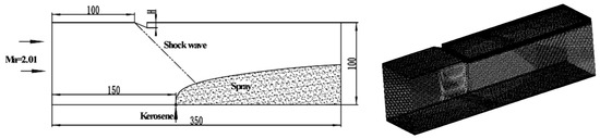
Figure 1.
Physical model and grid (unit/mm).

Table 1.
Values of H in different cases.
Kerosene was mixed with the mainstream in crossflow. The nozzle diameter (D) was 1 mm. The inlet Mach number was 2.01; the total temperature was 300 K, and the fuel–air momentum ratio was 12. This is a typical working condition of the combustor and can ensure that the jet has a certain penetration depth. A structured grid was used. The height of the first layer was 0.05 mm, and Y+ was less than 3. The total number of grids was 3.8 million.
2.3. Numerical Method Verification
To verify the accuracy of the numerical method, the operating condition without an incident shock wave (CASE0) was simulated. The droplet distribution is shown in Figure 2, where the diameter and color of the circle represent the droplet size. The following conclusions can be made: (1) After the large-size droplet is ejected from the nozzle, due to the K-H unstable wave, the small-diameter droplet is gradually peeled off from the surface of the large-size droplet. These small droplets travel downstream with the airflow, forming a spray. In the process of moving, the diameter of the large droplet gradually decreases as the small droplet is gradually peeled off. When the movement time of large droplets is longer than the breaking characteristic time, the Rayleigh–Taylor (R-T) instability comes into play. The large droplet is further broken into smaller droplets, and the diameter of the droplet on the outer edge of the jet is larger than that of the droplet near the wall. (2) The simulation results of CASE0 were compared with the fitting relations of penetration depth obtained from tests conducted by Gopala [21] and Li [22], and the comparison results are shown in Figure 2. It can be seen that the numerical method adopted in this paper is in good agreement with the experimental results, and this method can be used to study the effect of shock waves on the atomization characteristics of kerosene in crossflow.
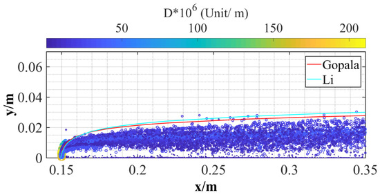
Figure 2.
Comparison results between the numerical simulation and the test.
3. Results and Analysis
3.1. Influence of Shock Waves on Jet Characteristics in the Central Section
The penetration depth is a very important parameter in the study of the atomization characteristics of kerosene in crossflow. The penetration depth is the depth of the liquid jet through the main flow, which determines the atomization and mixing degree of the jet. The particle size distribution in the central section can characterize the penetration characteristics of the jet. Figure 3 shows the particle size distribution of the droplet in the central section of the jet in different cases, where the diameter and color of the circle represent the size of the droplet. The following can be seen from the results: (1) When there is no incident shock, there is a certain distance between the inner edge of the jet and the lower wall surface, and there is a long pure gas zone between the jet and the combustor wall. The species in this zone are almost all gaseous, with only a few liquid drops. The particle size upstream of the jet is larger than the size downstream, and the particle size of the inner edge of the jet is smaller than that of the outer edge. (2) When there is a shock wave, the outer-edge trajectory of the jet does not change much, but the inner-edge trajectory is close to the combustion chamber wall. Moreover, the length of the pure gas zone gets shorter. (3) With the shock wave moving upstream, the pure gas region is pushed farther towards the jet root (the outlet of the orifice) and is divided into two parts.
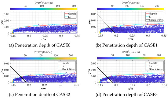
Figure 3.
Influence of different incident positions on penetration depth (z = 0 m).
Figure 4 shows the influence of different incident positions on the concentration distribution of kerosene in the jet center section. Due to the K-H instability, obvious surface waves appear on the upper surface of the jet, and Lmax is the farthest distance affected by the surface wave. When X is greater than Lmax, the outer edge of the spray is relatively smooth. The following can be seen from the results: As the incident point moves upstream, (1) the surface wave moves upstream; the wavelength becomes shorter, and Lmax gradually decreases. This indicates that, due to the effect of shock waves, the unsteadiness of the jet root is strengthened, while the unsteadiness downstream of the jet is weakened. In other words, the jet accelerates atomization and achieves stability more quickly. (2) The high-concentration core area becomes shorter, and the penetration depth of the jet in front of the shock wave increases. The height of the central trajectory increases. Case0 is L, and Case1 is L + 0.5 D. Due to the small movement of the incident position of the shock wave, the heights of the central trajectory of CASE2 and Case3 are not much different, both of which are L + 1.25 D.
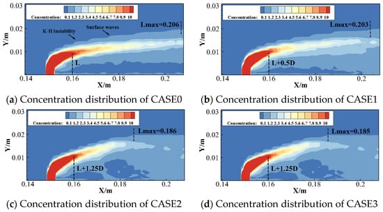
Figure 4.
Concentration distribution of liquid kerosene at different incident locations (z = 0 m).
In order to analyze the causes of the above changes, the influence of the shock wave incident position on the flow-field characteristics of the jet center section were obtained, as shown in Figure 5. When the shock wave interacts with the jet, a reflux region is formed in the shock front. When the incident point of the shock wave moves upstream, the reflux region will move upstream. Due to the influence of the jet root, a new reverse reflux region will be formed, and the area of the reflux region will increase. The change in the characteristics of the reflux region leads to the change in the characteristics of the jet.
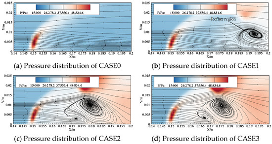
Figure 5.
Influence of different incident locations on flow-field characteristics (z = 0 m).
3.2. Influence of Shock Waves on Jet Characteristics in the Transverse Section
The SMD of different sections was counted along the flow direction, and the results are shown in Figure 6. It can be seen that when there is no incident shock, the SMD does not change much after the X = 20 D section, and when there is an incident shock, the SMD does not change much after the X = 60 D section. After the incident shock wave, the SMD of the cross section becomes significantly smaller and further decreases as the shock wave moves upstream of the jet.
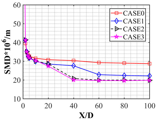
Figure 6.
SMD of different sections along the flow direction.
The histograms of the particle size distribution in different sections of CASE0 and CASE4 were obtained, as shown in Figure 7. The distribution of the droplet diameter generally increases first and then decreases, and the particle size distribution is approximately Gaussian, which is similar to the results obtained by Inamura [23] and Wu [24]. Compared with the condition without an incident shock wave, when there is an incident shock wave, the bandwidth of the particle size distribution before X = 10 D is not affected, but the bandwidth of the particle size distribution downstream of the jet decreases gradually and concentrates in the area of small particle size. After X = 40 D, the particle size bandwidth is essentially unchanged.
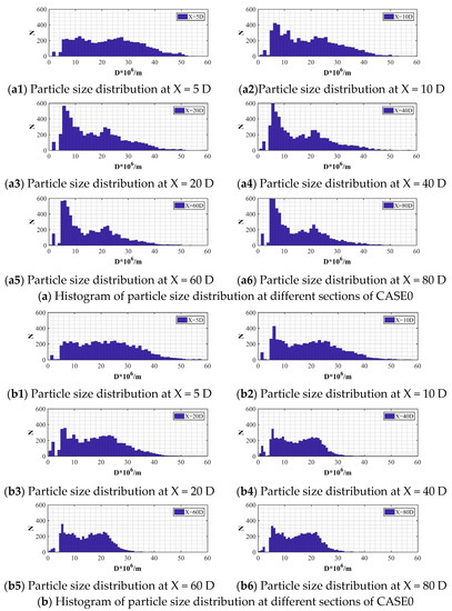
Figure 7.
Histogram of the particle size distribution in different sections.
Figure 8 shows the spatial distribution of droplets spanwise at different incident positions at X = 80 D. It can be seen that large droplets are not only distributed in the periphery of the spray, but also in the middle of the spray. When a shock wave is incident, the spatial distribution of the droplet is more uniform. The droplet distribution area moves to the lower wall of the combustion chamber; as the incident point of the shock wave moves upstream of the jet, the spatial distribution of the droplets becomes more uniform.
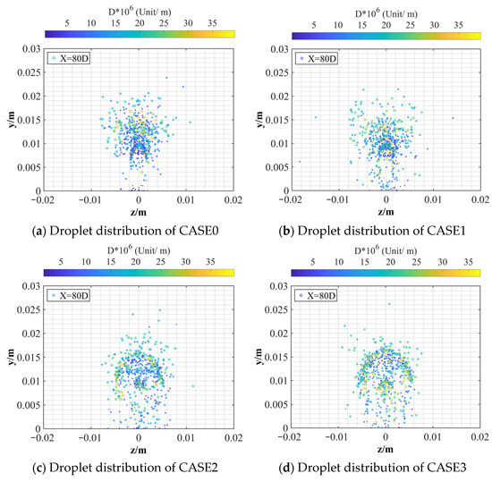
Figure 8.
Influence of different incident positions on spanwise distribution of droplet (X = 80 D).
Figure 9 shows the Mach number distribution characteristics at different incident locations. When there is no incident shock wave, the flow field has an obvious subsonic region due to the momentum exchange between the droplet and the mainstream. As the shock wave moves upstream, the subsonic region moves towards the lower wall of the combustor, and the subsonic region gradually becomes smaller. This shows that the shock wave accelerates the momentum exchange between the droplet and the mainstream, making the distribution of the droplets more uniform.
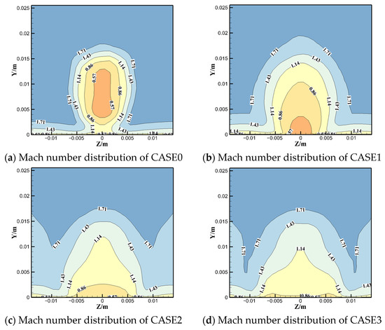
Figure 9.
Influence of different incident locations on the Mach number distribution (X = 80 D).
3.3. Influence of Shock Waves on Jet Characteristics in the Spanwise Section
The particle size distribution of the y = 0.01 m section was selected to analyze the effect of shock waves on the atomization angle, and the results are shown in Figure 10. When there is no incident shock, the width of the jet increases gradually. When a shock wave is incident, the width of the jet increases first and then decreases. This change becomes more obvious as the shock wave moves upstream of the jet. In the initial stage, large droplets are mainly distributed in the middle of the jet, while small droplets are distributed at both the edge and the middle of the jet. When a shock wave is incident, large droplets will disappear more quickly, and the particle size of the jet tends to become uniform more quickly.
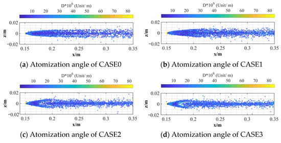
Figure 10.
Influence of different incident positions on the atomization angle (y = 0.01 m).
Figure 11 shows the influence of different incident locations on the pressure distribution in the y = 0.01 m section. The following can be seen: (1) When there is no incident shock wave, due to the obstruction of the jet, a shock wave appears at the jet root and a high-pressure region is formed. As the incident shock wave moves upstream, the high-pressure region at the root of CASE1 and CASE2 is essentially unchanged, but the high-pressure region at the root of CASE3 changes. (2) When there is no incident shock wave, there is no adverse pressure gradient downstream of the jet root. When there is an incident shock wave, the adverse pressure gradient will be formed downstream of the jet root, and with the shock wave moving upstream, this leads to the change in the atomization angle.
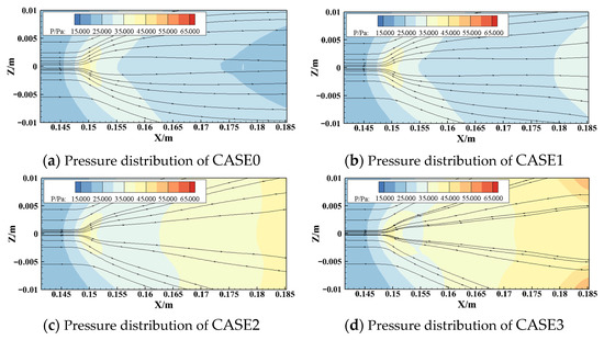
Figure 11.
Influence of different incident locations on the pressure distribution (y = 0.01 m).
4. Conclusions
The effect of different incident positions of a shock wave on the atomization characteristics in crossflow was studied by a precise unsteady simulation method. It focused on the changes of atomization characteristics in the center, transverse, and spanwise sections at different incident positions. The following conclusions were obtained:
- When there is a shock wave, the outer-edge trajectory of the jet does not change much, but the inner-edge trajectory is close to the combustion chamber wall. Additionally, the length of the pure gas zone gets shorter. With the shock wave moving upstream, the pure gas region is pushed further towards the jet root and is divided into two parts. Meanwhile, the incident shock wave changes the K-H instability of the jet. The unsteadiness of the jet root is strengthened, while the unsteadiness downstream of the jet is weakened. The main reason for the characteristic change is the change in the reflux region caused by the incident shock wave.
- Because the incident shock wave changes the momentum exchange characteristics between the mainstream and the jet, the SMD of the transverse section of the jet decreases, and the droplet distribution becomes more uniform.
- Due to the adverse pressure gradient caused by the incident shock wave, the width of the jet increases first and then decreases, and this change becomes more obvious as the shock wave moves upstream of the jet.
In this study, the temperature of kerosene and inflow was 300 K, and the influence of different temperatures was not considered, which weakens the influence of evaporation. This will be studied in the future.
Author Contributions
Conceptualization, Y.Z. and J.W.; methodology, Y.Z.; software, Y.Z.; validation, Y.Z., J.W. and X.M.; formal analysis, Y.Z.; investigation, Y.Z. and X.M.; resources, Y.Z.; data curation, Y.Z. and X.M.; writing—original draft preparation, Y.Z.; writing—review and editing, Y.Z.; visualization, J.W.; supervision, J.W.; project administration, J.W.; funding acquisition, Y.Z. All authors have read and agreed to the published version of the manuscript.
Funding
This research received no external funding.
Data Availability Statement
Data is available through corresponding author.
Conflicts of Interest
The authors declare no conflict of interest.
References
- Charles, R. McClinton. X-43-scramjet power breaks the hypersonic barrier Dryden lectureship in research for 2006. In Proceedings of the 44th AIAA Aerospace Sciences Meeting, Reno, NV, USA, 9–12 January 2006. [Google Scholar]
- Ronald, S. A Century of Ramjet Propulsion Technology Evolution. J. Propuls. Power 2004, 20, 27–58. [Google Scholar]
- Seiner, J.; Dash, S.; Kenzakowshi, D. Historical Survey on Enhanced Mixing in Scramjet Engines. J. Propuls. Power 2001, 17, 1273–1286. [Google Scholar] [CrossRef]
- Takahashi, H.; Masuya, G.; Hirota, M. Effects of Injection and Main Flow Conditions on Supersonic Turbulent Mixing Structure. AIAA J. 2010, 48, 1748–1756. [Google Scholar] [CrossRef]
- Rana, Z.A.; Thornber, B.; Drikakis, D. Transverse jet injection into a supersonic turbulent cross-flow. Phys. Fluids 2011, 23, 585. [Google Scholar] [CrossRef]
- Rana, Z.A.; Thornber, B.; Drikakis, D. On the importance of generating accurate turbulent boundary condition for unsteady simulations. J. Turbul. 2011, 12, N35. [Google Scholar] [CrossRef]
- Génin, F.; Menon, S. Dynamics of sonic jet injection into supersonic crossflow. J. Turbul. 2010, 11, 1–30. [Google Scholar] [CrossRef]
- Nakamura, H.; Sato, N.; Kobayashi, H.; Niioka, T.; Masuya, G. Combustion of transverse hydrogen injection with shock wave in a supersonic airstream. In Proceedings of the 5th Asia-Pacific Conference on Combustion, Adelaide, SA, Australia, 17–20 July 2005. [Google Scholar]
- Tahsini, A.M.; Mousavi, S.T. Investigating the supersonic combustion efficiency for the jet-in-cross-flow. Int. J. Hydrogen Energy 2015, 40, 3091–3097. [Google Scholar] [CrossRef]
- Shekarian, A.A.; Tabejamaat, S.; Shoraka, Y. Effects of incident shock wave on mixing and flame holding of hydrogen in supersonic air flow. Int. J. Hydrogen Energy 2014, 39, 10284–10292. [Google Scholar] [CrossRef]
- Mai, T.; Sakimitsu, Y.; Nakamura, H.; Ogami, Y.; Kudo, T.; Kobayashi, H. Effect of theincident shock wave interacting with transversal jet flow on the mixing and combustion. Proc. Combust. Inst. 2011, 33, 2335–2342. [Google Scholar] [CrossRef]
- Schetz, J.A.; Maddalena, L.; Burger, S.K. Molecular weight and shock-wave effects on transverse injection in supersonic flow. J. Propuls. Power 2010, 26, 1102–1113. [Google Scholar] [CrossRef]
- Erdem, E.; Saravanan, S.; Lin, J.; Kontis, K. Experimental investigation of transverse injection flowfield at Mach 5 and the influence of impinging shock wave. In Proceedings of the 18th AIAA/3AF International Space Planes and Hypersonic Systems and Technologies Conference, Tours, France, 24–28 September 2012. [Google Scholar]
- Huang, W.; Tan, J.G.; Liu, J.; Yan, L. Mixing augmentation induced by the interaction between the oblique shock wave and a sonic hydrogen jet in supersonic flows. Acta Astronaut. 2015, 117, 142–152. [Google Scholar] [CrossRef]
- Huang, W.; Wang, Z.G.; Wu, J.P.; Li, S.B. Numerical prediction on the interaction between the incident shock wave and the transverse slot injection in supersonic flows. Aerosp. Sci. Technol. 2013, 28, 91–99. [Google Scholar] [CrossRef]
- Gerdroodbary, M.B.; Ganji, D.D.; Amini, Y. Numerical study of shock wave interaction on transverse jets through multiport injector arrays in supersonic crossflow. Acta Astronaut. 2015, 115, 422–433. [Google Scholar] [CrossRef]
- Menter, F.R. Two-Equation Eddy-Viscosity Turbulence Models for Engineering Applications. AIAA J. 1994, 32, 1598–1605. [Google Scholar] [CrossRef]
- Xing, J.-W.; Yang, Y. Three-dimensional simulation of H2O vitiation effects on combustor performance for scramjet. J. Propuls. Technol. 2011, 32, 5–10. [Google Scholar]
- Thomas, R.A.; Bussing Murmant, E.M. Finite-Volume Method for the Calculation of Compressible Chemically Reacting Flows. AIAA J. 1988, 26, 1070–1078. [Google Scholar]
- Zhai, X.F.; Bai, H.C.; Li, C. Numerical simulation of atomization of liquid jet in supersonic flow. Phys. Gases 2021, 6, 23–29. [Google Scholar]
- Gopala, Y.; Zhang, P.; Bibik, O.; Lubarsky, E.; Zinn, B. Liquid fuel jet in crossflow-trajectory correlations based on the column breakup point. In Proceedings of the 48th AIAA Aerospace Sciences Meeting Including the New Horizons Forum and Aerospace Exposition, Orlando, FL, USA, 4–7 January 2010. [Google Scholar]
- Li, L.; Lin, Y.; Xue, X.; Gao, W.; Sung, C.J. Injection of liquid kerosene into a high-pressure subsonic air crossflow from normal temperature. In Proceedings of the ASME Turbo Expo 2012: Turbine Technical Conference and Exposition, Copenhagen, Denmark, 11–15 June 2012. [Google Scholar] [CrossRef]
- Inamura, T.; Nagai, N. Spray Characteristics of Liquid Jet Traversing Subsonic Airstreams. J. Propuls. Power 1997, 13, 250–256. [Google Scholar] [CrossRef]
- Wu, P.K.; Kirkendall, K.A.; Fuller, R.P.; Nejad, A.S. Spray Structures of Liquid Jets Atomized in Subsonic Crossflows. J. Propuls. Power 1998, 14, 173–182. [Google Scholar] [CrossRef]


Disclaimer/Publisher’s Note: The statements, opinions and data contained in all publications are solely those of the individual author(s) and contributor(s) and not of MDPI and/or the editor(s). MDPI and/or the editor(s) disclaim responsibility for any injury to people or property resulting from any ideas, methods, instructions or products referred to in the content. |
© 2022 by the authors. Licensee MDPI, Basel, Switzerland. This article is an open access article distributed under the terms and conditions of the Creative Commons Attribution (CC BY) license (https://creativecommons.org/licenses/by/4.0/).