Abstract
This paper presents the development, analysis, and performance evaluation of a novel transversal-feed Electron Cyclotron Resonance Plasma Thruster (ECRPT). The ECRPT operates based on the transversal-feed principle and incorporates optimized structural design. Through extensive simulation of the S-parameters of the antenna, optimal antenna sizes are determined for both coaxial and transversal-feed configurations. Additionally, the electric field intensity of the antenna is simulated for both feed structures, revealing higher electric field intensity in the transversal structure, thereby promoting discharge. We employ the drift-diffusion model to calculate the number density of electrons in the discharge chamber and ascertain that the number density can reach an order of magnitude of 1018 m−3. Experimental discharge tests are conducted under various microwave power conditions, demonstrating that the thruster can initiate and cease operation with an incident power as low as 5 W, significantly lower than that of traditional coaxial feed structures. At a power level of 20 W, the ion current density can attain 3 A/m2. Moreover, the transversal-feed thruster exhibits exceptional performance when the power exceeds 10 W, and the propellant flow rate ranges from 0.5 SCCM to 5 SCCM. The superior performance characteristics of the proposed thruster configuration make it a promising candidate for applications demanding efficient and low-power plasma propulsion systems.
1. Introduction
An electron cyclotron resonance plasma thruster (ECRPT) is a kind of quasi-neutral electric propulsion device. It has the characteristics of high ionization performance of an ECR source and does not need a neutralizer. The electrons and ions are ejected simultaneously in the magnetic nozzle [1,2,3]. Its long life, moderate specific impulse, simple structure, and high reliability are suitable for long-term space flight missions such as deep space exploration [3,4,5,6].
The United States, France, and Japan have performed many studies on ECRPTs. NASA Marshall Space Flight Center (MSFC) conducted experimental research. The results show that the propellant absorbs microwave energy by means of electron cyclotron resonance to generate a high-density plasma. The plasma density in the plume reaches the order of 1013–1016 m3, and the ion velocity reaches 20–30 km/s [7]. The French Aerospace Lab (ONERA) used Xenon as the propulsion gas and studied the effects of mass flow and microwave power on the ion current and ion energy distribution. When the microwave power was 50 W, the mass utilization efficiency reached 45%, and the ion energy reached 350 eV [1]. Kyoto University used a two-dimensional axisymmetric particle model of the Monte Carlo collision algorithm to perform a numerical simulation of ECRPT. The numerical calculation was performed at a microwave frequency of 4 GHz and a magnetic induction intensity of 1430 Gauss. The results show that the magnetic field can effectively confine the electrons, and the ions are expelled using the electrostatic field in space. This also verifies the electron cyclotron resonance effect in the discharge chamber region. Finally, the electron number density can reach the order of 1016 m−3 [8]. Inchingolo [9] developed HYPHEN, a 2D model simulating the circular waveguide ECRT concept, and used it to study the EP2 ECRT prototype. This simulation model can be used to evaluate the extent to which the power deposition profile, the ECR region position, and the operating point affect the thrust and plasma transport variables in the magnetic nozzle. Furthermore, Magarotto [10] presents a numerical suite of cathodeless plasma thrusters and discusses their utilization at low power (50 W range). This numerical suite is well suited as a simulation tool for electrodeless ECRPT to study plasma properties and optimize thruster performance.
However, most of the above traditional ECRPTs transfer energy via coaxial waveguides, i.e., the coaxial ECRPT. The coaxial ECRPT has low energy transfer efficiency, and the power required for generating plasma is at least 20 W [1], which can hardly meet the requirements of new low-power space tasks, such as the demand for low-power electric propulsion of micro-nano satellites [11,12,13]. Therefore, in this paper, a novel ECRPT is proposed, in which the energy-feeding structure is changed into the transversal feed to greatly reduce the starting power of the thruster by enhancing the local electric field. Additionally, the simulation and experimental research on the transversal-feed ECRPT are carried out to verify the feasibility of the transversal-feed structure.
2. ECRPT with Transversal-Feed Structure
2.1. Thruster System Structure
The structure of the transversal-feed ECRPT is shown in Figure 1, which is mainly composed of a magnetic circuit system, a microwave energy transmission system, a propellant supply system, a discharge chamber, an RF antenna, and a microwave incident chamber. The microwave transmission mode is TEM mode. In the chamber of the thruster, a magnetic mirror phenomenon occurs due to the role of the ring magnet, thereby forming a magnetic nozzle effect. The coupling antenna is connected to a microwave source via a coaxial wire and uses 2.45 GHz microwave energy to ionize the propellant. The microwave incident chamber is an important component of the transversal-feed ECRPT that is different from the traditional coaxial ECRPT. The microwave energy is transmitted to the coupling antenna via the coaxial antenna, which is transversal to the incidence chamber, and the microwave energy is transmitted to both ends of the antenna. The energy transmitted to the left end will be reflected using the metal barrier, and the reflected microwave will be transmitted to the right end. In the transmission process, two microwaves with the same frequency and the same phase will generate a microwave resonance phenomenon so that the energy transmitted to the discharge end of the antenna reaches the maximum value, thereby improving the efficiency of the microwave transmission system. The thruster structure mainly has two advantages: first, unlike the traditional electron cyclotron resonance ion thruster (ECRIT) [14], the grid structure is eliminated at the end of the thruster, and the plasma is accelerated via the magnetic field at the end of the permanent magnet, so that the electrons and ions are ejected at the same time, achieving the effect of self-neutralization. Secondly, it breaks through the traditional coaxial energy feeding method [15] and uses a structure that feeds microwave energy transversally to improve the energy transmission efficiency.
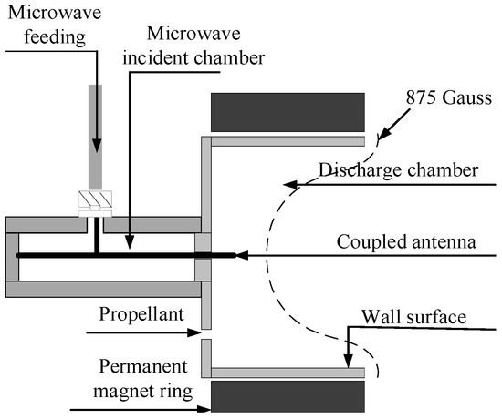
Figure 1.
Thruster structure.
2.2. Microwave Antenna Simulation
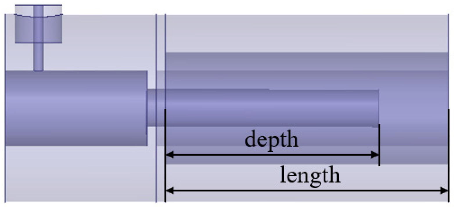
There are two goals to be achieved in antenna simulation: (1) Determining the structure of the antenna by comparing and analyzing the antenna performance through simulation calculation; (2) Determining the depth and length of the antenna by comparing and analyzing the S-parameters and electric field distribution of the antenna via simulation calculation.
In the antenna simulation, the most important thing is to study the S-parameters. S12 is the isolation, also known as the reverse transmission coefficient; S21 is the gain, which is the forward transmission coefficient; input return loss is also called input reflection coefficient, which is represented by S11; output return loss is also called output reflection coefficient, which is represented by S22. Define the ratio of incident power to reflected power as return loss (RL), expressed in dB; the ratio of reflected voltage to incident voltage is the reflection coefficient (Г), which is a scalar; voltage standing wave ratio (VSWR) represents the ratio of antinode voltage to node voltage. The relationship between the four is as follows:
2.2.1. Transversal-Feed Structure
The transversal-feed simulation model is shown in Figure 2. We use wave port excitation mode and radiation boundary condition. The microwave input port material is copper, and the coaxial line is Teflon vinyl resin. Both the discharge chamber and the microwave incident chamber are set as a quartz tube. After the component materials are set, the size of each component of the thruster is optimized. During the optimization process, the antenna length of the thruster and the depth of the antenna feeding into the microwave port are considered. We will analyze the results and determine the optimal parameters.
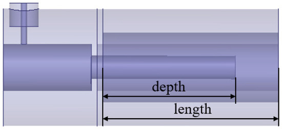
Figure 2.
Transversal-feed simulation model.
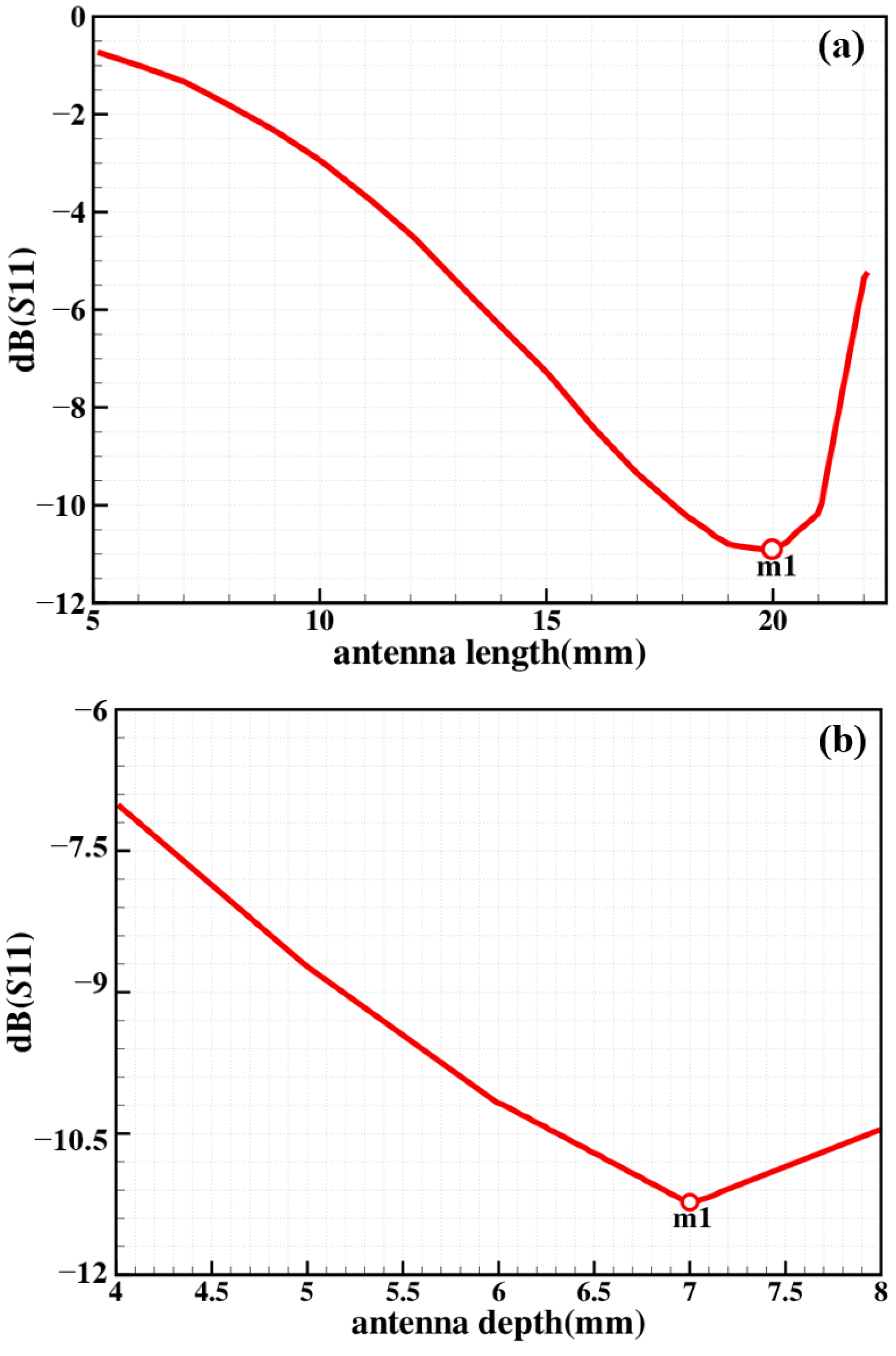
Figure 3 shows the relationship of transversal-feed structure between the S-parameters(S11) and antenna parameters. From Figure 3a, it can be seen that the S-parameters first decrease and then increase with the increase in the antenna length. The inflection point is near m1(20, −10.9247). According to the S-parameter characteristics, 20 mm is selected as the optimal parameter of the antenna length. It can be seen from Figure 3b that m1 is the inflection point of the relationship between the antenna depth and the S-parameter, and the optimal depth of the antenna is 7 mm.
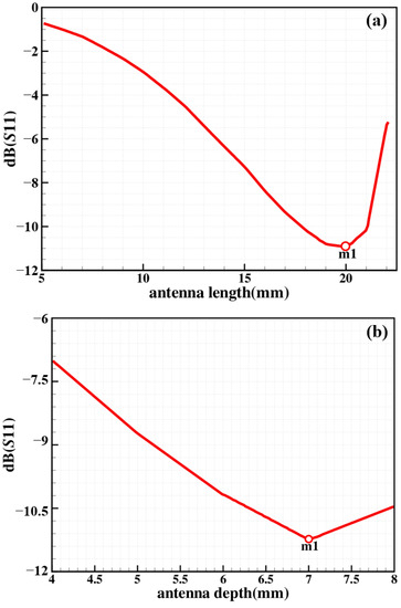
Figure 3.
Relationship between S-parameters and antenna parameters of transversal-feed structure.
2.2.2. Coaxial-Feed Structure
The same method was used to simulate the coaxial-feed structure, and the influence of the two feeding structures on the electric field intensity distribution of the thruster was compared and analyzed. The simulation model is shown in Figure 4. The material settings are the same as the transversal-feed structure. The excitation source also uses wave port excitation. The relationship between the S-parameter and antenna length and the relationship between the S-parameter and antenna position were simulated, respectively.
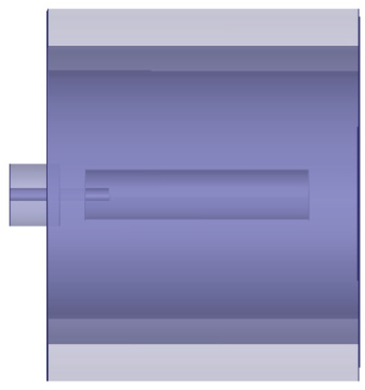
Figure 4.
Coaxial-feed simulation model.
Figure 5 shows the relationship of coaxial structure between S-parameters and antenna parameters. It can be seen from Figure 5a that there is an inflection point at m1, but the minimum S11 parameter is not lower than −2.25 dB. It can be considered that different antenna lengths have little effect on energy transmission, and in order to compare with the transversal-feed structure, 20 mm is selected as the antenna length value, which is selected in the transversal-feed structure. From Figure 5b, it can be seen that the antenna depth can be selected after m2(9, −27.7843), and 10 mm is selected as the optimal depth during simulation.

Figure 5.
Relationship between S-parameters and antenna parameters of coaxial-feed structure.
2.2.3. Electric Field Intensity Distribution
Assuming that the velocity component of the electron parallel to the magnetic field remains unchanged, the average energy obtained by the electron via an ECR resonance region can be calculated by the following formula [16]:
where is the gradient of the magnetic induction intensity along the magnetic field line, and is the microwave electric field intensity perpendicular to the direction of the magnetic field line. Therefore, in order to obtain higher energy electrons, needs to be as large as possible.
The antenna electric field intensity of coaxial-feed and transversal-feed structures are simulated, as shown in Figure 6. The microwave incident power is 10 W. Figure 6a is a coaxial-feed structure, and Figure 6b is a transversal-feed structure. It can be seen from the simulation results that the electric field intensity of the two feed structures can reach the order of 103–104 V/m in the discharge chamber region, which meets the energy requirements of the antenna for exciting the propellant. At the same time, the transversal-feed structure has a higher electric field intensity in the discharge region than the coaxial-feed structure, which indicates that the transversal-feed structure makes it easier to ionize the propellant according to Equation (4). This is due to the microwave resonance phenomenon in the transversal structure.
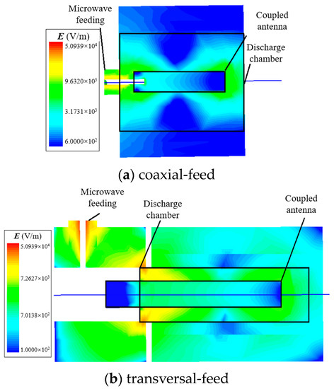
Figure 6.
Antenna electric field intensity (V/m).
2.3. Design of Discharge Chamber
The discharge chamber is the key structure of the thruster. Ionization of the propellant and acceleration of the plasma occur in the discharge chamber. The propellant flowing into the discharge chamber is ionized using the coupled antenna to form plasma, and the electrons make a cyclotron motion under the magnetic field. At this time, the effect of the microwave electric field on the electrons in the cyclotron motion can be equivalent to the effect of a constant electric field on the electrons in the linear motion. Therefore, the electrons are continuously accelerated under the combined action of the magnetic field and the microwave electric field, and the energy is continuously obtained from the microwave field. They eventually became high-energy electrons [14].
In the simulation, the characteristics of the plasma were simulated using finite element simulation software (COMSOL). The dynamics were modeled using electrostatic theory and plasma transport theory, which were used to calculate plasma parameters [17]. The electric field equation affecting the dynamics of electrons and ions in plasma can be expressed as:
where E is an electric field, ρq is free charge density, ε is permittivity in medium, V is potential. The potential distribution can be obtained by solving (5) through the free charge density source term and boundary conditions, and then the electric field distribution can be obtained from (6). The transport theory was used to estimate the characteristics of the plasma, such as the electron temperature, number density of ions, and electrons.
where ne is the electron number density, Re is the electron creation rate, u is the ion velocity, Γe is the electron flux vector, nε is the electron energy density, Γε is the electron energy flux vector, De is the electron diffusivity, Dε is the electron energy diffusivity, Sen is the energy loss or gain due to inelastic collisions, Q is the external heat source, and Qgen is the generated heat source.
The transport of neutral and ion gas in the plasma was determined using the continuity equation presented as follows [17]:
where subscript k represents the kth species, wk is the mass faction, u is the mass averaged fluid velocity, jk is the diffusive flux vector, Rk is the creation rate expression, Vk is the diffusion velocity, Dk is the diffusion coefficient, Mn is the mean molar mass of the mixture, DkT is the thermal diffusion coefficient, T is the gas temperature zk is the charge number, μk is the mixture averaged mobility.
We consider Argon plasma chemistry with a set of collisions described in Ref. [18], as shown in Table 1. Because of the low power of the microwave, we do not consider multiply charged Argon ions.

Table 1.
Collisions and reactions modeled.
The thruster model is determined via the optimized design. The magnetic circuit system uses a samarium cobalt permanent magnet ring with an inner diameter of 3 cm, an outer diameter of 5 cm, and a height of 2.5 cm. The thruster discharge chamber has an inner diameter of 2.8 cm, an outer diameter of 3 cm, and a height of 2.5 cm. The operating conditions for this simulation are that incident power is 10 W, background pressure is 1 Pa, and propellant is argon. Figure 7 shows the distribution of electron number density in the designed transversal-feed discharge chamber, and the 875 Gauss magnetic induction contour is marked with a green line. Based on the principle of electron cyclotron resonance, under the microwave frequency of 2.45 GHz, the electrons will make a cyclotron motion around the 875 Gauss contour line, thereby greatly increasing the collision frequency with neutral gas and forming high-density plasma. It can be seen from the Figure 7 that the electron number density of the discharge chamber can reach the order of 1018 m−3. The higher ion number density benefits from the dual excitation effect of microwave resonance and electron cyclotron resonance achieved in the transversal feed.
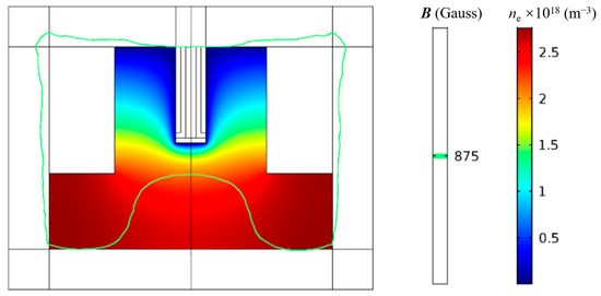
Figure 7.
Distribution of electron number density in the discharge chamber.
3. Experimental Verification
3.1. Experimental Scheme
The thruster system was placed in a vacuum chamber for experiments. The diameter of the vacuum chamber is 1m, and the length is 1.5 m. During the experiment, the vacuum degree of the vacuum chamber is 10−1~10−2 Pa. The vacuum obtaining system consists of 18 L/s RVD-18 rotary vane vacuum pump and 150 L/s ZJP-150 roots vacuum pump.
The microwave source provides the energy required by the coupled antenna to excite the ionized propellant gas. The magnitude of the microwave power affects the ionization effect of the propellant. We use a 2.45 GHz solid-state microwave power source to power the thruster and change the operating conditions by controlling the output power. Keep the thruster working for about 1 min before the experiment starts so that the thruster is in a thermal equilibrium state. Argon was used as the propellant. The ion current density in the plume region was measured using the Faraday probe [19] in the thruster plume region. The probe shell and collector are biased at −30 V, which will collect ions and reject electrons.
The retractable movable bracket was used to fix the Faraday probe, and the thruster is fixed on the non-magnetic stainless steel bracket. The height of the probe can be adjusted up and down according to the position of the plume region of the thruster, as shown in Figure 8. The voltage on the sampling resistor was measured using a RIGOL four-channel digital oscilloscope to calculate the ion current in the plume region.
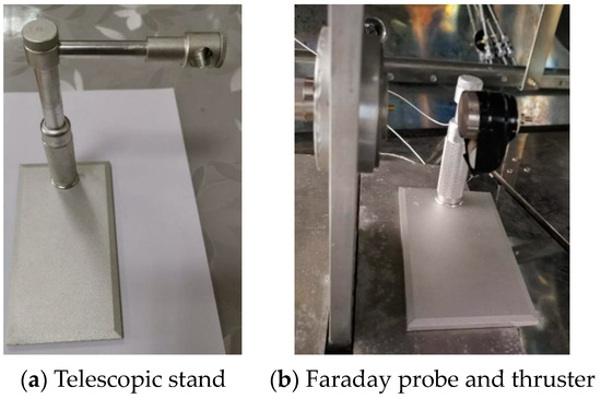
Figure 8.
Plume diagnostic devices.
3.2. Measurement of Ion Current Density under Different Microwave Power Conditions
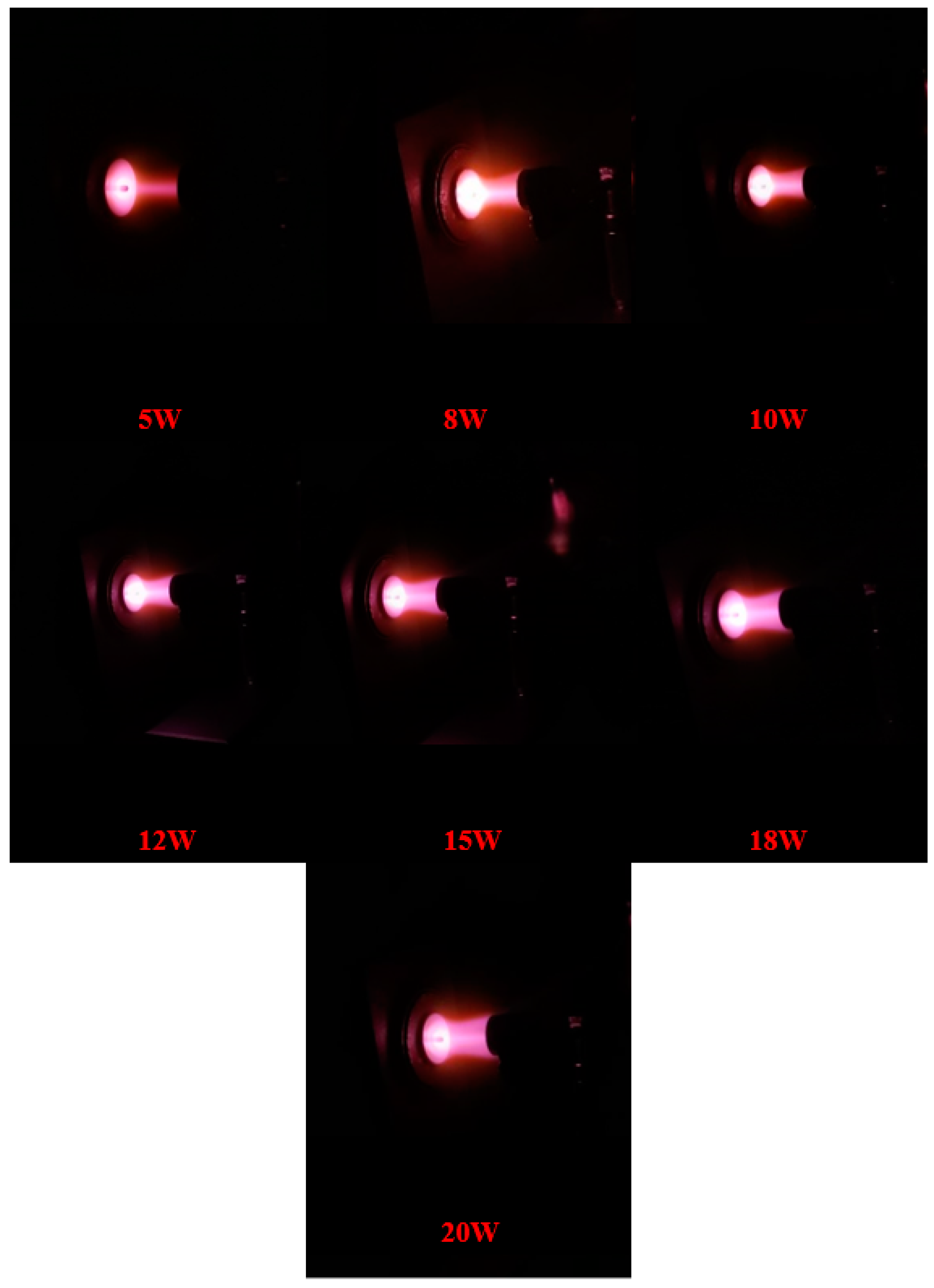
In this section, experimental studies of different microwave powers were carried out under the conditions of a pressure of 10−2 Pa and a mass flow rate of 0.5 SCCM. The ion current densities of the thruster plume region under microwave power conditions of 5 W, 8 W, 10 W, 12 W, 15 W, 18 W, and 20 W were analyzed and compared. Figure 9 shows the thruster discharge under different power conditions.
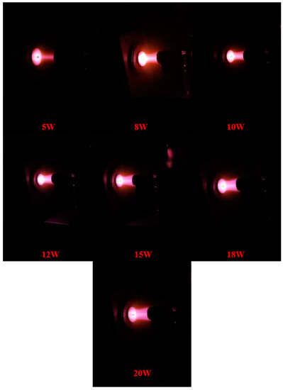
Figure 9.
Thruster discharge under different power conditions.
It can be seen from the Figure 9 that with the continuous increase in power, the discharge effect of the thruster plume becomes more and more obvious, and the width and brightness of the plume region increase with the increase in power. We can start and stop the thruster under the condition that the incident power is 5 W and the discharge can be maintained at 3 W by observation. Compared with other studies [1], we have significantly reduced the start-stop power and working power of the thruster. In order to study the trend of the thruster plume region with power, the ion current in the plume region was measured using a Faraday probe in the experiment, and the ion current density was calculated. During the experiment, the sampling resistance was 10 kΩ, the gas flow was 0.5 SCCM, the cross-sectional area of the probe collector was 4.155 cm2, and the voltage at different powers was measured with an oscilloscope. Table 2 shows the ion current and ion current density in the plume region at different powers.
Table 2.
Ion current and ion current density in plume region at different powers.
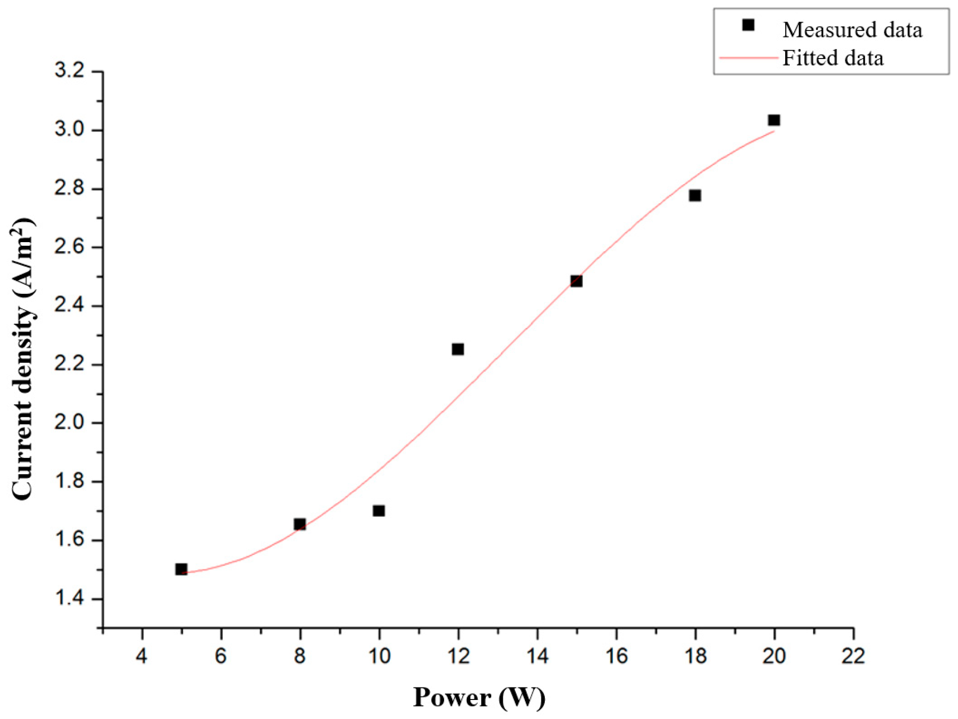
It can be seen from the collected data that the ion current in the plume region gradually increases with the increase in power. At a power of 20 W, the ion current density can reach 3 A/m2. In order to observe the changing trend of ion current in the plume region, a fitting curve of ion current density with power was fitted, as shown in Figure 10. It can be intuitively seen from the Figure that in the case of more than 10 W, the ion current density is higher, and the propellant is more fully ionized.
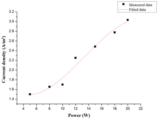
Figure 10.
Fitting curve of ion current density with power.
3.3. Measurement of Ion Current Density under Different Mass Flow Conditions
Since the excitation and ionization of the propellant are related to conditions such as pressure and microwave power, the thrust does not increase linearly with the increase in the propellant flow. Therefore, exploring the relationship between the propellant mass flow rate and the ion current density in the plume area is very important to improve the thrust efficiency. In this section, the experimental research is carried out under the conditions of 10−2 Pa, argon gas, and 20 W microwave power. The ion current density of the thruster plume area under different propellant mass flow conditions is analyzed and compared.
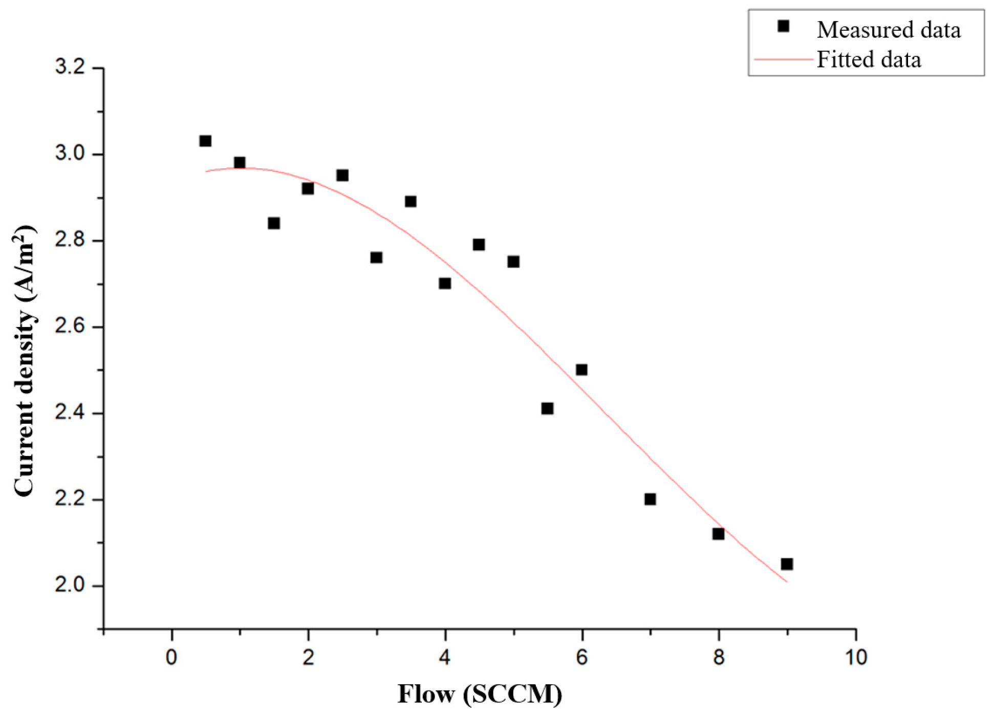
In order to explore how the working medium gas affects the discharge effect of the thruster, this paper has measured the ion current density of the plume area under different propellant gas flow rates from 0.5 SCCM to 9.0 SCCM using a Faraday probe. The fitting curve of ion current density with propellant gas flow is shown in Figure 11.
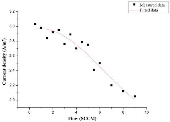
Figure 11.
Fit curve of ion current density with propellant gas flow.
It can be drawn from the table that the ion current density varies between 2.05 and 3.03 A/m2, and the ion current density continuously decreases with the increase in the propellant flow. When the gas flow rate increases, it causes an increase in the number of collisions between the electrons and the gas atoms. As a result, the energy transferred from the electrons to the gas particles increases, causing an increase in the gas temperature by lowering the electron temperature. The lower electron temperature reduces the electron velocity, which results in a lower collected current density.
In addition, it can be seen from the line graph that when the working fluid gas flow rate is greater than 5 SCCM, the ion current density in the plume area decreases significantly. According to the experimental data, the size of the thruster is more suitable for a flow rate of less than 5 SCCM.
4. Conclusions
In this paper, a novel transversal-feed ECRPT is presented. The electromagnetic fields of different types of excitation antennas are simulated first. The optimization design of the antenna structure is mainly to improve the utilization efficiency of microwave power and reduce the discharge power. Considering the microwave resonance and ECR effect, a microwave incident chamber is added to the head of the thruster discharge chamber to form the microwave resonance. The simulation results show that under the optimal antenna structure, the transversal-feed method can obtain a higher electromagnetic field and make the electron energy higher. The static magnetic field model was used to simulate the magnetic circuit system, and the distribution characteristics of the magnetic field and the ECR surface of the discharge chamber were obtained. Through continuous simulation, the structural size parameters of the discharge chamber were finally obtained.
The experimental prototype of the ECRPT principle was investigated. The experimental research was carried out with argon. The ion current and ion current density in the plume region were measured using a Faraday probe. The effects of microwave power and propellant flow on thruster discharge were explored separately. The experimental results show that start-stop discharge can be achieved at the power of 5 W and the propellant flow of 0.5 SCCM, and the discharge can be maintained at 3 W, which can meet the requirements of new low-power space tasks. The measurement results of ion current and ion current density in the plume region under different microwave powers show that as the power increases, the ion current density in the plume region continues to increase, and the ion current density increases more significantly when the power exceeds 10 W. When the power reaches 20 W; the ion current density exceeds 3 A/m2. By changing the flow rate of the propellant gas, it is found that when the gas flow rate is higher than 5 SCCM, the ion current density in the plume area decreases significantly. Therefore, via experimental research, it can be known that the thruster of the transversal-feed structure has a relatively superior working performance when the power exceeds 10 W and the propellant flow is between 0.5 SCCM~5 SCCM.
The above results lay a foundation for further research on this new type of ECR thruster in the future.
Author Contributions
Conceptualization, Y.H. and G.X.; methodology, Y.H.; software, L.C.; validation, J.Z. and Y.H.; formal analysis, B.S.; investigation, Y.H.; resources, G.X.; data curation, C.L.; writing—original draft preparation, Y.H.; writing—review and editing, Y.H. and C.L.; visualization, Y.H.; supervision, G.X.; project administration, G.X.; funding acquisition, G.X. All authors have read and agreed to the published version of the manuscript.
Funding
This study was co-supported by the National Key R&D Program of China (Grant Number: 2021YFE0116000), the National Natural Science Foundation of China (Grant Numbers: 12175032, 12102082, 12275044 and 12211530449), the Fundamental Research Funds for the Central Universities of China (Grant Number: DUT22QN232), S&T Program of Hebei (Grant Numbers: YCYZ202201 and 216Z1901G), S&T Innovation Program of Hebei (Grant Numbers: SJMYF2022X18 and SJMYF2022X06), S&T Program of Langfang (Grant Number: 2022011039).
Data Availability Statement
The data used to support the findings of this study are included within the article.
Conflicts of Interest
The authors declare no conflict of interest. The funders had no role in the design of the study; in the collection, analyses, or interpretation of data; in the writing of the manuscript; or in the decision to publish the results.
References
- Jarrige, J.; Elias, P.; Cannat, F.; Packan, D. Performance Comparison of an ECR Plasma Thruster using Argon and Xenon as Propellant Gas. In Proceedings of the 33rd International Electric Propulsion Conference, Washington, DC, USA, 6–10 October 2013. [Google Scholar]
- Jarrige, J.; Elias, P.; Packan, D.; Cannat, F. Characterization of a coaxial ECR plasma thruster. In Proceedings of the 44th AIAA Plasmadynamics and Lasers Conference, San Diego, CA, USA, 24–27 June 2013. [Google Scholar]
- Chen, L.; Xia, G.; Zhou, N.; Wu, Q.; Zou, C. Numerical simulation of discharge mechanism of electron cyclotron resonance plasma thruster. J. Propuls. Technol. 2018, 39, 2144–2152. (In Chinese) [Google Scholar]
- Chen, M.; Mao, G.; Xia, G.; Yang, J.; Sun, A. PIC/MCC simulation on the optical of electron cyclotron resonance ion thruster. J. Propuls. Technol. 2021, 33, 150–154. (In Chinese) [Google Scholar]
- Luo, L.; Yang, J.; Jin, Y.; Sun, J.; Han, F. Experiment to improve the performance of an ECR neutralizer. Chin. Space Sci. Technol. 2016, 36, 35–42. (In Chinese) [Google Scholar]
- Yang, J.; Shi, F.; Yang, T.; Meng, Z. Numerical simulation on the plasma field within discharge chamber of electron cyclotron resonance ion thruster. Acta Phys. Sin. 2010, 59, 8701–8706. (In Chinese) [Google Scholar] [CrossRef]
- Brainerd, J.; Reisz, A. Electron Cyclotron Resonance Propulsion. In Proceedings of the 46th AIAA/ASME/SAE/ASEE Joint Propulsion Conference & Exhibit, Nashville, TN, USA, 25–28 July 2010. [Google Scholar]
- Ueno, K.; Mori, D.; Takao, Y.; Eriguchi, K.; Ono, K. Particle-in-Cell Simulation of a Micro ECR Plasma Thruster. In Proceedings of the 68th Annual Gaseous Electronics Conference, Honolulu, HI, USA, 12–16 October 2015. [Google Scholar]
- Inchingolo, M.; Merino, M.; Navarro Cavallé, J. Hybrid PIC-Fluid Simulation of a Waveguide ECR Magnetic Nozzle Plasma Thruster. In Proceedings of the Space Propulsion Conference 2021, Estoril, Portugal, 8–12 February 2021. [Google Scholar]
- Magarotto, M.; Di Fede, S.; Souhair, N.; Andrews, S.; Ponti, F. Numerical suite for cathodeless plasma thrusters. Acta Astronaut. 2022, 197, 126–138. [Google Scholar] [CrossRef]
- Keidar, M.; Zhuang, T.; Shashurin, A.; Teel, G.; Chiu, D.; Lukas, J.; Haque, S.; Brieda, L. Electric propulsion for small satellites. Plasma Phys. Controlled. Fusion 2015, 57, 14005. [Google Scholar] [CrossRef]
- King, J.T.; Kolbeck, J.; Kang, J.S.; Sanders, M.; Keidar, M. Performance analysis of nano-sat scale μCAT electric propulsion for 3U CubeSat attitude control. Acta Astronaut. 2021, 178, 722–732. [Google Scholar] [CrossRef]
- Potrivitu, G.-C.; Sun, Y.; Rohaizat, M.W.A.b.; Cherkun, O.; Xu, L.; Huang, S.; Xu, S. A Review of Low-Power Electric Propulsion Research at the Space Propulsion Centre Singapore. Aerospace 2020, 7, 67. [Google Scholar] [CrossRef]
- Satori, S.; Nishiyama, K.; Kuninaka, H.; Kuriki, K. Electron cyclotron resonance ion source for ion thruster. Jpn. J. Appl. Phys. 1996, 35, 274. [Google Scholar] [CrossRef]
- Cannat, F.; Lafleur, T.; Jarrige, J.; Chabert, P.; Elias, P.-Q.; Packan, D. Optimization of a coaxial electron cyclotron resonance plasma thruster with an analytical model. Phys. Plasmas 2015, 22, 53503. [Google Scholar] [CrossRef]
- Lieberman, M.A.; Lichtenberg, A.J. Principles of Plasma Discharges and Materials Processing, 2nd ed.; John Wiley & Sons: Hoboken, NJ, USA, 2005; pp. 492–513. [Google Scholar]
- Tangjitsomboon, P.; Ngamrungroj, D.; Mongkolnavin, R. Comparison of electron temperature in DC glow discharge and AC glow discharge plasma. In Proceedings of the Journal of Physics: Conference Series, Songkhla, Thailand, 6–7 June 2019. [Google Scholar]
- COMSOL. Plasma Module Application Library Manual, Version 5.3; COMSOL: Burlington, MA, USA, 2017; pp. 227–268. [Google Scholar]
- Hopwood, J.; Guarnieri, C.; Whitehair, S.; Cuomo, J. Langmuir probe measurements of a radio frequency induction plasma. J. Vac. Sci. Technol. A Vac. Surf. Film. 1993, 11, 152–156. [Google Scholar] [CrossRef]


Disclaimer/Publisher’s Note: The statements, opinions and data contained in all publications are solely those of the individual author(s) and contributor(s) and not of MDPI and/or the editor(s). MDPI and/or the editor(s) disclaim responsibility for any injury to people or property resulting from any ideas, methods, instructions or products referred to in the content. |
© 2023 by the authors. Licensee MDPI, Basel, Switzerland. This article is an open access article distributed under the terms and conditions of the Creative Commons Attribution (CC BY) license (https://creativecommons.org/licenses/by/4.0/).