Article

Research on the Influence of the Disturbance Rejection Rate of a Roll–Pitch Seeker on Stable Tracking Characteristics

1
School of Aerospace Engineering, Beijing Institute of Technology, Beijing 100081, China
2
Beijing Aerospace Automatic Control Research Institute, Beijing 100070, China
3
Shanghai Electro-Mechanical Engineering Institute, Shanghai 201109, China
*
Author to whom correspondence should be addressed.
Aerospace 2023, 10(11), 940; https://doi.org/10.3390/aerospace10110940
Submission received: 12 September 2023 / Revised: 31 October 2023 / Accepted: 1 November 2023 / Published: 3 November 2023
(This article belongs to the Section Aeronautics)

Abstract

:
The disturbance rejection rate (DRR) is an inherent problem of the seeker. The additional line-of-sight (LOS) angular velocity information of the seeker caused by the DRR will affect the attitude of the aircraft through the guidance system, thus forming a parasitic loop in the guidance and control system of the aircraft, which has a great influence on the guidance accuracy. In this study, the influence of the DRR of the roll–pitch seeker on the stable tracking of a maneuvering target is explored. First, the tracking principle of the roll–pitch seeker is analyzed and the conditions for completely isolating the disturbance of the aircraft attitude are deduced. Then, the expression of the frame error angle is derived, a semi-strap-down stable control closed-loop scheme is established, and the DRR transfer function is derived by adding different disturbance torque models. Finally, the simulation of stability tracking characteristics is carried out. The results show that when the aircraft attitude is disturbed at a low frequency or the target is maneuvering at a low frequency, the DRR caused by the spring torque has a great influence on the tracking angle of the two frames, the line of-sight rate accuracy of the optical axis output and the detector error angle. On the contrary, the damping torque DRR plays a leading role in tracking accuracy.

1. Introduction

As an important part of aircraft guidance and control, a seeker can realize attitude disturbance rejection and stable tracking of a space target [1,2]. The types of aircraft seeker can be divided into two-axis and three-axis seekers according to the frame structure. For the two-axis platform seeker, the disturbance of the vehicle attitude is eliminated, and the target is tracked through the motion of the pitch frame and yaw frame. The angular rate gyro on the inner frame is used to output the line-of-sight angular velocity information for guidance [3,4]. Due to structural limitations, the line-of-sight range of this seeker cannot be too large, and it is difficult to meet the requirements of large off-axis angle detection. However, the three-frame seeker with pitch–yaw–roll has a large off-axis angle, but the structure is more complex, its volume and mass are larger, and it cannot fully meet the requirements of the aircraft for a large field of view, small volume, and light weight of the seeker [5].
The roll–pitch seeker evaluated in this study is a new type of structural seeker. It adopts the polar coordinate structure of a rolling outer frame and pitching inner frame, which can achieve a frame angle of ±90°. This enables the observation field of the seeker to cover the entire front hemisphere, providing necessary conditions for the aircraft to realize large off-axis angle detection. It has a large field of view of the platform seeker [6,7,8,9]. At the same time, the roll–pitch seeker adopts a semi-strapdown stability control platform, which does not install inertial devices on the platform and puts the detector on the aircraft. This not only reduces the volume and mass of the seeker, but also improves the aerodynamic performance of the aircraft, and the strapdown seeker is characteristically small in size. The roll–pitch seeker has the characteristics of strapdown guidance, a large field of view and miniaturization, so it is very suitable for aircraft application [10,11,12].
However, there are still many technical difficulties in the application of the roll–pitch seeker to advanced aircraft. For example, when an aircraft approaches a target, the inner frame angle gradually decreases, and the small movement of the target deviating from the seeker optical axis direction, such as due to target flicker, may lead to a large roll of the seeker and zenith pass problem. At present, there are four main solutions for singularity: 1. variable parameter control [7]; 2. predictive control [13]; 3. adding a third axis; 4. tilting mechanism [14]. The above studies on the overhead tracking control of a rolling seeker are all based on the assumption that the system is linear time invariant and interference-free, and the actual seeker control system is a complex system with parameter perturbation and nonlinear interference [15]. In addition to isolating external disturbances such as the attitude movement of the aircraft to maintain the spatial stability of the optical axis, the seeker has internal friction and cable restraint torque interference, which affect the tracking accuracy of the seeker. The guidance information output error caused by the attitude movement and interference torque can be expressed by the DRR, which is usually defined as the ratio of the extra line-of-sight rate of the optical axis caused by vehicle attitude interference to attitude disturbance velocity. As a fixed characteristic of the roll–pitch seeker, the DRR will affect the guidance accuracy of the aircraft by coupling to form a parasitic loop on the guidance circuit [16,17,18].
To date, many scholars have provided their own research results on the structural analysis and DRR model establishment of the roll–pitch seeker. Liu et al. [19] carried out structural analysis and modeling on the guidance information module, frame control module and optical axis control module of the roll–pitch seeker. The existing studies on the DRR and parasitic loop of the seeker mainly focus on theoretical analysis from the aspects of amplitude, frequency, and the influence of parasitic loop parameters of the DRR on the stability of guidance system [20]. Du et al. [21] analyzed the influence of the DRR on the accuracy of the guidance system by simulation and gave a quantitative conclusion. As for how to reduce the influence of the seeker isolation parasitic loop, most of the current mainstream methods include adaptive control [22], the extended state observer [23,24,25,26], angular rate gyro feedforward compensation [27] and the Kalman filter [28] to achieve disturbance identification compensation.
When estimating the DRR of the roll–pitch seeker, the above methods only consider the DRR as a total interference of the system, and only reduce the DRR of the seeker, but do not completely eliminate the DRR. Although increasing the track and stable loop bandwidth can reduce the DRR problem caused by the aircraft attitude disturbance, as the roll–pitch seeker is limited by the torque motor, frame angle sensor and other hardware, the stable and track bandwidth cannot be infinite. Consequently, the roll–pitch seeker cannot completely isolate the attitude disturbance, and will inevitably produce the DRR, and cannot achieve complete compensation. Under the condition that the DRR exists, there have been no relevant studies on the effects of the DRR generated by aircraft attitude disturbance on roll–pitch seeker stability and the tracking of high maneuvering targets. The DRR cannot be completely eliminated; therefore, this study evaluates the influence of the DRR of the roll–pitch seeker on the stability and tracking, which can provide a basis for the design of the control system of the roll–pitch seeker.
  • The stability loop of the seeker is analyzed, which adopts a semi-strap-down mode to realize the stability of the platform.
  • According to the analysis of the kinematics and frame structure of the stable platform, the conditions for the seeker to completely isolate the disturbance of the attitude are obtained.
  • The closed-loop tracking control model of the roll–pitch seeker is established, and the formula of the frame tracking instruction is derived. Then, the DRR model of the roll frame and pitch frame is established from the angle of frame control, and the influence of interference torque on the DRR is analyzed.
  • The tracking ability of the seeker under different amounts of disturbance torque and attitude disturbance is simulated and analyzed.

2. Roll–Pitch Seeker Stability Tracking Principle

2.1. Kinematics of the Framework Stability Principle

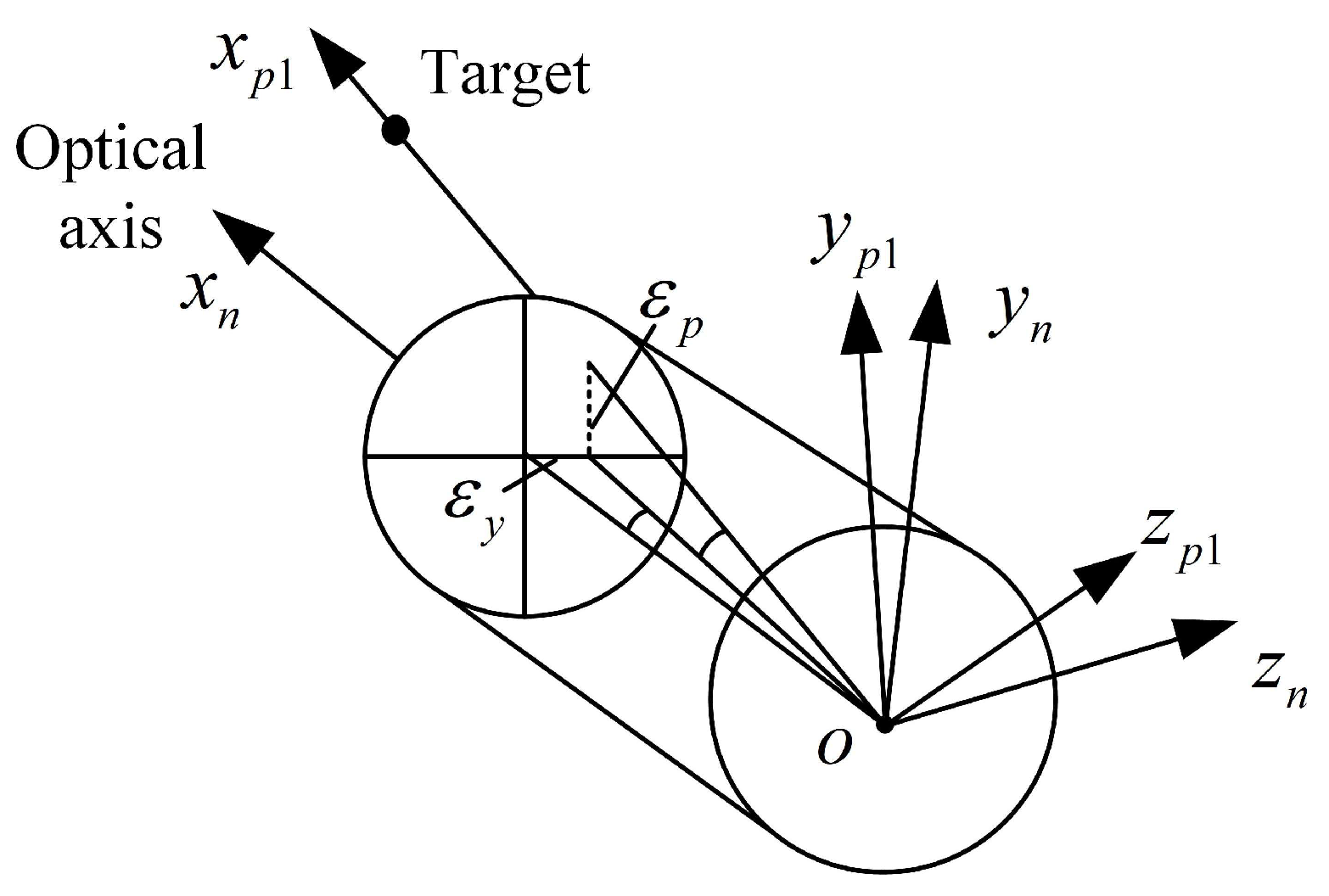
In this study, a two-axis, roll–pitch seeker was considered, as depicted in Figure 1. The outer frame of the seeker is the roll, and the inner frame is the pitch, which are, respectively, driven by the motor. The infrared detector is installed on the inner frame to detect and track the target. The error angle relation of the target in the detector’s field of view is shown in Figure 2. In order to describe the relative motion of the seeker’s inner and outer frame, aircraft body and inertial space, the coordinate used in the model of the roll–pitch seeker and the angle relationship between the coordinate systems were defined. The relationship between each coordinate system is shown in Figure 3.
Inertial coordinate o x i y i z i : The inertial coordinate system is based on the assumption that the Earth is a plane, regardless of the influence of the Earth’s rotation; the origin o selects the projection of the aircraft launch centroid on the ground; the o x i axis is the intersection line between the ballistic plane and the local horizontal plane at launch; the direction pointing to the target is positive; the o y i axis is perpendicular to the o x i axis; and upward is positive in the plumb plane. The o z i axis is perpendicular to the o x i and o y i axes and satisfies the right-hand coordinate criterion.
Body coordinate o x b y b z b : The coordinate origin o is taken at the center of mass of the aircraft; the o x b axis coincides with the longitudinal axis of the aircraft body, pointing positively to the head. The o y b axis is perpendicular to the o x b axis in the longitudinal symmetry plane of the aircraft body, and is positioned positively upward. The three axes are perpendicular to each other. The included angles between the body coordinate system and the inertial coordinate are pitch angle ϑ , yaw angle ψ and roll angle γ .
Roll frame coordinate o x w y w z w : The origin o is set in the center of the detector; the o x w axis coincides with the longitudinal axis o x b ; the o y w axis is positive in the roll frame plane and perpendicular to the o x w upward; and the o z w is perpendicular to the o x w axis and the o y w axis. The angle between the roll frame coordinate and body coordinate is the roll frame angle ϕ R .
Pitch frame coordinate o x n y n z n : The origin o is set in the center of the detector; the o x n axis coincides with the optical axis; the direction of the target is positive; the o z n axis coincides with the o z w axis; and the o z n axis is perpendicular to the o x n axis and the o z n axis. The angle between the pitch frame coordinate and the roll frame coordinate is the pitch frame angle ϕ P .
Line-of-sight coordinates o x s y s z s : The origin o is taken at the center of mass of the aircraft; the o x s axis coincides with the line of sight of the aircraft and the target is positive; the o z s axis is in the horizontal plane determined by the inertial coordinate system, perpendicular to the lox axis, and positive to the right; the o y s axis corresponds to the o x s and o z s axes. The angle between the line-of-sight coordinate and the inertial coordinate is the pitch line-of-sight angle q p and the yaw line-of-sight angle q y .
Body line-of-sight coordinate o x p 1 y p 1 z p 1 : The origin o is taken at the aircraft’s center of mass; the o x p 1 axis coincides with the line of sight of the aircraft, and points to the target positively. The o z p 1 axis is perpendicular to the axis o x p 1 in the pitch frame coordinate plane, and the o y p 1 axis is perpendicular to the o x p 1 and o z p 1 axes. The angle between the body line-of-sight coordinate and pitch frame coordinate is the pitch error angle ε p and yaw error angle ε y .
According to the above coordinate transformation relationship, the kinematics model of the roll–pitch seeker can be derived. This mainly describes the angle and angular velocity relationship between the pitch and roll frame of the seeker, the pitch frame and the aircraft body. The motion of the seeker optical axis in space is affected by the motion of the aircraft attitude and the frame, and its motion relative to the inertial space can be obtained by the composite motion of the aircraft attitude, the roll frame and the pitch frame.
The component of the attitude angular velocity relative to inertial coordinate in the body coordinate is ω b / I b : The angular velocity of the roll frame relative to the aircraft body is the component of the roll frame is ω w / b w ; the angular velocity of the pitch frame relative to the roll frame the component of the pitch frame is ω n / w n .
ω b / I b = ω b x ω b y ω b z ω w / b w = ϕ ˙ R 0 0 ω n / w n = 0 0 ϕ ˙ P
In the above formula, ω b x , ω b y and ω b z represent the measurement information of the inertial navigation of the aircraft body; ϕ ˙ R and ϕ ˙ P are the frame angular velocity of the seeker.
The angular velocity of the roll frame with respect to the inertial system and the component ω w on the roll frame can be obtained by adding the angular velocity of the roll frame with respect to the aircraft body and the component ω w / b w on the roll frame with respect to the aircraft body. With respect to the inertial system, the component ω b / I w on the roll frame is represented as ω w = ω w / b w + ω b / I w where ω b / I w is obtained from the angular velocity of the aircraft attitude relative to the inertial system in the component ω b / I b of the body system by coordinate conversion, that is, ω b / I w = C b w ω b / I b . The angular velocity of the roll frame relative to the inertial system can be written as:
ω w = ω w / b w + C b w ω b / I b             = ϕ ˙ R 0 0 + 1 0 0 0 cos ( ϕ R ) sin ( ϕ R ) 0 sin ( ϕ R ) cos ( ϕ R ) ω b x ω b y ω b z = ϕ ˙ R + ω b x ω b y cos ϕ R + ω b z sin ϕ R ω b y sin ϕ R + ω b z cos ϕ R
Similarly, the angular velocity of the pitch frame with respect to the inertial coordinates can be expressed as a projection of the pitch frame coordinates:
ω n = ω n / w n + C w n ω w           = 0 0 ϕ ˙ P + cos ϕ P sin ϕ P 0 sin ϕ P cos ϕ P 0 0 0 1 ϕ ˙ R + ω b x ω b y cos ϕ R + ω b z sin ϕ R ω b y sin ϕ R + ω b z cos ϕ R           = ϕ ˙ R cos ϕ P + ω b x cos ϕ P + ω b y cos ϕ R sin ϕ P + ω b z sin ϕ R sin ϕ P ϕ ˙ R sin ϕ P ω b x sin ϕ P + ω b y cos ϕ R cos ϕ P + ω b z sin ϕ R cos ϕ P ϕ ˙ P ω b y sin ϕ R + ω b z cos ϕ R
The roll frame only moves around the o x w axis, and the measured angular rate of the frame is:
ϕ ˙ R = ω w x ω b x
Through the combination of the angular velocity information of the roll frame and the angular velocity information of the body, the rotational angular velocity ω w x of the roll frame relative to the inertial space can be obtained so as to form the stable loop of the roll frame. The schematic diagram is shown in Figure 4. Inside the dotted frame is the model for calculating the rotation velocity of the roll frame in inertial space by mathematical solution.
As can be seen from Figure 4, the stable loop of the roll frame is only related to the roll angle rate of the aircraft body. It is not affected by the yaw and pitch velocity of the aircraft attitude and is not affected by the motion of the pitch frame.
The angular velocity of the pitch frame with respect to the inertial space can be expressed as:
ω n = ϕ ˙ R cos ϕ P + ω b x cos ϕ P + ω b y cos ϕ R sin ϕ P + ω b z sin ϕ R sin ϕ P ϕ ˙ R sin ϕ P ω b x sin ϕ P + ω b y cos ϕ R cos ϕ P + ω b z sin ϕ R cos ϕ P ϕ ˙ P ω b y sin ϕ R + ω b z cos ϕ R
The pitch frame only has movement around the o z n axis, and its measurable pitch frame angle rate is:
ϕ ˙ P = ω n z ( ω b y sin ϕ R + ω b z cos ϕ R )
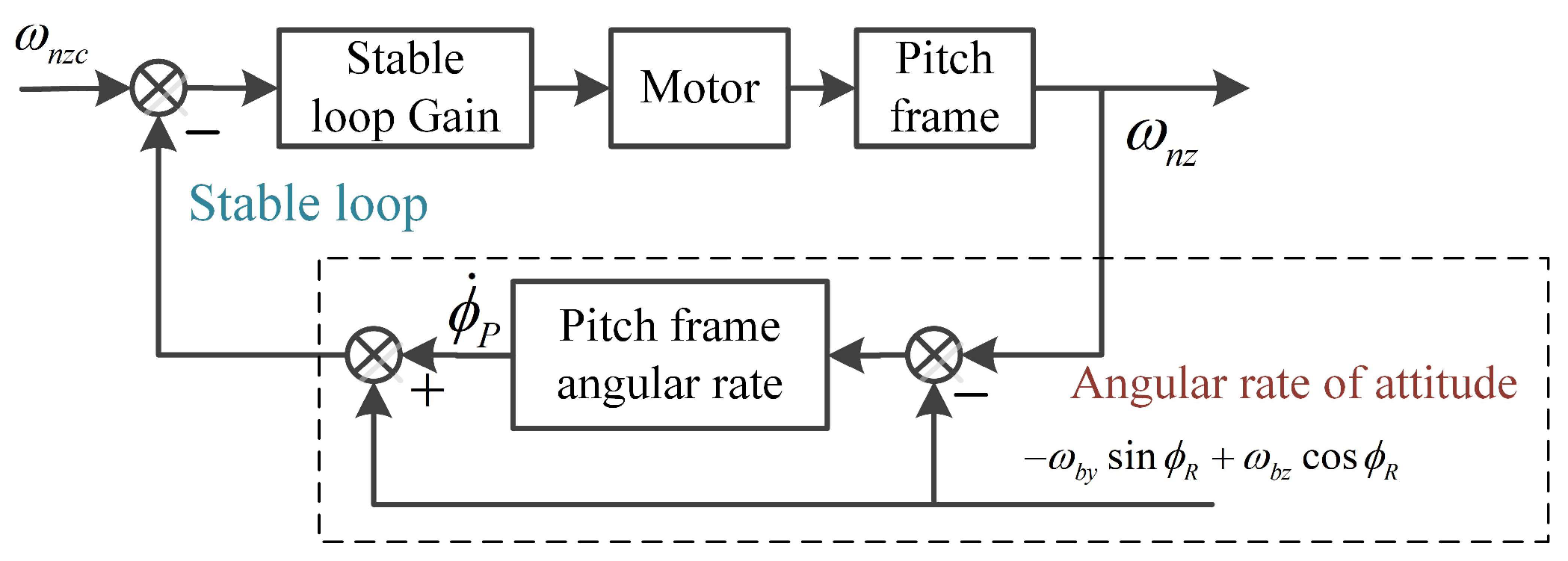
Similar to the roll frame, through the combination of pitch frame angular velocity information and attitude angular velocity information, the angular velocity of the pitch frame relative to the inertial space can be calculated, thus forming a stable loop of the pitch frame. The stability loop diagram of the pitch frame is shown in Figure 5.
As can be seen from Figure 5, the stable loop of the pitch frame is not affected by the roll angle velocity of the aircraft attitude, but is affected by the pitch angle velocity and yaw angle velocity of the aircraft attitude, and is related to the roll frame angle. Due to the coupling effect of roll channel, its stability is also affected by the angle of the roll frame.

2.2. The Conditions for a Stable Platform to Completely Isolate the Disturbance of the Aircraft Attitude

Without considering the influence of the dynamics of the stable platform, it is assumed that the frame bearing is smooth and there is no disturbance torque. The stable platform has roll frame and pitch frame, which can isolate the disturbance caused by the roll and pitch channels of the aircraft attitude, while the yaw channel has no freedom, and cannot effectively isolate the disturbance of the attitude in the yaw direction to achieve decoupling. According to the decoupling of the roll frame bearing, the roll frame bearing can effectively isolate the disturbance of the roll channel of the aircraft attitude, so that the angular velocity ω w x of the relative inertial space of the roll frame in the roll direction is 0, that is:
ϕ ˙ R + ω b x = 0
From the decoupling of the pitch frame bearing, it can be seen that the pitch frame bearing can effectively isolate the aircraft attitude disturbance in the pitch direction of the pitch frame, making the angular velocity ω n z of the relative inertial space of the pitch frame in the pitch direction 0, that is:
ϕ ˙ P ω b y sin ϕ R + ω b z cos ϕ R = 0
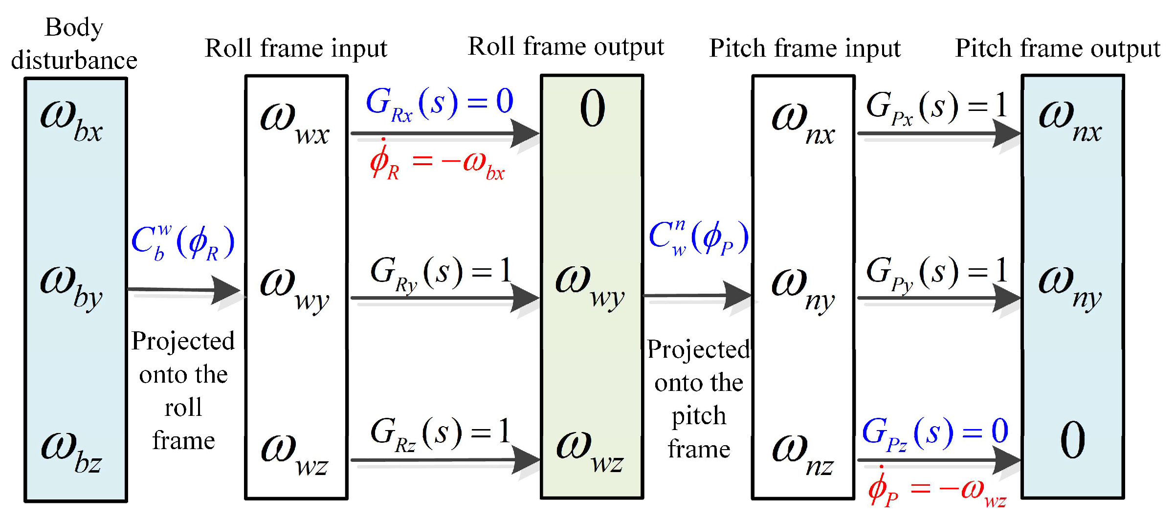
According to the bearing connection structure relationship of the roll–pitch seeker, the projection relationship diagram of the aircraft attitude disturbance on the internal frame coordinate of the seeker shown in Figure 6 can be obtained.
The above two formulae are automatically satisfied by the seeker bearing structure, without the need to add control torque.
The angular velocity of the pitch frame relative to the inertial space on the z axis is completely isolated, while the component on the y axis may not be isolated. The angular velocity of the pitch frame relative to the inertial space on the y axis is:
ω n y = ϕ ˙ R sin ϕ P ω b x sin ϕ P + ω b y cos ϕ R cos ϕ P + ω b z sin ϕ R cos ϕ P             = ϕ ˙ R + ω b x sin ϕ P + ω b y cos ϕ R + ω b z sin ϕ R cos ϕ P             = ω b y cos ϕ R + ω b z sin ϕ R cos ϕ P
When the line of sight of the seeker is stable, the line-of-sight angular velocity of the relative inertial space of the pitch frame in the z direction and the y direction is equal to 0. Since the z direction of the pitch has been decoupled through the bearing, at this time, only ω n y = 0 needs to be satisfied, which can be obtained as:
ω b y cos ϕ R + ω b z sin ϕ R cos ϕ P = 0
By solving the above formula, we can obtain:
ϕ R = a tan ω b y / ω b z or cos ϕ P = 0
When the pitch frame angle is ±90° and the pitch frame rotation axis is in the same direction as the y axis of the aircraft body, the yaw direction angular velocity of the aircraft attitude can be isolated through the bearing at this time. In addition, if the aircraft attitude has pitch angle velocity at this time, the stable platform cannot isolate the pitch angle velocity of the aircraft attitude. Only when the roll frame angle is a tan ω b y / ω b z can the stability platform isolate the disturbance of pitch direction and yaw direction at the same time to achieve complete decoupling.
In order to completely isolate the disturbance of the aircraft attitude, the roll frame angle control is needed to make the roll frame angle ϕ R of the aircraft body equal to the frame angle instruction ϕ R C required for complete decoupling. When the roll angle ϕ R of the seeker’s roll frame differs by Δ ϕ R angle from the desired decoupling direction ϕ R C , if the attitude disturbance combination velocity is set as ω , the error angle Δ ϕ R will generate the optical axis disturbance angular velocity ω Δ ϕ R on the vertical pitch frame plane. The principle diagram of the optical axis disturbance angular velocity is shown in Figure 7.
When the difference in the Δ ϕ R angle between the seeker’s roll angle ϕ R and the desired decoupling direction ϕ R C is smaller, the isolation ability of the stable platform to the aircraft attitude disturbance is stronger, and the yaw disturbance angular velocity is smaller.

3. Roll–Pitch Seeker Semi-Strap-Down Stability Control Scheme

3.1. Closed-Loop Track Principle

The detector of the seeker is fixed on the aircraft body, and the infrared radiation of the target is converted to the focal plane of the detector along the optical path through the Kuder optical path. The target position deviation obtained from the infrared image reflects the deviation information between the direction of the optical axis and the line of sight of the aircraft. The deviation information is calculated by the controller, and the control torque of the roll frame and the pitch frame is obtained to drive the frame movement. In order to reduce the deviation between the optical axis and the line of sight, the optical axis and the line of sight of the aircraft are consistent in the inertial space, and the target tracking is realized.
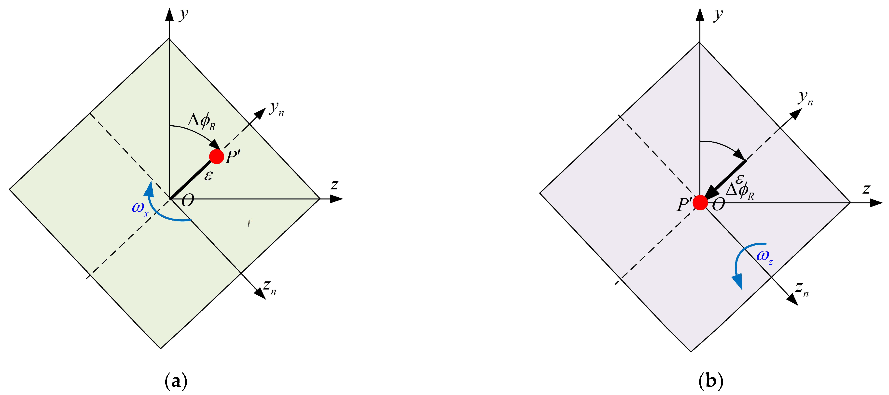
The target error angle ε p , ε y measured by the seeker detector is calculated with the current frame angle ϕ R and ϕ P , and the frame angle tracking error instructions of the pitch frame and the roll frame are Δ ϕ R and Δ ϕ P , respectively. The track error instructions are then obtained through the tracking loop correction process to obtain the input instructions of the stable loop. The projection point of the target point P on the seeker detector is P , as shown in Figure 8.
In order to track the target, it is necessary to eliminate the error angles ε p and ε y of the detector, and make P on the detector coincide with the center point O of the detector through the movement of the seeker roll frame and the pitch frame, the o x n axes of the pitch frame coordinate coincide with the o x s axes of the line of sight coordinate.
For the ε y in the direction of y n in the detector, it can be directly eliminated by control the pitch frame, while for the ε z in the direction of z n , because the seeker has no yaw frame, it cannot be directly eliminated. It is necessary to rotate the roll frame Δ ϕ R angle around the o x n axis; at this time, there is only ε = ε p 2 + ε y 2 deviation in the direction of y n on the detector. The pitch frame Δ ϕ P angles should then be rotated around o z n . P on the detector can be made to coincide with the center point o of the detector, and the movement of the target point on the detector is shown in Figure 9.
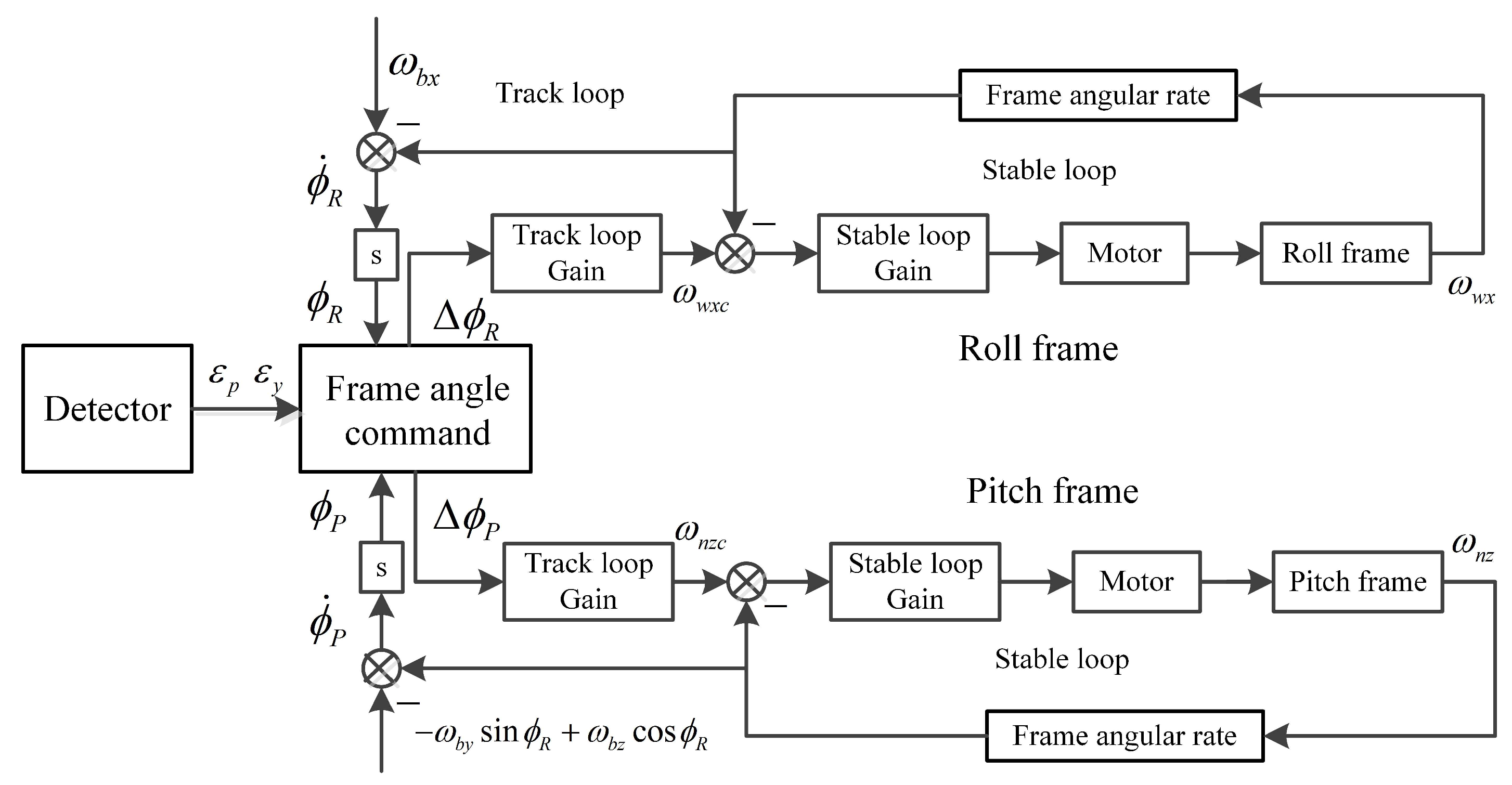
The error angle is used to control the tracking of the target and the rejecting disturbance of the aircraft attitude. The frame angle command is calculated according to the error angle measured by the detector, so as to carry out the frame control and ensure the stable tracking of the target under the disturbance of the target motion. According to the structural characteristics of the roll–pitch seeker, the semi-strap-down stable control scheme of the roll–pitch seeker is established, as shown in Figure 10.
Figure 10 shows the tracking loops of the roll frame and the pitch frame, whose feedback is the roll frame angle ϕ R and the pitch frame angle ϕ P , respectively. The tracking errors of the frame angle Δ ϕ R and Δ ϕ P are obtained by nonlinear calculation with the detector error angle ε p , ε y .
Roll frame tracking error angle Δ ϕ R by tracking loop gain is used to obtain the input command of the stable loop, and the feedback quantity of the stable loop is the roll angle velocity ω w x in the inertial space of the roll frame.
The input command of the stable loop is subtracted from the feedback angular velocity information, and the input voltage of the torque motor is obtained through stable loop gain. The frame is moved through the motor rotation so that the tracking error of the roll frame Δ ϕ R is 0. The pitch frame control is similar to the roll frame control. Finally, the tracking error Δ ϕ P of the pitch frame is 0.

3.2. Frame Tracking Instruction Calculation

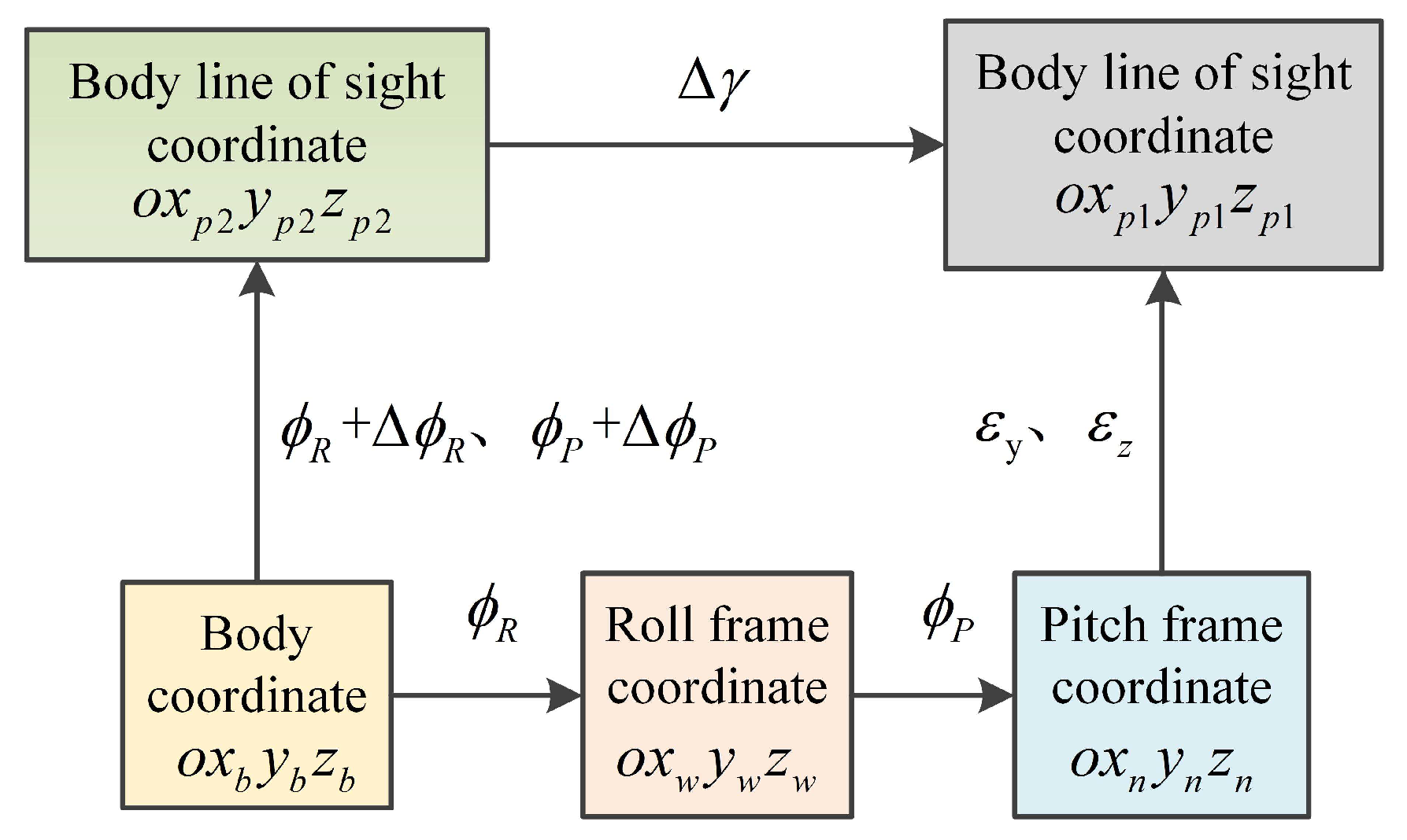
The roll frame of the seeker is a roll frame that can roll around the longitudinal axis o x b of the aircraft body; the pitch frame is a pitch frame, and the axis pitch movement can be carried out around the o z w axes of the roll frame. The detector error angles are ε p and ε y . Figure 11 shows the coordinate transformation relationship of the roll–pitch seeker.
As is shown in Figure 11, the body coordinate o x b y b z b can obtain the roll frame coordinate o x w y w z w by roll frame motion ϕ R , and the pitch frame coordinate system o x n y n z n by pitch frame motion ϕ P . The pitch frame coordinate system is converted to the body line-of-sight coordinate o x p 1 y p 1 z p 1 by rotating the detector pitch deviation ε p and yaw deviation ε y , and the axis o x p 1 of the coordinate system points to the target.
Therefore, the transformation process from the aircraft body coordinate to the body line-of-sight coordinate o x p 1 y p 1 z p 1 can be expressed as:
x p 1 y p 1 z p 1 = C n p C w n C b w x b y b z b
Similarly, the body coordinate can also rotate the roll frame angles ϕ R + Δ ϕ R and pitch frame angle ϕ P + Δ ϕ P to obtain the body line-of-sight coordinate o x p 2 y p 2 z p 2 , and the o x p 2 axes of the body line-of-sight coordinate 2 point to the target.
x s l y s l z s l = L z ( ϕ P + Δ ϕ P ) L x ( ϕ R + Δ ϕ R ) x b y b z b                     = cos ( ϕ P + Δ ϕ P ) sin ( ϕ P + Δ ϕ P ) 0 sin ( ϕ P + Δ ϕ P ) cos ( ϕ P + Δ ϕ P ) 0 0 0 1 1 0 0 0 cos ( ϕ R + Δ ϕ R ) sin ( ϕ R + Δ ϕ R ) 0 sin ( ϕ R + Δ ϕ R ) cos ( ϕ R + Δ ϕ R ) x b y b z b
The o x p 1 axes and o x p 2 axes both point to the target, and there is a line-of-sight roll angle Δ γ difference between the two coordinates. Then, the transformation matrix C n p C w n C b w from the body coordinate system to the body line-of-sight coordinate system 1 and the first line elements of the transformation matrix L z ( ϕ P + Δ ϕ P ) L x ( ϕ R + Δ ϕ R ) from the body coordinate system to the coordinate system o x p 2 y p 2 z p 2 correspond to each other, and we can obtain:
cos ( ϕ P + Δ ϕ P ) = cos ε p cos ε y cos ϕ P sin ε p sin ϕ P sin ( ϕ P + Δ ϕ P ) cos ( ϕ R + Δ ϕ R ) = cos ε p cos ε y   sin ϕ P cos ϕ R + sin ε p   cos ϕ P cos ϕ R + cos ε p sin ε y   sin ϕ R sin ( ϕ P + Δ ϕ P ) sin ( ϕ R + Δ ϕ R ) = cos ε p cos ε y   sin ϕ P sin ϕ R + sin ε p   cos ϕ P sin ϕ R cos ε p sin ε y cos ϕ R
By solving the above equations of motion, we can obtain the pitch frame error angle calculation formula as:
Δ ϕ P = ± c o s 1 ( cos ε p cos ε y cos ϕ P sin ε p sin ϕ P ) ϕ P
In the above Equation (14), if ε p < 0 and ϕ P > ε p , or ε p 0 and ϕ P ε p , the inverse cosine function is given a positive sign in front, and a negative sign in all other conditions.
The formula for calculating the error angle of the roll frame is:
Δ ϕ R = tan 1 cos ε p sin ε y cos ε p cos ε y   sin ϕ P + sin ε p   cos ϕ P
The conditions of use in the above formula: when ϕ P 0 or ε p 0 . When ϕ P = 0 , ε p = 0 , if ε y = 0 , then Δ ϕ R = 0 ; If ε y > 0 , then Δ ϕ R = 90 ; If ε y < 0 , then Δ ϕ R = 90 .
It can be seen from the calculation formula of the error angle of the pitch frame and the roll frame that the current roll frame angle ϕ R has no influence on the calculation of the frame error angle, and the influence of the roll frame angle is reflected in the detector error angles ε p and ε y . According to the nature of the arctangent trigonometric function, the range of error angle Δ ϕ R of the roll frame is 90 Δ ϕ R 90 . By calculating the error angles of pitch frame and roll frame, a two-frame servo control can be carried out to eliminate the detector error angles ε p and ε y .

3.3. Frame Control DRR

The platform pitch–yaw seeker eliminates the error angle in the pitch direction through the motion of the pitch frame, and the yaw direction error angle of the detector through the motion of the yaw frame. There is a certain numerical coupling between the two channel instructions, but they are relatively independent in the rotation process. At the same time, an angle rate gyro is installed on the inner frame, which can output the line-of-sight angle rate. Therefore, for the platform seeker, the DRR can be defined by the extra line-of-sight angle rate caused by the aircraft attitude disturbance, while the roll–pitch seeker can only differentiate the frame angle measured by the frame sensor to obtain the frame angle rate. For the roll–pitch seeker, the DRR can be defined as:
R r / p = ω w x / n z ω b x / b z × 100 %
Among them, R r / p is the DRR of the roll frame and pitch frame, and ω w x / n z is the rotational angular velocity of the two frames relative to the inertial space caused by the disturbance of the aircraft attitude ω b x / b z .
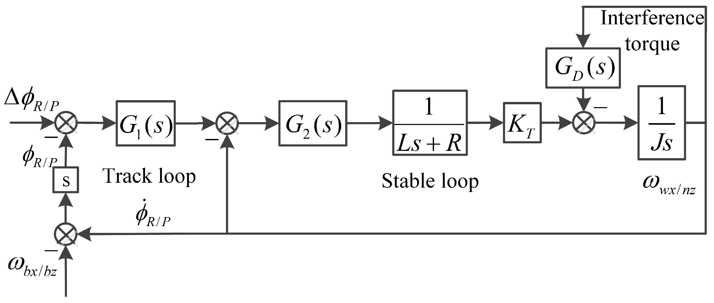
The roll frame and pitch frame control model are shown in Figure 12.
The interference torque affecting the DRR mainly includes the spring torque and the damping torque, so that the spring torque coefficient is K n , and the damping torque coefficient is K ω . This is proportional to the spring torque and the viscous damping torque. The spring torque model G D ( s ) = K n / s and damping torque model G D ( s ) = K ω are included in the block diagram of Figure 12, and the DRR of the frame can be derived as follows:
R r / p K n = K n ( L s + R ) J L s 3 + J R s 2 + G 2 ( s ) K T + K n L s + K n R + G 1 ( s ) G 2 ( s ) K T R r / p K ω = K ω L s 2 + K ω R s J L s 3 + ( K ω L + J R ) s 2 + ( G 2 ( s ) K T + K ω R ) s + G 1 ( s ) G 2 ( s ) K T
The control parameters of the roll and pitch frame are shown in Table 1. The frame track loop G 1 ( s ) takes only the scale term G1, and the stable loop G 2 ( s ) takes only the scale term G2.
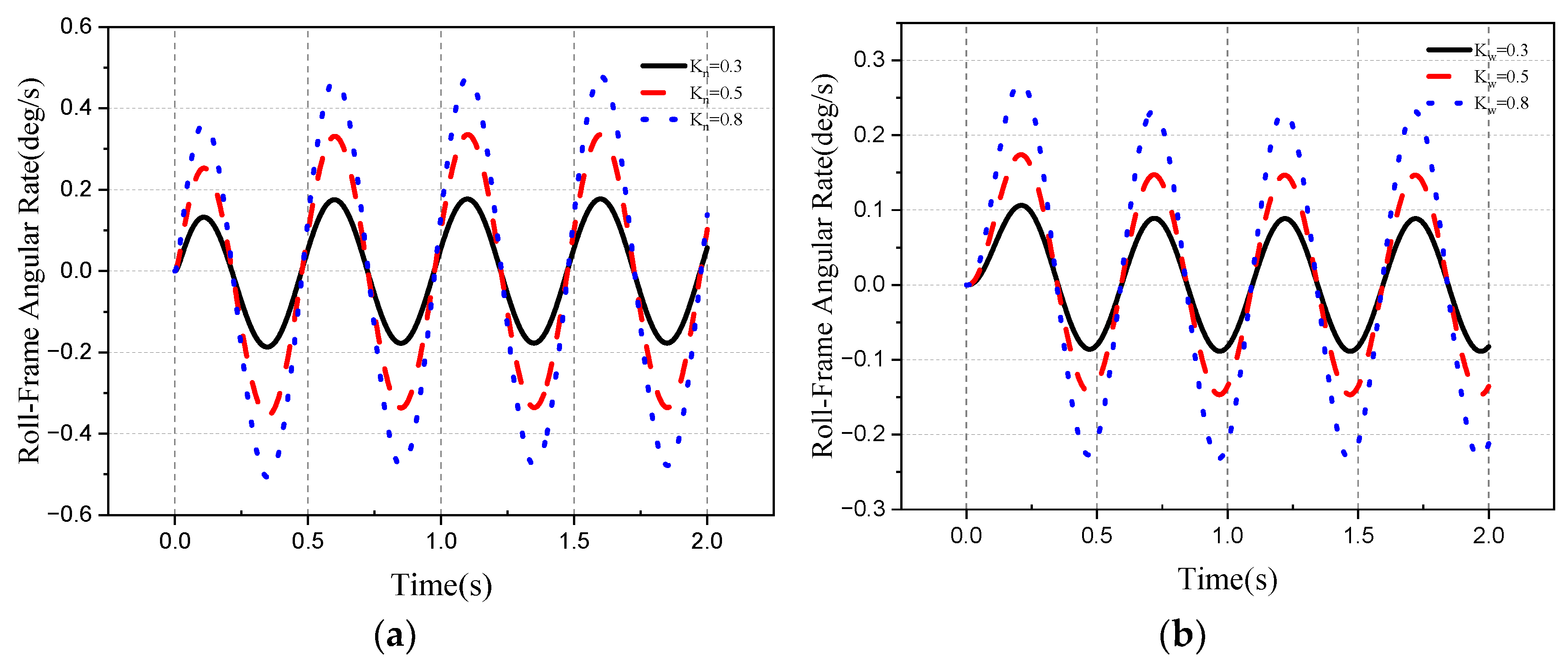
If the input of the roll error angle of the roll frame is 0 and the roll disturbance of the aircraft attitude is a sinusoidal motion with an amplitude of 5°/s and a frequency of 2 Hz, the DRR generated by the interference torque is related to the form and coefficient of the interference torque. Then, the roll angle velocity ω w x of the roll frame relative to inertial space under the influence of interference torque can be obtained through simulation, as shown in Figure 13.
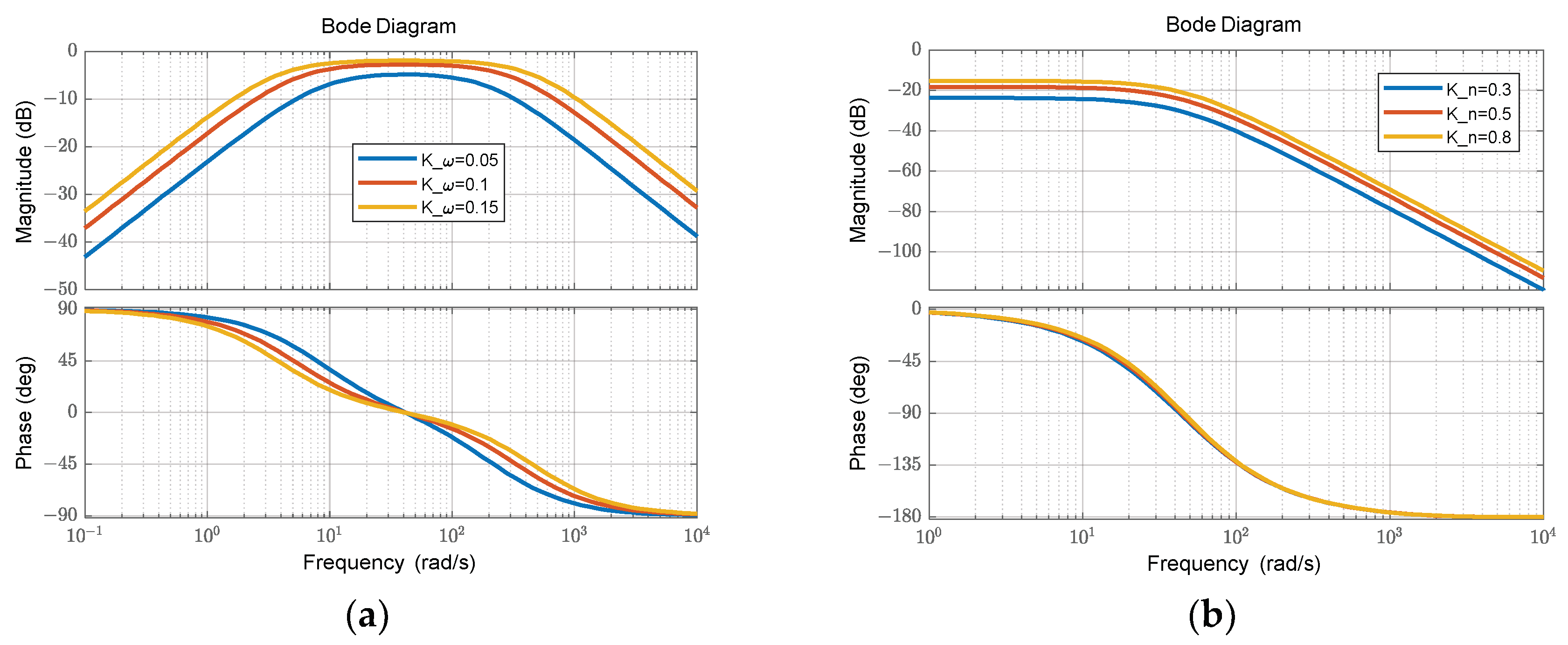
As can be seen from Figure 13, the DRR generated by damping torque is sensitive to the change in its coefficient K ω . When K ω is 0.05, 0.1 and 0.15, the DRR is 3.5%, 6.6% and 9.5%, respectively. When the spring torque coefficient K n is 0.3, 0.5 and 0.8, the DRR is 2.1%, 3.5% and 5.4%, respectively. From the amplitude–frequency characteristics of Figure 14, it can be seen that the isolation interference factor of the seeker is damping torque, which has a greater impact on the aircraft attitude disturbance above 10 Hz, and the spring torque has a greater impact on the seeker when the aircraft attitude disturbance frequency is 0.1~10 Hz. The initial phase of the DRR transfer function of the two is 90° and 0°, so the isolation parasitic loop can be considered as positive feedback. The law of the pitch frame DRR is similar to that of the roll frame; thus, it will not be repeated here.

4. Simulation

4.1. Stability of the Roll–Pitch Seeker

According to the disturbance analysis of the isolated aircraft attitude and the control scheme of the stabilized platform, it can be seen that the seeker achieves platform stability through semi-strapping. In addition, it can isolate the angular velocity interference of the roll and pitch of the aircraft attitude through the movement of the roll frame and pitch frame. For the yaw angular velocity, complete decoupling can be realized only when the angle of the roll frame is satisfied, and the velocity direction of the pitch and yaw disturbance of the aircraft attitude is the same. The roll seeker needs to isolate the aircraft attitude disturbance by roll frame angle, in which case, the two frames need to cooperate in control. This section will analyze the stability ability of the platform under different conditions. MATLAB/Simulink on the computer (AMD, Ryzen-7 4800 H, 2.9 GHz, RAM, 16.0 GB) was used to simulate and analyze the stability of the platform under different conditions.
The simplified frame control model was selected. The bandwidth of the tracking loop of the pitch frame control system was selected as 2 Hz, and the gain of the stable loop was 30 Hz. At the initial time, the seeker’s optical axis pointed to the target and the target was fixed. The influence of the DRR of the roll seeker on the motion of the optical axis under the disturbance of the aircraft attitude was analyzed.
The yaw direction disturbance of the aircraft attitude is:
ϑ = 0 φ = 0 γ = 0 ω b x = 0 / s ω b y = sin 4 π t / s ω b z = 0 / s
When the initial attitude angle of the aircraft attitude is 0 and the yaw direction of the aircraft attitude is sin 4 π t / s , the initial roll frame angle and pitch frame angle of the seeker are ϕ R = 0 and ϕ P = 0 . Adding spring and damping interference torque to the roll frame, the damping torque coefficient K ω was 0.05, 0.1, 0.15, and the spring torque coefficient K n was 0.3, 0.5, 0.8. According to the condition that the roll seeker completely isolates the disturbance of the aircraft attitude, the required roll frame angle is:
ϕ R C = a tan ω b y / ω b z = 90
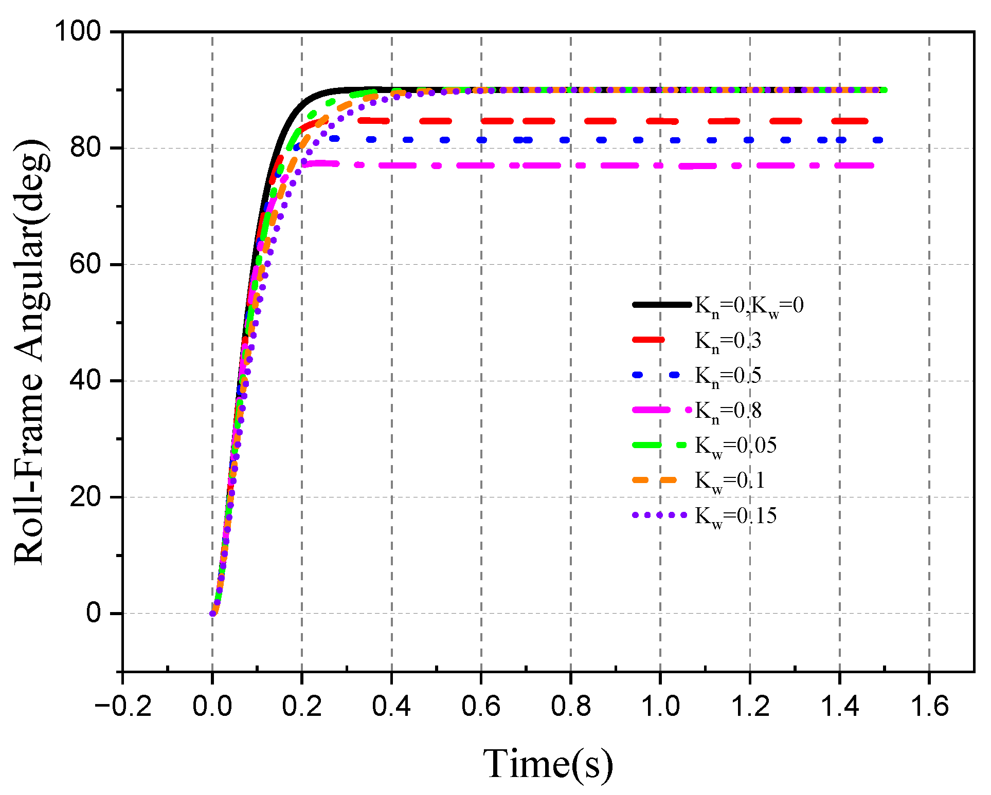
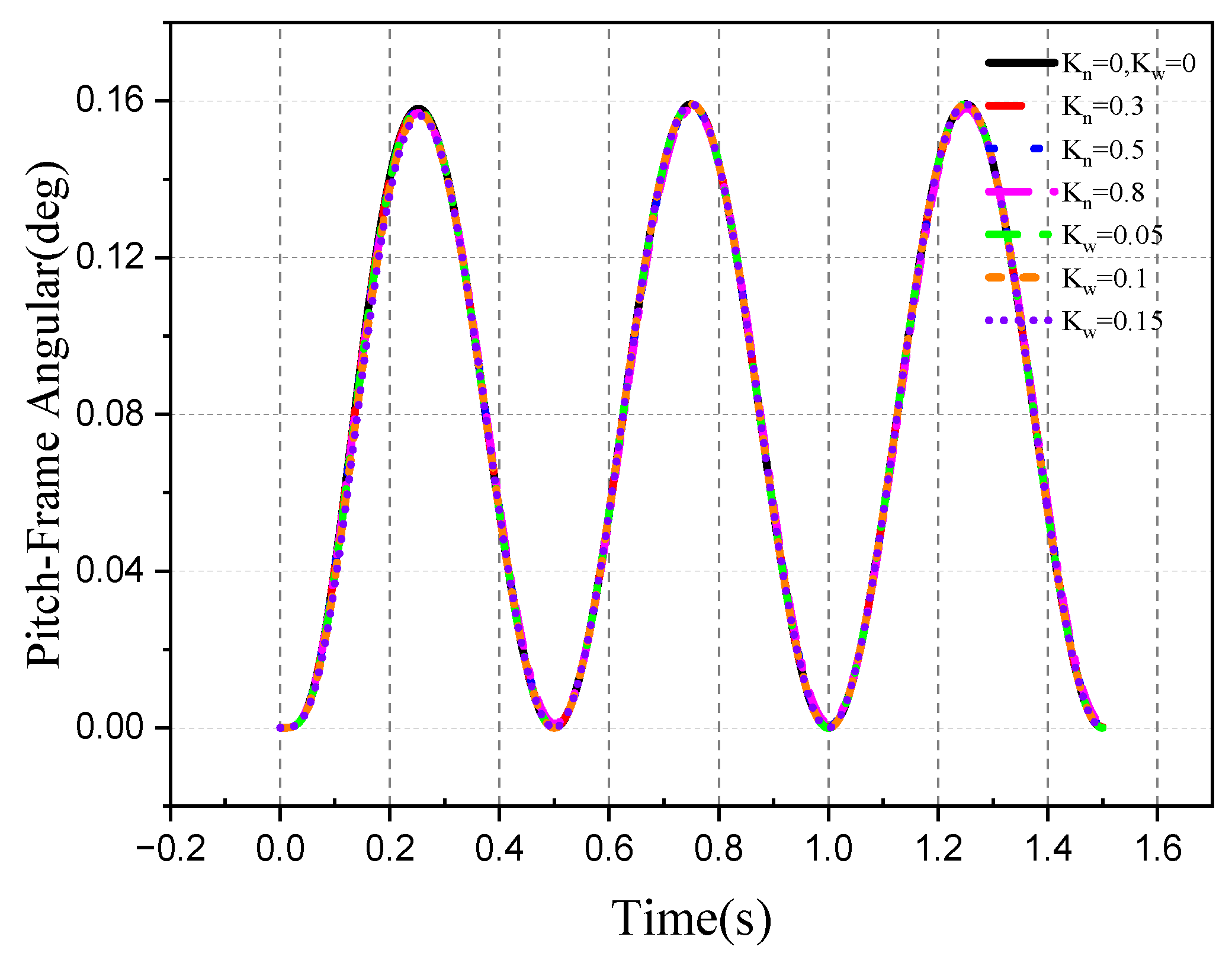
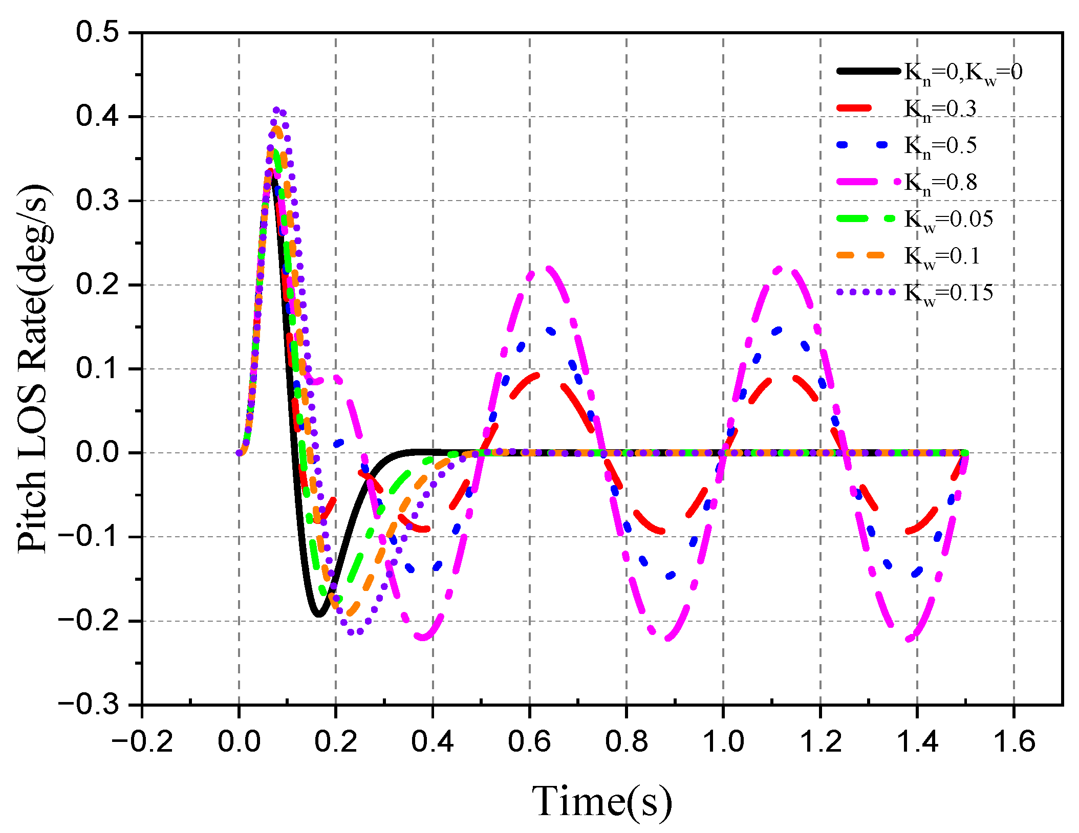
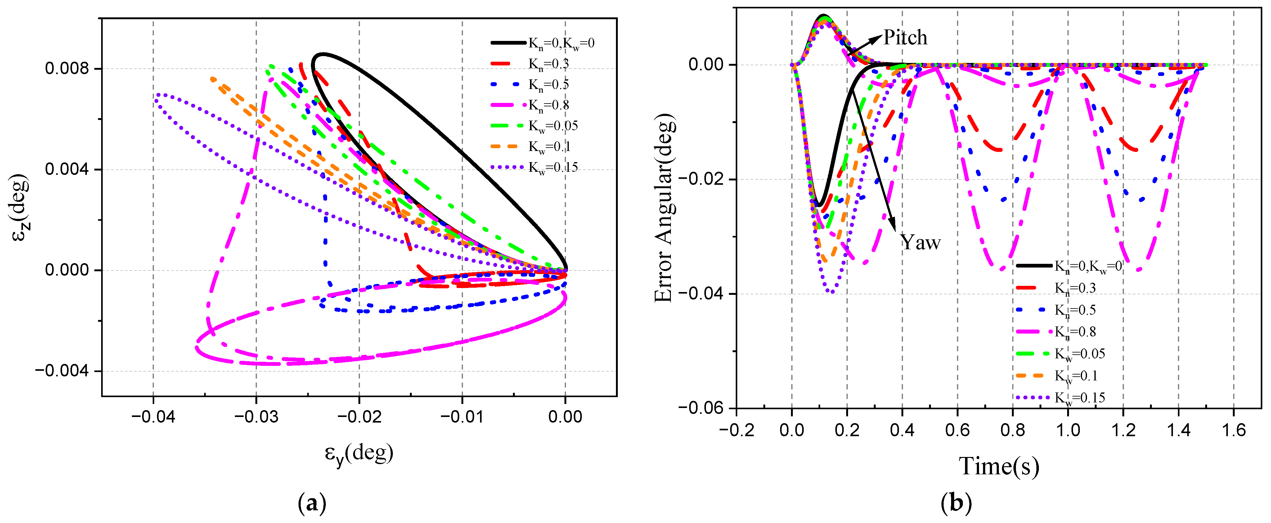
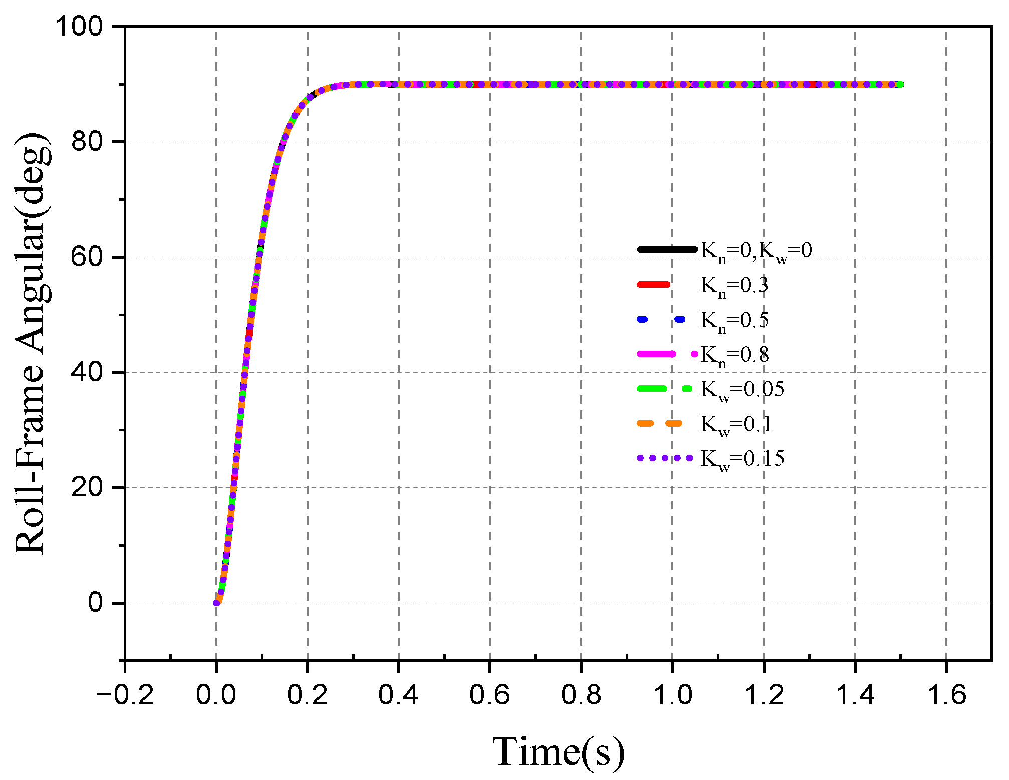
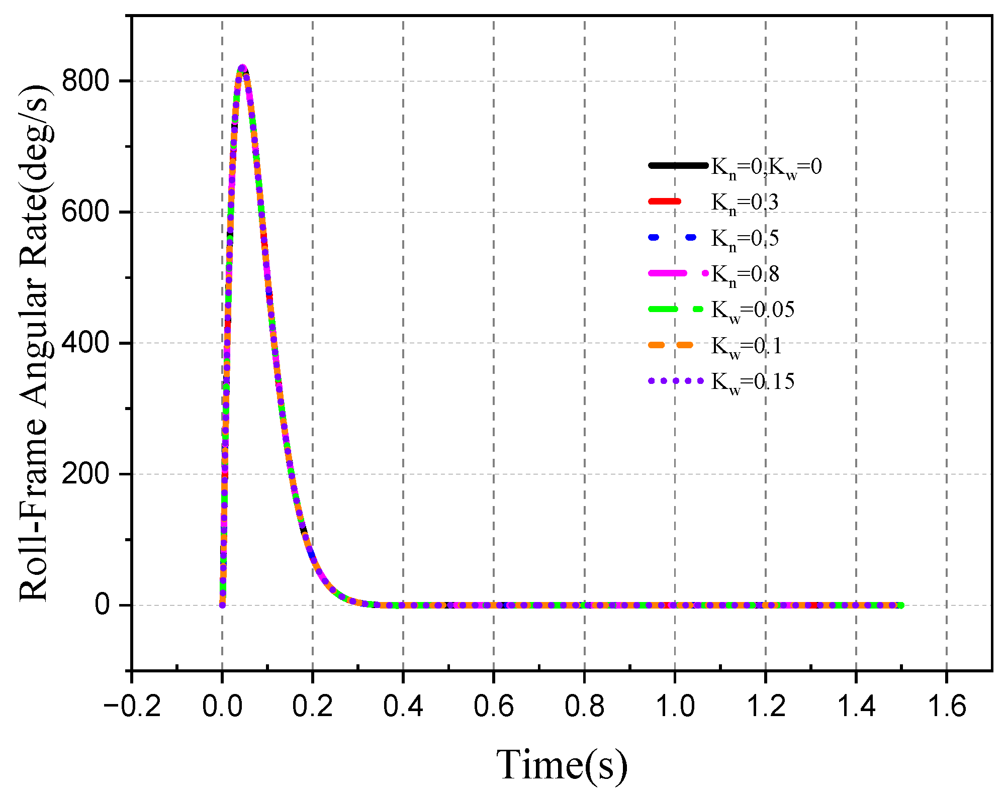
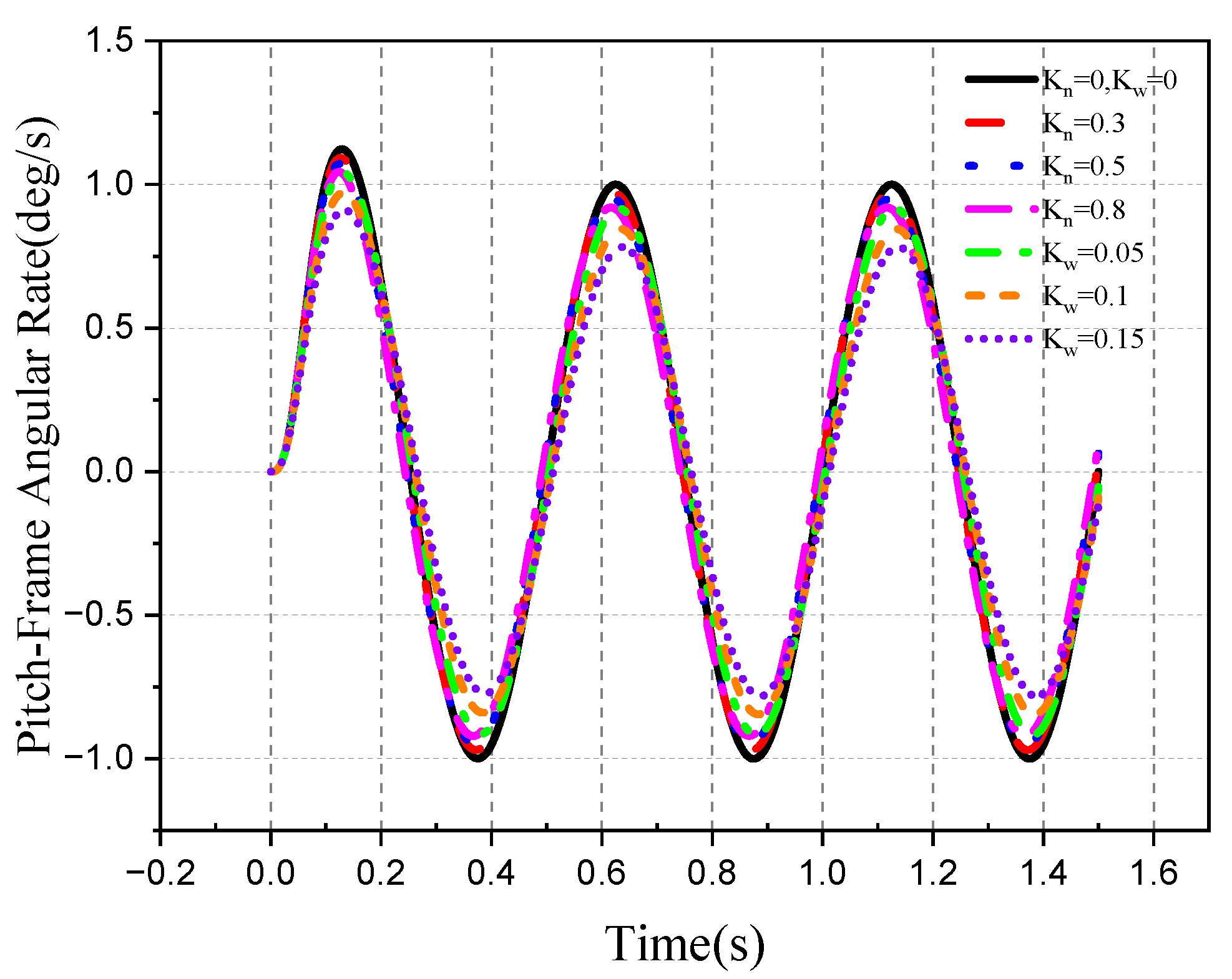
The roll frame needs to be rolled 90° to completely isolate the aircraft attitude disturbance. The roll–pitch seeker optical axis and frame motion curves under different DRR models are shown in Figure 15, Figure 16, Figure 17, Figure 18, Figure 19, Figure 20 and Figure 21.
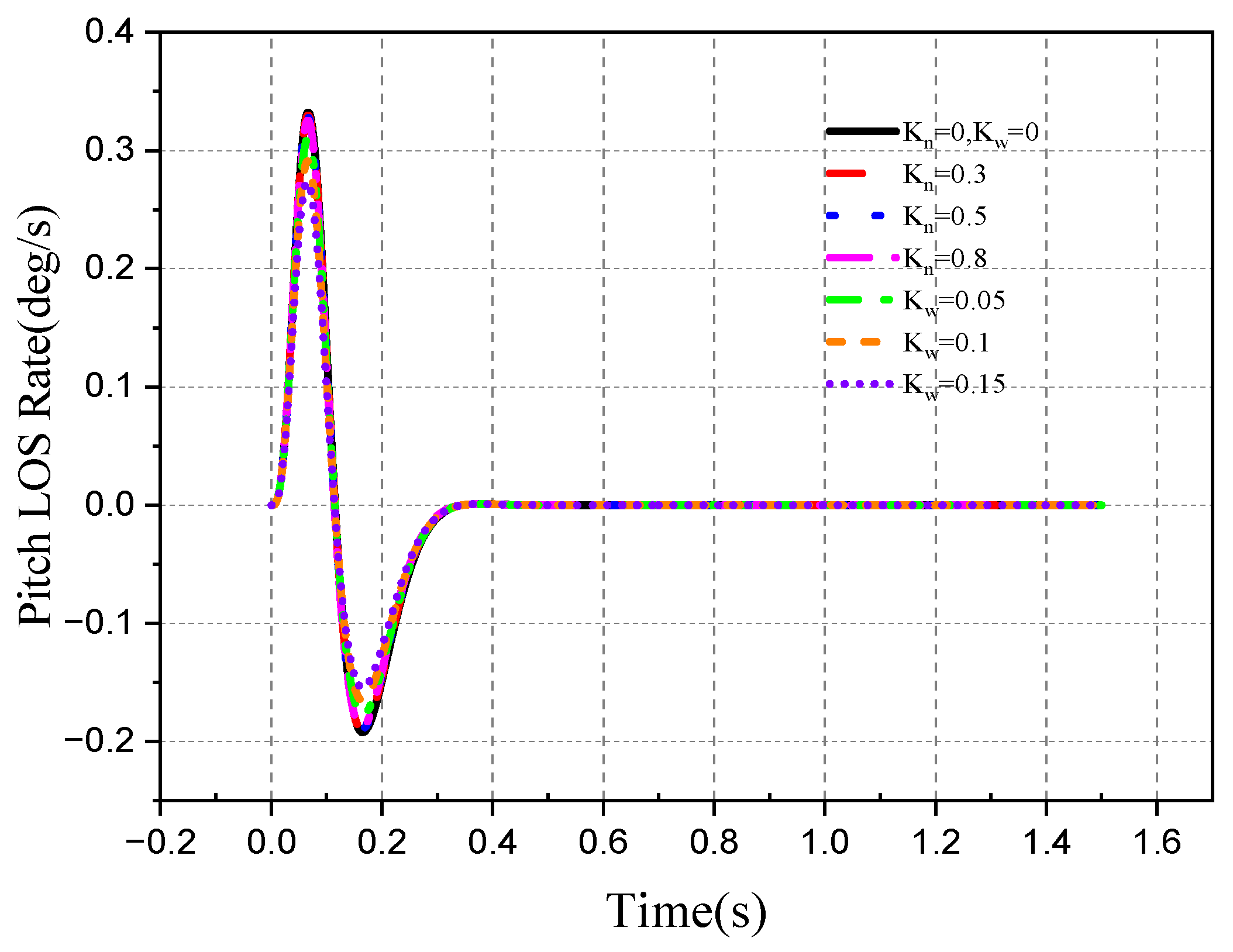
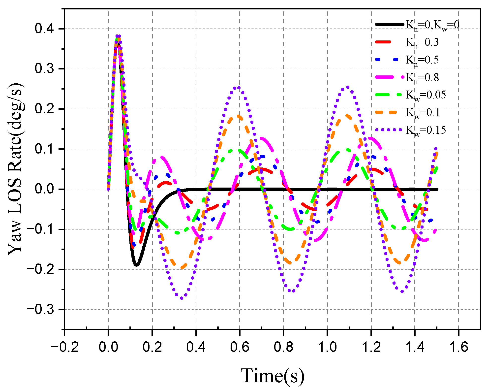
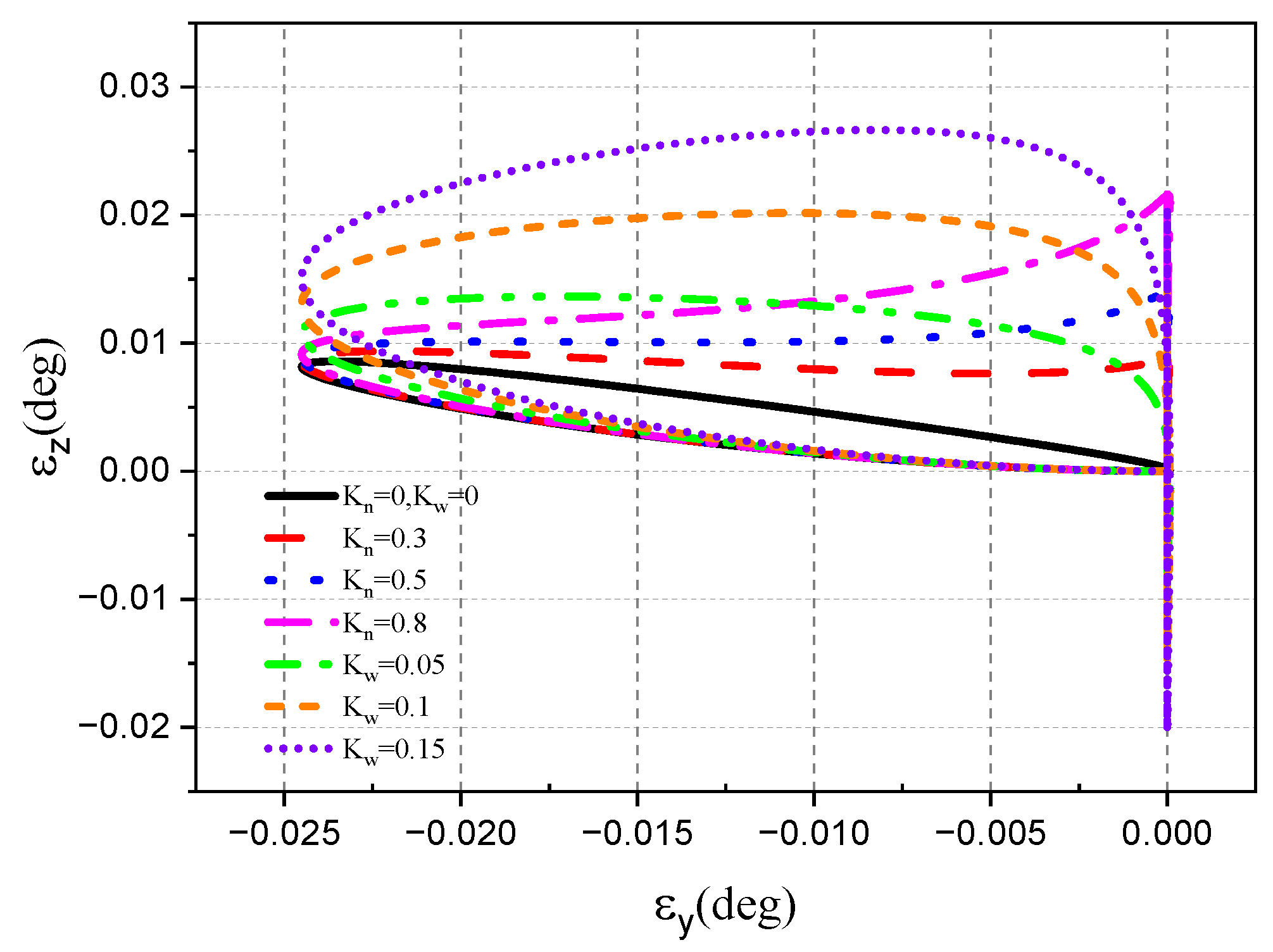
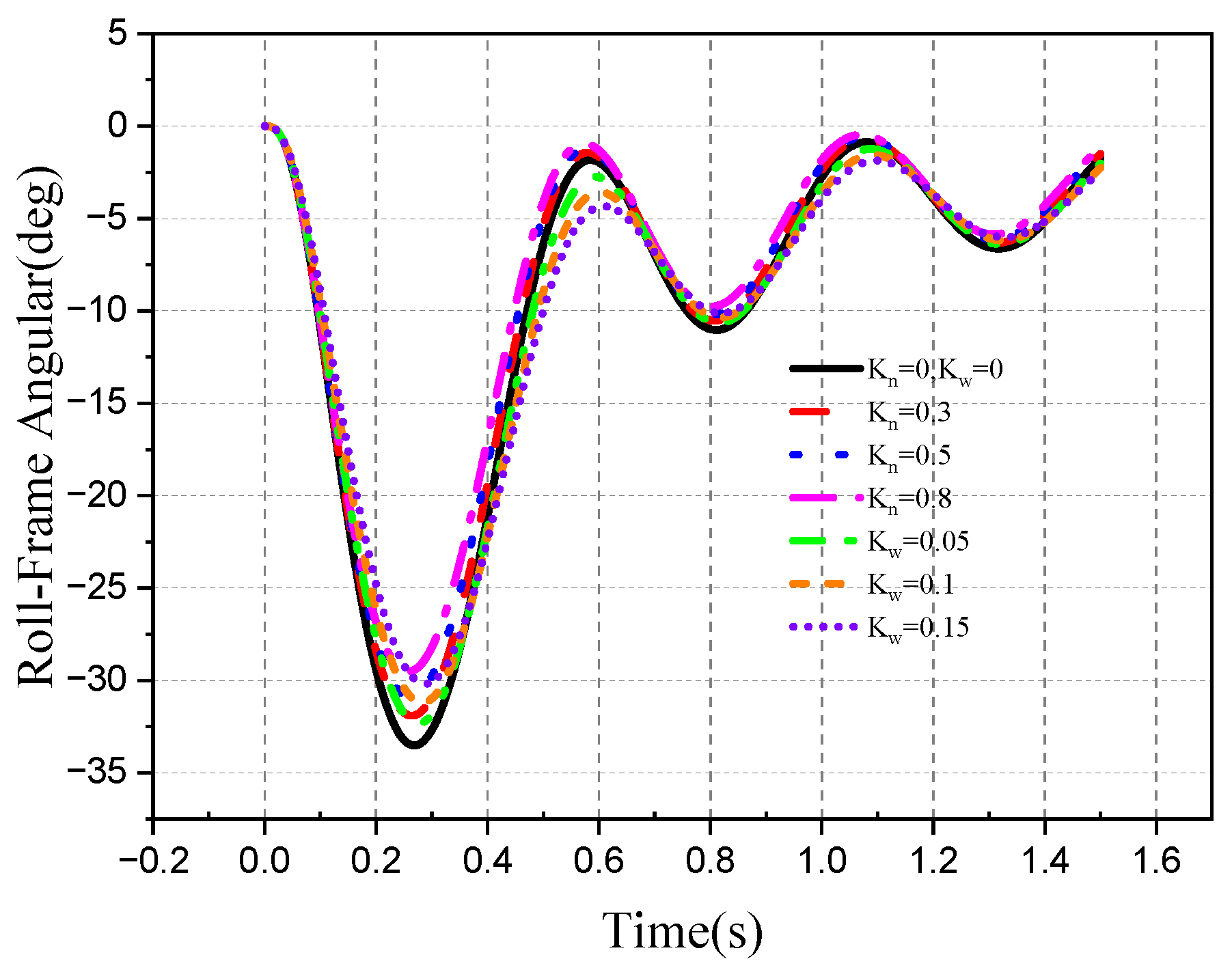
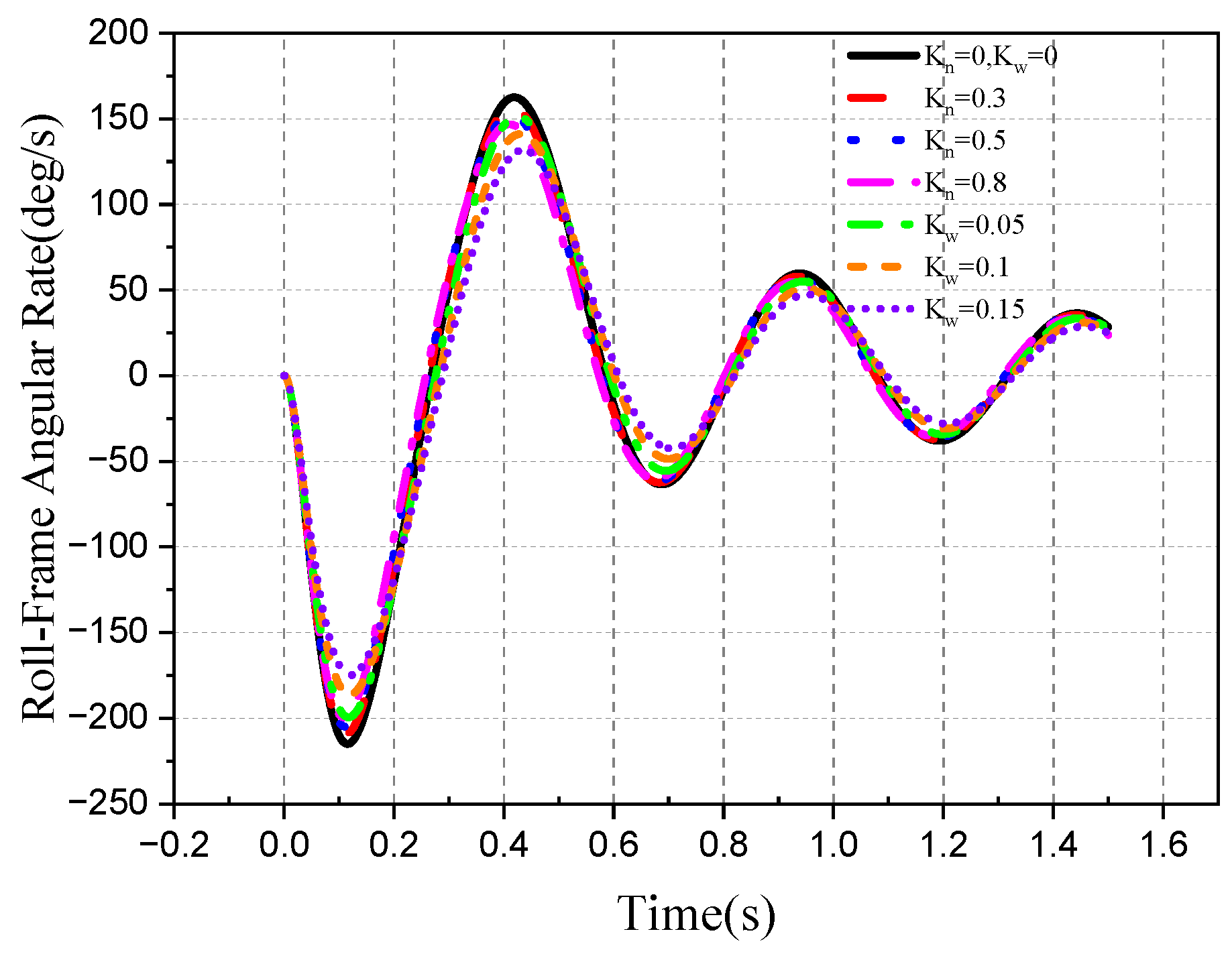
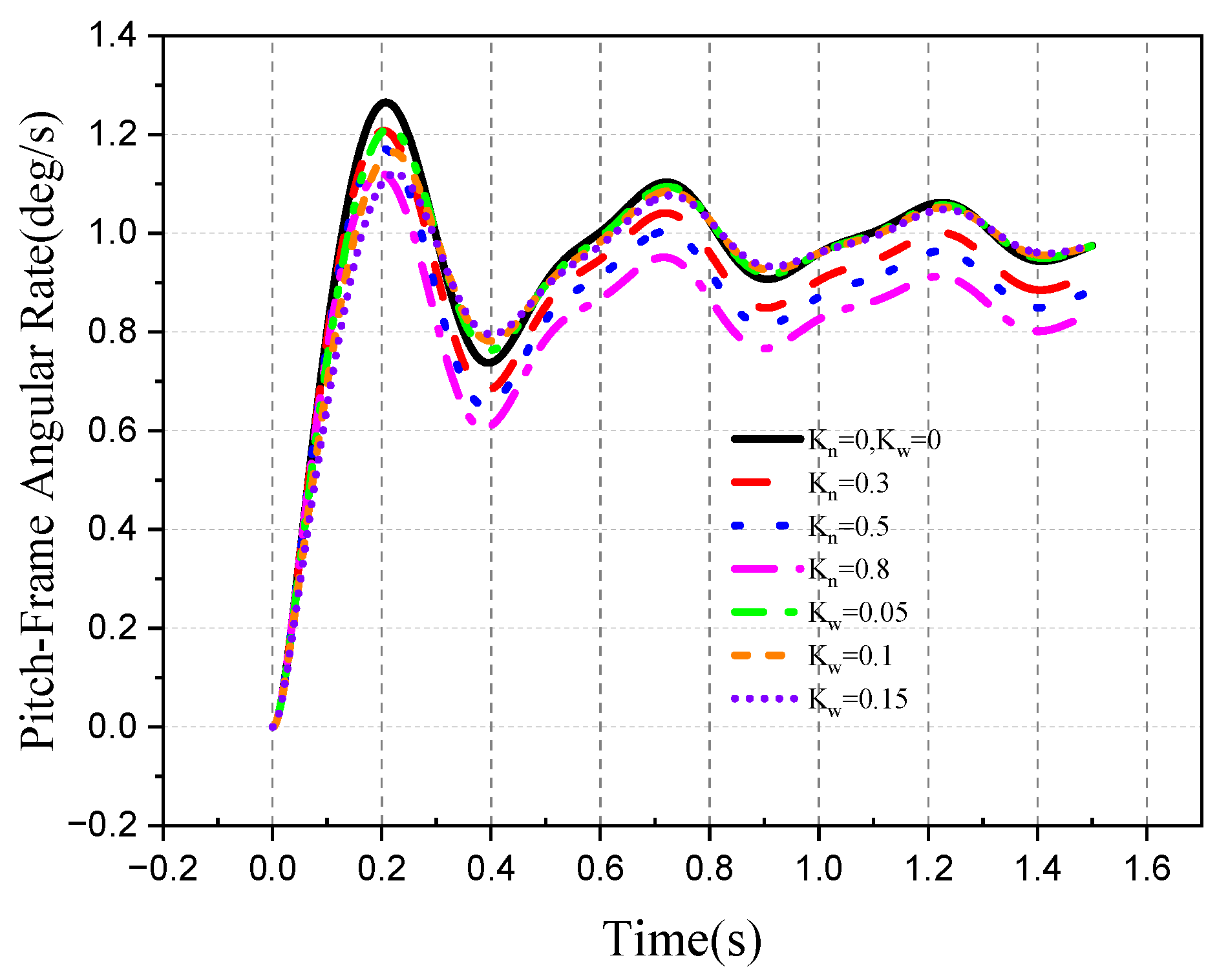
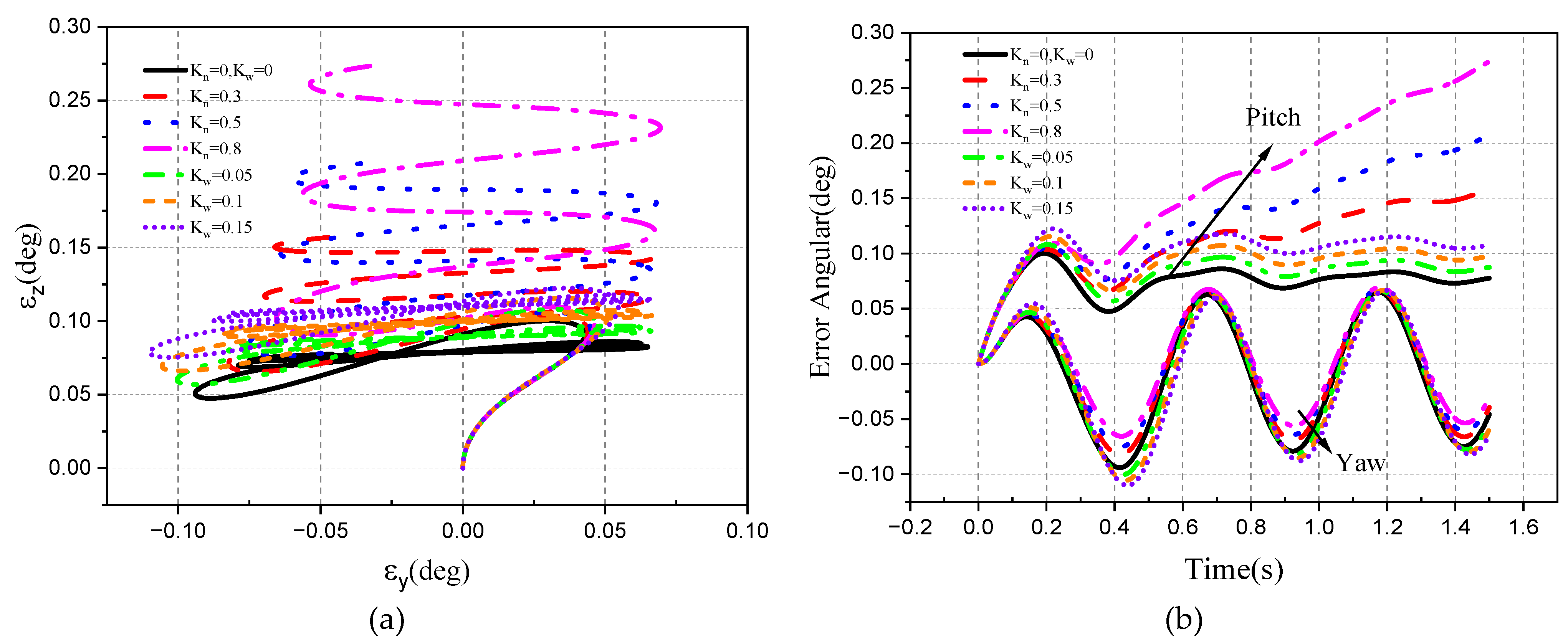
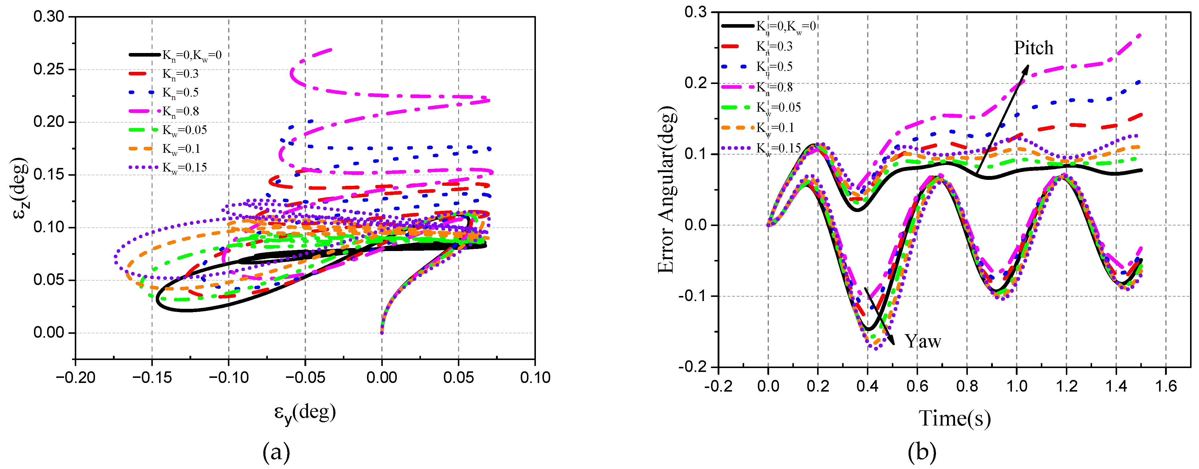
It can be seen from the simulation results that under the influence of interference torque, the roll frame produces an extra frame angle rate and the roll frame angle deviation. With the increase in K n , the roll frame angle error is larger, while under the condition of low-frequency rotation, the K ω has little influence on the roll frame angle. Under normal circumstances, when the seeker’s roll frame angle is 90°, it can completely isolate the yaw angular velocity disturbance of the attitude and ensure the stability of the optical axis in inertial space. However, K n = 0.8 has the greatest effect on the DRR; an additional pitch direction component will be generated when the pitch frame isolates the yaw direction disturbance. With the increase in the spring moment, the deviation in the pitch line-of-sight angle rate is larger, and the yaw direction cannot completely isolate the disturbance of aircraft attitude, resulting in a line-of-sight angle rate error. The detector pitch and yaw error will increase under the interference of the spring moment.
The roll frame Is the Ideal model, and the disturbance torque model Is added to the pitch frame. Under the above conditions, the simulation results are shown in Figure 22, Figure 23, Figure 24, Figure 25, Figure 26, Figure 27 and Figure 28.
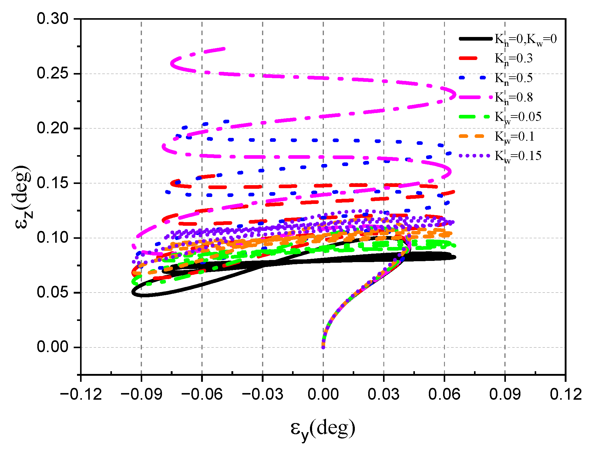
As can be seen from the simulation results, the roll frame can accurately track the control instruction to turn to 90°, and there is a coupling angular velocity in the pitch direction of the optical axis during the roll process. The transition time of the roll to 90° is very short, and the pitch angle velocity of the optical axis caused by the disturbance of the attitude is quickly stabilized at 0°. Under the interference of damping torque, the DRR increases with the increase in K ω . In addition, the line-of-sight angle rate in the yaw direction of the optical axis coupled with the attitude disturbance information will also increase. This results in the detector error oscillating back and forth in the pitch direction. The DRR generated by the spring torque has little influence on the pitch line-of-sight angle rate and detector error under the high-frequency disturbance.
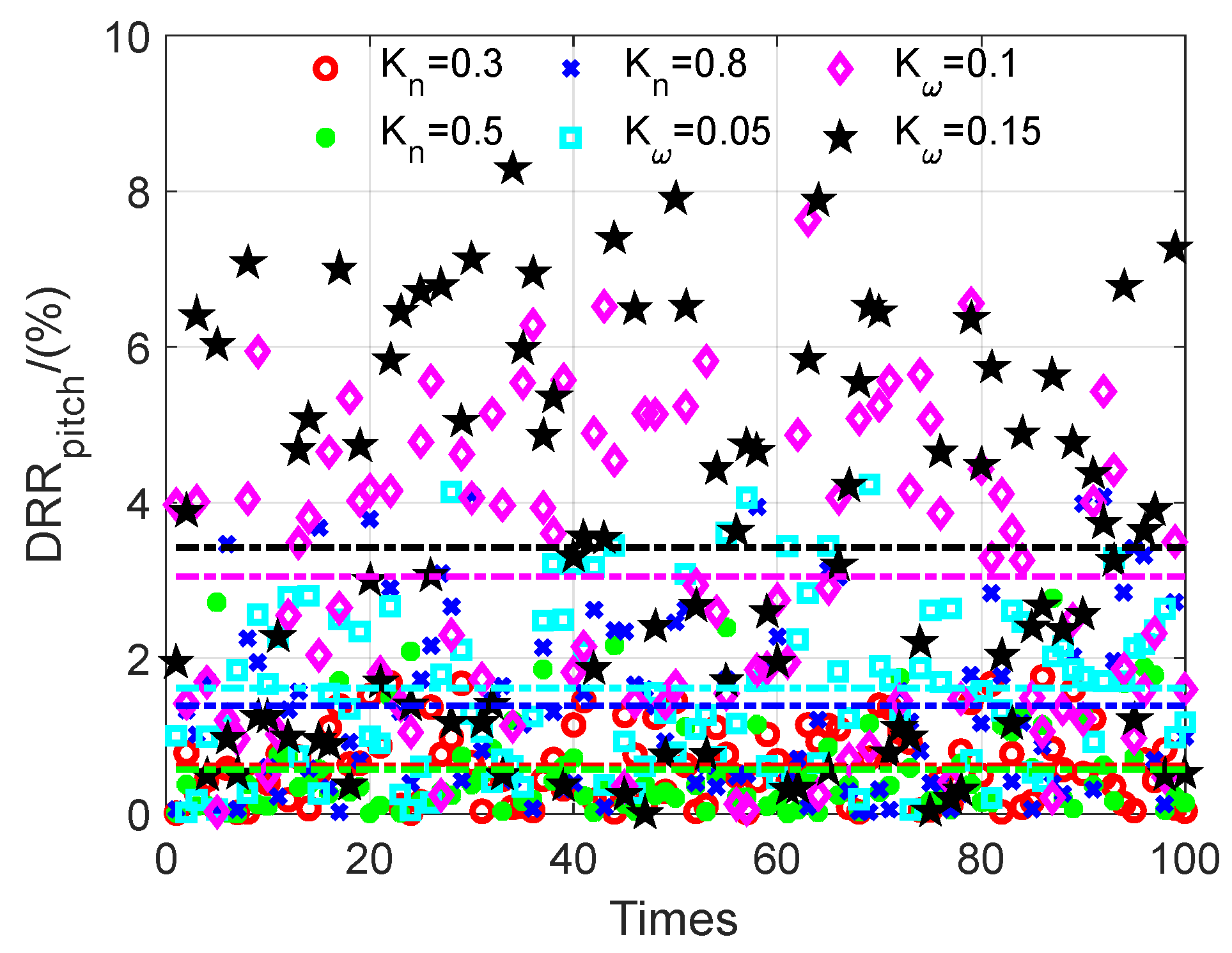
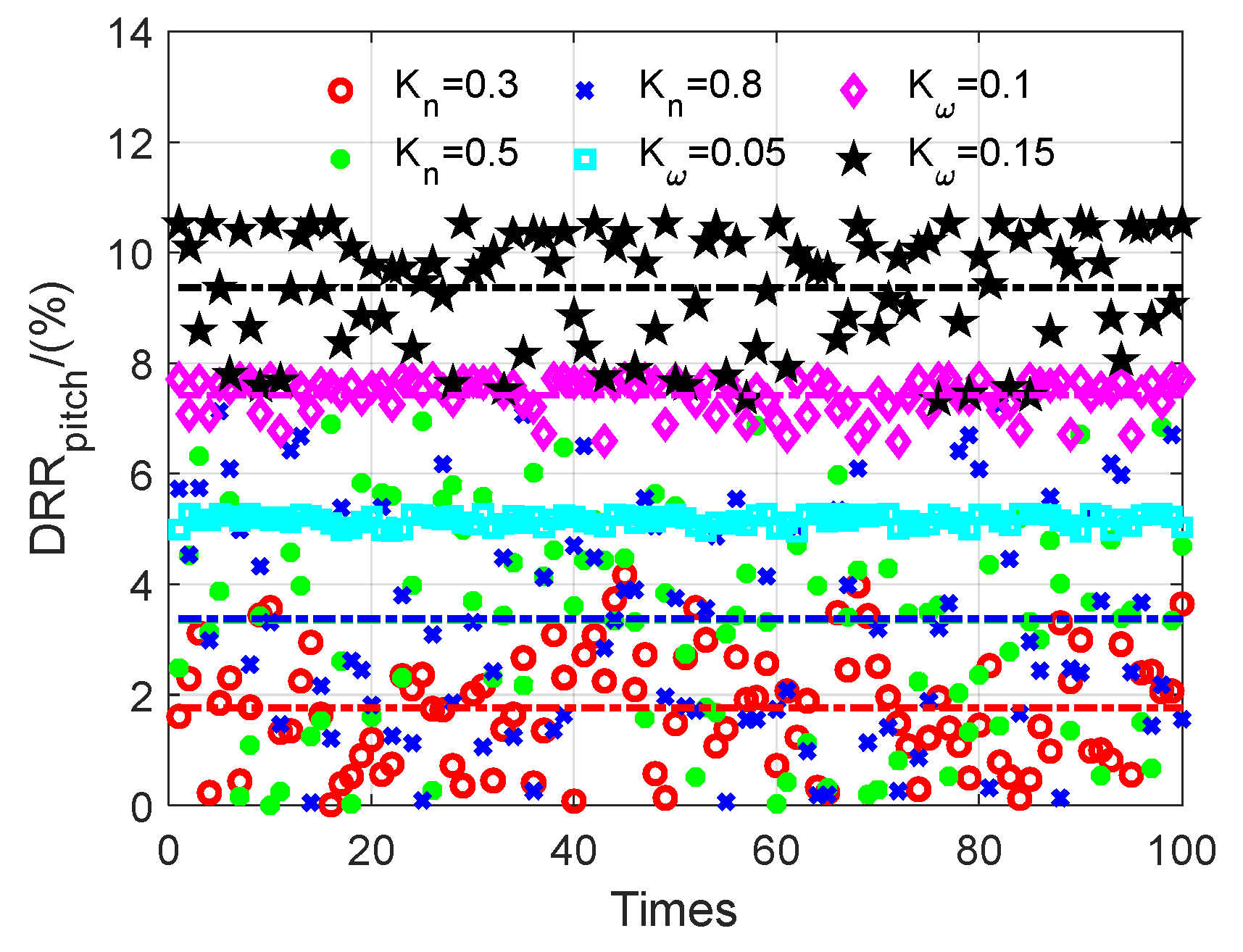
Without changing the parameters of the track and stable loop gain of the two frames of the seeker, it is assumed that the seeker model parameters in Table 1 are perturbed in the range of ±20%. To compare the robustness of the seeker under different interference parameters, 100 Monte Carlo simulations are conducted under each working condition. The simulation results of the DRR of the seeker pitch frame are shown in Figure 29.
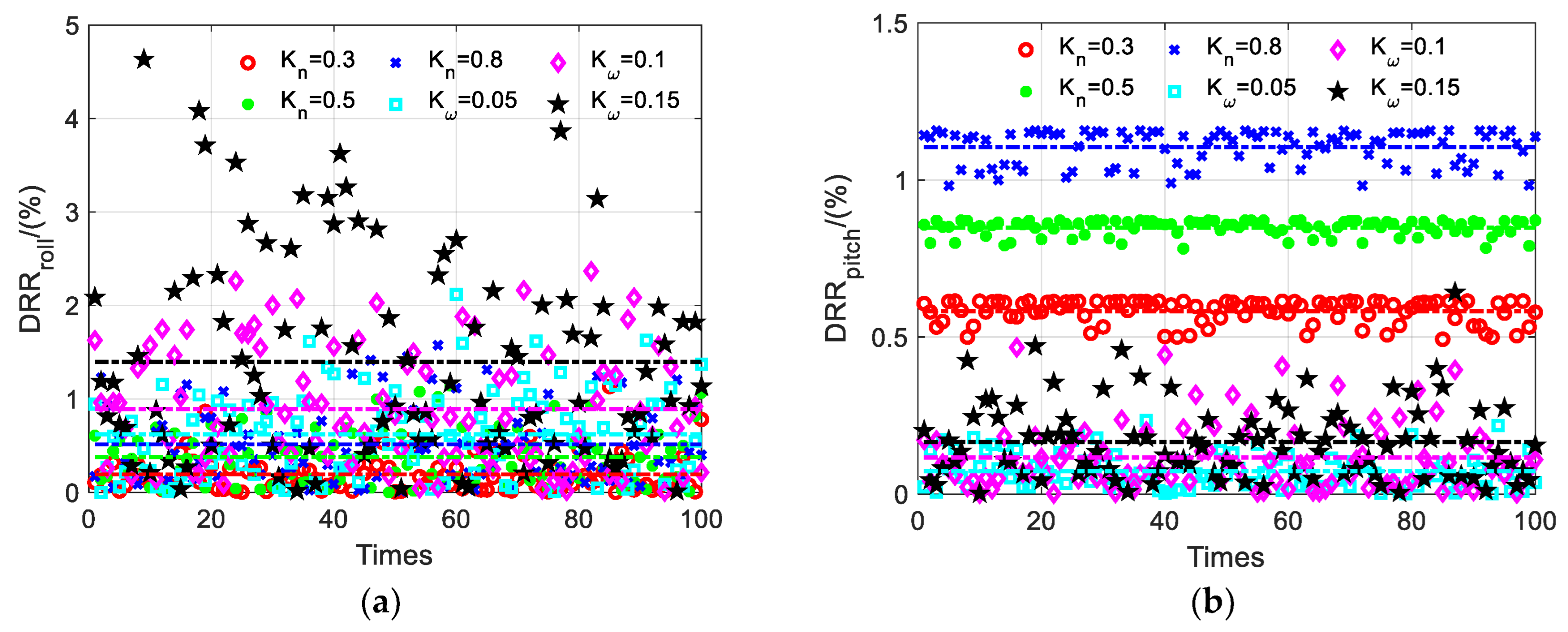
As can be seen from Figure 29, the average DRR in 100 Monte Carlo cycles under the influence of damping interference torque remains between 2% and 4%, and the DRR generated by spring torque interference is less than 1%, indicating that spring torque interference has a high robustness when the frame is rotating at a high frequency.
Maintaining the above simulation conditions, there are interference torques in both pitch and roll frame. The simulation results are shown in the following Figure 30, Figure 31 and Figure 32.
As can be seen from the simulation results, when there is a yaw direction disturbance in the aircraft attitude, tracking errors exist in both the roll frame and the pitch frame under the influence of the DRR, which cannot completely eliminate the disturbance of the aircraft attitude. The roll direction is greatly affected by K n = 0.8 under low-frequency motion, while the pitch direction is greatly affected by K ω = 0.15 under high-frequency motion. The coupling problem of aircraft disturbance information exists in both the pitch and yaw line-of-sight rate of the optical axis, and the error angle of the detector increases with the increase in the interference torque.

4.2. Tracking Ability of the Roll–Pitch Seeker

The roll–pitch seeker needs the cooperative control of the roll frame and the pitch frame to track the target. Assuming that the seeker’s optical axis points to the target at the initial time and the target moves according to a certain law, the motion characteristics of the seeker’s optical axis under different conditions were analyzed.

4.2.1. Target Single-Plane Motion

  • The direction of the target movement is the same as the direction of the disturbance of the aircraft attitude.
When the line of sight moves only in the pitch direction, the roll–pitch seeker can track the target solely through the pitch frame motion, just like the pitch–yaw seeker, without the roll frame motion. At this time, only the pitch frame has spring torque and damping torque, and the motion law of the line-of-sight angle rate is as follows:
q ˙ p = 1 / s q ˙ y = 0
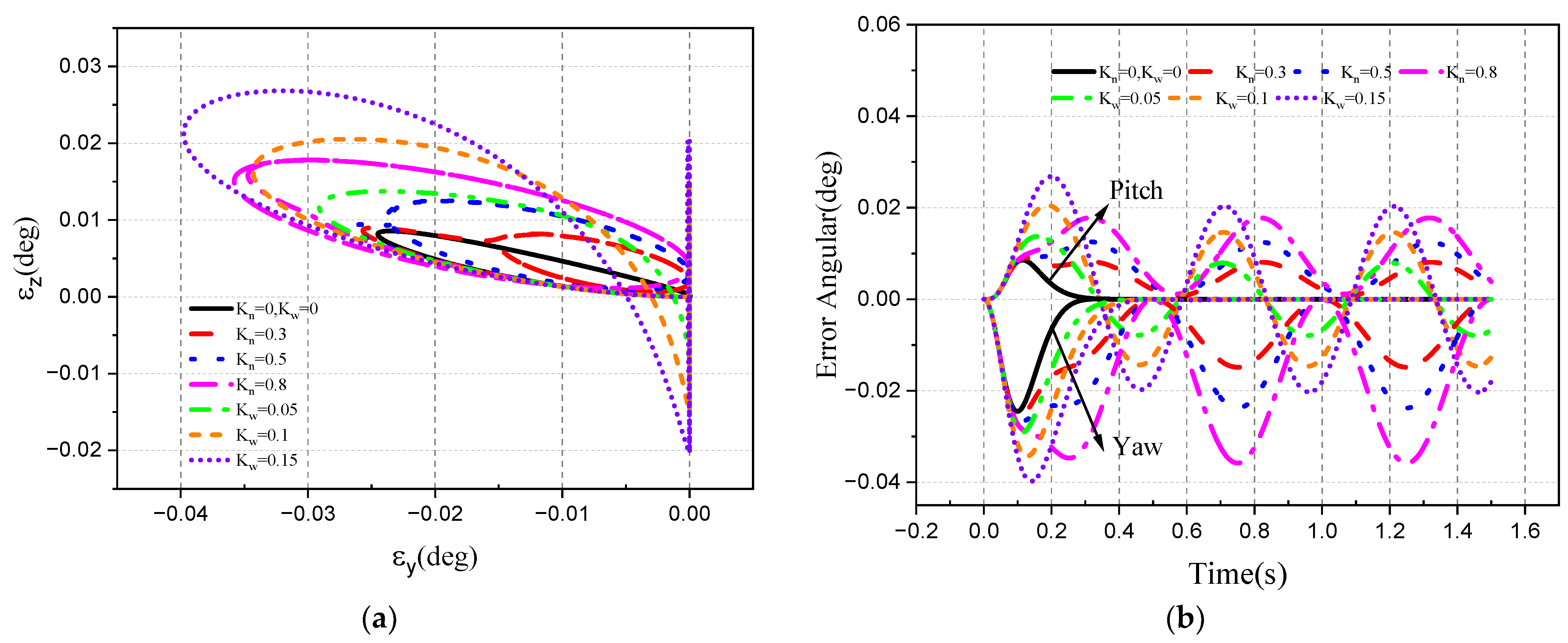
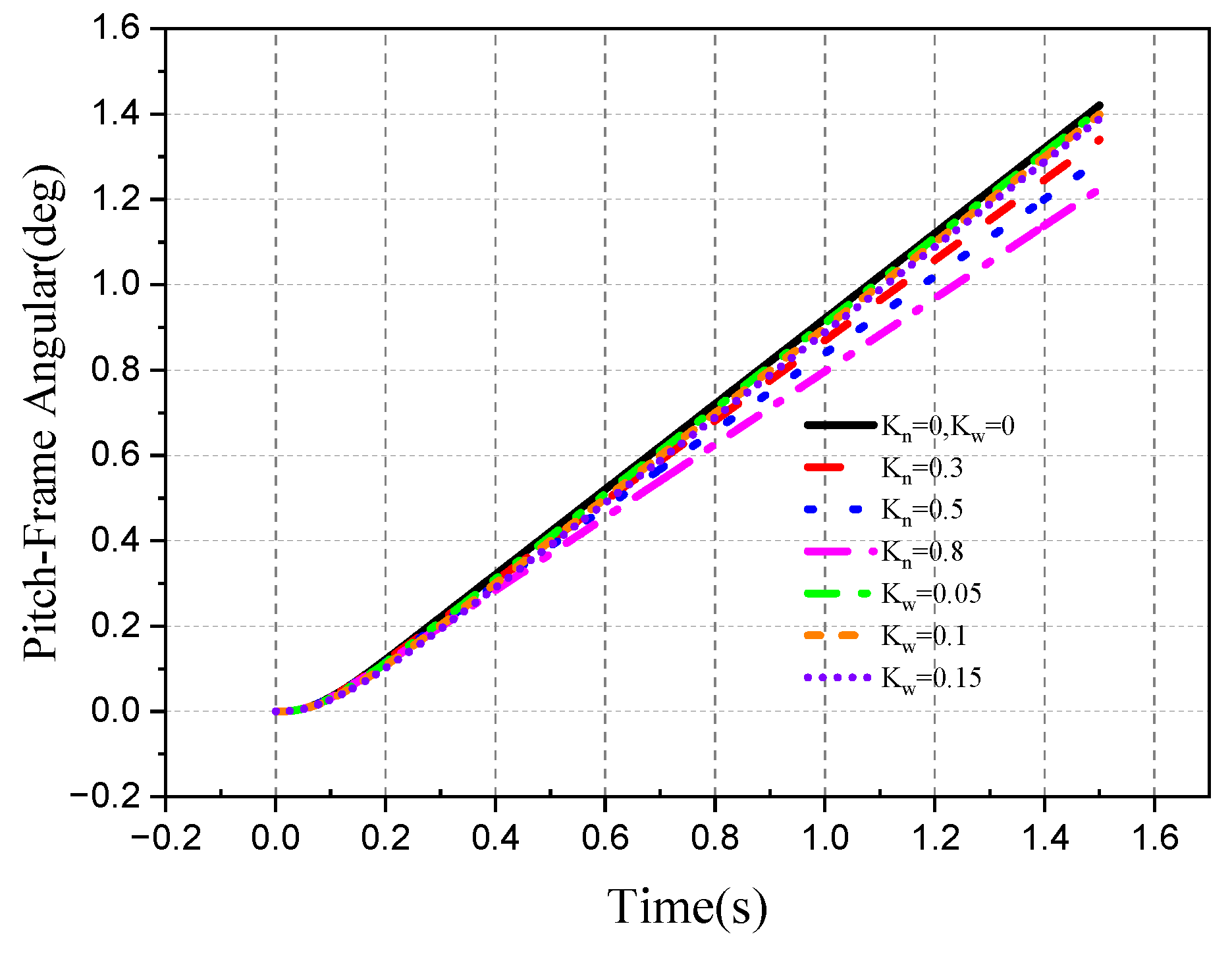
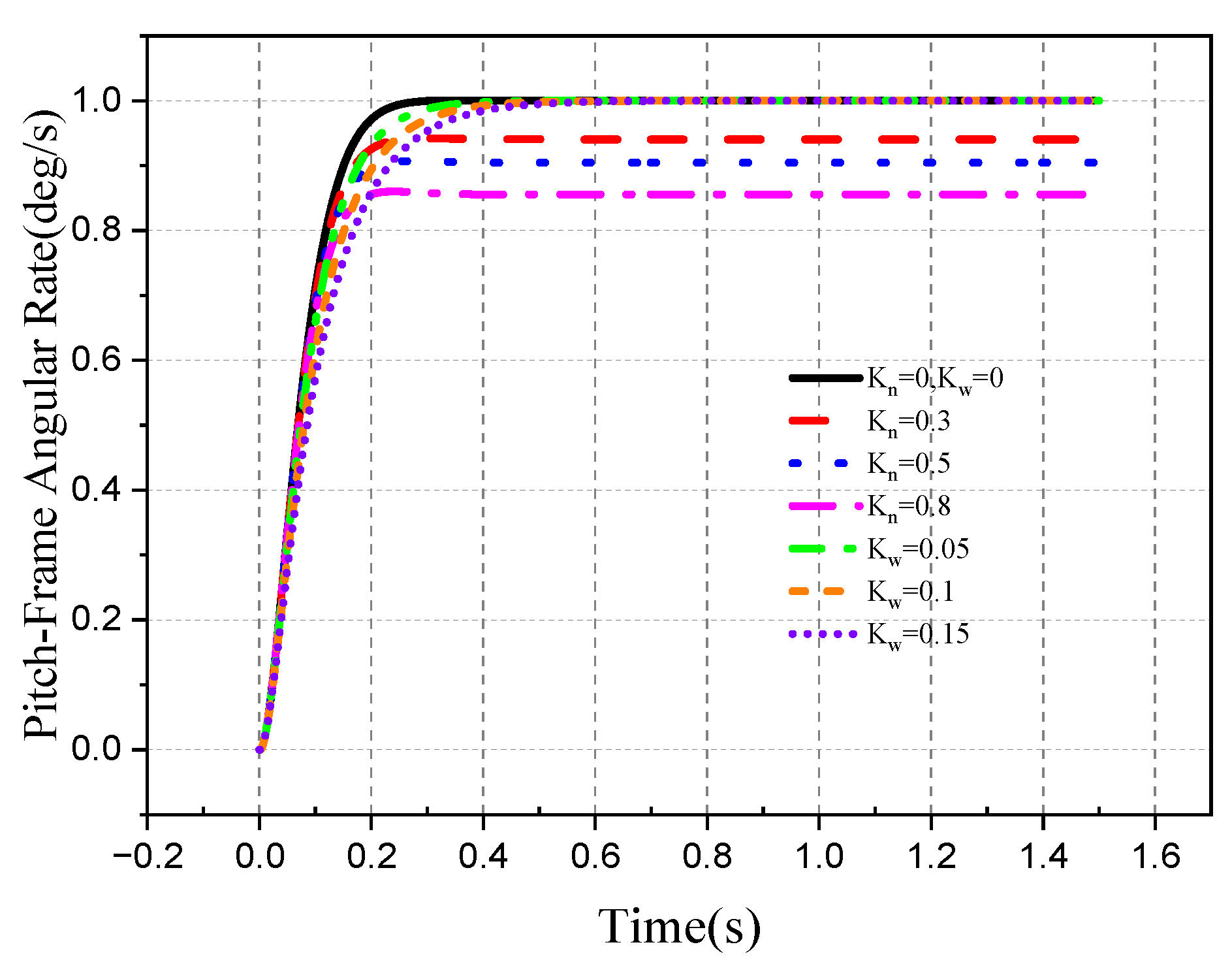
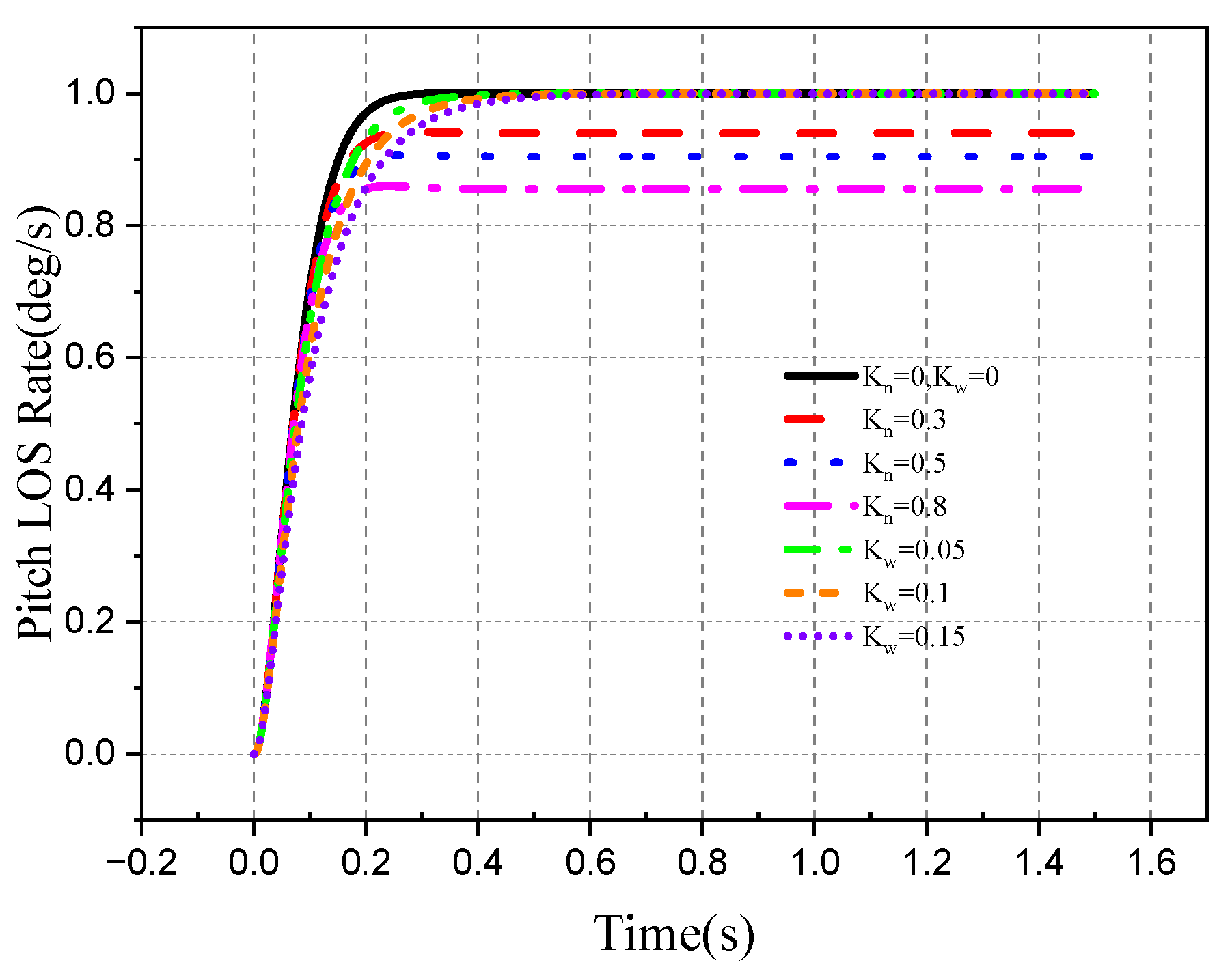
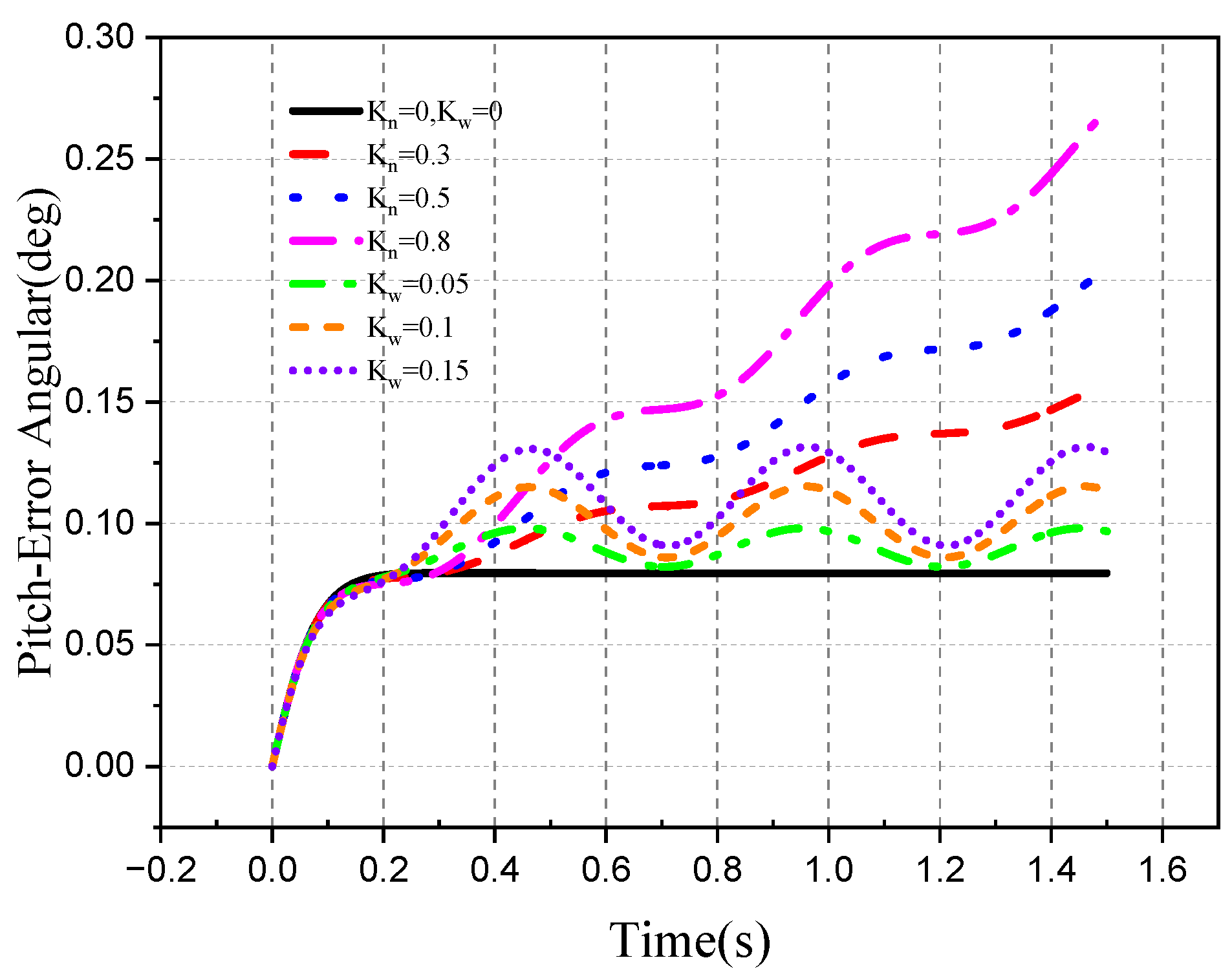
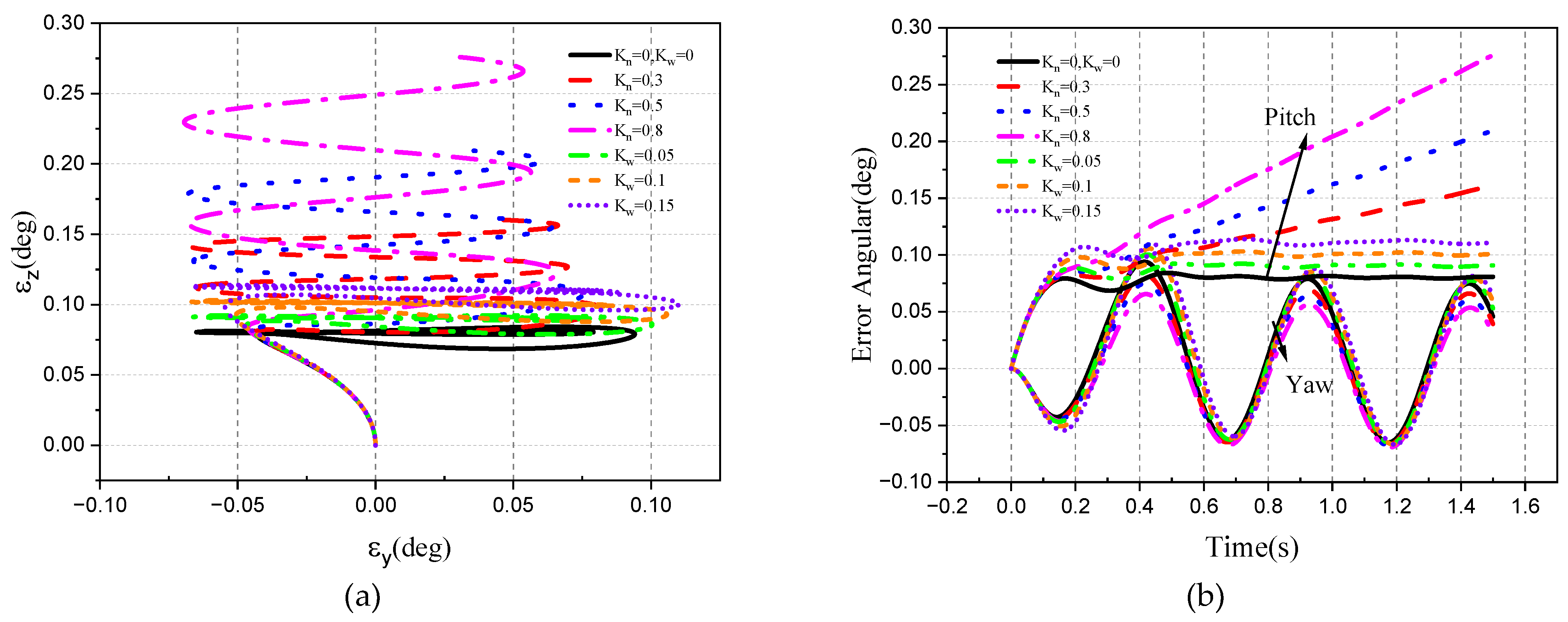
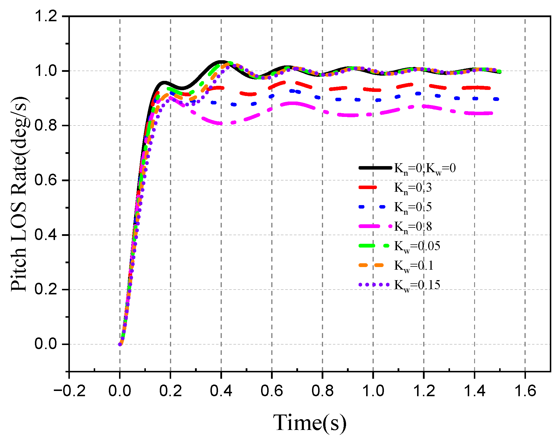
It can be seen from the simulation results that the angular velocity of the optical axis is equal to the output angular velocity of the motor. In the case of no attitude disturbance, when K n = 0.8 , the speed response of the pitch angle of the optical axis is the fastest, but the error angle of the pitch frame tracking steady state and the detector pitch direction are the largest. The damping torque has a certain influence on the tracking speed, and the damping torque is proportional to the tracking lag. The larger the damping torque coefficient, the slower the response speed of the pitch frame and the larger the steady-state error angle of the detector (Figure 33, Figure 34, Figure 35 and Figure 36).
The velocity of the above target is maintained in the pitch direction, whereas the sinusoidal disturbance exists in the pitch direction attitude, and the motion law of the attitude is as follows:
ω b y = sin 4 π t / s
At this time, the disturbance torque is added to the stable loop of the pitch frame, and the simulation results are shown in the Figure 37, Figure 38, Figure 39 and Figure 40.
As can be seen from the simulation results, when the maneuvering direction of the target is the same as the direction of the disturbance of attitude, the optical axis cannot completely isolate the disturbance of attitude. Therefore, the pitch angle velocity is affected by the DRR, coupled with the attitude disturbance information. The DRR generated by the damping torque has a greater impact on the tracking performance. It can also be verified by Figure 41 that the DRR generated by damping torque is 5%~10% on average, which is much larger than the spring torque. Therefore, when there is a high-frequency disturbance, the damping interference torque has a great influence on the seeker’s stable tracking accuracy, which also conforms to the amplitude–frequency characteristics of the DRR transfer function.
2.
The movement direction of the target is different from the disturbance direction of attitude.
The velocity of the above target is maintained in the pitch direction, while there is a sinusoidal disturbance in the yaw direction of the aircraft attitude, and the motion law of the aircraft attitude is as follows:
ω b z = sin 4 π t / s
At this time, the disturbance torque is added to the stable loop of the roll frame and the pitch frame. The simulation results are shown in the Figure 42, Figure 43, Figure 44, Figure 45, Figure 46, Figure 47 and Figure 48.
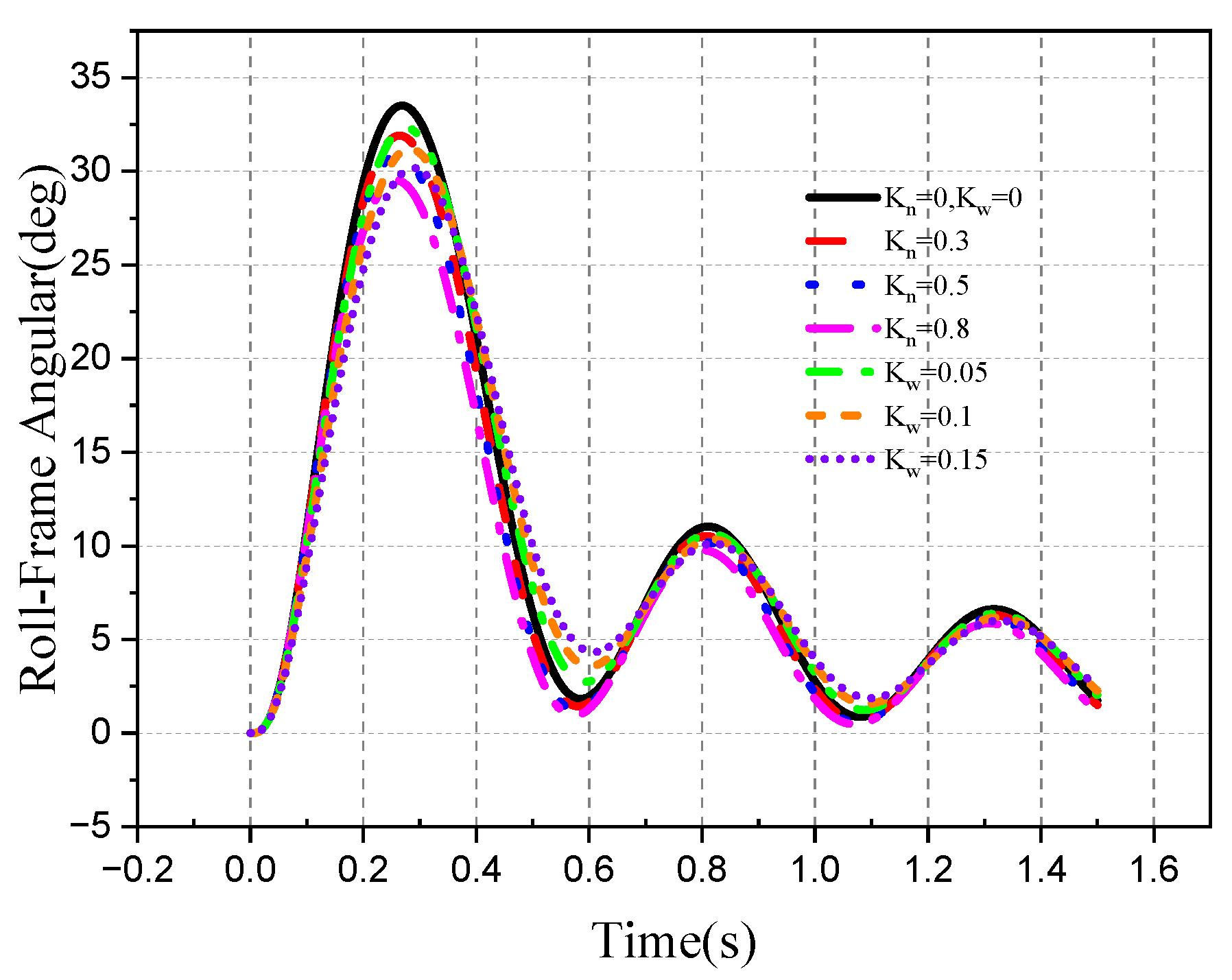
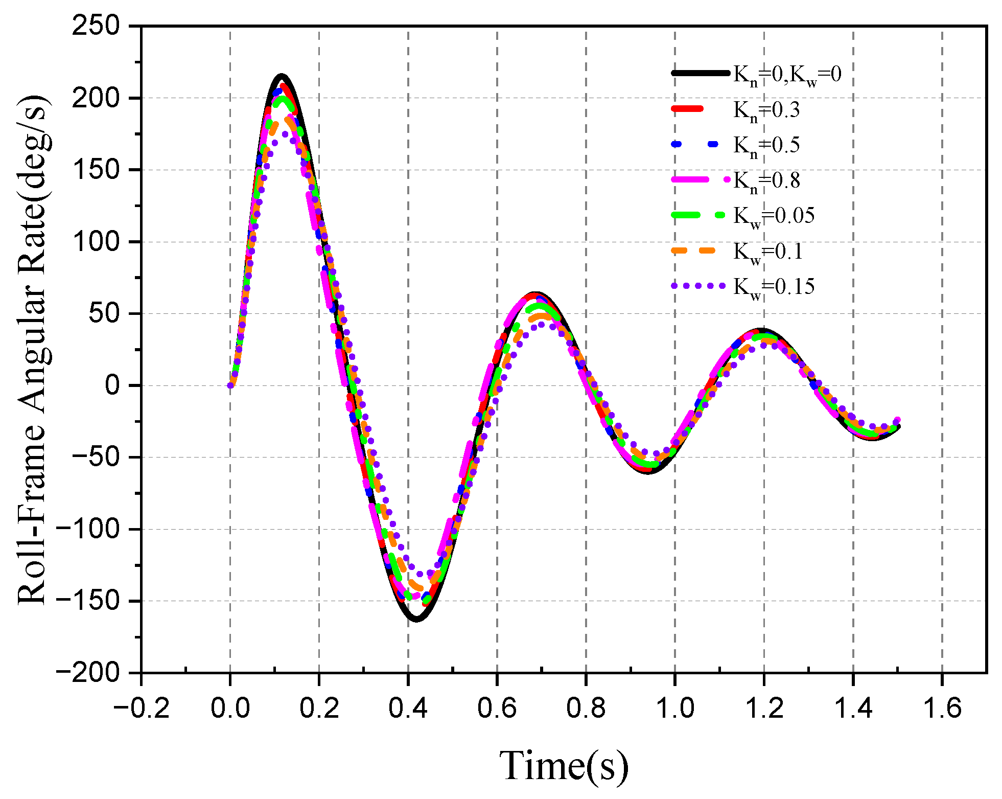
It can be seen from the simulation results that when the pitch direction needs to track the target, disturbance in the yaw direction of attitude is completely isolated, the roll frame needs to rotate according to the angular velocity of the aircraft attitude in the direction of the vector size of the tracking velocity and disturbance velocity, and there is a sinusoidal movement. According to the amplitude–frequency and phase–frequency characteristics of the DRR, it can be seen that, the damping torque has a great influence on the tracking accuracy of the angle and angular velocity of the roll frame, and there is a certain lag. Figure 49a shows that when K ω = 0.15 , the maximum DRR is approximately 4.3%. The pitch direction of the pitch frame is greatly affected by the DRR of the spring interference. It can be seen from Figure 49b that when K n = 0.8 , the maximum DRR average is approximately 6.8%, and the steady-state tracking error and detector tracking error increase with the increase in the spring torque coefficient. The pitch sight angle rate of the optical axis is significantly affected by the spring interference torque, and the yaw direction sight angle rate should be 0°/s.
Due to the special structure of the roll–pitch seeker, it is impossible to achieve complete isolation of the aircraft attitude disturbance like the pitch–yaw seeker, which allows certain detection errors. Under the high-frequency yaw direction disturbance, the seeker is greatly affected by the damping torque and the damping torque coefficient is larger. This results in a greater deviation angle of the yaw direction detector.

4.2.2. Target Space Motion

The attitude angle of the aircraft is 0. The simulation results are as follows:
  • Target tracking without aircraft attitude disturbance
The target moves in both directions in inertial space, and the line-of-sight movement is as follows:
q ˙ p = 1 / s q ˙ y = sin 4 π t / s
When there is no disturbance of attitude, the disturbance torque is added to the pitch frame and the roll frame at the same time. The simulation results are shown in the following Figure 50, Figure 51, Figure 52, Figure 53, Figure 54 and Figure 55.
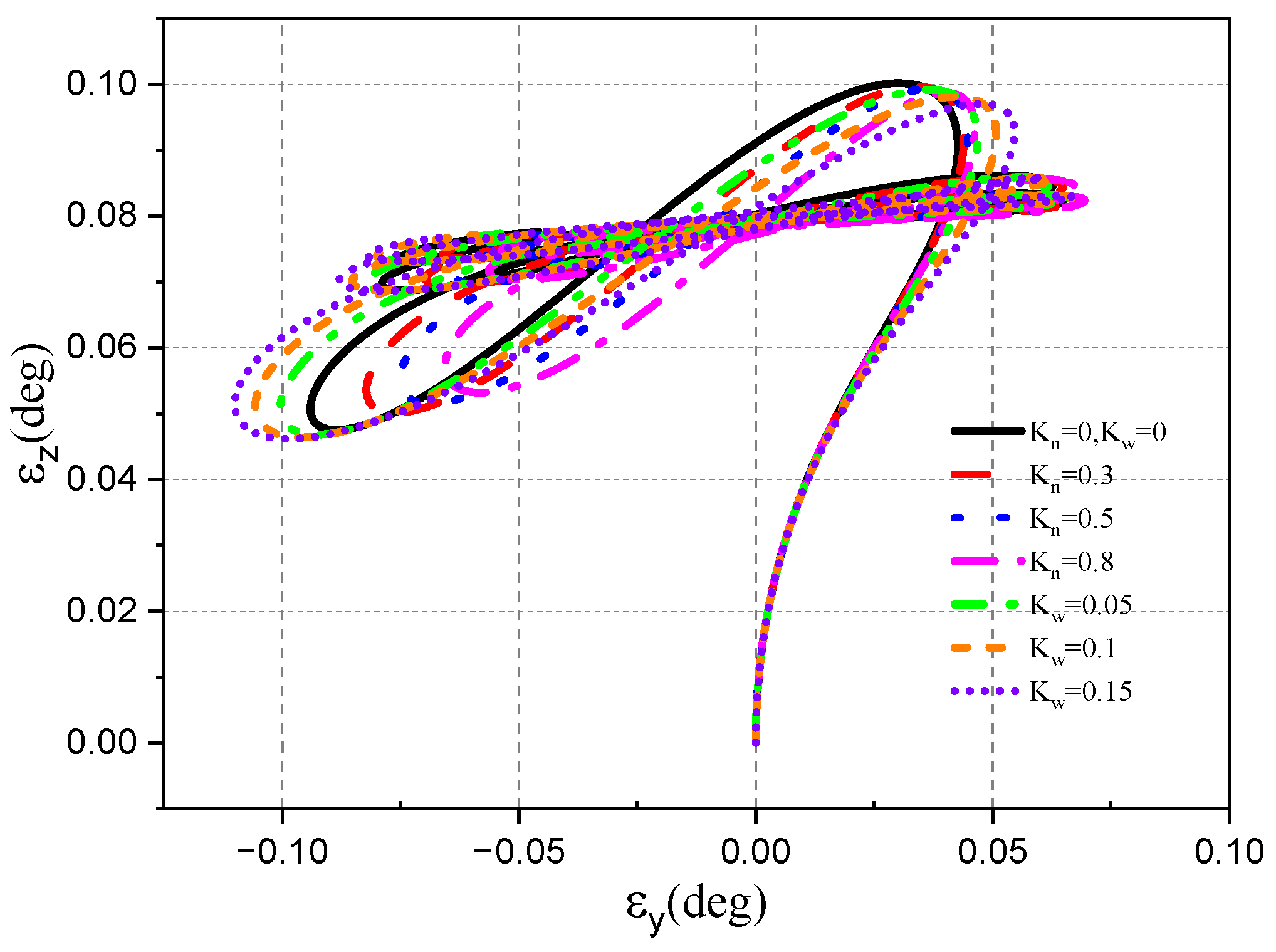
As can be seen from the figures, when the pitch direction and yaw direction track the target at the same time, the roll frame needs to rotate according to the tracking velocity in both directions and the direction of vector size, thus generating a sinusoidal motion law. According to the amplitude–frequency and phase–frequency characteristics of the DRR, when K ω = 0.15 , it has the greatest influence on the tracking accuracy of the roll frame angle and angular velocity. The pitch frame is greatly affected by the DRR of the spring interference; the steady-state tracking error will increase with the increase in the spring torque coefficient, and the tracking error of the detector pitch direction will also increase. The LOS rate of the optical axis is affected by the spring interference torque, and the DRR of the damping torque has a great influence on the LOS rate in the yaw direction. From Figure 56, Figure 57 and Figure 58, it can be seen that the torque DRR of the roll frame spring has a greater influence on the detector pitch direction error, while the damping torque DRR of the pitch frame has a greater influence on the maximum tracking error of the detector yaw direction.
2.
Target tracking under aircraft attitude disturbance
Keep the target moving in the pitch and yaw directions, while attitude disturbance is in the pitch direction, and the line-of-sight movement is as follows:
q ˙ p = 1 / s q ˙ y = sin 4 π t / s
The motion law of the aircraft attitude is:
ω b z = sin 4 π t / s
The simulation results are shown in the following Figure 59, Figure 60, Figure 61, Figure 62 and Figure 63.
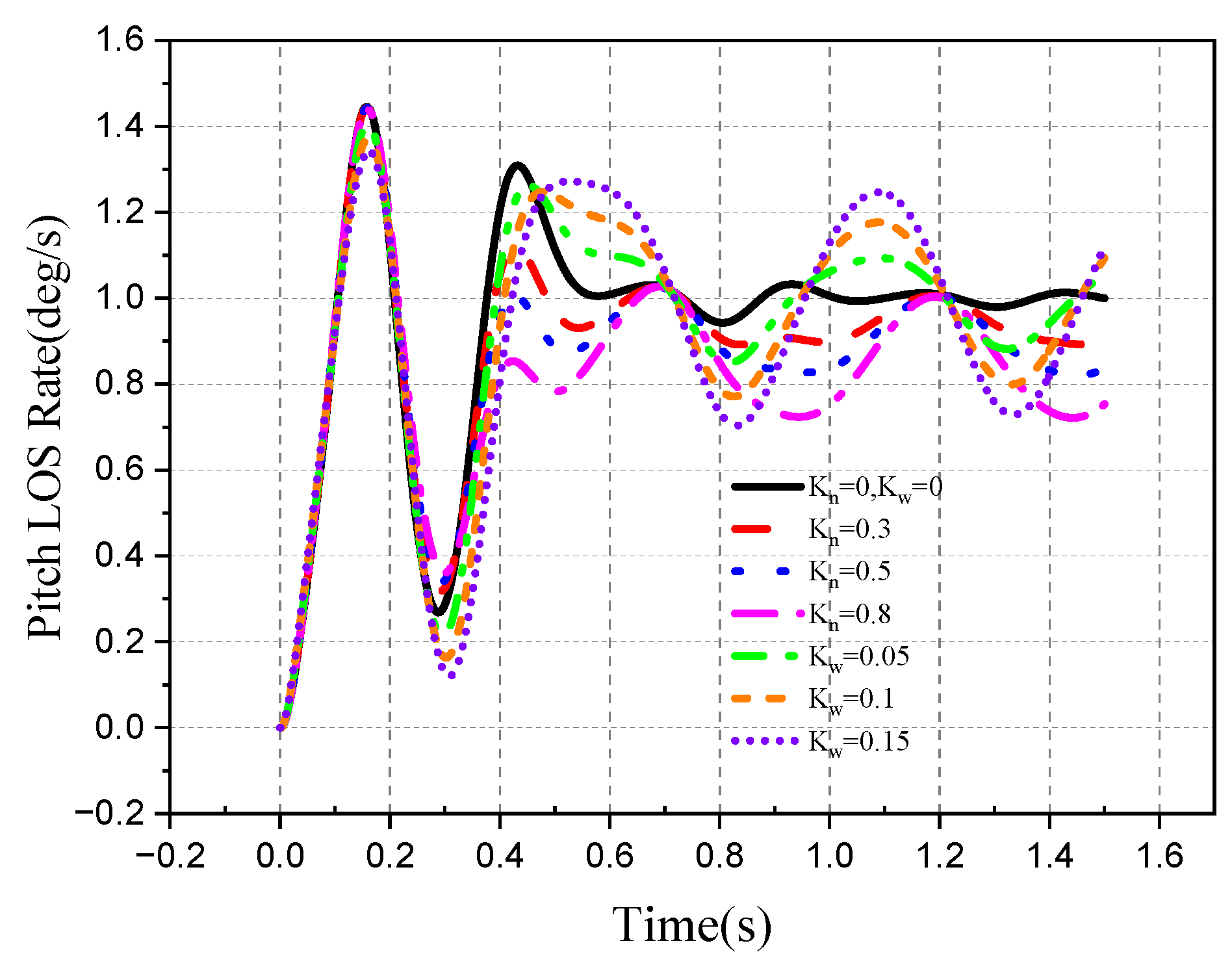
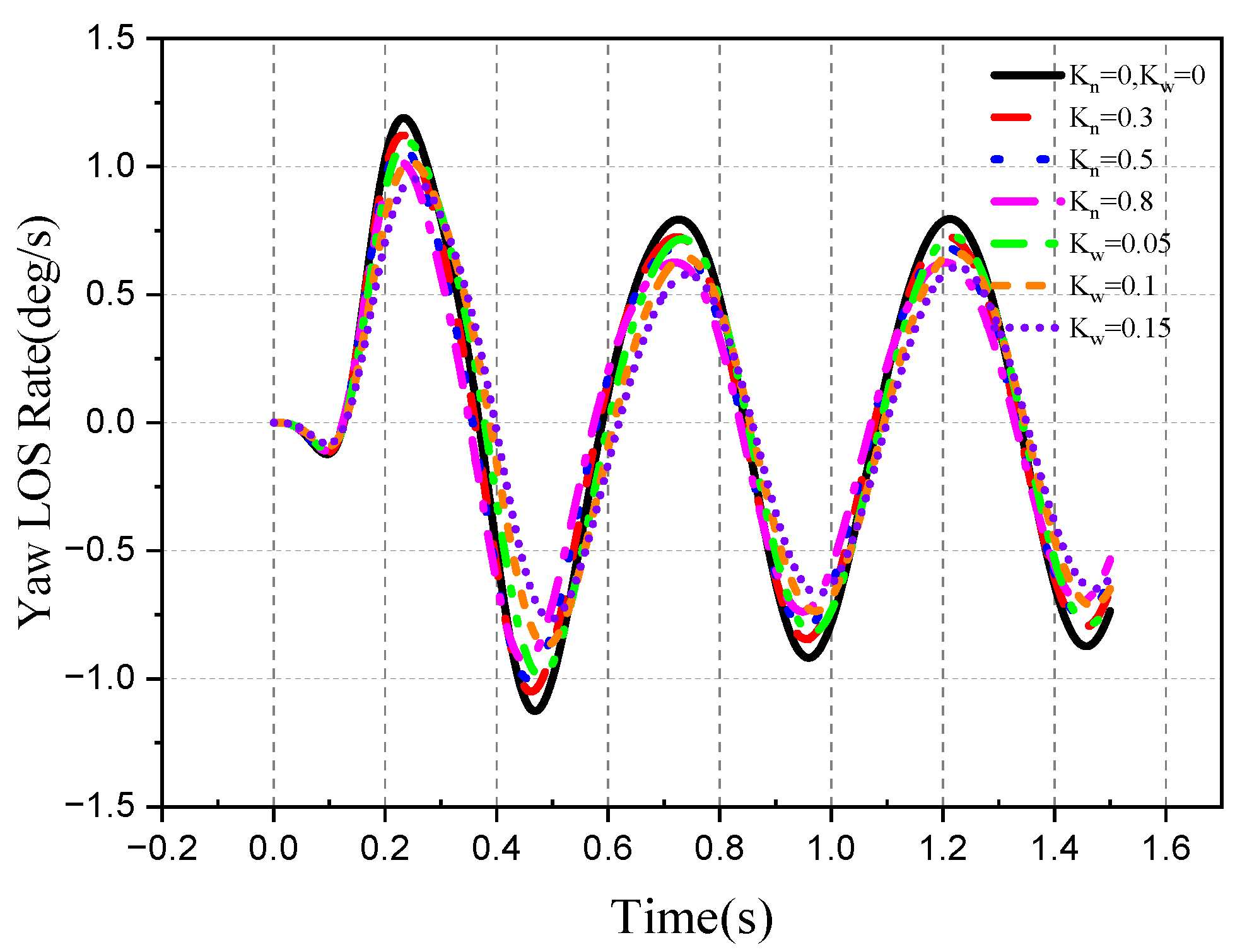
As can be seen from the simulation results, under the influence of the DRR of damping torque of the pitch frame, the pitch line-of-sight rate of the optical axis is coupled with a large amount of aircraft attitude information. This results in an increase in the pitch line-of-sight rate deviation and the detector yaw direction error in the presence of high-frequency disturbance in the pitch direction. As can be seen from Figure 64b, the average DRR generated by the pitch frame is approximately 1.1% when the spring torque K n = 0.8 .
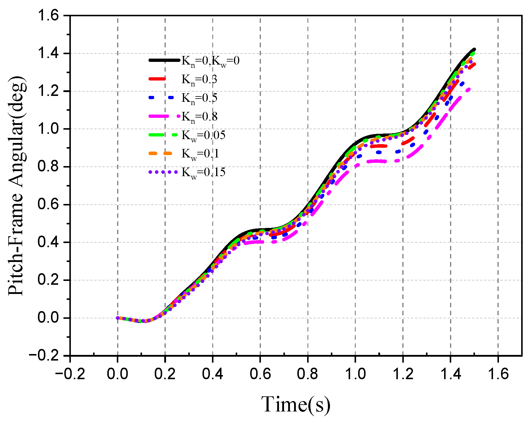
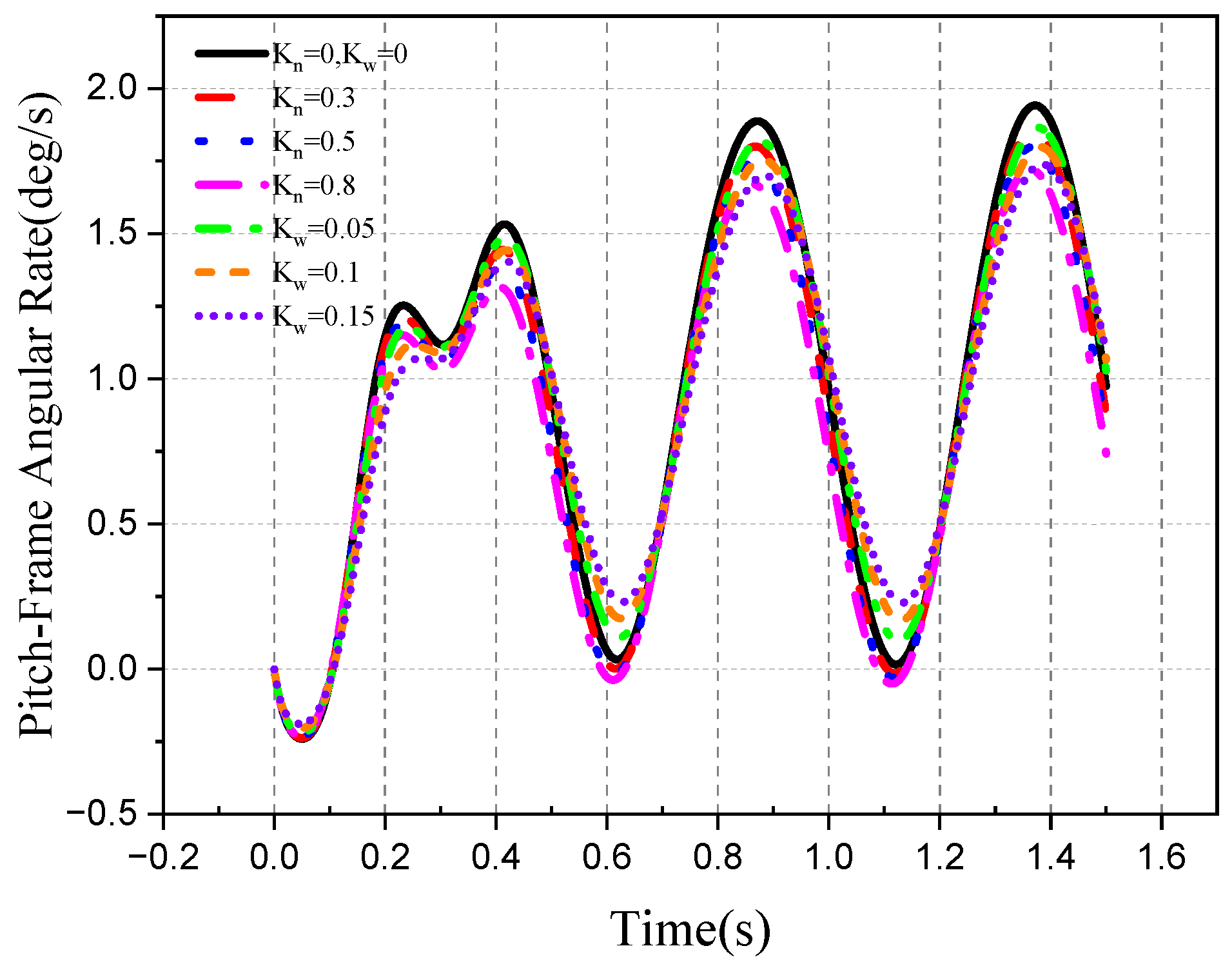
The simulation results show that when the aircraft attitude is disturbed and cannot be isolated completely, the motion of the optical axis will be disturbed by the aircraft attitude motion, and there will be a large deviation from the angular velocity of the line of sight. In the case of high-frequency attitude disturbance, the DRR of the damping torque has a great influence on target tracking accuracy, while in the case of low-frequency attitude disturbance, the spring torque has a great influence on the frame angle and LOS rate of the optical axis.

5. Conclusions

In this study, the stable tracking principle of the roll–pitch seeker was evaluated, and the influence of the DRR on the stable tracking characteristics of the roll–pitch seeker was investigated. The following conclusions can be drawn:
The roll–pitch seeker adopts a semi-strap-down mode to achieve platform stability, which can isolate the disturbance in the roll direction and pitch direction of the aircraft attitude. Furthermore, the isolation of the yaw direction disturbance requires the roll frame angle to be a tan ω b y / ω b z . The smaller the error Δ ϕ R between the roll frame angle ϕ R and the expected decoupling frame angle a tan ω b y / ω b z , the smaller the impact of the aircraft attitude disturbance. The closed-loop control of the roll seeker is to form control instructions through the error angle of the detector, drive the frame motion, reduce the error angle, make the optical axis point to the target, and realize the tracking of the target. When the frame angle instruction is a low-frequency signal, the spring torque DRR has great influence on the frame angle, frame angle rate, optical axis LOS rate and detector error angle. On the contrary, the damping torque DRR has a great influence on the stable tracking effect of the roll–pitch seeker, and there is a certain lag in the tracking process, which reduces the tracking accuracy of the seeker to the target.
Therefore, reducing the torque coefficient of the seeker itself or carrying out targeted feedforward compensation according to the control command frequency, reducing the stable tracking error of the seeker by the DRR, and improving the guidance accuracy of the aircraft are recommended. The theoretical research undertaken in this study will provide theoretical guidance for the development of aircraft.

Author Contributions

Conceptualization, B.X.; Methodology, Q.X.; Software, B.X.; Validation, T.L.; Formal analysis, B.X.; Investigation, Z.M.; Resources, Q.X.; Data curation, T.L.; Writing—Original Draft Preparation, B.X. and Q.X.; Writing—Review and Editing, T.L. and Z.M.; Visualization, B.X.; Supervision, Q.X.; Project administration, Q.X.; Funding acquisition, Q.X. All authors have read and agreed to the published version of the manuscript.

Funding

This research received no external funding.

Data Availability Statement

Not applicable.

Conflicts of Interest

The authors declare no conflict of interest.

References

  1. Zhu, D.; Zheng, Y.; Xu, W.; Bai, S. An Accurate Line-of-Sight Rate Estimation Method Based on LSTM Recurrent Neural Network for Strapdown Imaging Seeker. IEEE Sens. J. 2022, 22, 21827–21836. [Google Scholar] [CrossRef]
  2. Dehghani, M.A.; Menhaj, M.B. Integral sliding mode formation control of fixed-wing unmanned aircraft using seeker as a relative measurement system. Aerosp. Sci. Technol. 2016, 58, 318–327. [Google Scholar] [CrossRef]
  3. Zhan, S.T.; Yan, W.X.; Fu, Z. Robust control of a yaw-pitch gimballed seeker. Aircr. Eng. Aerosp. Technol. 2015, 87, 83–91. [Google Scholar] [CrossRef]
  4. Ahi, B.; Haeri, M. A high-performance guidance filter scheme with exact dynamic modeling of a pitch-yaw gimballed seeker mechanism. Mech. Syst. Signal Proc. 2020, 144, 106857. [Google Scholar] [CrossRef]
  5. Li, S.; Zhong, M.; Qin, J. The Internal Model Control Design of Three-Axis Inertially Stabilized Platform for Airborne Remote Sensing. In Proceedings of the 2012 8th IEEE International Symposium on Instrumentation and Control Technology (ISICT), London, UK, 11–13 July 2012. [Google Scholar]
  6. Jiang, H.H.; Jia, H.G.; Wei, Q. Analysis of zenith pass problem and tracking strategy design for roll–pitch seeker. Aerosp. Sci. Technol. 2012, 23, 345–351. [Google Scholar] [CrossRef]
  7. Li, D.S.; Zhang, H.Q.; Zhao, Y. Research on Modeling and Simulation for Pitch/Roll Two-Axis strapdown Stabilization Platform. In Proceedings of the IEEE 2011 10th International Conference on Electronic Measurement & Instruments, Chengdu, China, 16–19 August 2011. [Google Scholar]
  8. Arrieta, O.; Campos, D.; Rico-Azagra, J.; Gil-Martínez, M.; Rojas, J.D.; Vilanova, R. Model-Based Optimization Approach for PID Control of Pitch–Roll UAV Orientation. Mathematics 2023, 11, 3390. [Google Scholar] [CrossRef]
  9. Wang, X.C.; Mo, B.; Li, X.; Liu, F.X. A line-of-sight rate estimation method for roll-pitch gimballed infrared seeker. Optik 2019, 192, 162935. [Google Scholar] [CrossRef]
  10. Chen, J.; Zhang, Z.C.; Yi, K.; Han, Y.; Ren, Z. Snake-Hot-Eye-Assisted Multi-Process-Fusion Target Tracking Based on a Roll-Pitch Semi-strapdown Infrared Imaging Seeker. J. Bionic Eng. 2022, 19, 1124–1139. [Google Scholar] [CrossRef]
  11. Wang, Y.D.; Wang, J.; He, S.M.; Shin, H.S.; Tsourdos, A. Optimal Guidance With Active Observability Enhancement for Scale Factor Error Estimation of Strapdown Seeker. IEEE Trans. Aerosp. Electron. Syst. 2021, 57, 4347–4362. [Google Scholar] [CrossRef]
  12. Yang, H.; Bai, X.B.; Zhang, S.F. Layout Design of Strap down Array Seeker and Extraction Method of Guidance Information. Aerospace 2022, 9, 373. [Google Scholar] [CrossRef]
  13. Leomanni, M.; Bianchini, G.; Garulli, A.; Quartullo, R. Sum-of-norms periodic model predictive control for space rendezvous. IEEE Trans. Control Syst. Technol. 2021, 30, 1311–1318. [Google Scholar] [CrossRef]
  14. Eren, U.; Prach, A.; Koçer, B.B.; Raković, S.V.; Kayacan, E.; Açıkmeşe, B. Model predictive control in aerospace systems: Current state and opportunities. J. Guid. Control Dyn. 2017, 40, 1541–1566. [Google Scholar] [CrossRef]
  15. Singh, K.; Gupta, P.K.; Chaurasia, D.; Kandanvli, V.K.R. Stability of Discrete-Time Delayed Systems Subject to External Interference and Generalized Overflow Nonlinearities. IEEE Trans. Ind. Appl. 2022, 58, 5353–5364. [Google Scholar] [CrossRef]
  16. Liu, S.X.; Du, X.; Xia, Q.L. An on-line compensation method for the disturbance rejection rate of seekers. Optik 2018, 157, 1306–1318. [Google Scholar] [CrossRef]
  17. Jianmei, S.; Gaohua, C.; Xianxiang, C.; Lixia, K. Stability region analysis of the parasitic loop of the semi-strapdown homing seeker. Proc. Inst. Mech. Eng. Part I J. Syst. Control Eng. 2012, 226, 550–562. [Google Scholar] [CrossRef]
  18. Wen, Q.Q.; Lu, T.Y.; Xia, Q.L.; Sun, Z.D. Beam-pointing error compensation method of phased array radar seeker with phantom-bit technology. Chin. J. Aeronaut. 2017, 30, 1217–1230. [Google Scholar] [CrossRef]
  19. Liu, H.; Zhu, M.C.; Liu, B.; Jia, H.G. LOS stabilization and gyro configuration analysis for roll-pitch seeker. Appl. Mech. Mater. 2013, 397, 530–535. [Google Scholar] [CrossRef]
  20. Li, Y.; Wen, X.H.; Li, W.; Wei, L.; Xia, Q.L. Influence of roll-pitch seeker DRR and parasitic loop on Lyapunov stability of guidance system. J. Syst. Eng. Electron. 2021, 32, 1509–1526. [Google Scholar]
  21. Du, X.; Lv, R.; Tu, H.F.; Jiang, C.W. The research on infrared seeker with disturbance rejection effect parasitic. Optik 2018, 170, 409–419. [Google Scholar] [CrossRef]
  22. Wu, D.W.; Chen, M.; Gong, H.J. Adaptive neural flight control for an aircraft with time-varying distributed delays. Neurcomputing 2018, 307, 130–145. [Google Scholar] [CrossRef]
  23. Naghdi, M.; Sadrnia, M.A. A novel fuzzy extended state observer. ISA Trans. 2020, 102, 1–11. [Google Scholar] [CrossRef] [PubMed]
  24. Ran, M.P.; Li, J.C.; Xie, L.H. A new extended state observer for uncertain nonlinear systems. Automatica 2021, 131, 109772. [Google Scholar] [CrossRef]
  25. Huang, Y.; Wang, J.Z.; Shi, D.W.; Shi, L. Toward Event-Triggered Extended State Observer. IEEE Trans. Autom. Control 2018, 63, 1842–1849. [Google Scholar] [CrossRef]
  26. Yu, B.Q.; Shen, A.W.; Chen, B.; Luo, X.; Tang, Q.P.; Xu, J.B.; Zhu, M.F. A Compensation Strategy of Flux Linkage Observer in SPMSM Sensorless Drives Based on Linear Extended State Observer. IEEE Trans. Energy Convers. 2022, 37, 824–831. [Google Scholar] [CrossRef]
  27. Liu, X.; Mo, B.; Liu, F.X. Line-of-sight stabilization of roll-pitch seeker using differentiator-based disturbance compensation control. Proc. Inst. Mech. Eng. Part G J. Aerosp. Eng. 2020, 234, 1326–1339. [Google Scholar] [CrossRef]
  28. Lin, S.Y.; Lin, D.F.; Wang, W. A Novel Online Estimation and Compensation Method for Strap down Phased Array Seeker Disturbance Rejection Effect Using Extended State Kalman Filter. IEEE Access 2019, 7, 172330–172340. [Google Scholar] [CrossRef]
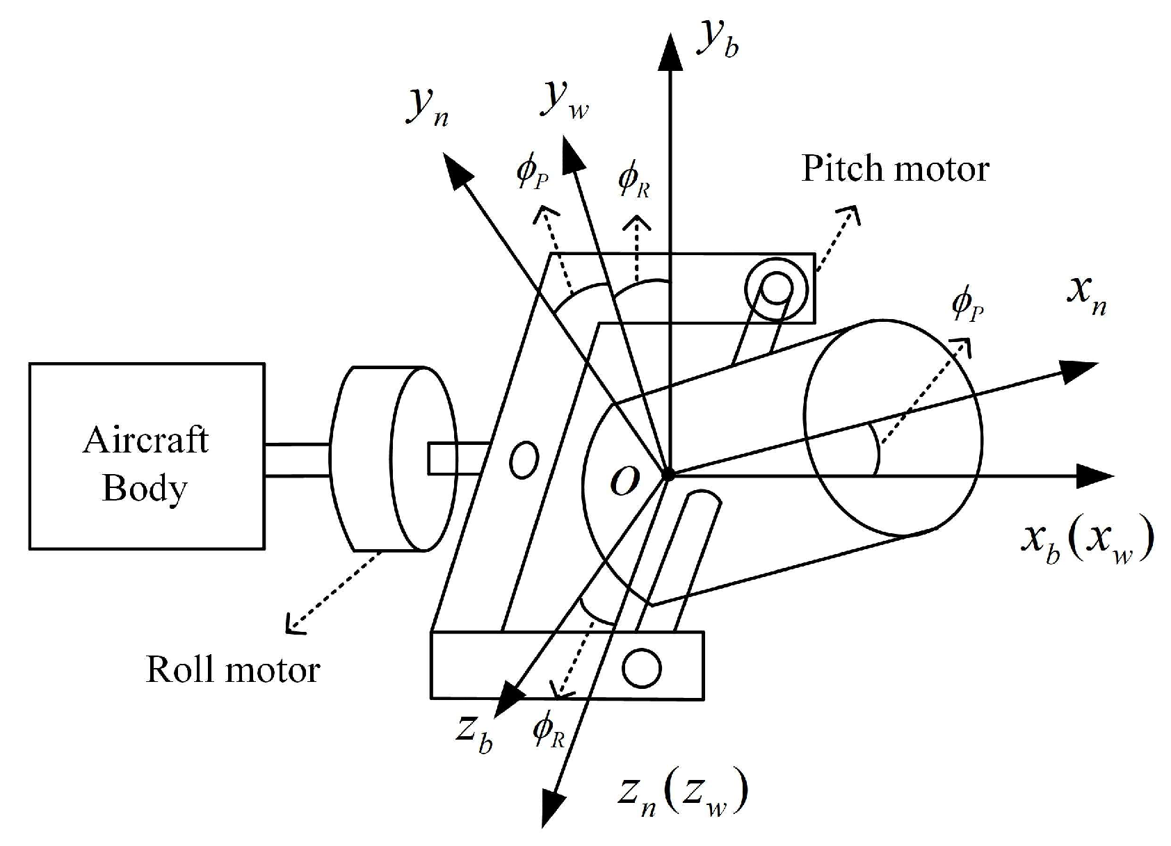
Figure 1. Scheme of the roll–pitch seeker.
Aerospace 10 00940 g001
Figure 2. Diagram of the seeker detector error angle.
Aerospace 10 00940 g002
Figure 3. Coordinate transformation relationship.
Aerospace 10 00940 g003
Figure 4. Stable loop of the roll frame.
Aerospace 10 00940 g004
Figure 5. Stable loop of the pitch frame.
Aerospace 10 00940 g005
Figure 6. Projection of the disturbance on the pitch frame coordinate.
Aerospace 10 00940 g006
Figure 7. Principle of the existence of the angular velocity of optical axis disturbance.
Aerospace 10 00940 g007
Figure 8. Schematic diagram of detector measurement error angle.
Aerospace 10 00940 g008
Figure 9. Schematic diagram of image changes on the detector: (a) Roll frame motion; (b) Pitch frame motion.
Aerospace 10 00940 g009
Figure 10. Principle of roll–pitch seeker stable control system.
Aerospace 10 00940 g010
Figure 11. Schematic diagram of coordinate transformation of roll–pitch seeker.
Aerospace 10 00940 g011
Figure 12. Frame control model.
Aerospace 10 00940 g012
Figure 13. DRR generated by roll interference torque: (a) damping torque; (b) spring torque.
Aerospace 10 00940 g013
Figure 14. Bode diagram of DRR function under different interference forces: (a) damping torque; (b) spring torque.
Aerospace 10 00940 g014
Figure 15. Roll frame angle.
Aerospace 10 00940 g015
Figure 16. Pitch frame angle.
Aerospace 10 00940 g016
Figure 17. Angular rate of roll frame.
Aerospace 10 00940 g017
Figure 18. Angular rate of pitch frame.
Aerospace 10 00940 g018
Figure 19. Optical axis pitch LOS rate.
Aerospace 10 00940 g019
Figure 20. Optical axis yaw LOS rate.
Aerospace 10 00940 g020
Figure 21. Error angle: (a) Detector error angle; (b) Pitch and yaw error angle of the Detector.
Aerospace 10 00940 g021
Figure 22. Roll frame angle.
Aerospace 10 00940 g022
Figure 23. Pitch frame angle.
Aerospace 10 00940 g023
Figure 24. Angular rate of roll frame.
Aerospace 10 00940 g024
Figure 25. Angular rate of pitch frame.
Aerospace 10 00940 g025
Figure 26. Optical axis pitch LOS rate.
Aerospace 10 00940 g026
Figure 27. Optical axis yaw LOS rate.
Aerospace 10 00940 g027
Figure 28. Detector error angle.
Aerospace 10 00940 g028
Figure 29. Pitch frame Monte Carlo simulation.
Aerospace 10 00940 g029
Figure 30. Optical axis pitch LOS rate.
Aerospace 10 00940 g030
Figure 31. Optical axis yaw LOS rate.
Aerospace 10 00940 g031
Figure 32. Error angle: (a) Detector error angle; (b) Pitch and yaw error angle of the Detector.
Aerospace 10 00940 g032
Figure 33. Pitch frame angle.
Aerospace 10 00940 g033
Figure 34. Angular rate of pitch frame.
Aerospace 10 00940 g034
Figure 35. Optical axis pitch LOS rate.
Aerospace 10 00940 g035
Figure 36. Detector error angle.
Aerospace 10 00940 g036
Figure 37. Pitch frame angle.
Aerospace 10 00940 g037
Figure 38. Angular rate of pitch frame.
Aerospace 10 00940 g038
Figure 39. Optical axis pitch LOS rate.
Aerospace 10 00940 g039
Figure 40. Detector error angle.
Aerospace 10 00940 g040
Figure 41. Pitch frame Monte Carlo simulation.
Aerospace 10 00940 g041
Figure 42. Roll frame angle.
Aerospace 10 00940 g042
Figure 43. Pitch frame angle.
Aerospace 10 00940 g043
Figure 44. Angular rate of roll frame.
Aerospace 10 00940 g044
Figure 45. Angular rate of pitch frame.
Aerospace 10 00940 g045
Figure 46. Optical axis pitch LOS rate.
Aerospace 10 00940 g046
Figure 47. Optical axis yaw LOS rate.
Aerospace 10 00940 g047
Figure 48. Error angle: (a) Detector error angle; (b) Pitch and yaw error angle of the Detector.
Aerospace 10 00940 g048
Figure 49. Monte Carlo simulation: (a) roll frame; (b) pitch frame.
Aerospace 10 00940 g049
Figure 50. Roll frame angle.
Aerospace 10 00940 g050
Figure 51. Pitch frame angle.
Aerospace 10 00940 g051
Figure 52. Angular rate of roll frame.
Aerospace 10 00940 g052
Figure 53. Angular rate of pitch frame.
Aerospace 10 00940 g053
Figure 54. Optical axis pitch LOS rate.
Aerospace 10 00940 g054
Figure 55. Optical axis yaw LOS rate.
Aerospace 10 00940 g055
Figure 56. Error angle: (a) Detector error angle; (b) Pitch and yaw error angle of the Detector.
Aerospace 10 00940 g056
Figure 57. Detector error angle in case the DRR exists in the pitch frame.
Aerospace 10 00940 g057
Figure 58. Detector error angle in case the DRR exists in the roll frame.
Aerospace 10 00940 g058
Figure 59. Pitch frame angle.
Aerospace 10 00940 g059
Figure 60. Angular rate of pitch frame.
Aerospace 10 00940 g060
Figure 61. Optical axis pitch LOS rate.
Aerospace 10 00940 g061
Figure 62. Optical axis yaw LOS rate.
Aerospace 10 00940 g062
Figure 63. Error angle: (a) Detector error angle; (b) Pitch and yaw error angle of the Detector.
Aerospace 10 00940 g063
Figure 64. Monte Carlo simulation: (a) roll frame; (b) pitch frame.
Aerospace 10 00940 g064
Table 1. Roll frame and pitch frame control loop parameter.
ParameterRoll Frame Pitch FrameUnit
Tracking loop gain G12412-
Stable loop gain G21818-
Resistance R13.512.5Ω
Inductance L0.006750.0075H
Rotational inertia J0.00870.00305Kg m2
Torque coefficient KT0.810.28Nm/A
Disclaimer/Publisher’s Note: The statements, opinions and data contained in all publications are solely those of the individual author(s) and contributor(s) and not of MDPI and/or the editor(s). MDPI and/or the editor(s) disclaim responsibility for any injury to people or property resulting from any ideas, methods, instructions or products referred to in the content.