Article

Mild Detonation Initiation in Rotating Detonation Engines: An Experimental Study of the Deflagration-to-Detonation Transition in a Semiconfined Flat Slit Combustor with Separate Supplies of Fuel and Oxidizer

by
Igor O. Shamshin
1,
Vladislav S. Ivanov
1,
Viktor S. Aksenov
1,2,
Pavel A. Gusev
1,
Konstantin A. Avdeev
1 and
Sergey M. Frolov
1,2,*
1
Department of Combustion and Explosion, Semenov Federal Research Center for Chemical Physics of the Russian Academy of Sciences, 119991 Moscow, Russia
2
Institute of Laser and Plasma Technologies, National Research Nuclear University MEPhI, 115409 Moscow, Russia
*
Author to whom correspondence should be addressed.
Aerospace 2023, 10(12), 988; https://doi.org/10.3390/aerospace10120988
Submission received: 2 November 2023 / Revised: 21 November 2023 / Accepted: 22 November 2023 / Published: 23 November 2023
(This article belongs to the Special Issue Advances in Detonative Propulsion)

Abstract

:
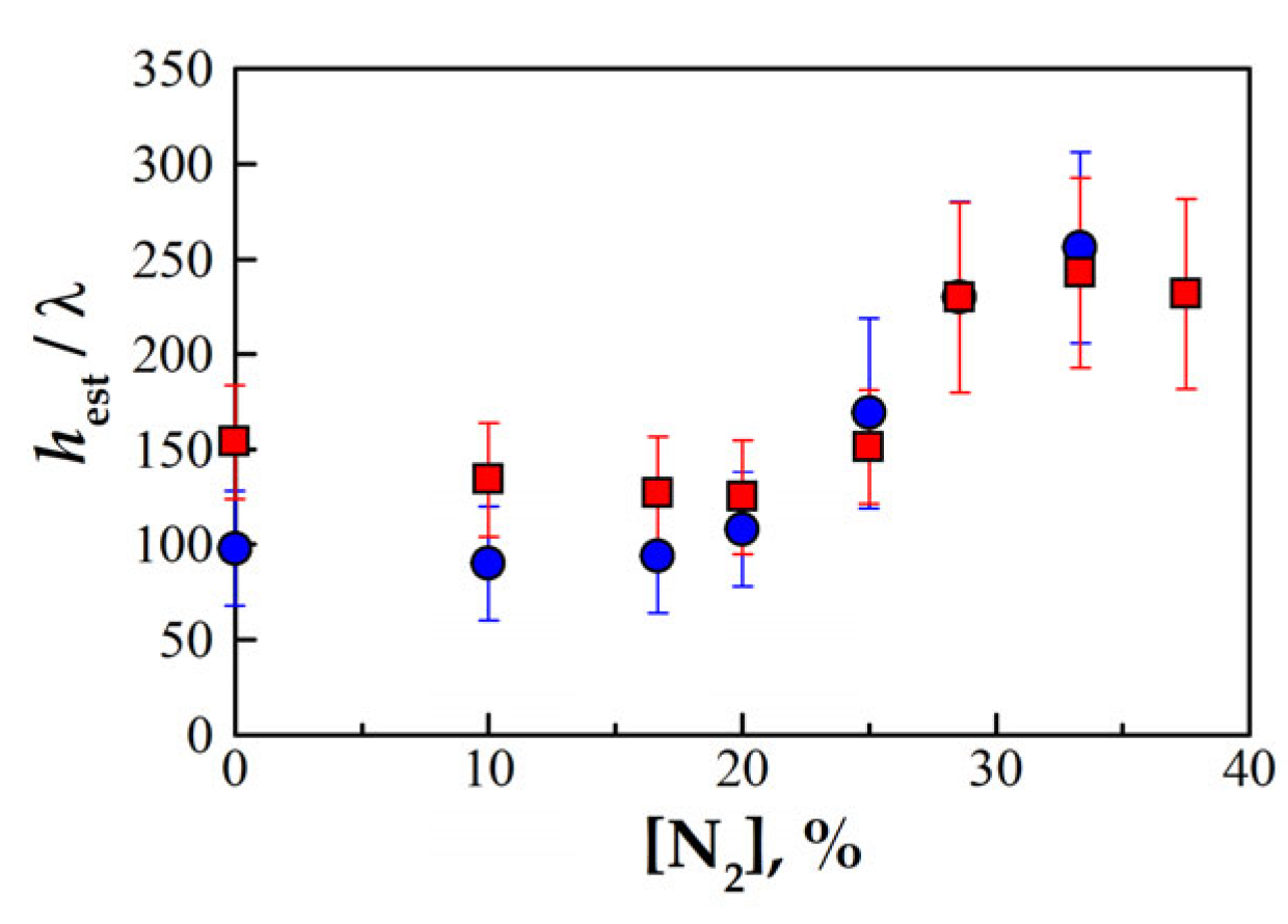
Rotating detonation engines (RDEs) are considered to be promising thrusters for aerospace propulsion. Detonation initiation in RDEs can be accompanied by a destructive explosion of an excess volume of the fuel mixture in the combustor. To exclude this phenomenon, a “mild” rather than “strong” initiation of detonation is required. For the mild initiation of detonation in RDEs, it is necessary to ignite a mixture of a certain minimum volume sufficient for deflagration-to-detonation transition (DDT). In this study, the critical conditions for detonation initiation through DDT in a semiconfined slit combustor simulating the RDE combustor with a separate supply of ethylene and oxygen diluted with nitrogen (from 0 to 40%) were obtained experimentally. It turned out that for the mild initiation of detonation, it is necessary to ignite the mixture upon reaching the critical (minimum) height of the combustible mixture layer. Thus, for the mild initiation of detonation in the undiluted C2H4 + 3O2 mixture filling such a slit combustor, the height of the mixture layer must exceed the slit width by approximately a factor of 12. In terms of the transverse size of the detonation cell λ the minimum layer height of such mixtures in experiments is ~150λ. Compared to the experiments with the premixed composition, the critical height of the layer is 20% larger, which is explained by the finite rate of mixing. As the degree of oxygen dilution with nitrogen increases, the critical height of the layer increases, and the role of finite rate mixing decreases: the results no longer depend on the method of combustible mixture formation.

1. Introduction

The combustor in rotating detonation engines (RDEs), which are considered to be promising thrusters for aerospace propulsion, is commonly an annular slit between the outer wall and the central body [1,2,3,4,5,6]. Before starting the RDE, the slit is first filled with an explosive mixture of fuel and oxidizer to a certain level, and then the mixture is ignited to initiate one or several detonation waves that continuously circulate in the combustor and produce thrust due to the continuous outflow of detonation products into the ambience through an RDE nozzle. The critical height of the layer required for steady-state detonation propagation in the annular slit combustor of an RDE must meet the empirical criterion [1]: h = (12 ± 5)λ, where λ is the detonation cell size. Detonation can be initiated by either a strong or weak ignition source [7]. Strong ignition sources create intense shock waves in the explosive mixture and can initiate detonation directly by shock-to-detonation transition (SDT). Weak ignition sources simply ignite the explosive mixture, giving birth to a propagating flame, which can accelerate and cause a deflagration-to-detonation transition (DDT). Although the characteristic time and mixture volume required for SDT are considerably less than those required for DDT, the energy requirement for SDT is significantly larger than that for DDT. Upon the existence of a certain excess volume of the explosive mixture inside and outside the RDE combustor, detonation initiation via both SDT and DDT can cause an undesired destructive explosion [8]. In view of this, there is a need for a careful control of timing of the fill and ignition processes inside the RDE combustor to ensure mild detonation initiation followed by the establishment of the on-design operation process. The objective of this work is to find the conditions for mild detonation initiation via DDT in a flat, semiconfined layer of explosive mixture.
The first study of detonation waves steadily rotating in an annular slit with the lateral expansion of detonation products was reported by Voitsekhovskii [9]. Sommers and Morrison [10] studied both theoretical and experimental detonation propagation in semiconfined flat layers of gaseous explosive mixtures with oxygen surrounded by inert gas and showed that a detonation wave was affected by the type of inert gas (air or helium) and by the height of the layer. It was also found that detonation waves failed to propagate in the layer when the layer height was less than a certain critical (minimal) value. Dabora et al. [11] proposed a theory of the layered detonation. Adams [12] conducted experiments with long layers of explosive mixtures and detected low rates of detonation decay in layers of a near-critical height. Based on two-dimensional numerical simulations of layered detonation, Ivanov et al. [13] found that detonation waves propagated in the unsteady pulsating mode when the layer height approached the critical value. Reynaud et al. [14] reported the results of numerical simulations of cellular detonations in layers of H2–air mixture bounded by inert gas. The phenomenon of layered detonation implies the existence of mixing zones with nonuniform mixture composition near the layer edges. Systematic studies of detonation propagation in layers with transversal nonuniformities in mixture compositions are reported in [15,16,17,18,19,20,21,22]. The flow structure in the two-layered medium was found to depend on the detonability of mixtures in both layers. Rudy et al. [23] and Kuznetsov et al. [24] showed that the nonuniformity of the H2 concentration in the layer of the H2–O2 mixture had a significant effect on the critical height of the layer, which was about 3λ for a uniform H2–O2 mixture.
All studies mentioned above dealt with established detonations propagating along the layers of explosive mixtures. Only a few researchers studied DDT rather than established detonations in the semiconfined layers of explosive mixtures [8,24,25,26,27]. Kuznetsov et al. [24] and Grune et al. [25] promoted DDT in layers of explosive mixtures by installing turbulizing obstacles in the combustor. Shamshin et al. studied DDT in layers of nonpremixed [8] and premixed [26] explosive mixtures in a flat-slit combustor with smooth walls using ethylene as a fuel and oxygen diluted with nitrogen as an oxidizer. Ivanov et al. [27] reported the results of three-dimensional calculations focused on revealing the conditions for DDT in the semiconfined layer of premixed ethylene–oxygen–nitrogen mixture in terms of the critical height of the layer, the maximum dilution of the mixture with nitrogen, and the maximum slit width.
In RDEs, the fill of the combustor with an explosive mixture is studied by many researchers. For example, recently Lemcherfi e al. [28] and Liu [29] experimentally studied the effect of reactant injection and mixing on detonation wave propagation in an optically accessible linear detonation combustor. Shi et al. [30] computationally studied the effect of injection pattern in terms of location and width of injection slots on the wave structure and performance of the RDE. Wang et al. [31] studied computationally the effect of ozone addition to a hydrogen–air mixture on the multiwave operation process of the RDE. Zhou et al. [32] studied experimentally the operation process in the RDE fueled by liquid kerosene and oxygen-enriched air with kerosene injection through a series of small holes inclined by 60° to the radial direction. RDEs fueled by an ethylene–oxygen–nitrogen mixture were studied in [1,33,34,35,36,37].
This work is considered as the continuation of [8], where only preliminary results for DDT in layers of nonpremixed ethylene–oxygen–nitrogen mixture were obtained. Compared to [8], the experimental facility was modified to ensure better in situ mixing of fuel and oxidizer in the slit combustor. Also, as compared to [8], the range of mixture composition was considerably extended and included fuel-lean and fuel-rich rather than only stoichiometric compositions.

2. Materials and Methods

2.1. Experimental Setup

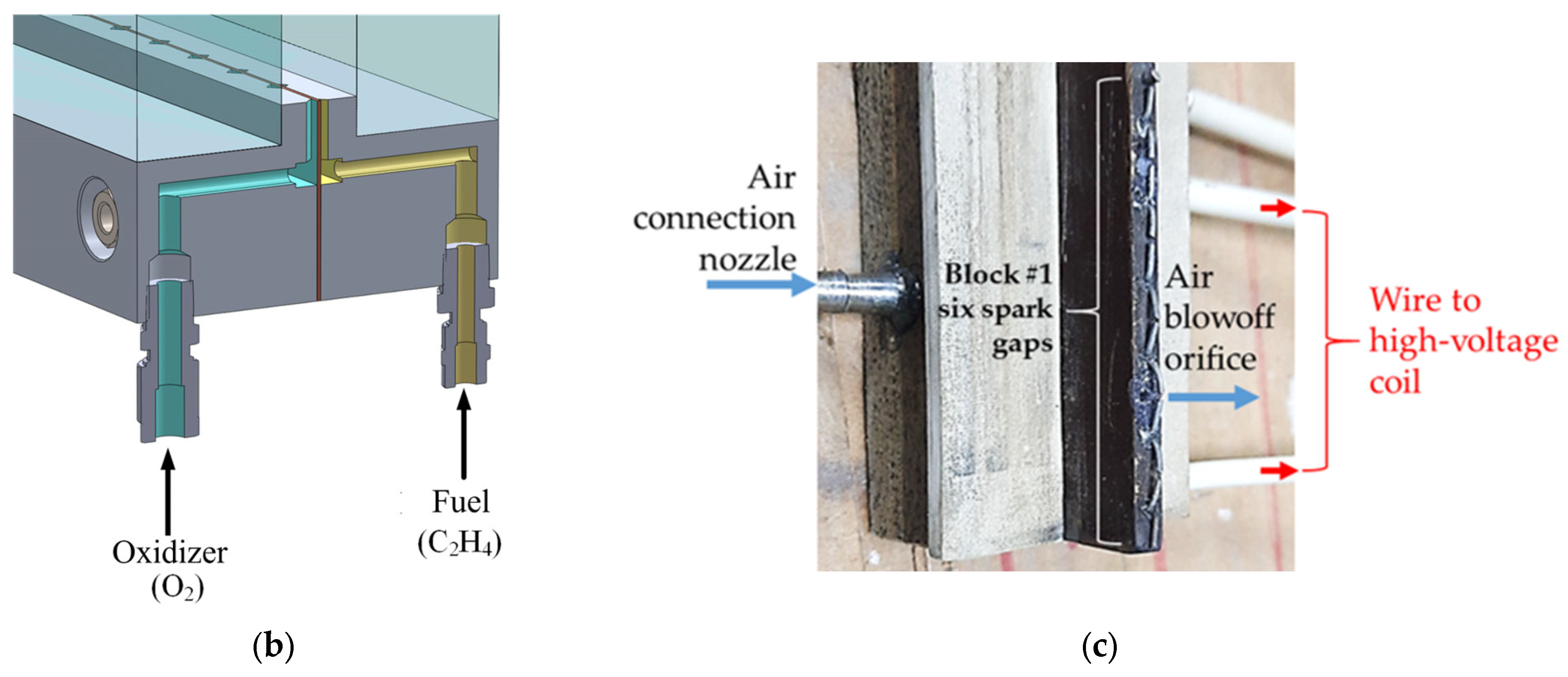
Figure 1a shows a schematic of the experimental setup. The setup consists of a slit combustor, a supply system of fuel and oxidizer, an ignition system, and a data acquisition system. The slit combustor is formed by two parallel slabs of organic glass 40 mm thick, 400 mm high, and 800 mm long. The slabs are fixed in a steel frame with two horizontal rows of windows: three 234 × 163 mm windows in the top row and three 234 × 181 mm windows in the bottom row. The slit width (6.5 ± 0.2 mm), height (394 ± 1 mm), and length (784 ± 1 mm) are fixed. Thus, the slit volume is 2.00 ± 0.04 L. Fuel (ethylene) and oxidizer (pure oxygen or a mixture of oxygen and nitrogen) are supplied to the slit from the fuel and oxidizer receivers through three parallel manifolds with solenoid valves and discharge orifice plates. The cross section and length of the manifolds is 6 × 6 mm2 and 810 mm, respectively. At the slit bottom, the manifolds are ended by two rows of calibrated injector nozzles separated by a thin foil 0.1 mm thick (Figure 1b). The diameter of the injector nozzles (1.0, 1.4, 2.0, or 2.8 mm) is selected for the appropriate flow rate and fill time. Note that the slit width of 6.5 mm was chosen as a sort of an average value among the values reported in the literature for RDEs fueled by ethylene–oxygen–nitrogen mixtures.
The volume of the fuel and oxidizer receivers is 2 and 4 L, respectively. In the experiments, a combustible mixture is formed directly in the slit when fuel and oxidizer are injected from a flat bottom through a series of evenly distributed triangular holes (the nominal cross section of fuel and oxidizer holes is 1 and 3 mm2, respectively) with a pitch of 5 mm. A mixture of oxygen and nitrogen is prepared by partial pressures in a 12 L mixer equipped with a fan and is later used to fill the oxidizer receiver. Pure oxygen is supplied to the oxidizer receiver directly from the oxygen cylinder. The fuel receiver is filled with ethylene in a similar manner. Before the experiment, the receivers are filled to a required pressure value. The volume of gas entering the slit combustor is determined by the pressure difference before and after the experiment. To measure pressure, digital pressure gauges (Fande, China) of 1.6 MPa with a reduced error of 0.1% are used. Gas consumption varies from experiment to experiment depending on the pressures in both receivers and the required fuel-to-oxidizer ratio Φ . All experiments are conducted at normal pressure and temperature (NPT) conditions.
Experiments can be divided into six groups according to the total consumption of fuel and oxidizer: (1) 0.4–0.5 L/s; (2) 1.2–1.6 L/s; (3) 2.3–2.8 L/s; (4) 4.4–5.5 L/s; (5) 7.0–8.8 L/s; and (6) 10.0–13.4 L/s. The height of the mixture layer depends on the pressure in the receivers, the selected injector nozzle, and the injection time, i.e., the time during which the solenoid valves in the fuel and oxidizer supply manifolds are open. The solenoid valves are controlled by a digital controller operating according to a given cyclogram. The left end of the slit combustor is closed by an insulator with 39 spark gaps installed in a row, divided into 7 groups (Figure 1c). Each group of spark gaps is provided with an individual high-voltage ignition coil. The primary windings of 7 ignition coils are connected in parallel, and, according to a signal from the digital controller, a storage electrolytic capacitor with a capacitance of 220 μF charged to a voltage of 318 ± 2 V is discharged through an optosimistor. During breakdown in the spark gaps, a part of the energy stored in the storage capacitor is released. According to [38], during breakdown and arc discharge, only about 10% of the energy stored in the capacitor goes to heat the gas. Taking this into account, the total energy of 39 sparks during ignition is estimated at 0.8–1.0 J or 15–20 mJ per spark gap. Taking into account that the end area on the spark gap side is 6.5 × 394 = 2561 mm2, one obtains an upper estimate for the initiation energy at a level of 390 J/m2. Considering the spark gap as a continuous linear source, which can be characterized by the energy released per unit length, one obtains for such an ignition source an estimate for the initiation energy equal to 2.6 J/m.
To purge the combustor with air, a hole with a diameter of 1.8 mm is provided in the space between the spark gaps at a height of 20 mm. After burnout of the mixture in the slit, the gap is immediately (~10 ms after ignition) purged with air through this hole in a volume of 30 to 100 L, which is many times greater than the volume of the slit (2 L). Before the experiment, the right end of the slit combustor is sealed with thin parchment paper 32 ± 2 μm thick. The upper end of the slit is open. At a distance of X P 1 = 4 mm, X P 2 = 260 mm, X P 3 = 508 mm, and X P 4 = 764 mm from the ignition source (at a height of 23 mm), 4 Kistler 211B3 pressure sensors (sensors P1, P2, P3, and P4, respectively) are installed, forming three measuring segments with a length of X 12 = 256, X 23 = 248, and X 34 = 256 mm, respectively. Signals from pressure sensors are recorded with a sampling frequency of 500 kHz by a QMS20 analog-to-digital converter (ADC) from R-Technology (Moscow, Russia). Using the indicated measuring segments, the average velocities D 12 , D 23 , and D 34 of a shock or detonation wave are determined from pressure records. The error in calculating the average shock/detonation wave velocity is estimated at 1%. The process of flame/detonation propagation is recorded by a high-speed Photron FastCam SA-Z video camera (Tokyo, Japan). After scaling, the location (coordinates X D D T and Y D D T ) and time ( t D D T ) of detonation onset as well as the propagation velocity of the luminosity front, U f , (i.e., the flame or detonation front) are determined from the video recording. The error in measuring the coordinates of the luminosity front is estimated at ±2 pixels or ±3 mm.

2.2. Experimental Procedure

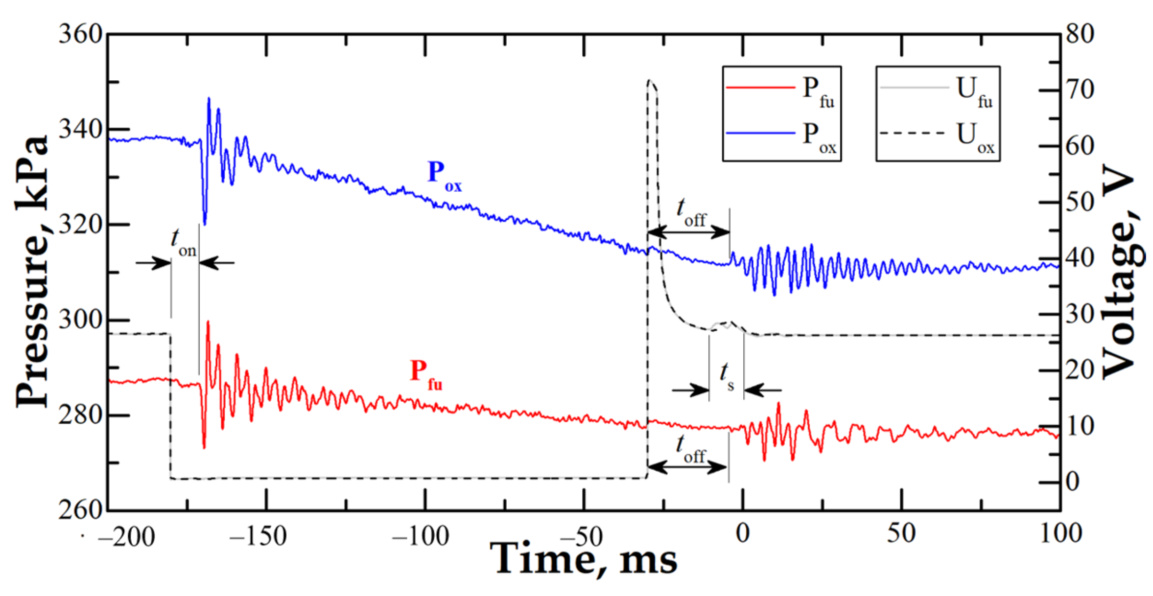
Experiments are performed according to the following procedure. Before the experiment, the digital controller is programmed to set the on and off times of the actuators (the solenoid valves and the ignition module) in accordance with the experiment cyclogram. The starting of the video camera is synchronized with the turning on of the ignition. The fuel and oxidizer receivers are filled with the corresponding gas. The following operations are then performed. First, the solenoid valves are turned on, through which fuel and oxidizer are supplied from the receivers to the slit combustor for a preset time interval, ensuring the required level of combustor fill. Second, a signal is sent for ignition. Ignition can be triggered either in advance or with a delay relative to the instant of closing the solenoid valves. Third, after a certain period of time, usually less than 10 ms, the solenoid valve for purging the slit combustor with air is turned on. This is necessary to reduce the time of thermal exposure of combustion products to the wall material (organic glass) for preserving its optical properties. The switching time of the solenoid valves from the “closed” state to the “open” state is 2–5 ms. The turn-on delay is 8–10 ms, and the turn-off delay is 25–30 ms. Due to differences in the characteristics of individual coils on valves (ohmic resistance and inductance) and mechanical differences of valves (differences in the mass of plungers and spring stiffness), the switching and reswitching time of valves in a group can vary from 0 to 10 ms. With a volumetric flow rate of 15 L/s (maximum value), about 150 mL of gas will have time to enter the slit in 10 ms or, taking into account the slit volume of 2 L, a layer with a height of ~30 mm will have time to form. When analyzing the experimental results, this feature of the gas supply system must be taken into account. The response time of the valves also depends on the pressure drop: with an increase in the pressure drop, the on and off delays, as well as the switching time, increase. The actual duration of fuel and oxidizer supply into the slit is determined by analyzing changes in records of voltage on the solenoid coils and pressure in the receivers. Figure 2 shows a typical example of such records. The estimated layer height, h e s t (mm), is determined based on the actual fill time, t i n (ms), and the volume of the mixture, V m = V f u + V o x :
t i n = min   t f u , t o x + m i n   ( 0 , t i g n )
h e s t = H t i n 101,325 V c V f u P f u 1 P f u 2 t f u + V o x P o x 1 P o x 2 t o x
where V c = 2.0 ± 0.04 L is the slit volume; V f u = 2.0 L is the volume of fuel receiver; V o x = 4.0 L is the volume of oxidizer receiver; H = 394 mm is the slit height; t f u is the actual fuel fill time; t o x is the actual oxidizer fill time; t i n is the actual time interval of joined fuel and oxidizer fill prior to ignition; P f u 1 is the pressure in the fuel receiver before the experiment; P f u 2 is the pressure in the fuel receiver after the experiment; P o x 1 is the pressure in the oxidizer receiver before the experiment; P o x 2 is the pressure in the oxidizer receiver after the experiment; and t i g n is the ignition delay time (when t i g n < 0, it is the ignition advance time).
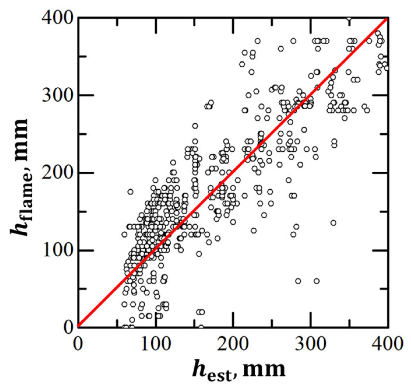
Based on video recording of the luminosity front, the height of the layer is determined at the initial stage of flame propagation ( h f l a m e ) when the luminosity front covers a distance of 10 mm hidden from observation by the metal frame and appears in the window in the visual observation area. Figure 3 shows the dependence h f l a m e vs. h e s t , illustrating the deviation of the true height of the layer from its estimated value. In experiments with premixed compositions [26], the values of h f l a m e and h e s t differed insignificantly when the height of a combustible mixture layer was less than 100 mm. However, when increasing the layer height, blurring of the layer boundary became noticeable due to the difference in flame-front velocities at the slit bottom and at the upper boundary of the layer. In the experiments with a separate supply of fuel and oxidizer considered herein, a significant scatter in the h f l a m e values is observed. This scatter is nearly symmetrical with respect to the straight line in Figure 3 corresponding to the equality h f l a m e = h e s t . The values below the straight line with h f l a m e < h e s t can be caused by poor mixing of fuel with oxidizer, mixture heterogeneity, and incomplete displacement of air during slit fill. The values above the straight line with h f l a m e > h e s t can be caused by high speeds of fuel and oxidizer jets, leading to the formation of a combustible mixture layer with a height greater than the calculated height, e.g., in cases of elevated flow rates or short injection times, when stationary gas flow rates are not established.
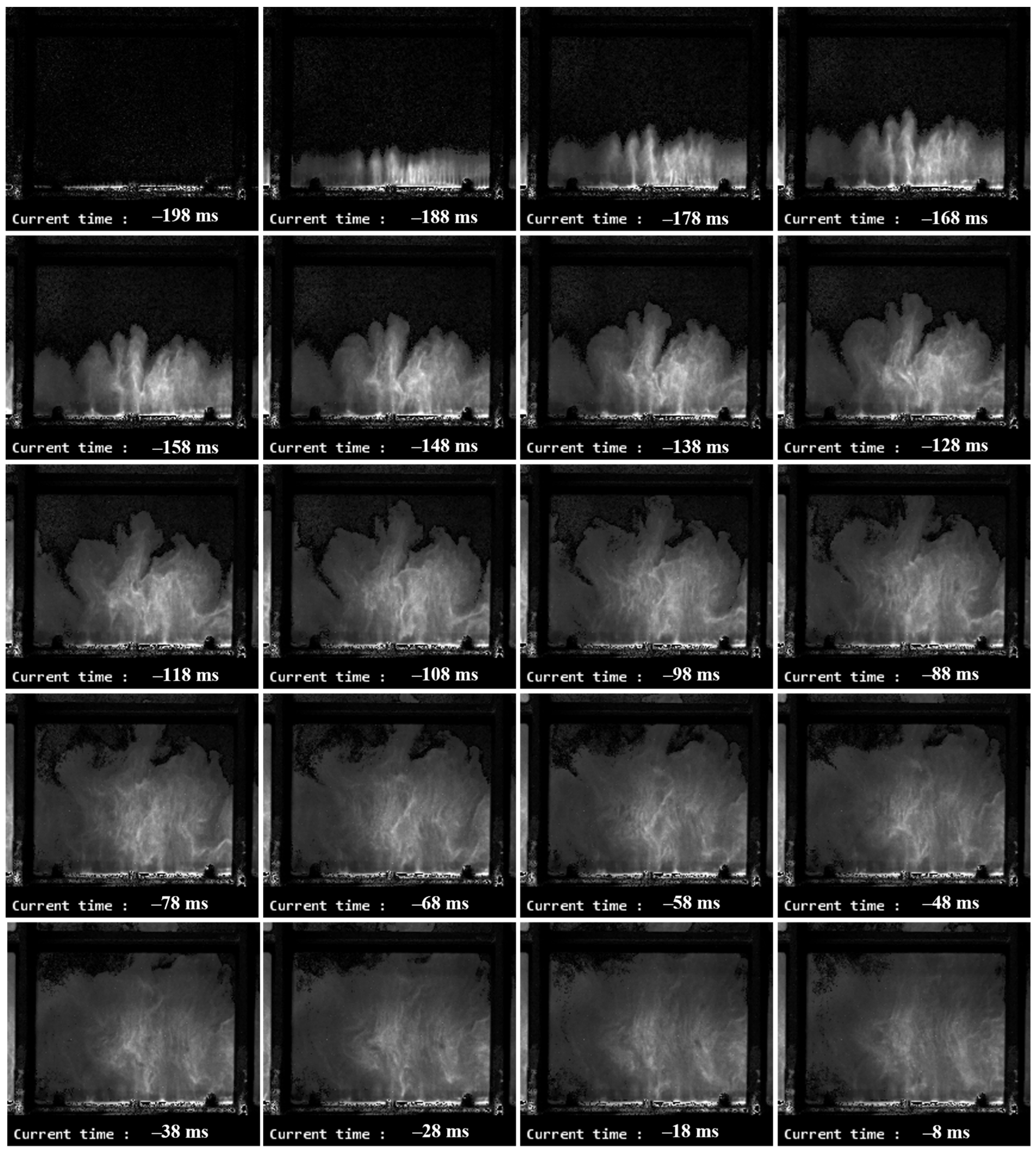
The combustible mixture forms due to mixing of coaxial gaseous jets of fuel and oxidizer injected into a flooded space filled with air under NPT conditions. The flow is turbulent, and the composition of the mixture changes in both space and time. In essence, each experiment turns out to be the implementation of a unique set of initial parameters. Figure 4 shows video frames of the slit fill process visualized using fine MgO particles. For this purpose, MgO powder was sifted through a sieve (mesh size 0.14 mm) on the open top of the slit so that the slit was seeded with MgO particles from above. As a result, after the particles settled at the bottom of the slit, a thin layer of particles was formed at the slit bottom. When the supply of fuel and oxidizer was turned on, the particles were picked up by the gas flow. In Figure 4, the particles reflect the incident light and are clearly visible in the video frames, which makes it possible to trace the motion of the gas flow. The experiment under consideration lasted 198 ms, so the estimated height of the combustible mixture layer should be equal to h e s t = 100 mm. In fact, upon ignition, the actual height of the layer was h f l a m e 170 mm. The height of the window along the inner edges of the metal frame is 177 mm. As one can see, the layer height is above and below this edge in some regions, but on average it is above 100 mm. From the images, one can estimate the speed of displacement of the outer boundary of the gas with particles. According to these estimates, the initial speed of the jets is 4–5 m/s, and the speed at the layer boundary before ignition is 0.7–1.0 m/s. The calculated speed of layer-by-layer fill of the slit with the mixture at a flow rate of 2.6 L/s is 0.5 m/s. Thus, as a statistical value, h e s t is a characteristic of the average height of the mixture layer; however, the actual height of the mixture layer undergoes significant fluctuations both during one experiment and from experiment to experiment. Note that MgO powder was applied for visualizing only the fill process and was not used in tests with ignition and combustion.
To establish a statistical pattern of DDT, it is necessary to repeat the same experiment many times with a fixed set of parameters controlled during the experiment, namely, the initial pressure in the fuel and oxidizer receivers and the injection time. In this work, the number of experiments with the same initial parameters varied from 5 to 7. In cases where doubts arose about the reliability of determining the DDT probability, additional experiments were conducted in order to clarify the critical conditions in terms of the “DDT go–DDT no go” criterion. Thus, the critical conditions for DDT in the layer were determined taking into account the probabilistic nature of DDT.

3. Results

3.1. DDT Probability

Table 1 shows the compositions of nine studied combustible mixtures C2H4 + 3(O2 + βN2), the dilution of oxygen with nitrogen [N2] = β/(1 + β), Chapman–Jouguet (CJ) detonation parameters (velocity D C J and pressure P C J ), measured detonation velocity D 34 , and peak pressure P , as well as a certain minimum height of the mixture layer, h m i n , at which DDT was recorded, both in experiments with mixtures composed directly in the slit, i.e., with separate supply of fuel and oxidizer, and in homogeneous mixtures [26]. This series of experiments was performed at such pressure values in the fuel and oxidizer receivers at which the overall consumption of fuel and oxidizer corresponded to a stoichiometric ratio. The statistical spread of the stoichiometric ratio values did not exceed the measurement error; the stoichiometric ratio value was maintained equal to 1 with an accuracy of 0.06, i.e., Φ = 1.00 ± 0.06.
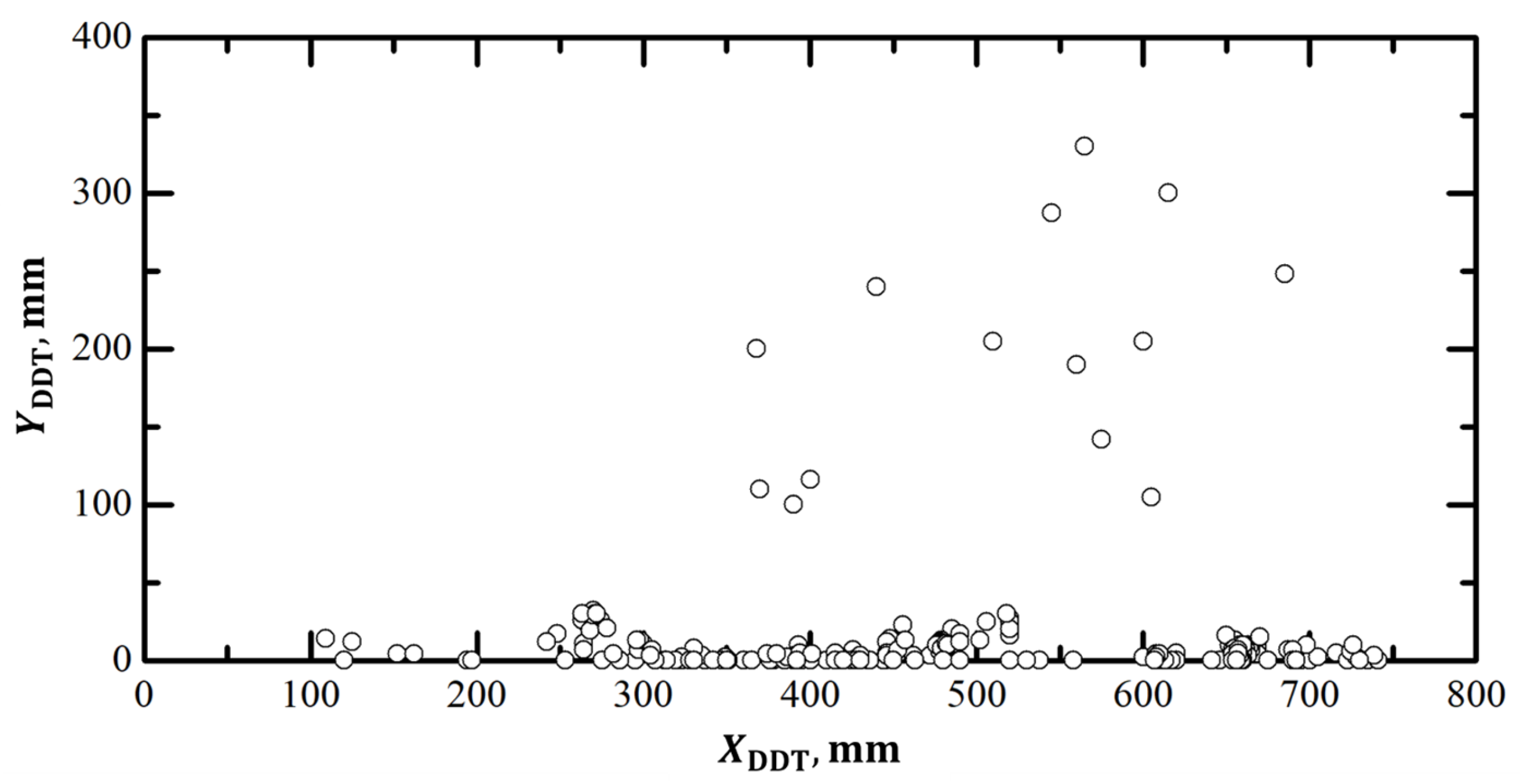
Figure 5 shows a map of DDT locations in all experiments with DDT with the exception of cases when detonation occurred after the reflection of a shock wave from a thin paper wall covering the left end of the slit combustor or outside the slit combustor. In the figure, distances X D D T are measured along the X axis (along the slit bottom) from the closed left end of the slit combustor, and distances Y D D T are measured along the Y axis (along the closed left end of the slit) from the slit bottom. It can be seen that for the studied mixtures, DDT most often occurred at the slit bottom near the fuel and oxidizer supply holes, i.e., in places where turbulence and flame speed were higher. In rare cases, DDT occurred at some distance from the slit bottom due to the curvature of the flame front and due to collision of shock waves generated by the accelerating flame. Taking into account that the combustible mixture was ignited simultaneously along the entire height of the layer and DDT most often occurred close to the slit bottom, it is instructive to compare the X D D T values obtained at different heights of the layer.
Table 2 summarizes information on the DDT probability for the undiluted C2H4 + 3O2 mixture (β = 0, mixture no. 1 in Table 1). Also presented in the table are the minimum and maximum DDT run-up distances along the X axis, X D D T , depending on the layer height. As can be seen, with an increase in the layer height from 80 to 110 mm, the DDT probability increases from 0.3 to 0.7, while a large scatter in X D D T is observed: the minimum X D D T is in the range of 270–385 mm, while the maximum X D D T is in the range of 720–740 mm. The latter values are very close to the value of the right end coordinate, 784 mm. Further increase in the layer thickness increases the DDT probability to 1: in two series of experiments with six and nine repetitions, DDT was recorded in 100% of cases at h e s t = 140–150 mm and h f l a m e = 110–230 mm. In this case, the minimum X D D T value virtually does not change and remains in the range of 250–275 mm, whereas the maximum X D D T value decreases to 450–485 mm. Thus, the scatter of DDT locations is reduced with the distance from the boundaries of the critical “DDT go–DDT no go” curve.
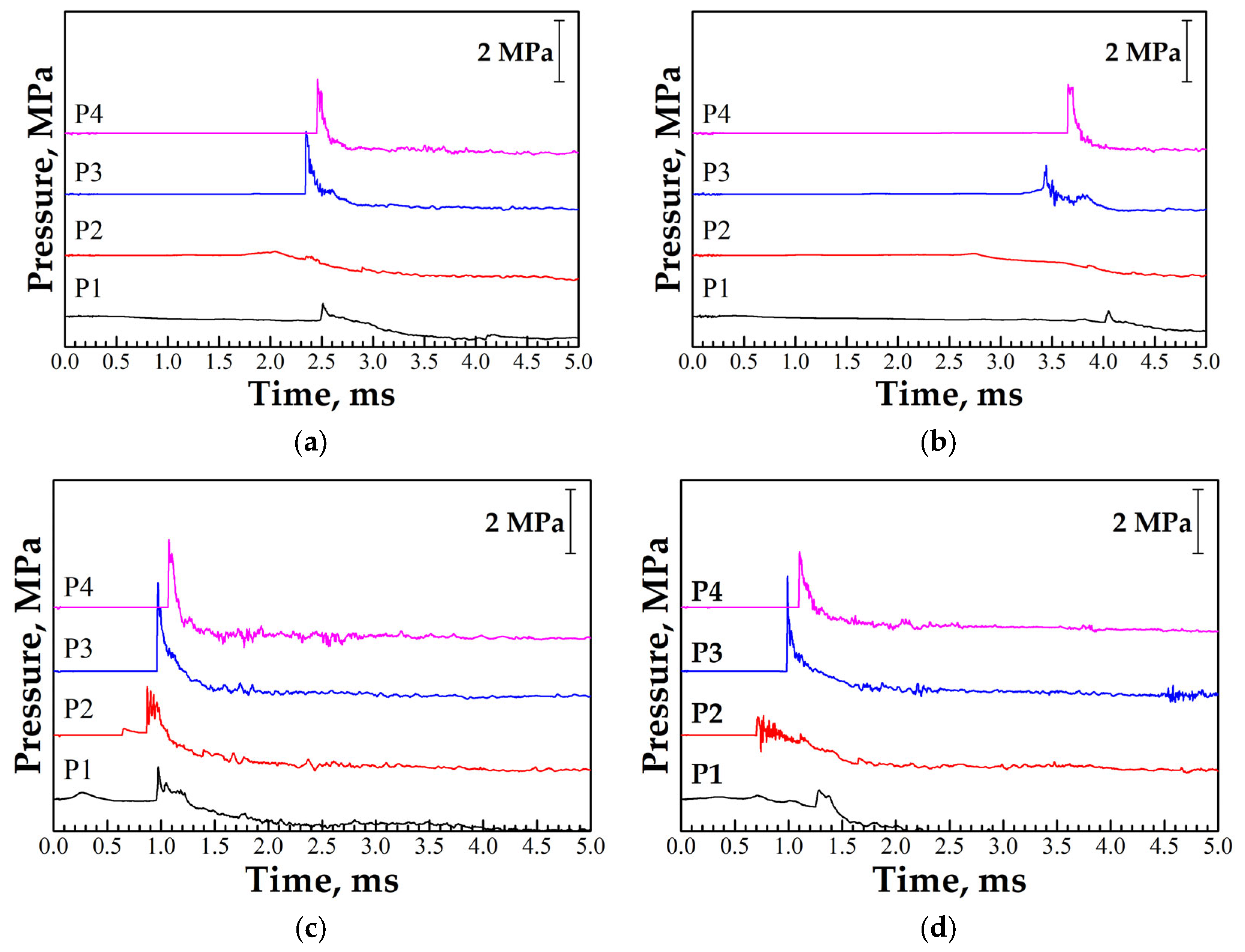
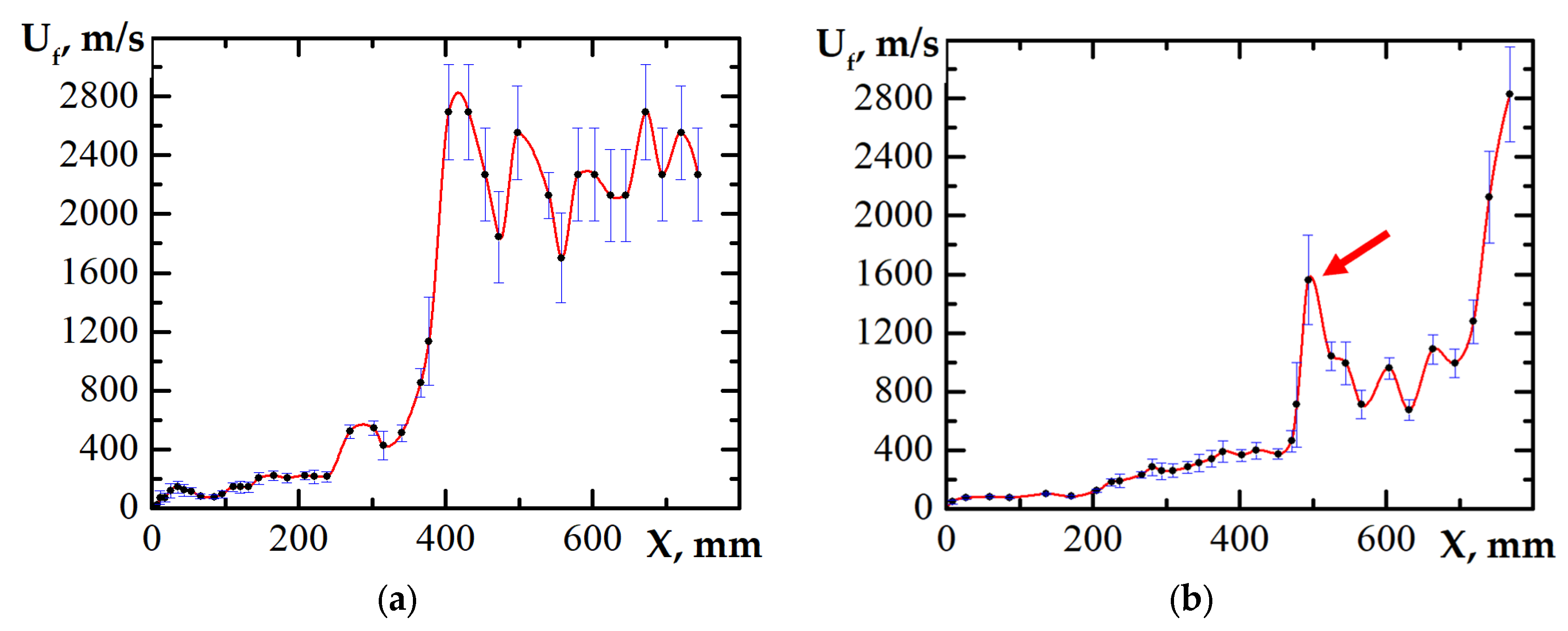
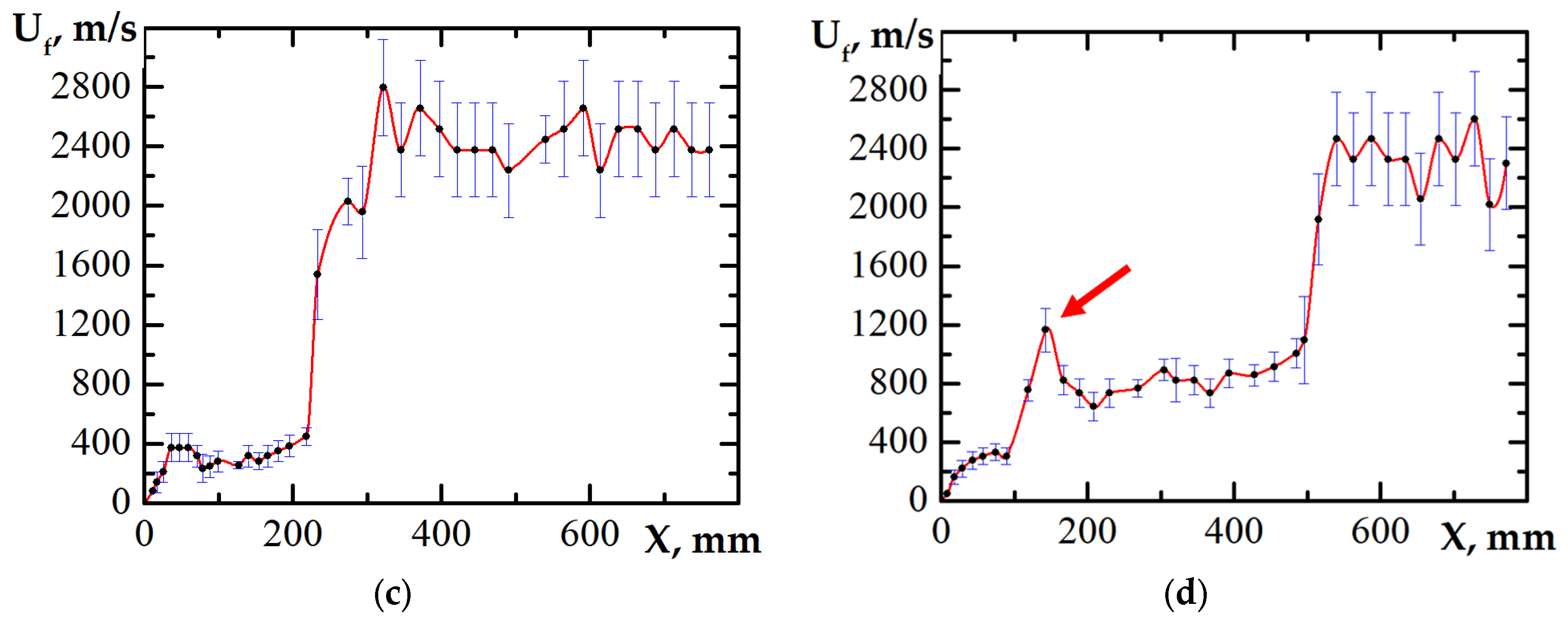
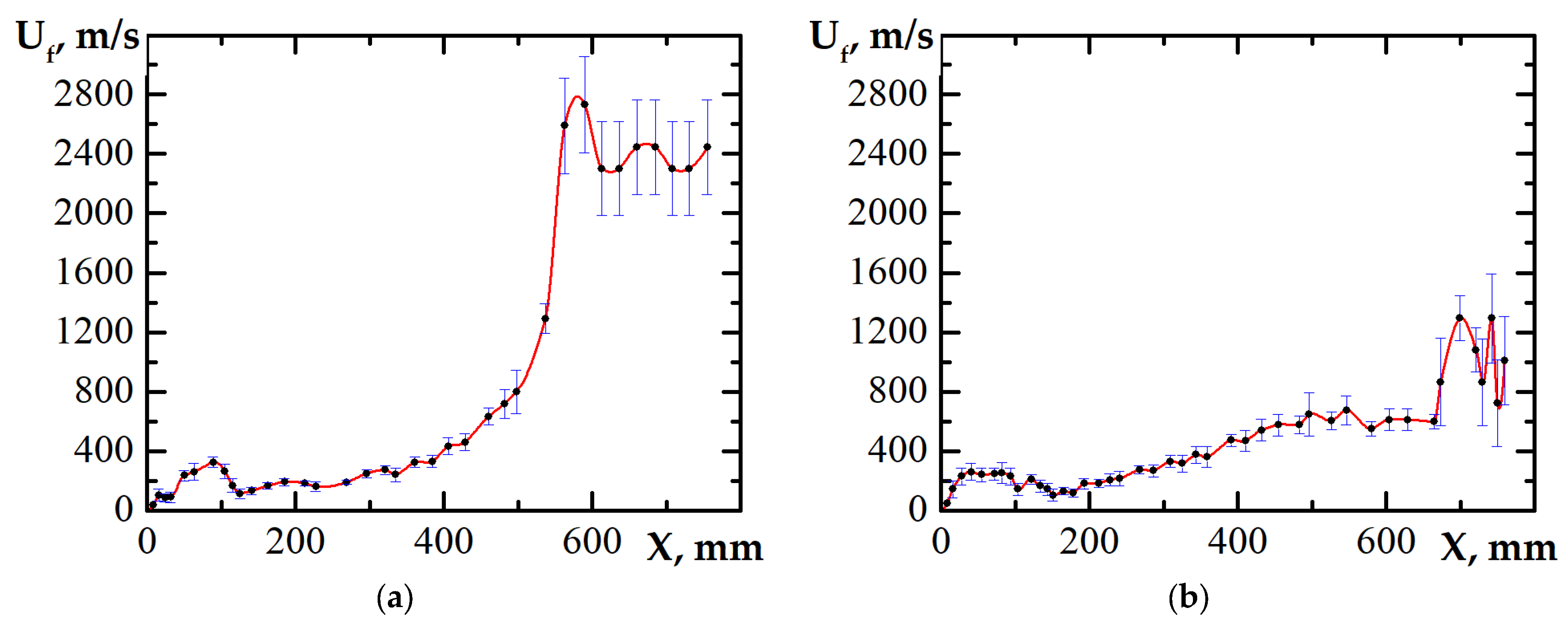
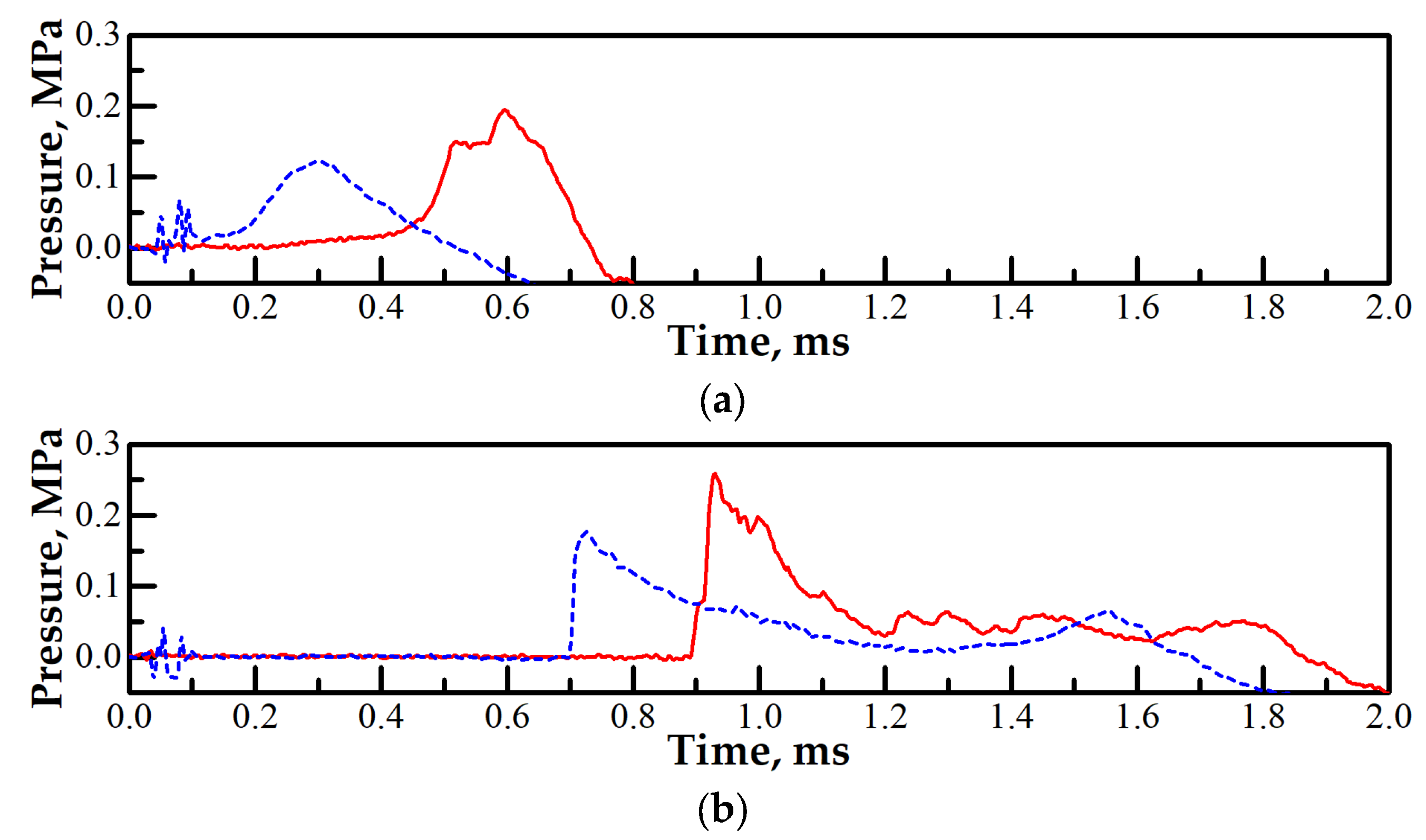
Figure 6 shows pressure records for two experiments with DDT registered in a layer with a height close to the critical (minimum) value with the corresponding minimum (Figure 6a) and maximum (Figure 6b) X D D T values and for two experiments with DDT observed in a twice-higher layer with the corresponding minimum (Figure 6c) and maximum (Figure 6d) X D D T values. The localized explosion giving birth to a detonation occurs at a certain point in the slit combustor. The arising pressure wave propagates in all directions, namely, as a detonation wave in the fresh mixture and as a shock (retonation) wave in the combustion products. Since sensor P1 is located in the vicinity to the left closed end of the slit, it registers nearly simultaneously both the incident and reflected shock waves, which are weaker than the detonation wave registered by sensors P3 and P4. In addition, Figure 7 shows the dependences of the measured velocities of the luminosity front, U f , near the slit bottom on the distance travelled along the X axis. After ignition, a stage of rapid acceleration of the luminosity front is observed: the flame-front velocity quickly increases from zero to a speed close to the speed of sound in the initial mixture. This is followed by an extended stage during which the flame slowly accelerates till detonation occurs via DDT. Interestingly, the flame-front velocity in Figure 7b,d exhibits intermediate peaks (shown by arrows in Figure 7b,d) followed by rapid flame deceleration and relatively slow flame acceleration from about 700 to about 1200 m/s. Careful analysis of video frames shows these peaks correspond to the apparent flame breakthrough along the X axis when the curved flame propagates downward and hits the slit bottom.
The measured detonation velocities for the undiluted C2H4 + 3O2 mixture on average correspond to the thermodynamic value of 2.38 km/s and do not depend on the layer thickness: 2.3 ± 0.3 km/s (Figure 7a) and 2.29 ± 0.06 km/s (Figure 6a); 2.5 ± 0.4 km/s (Figure 7b); 2.46 ± 0.14 km/s (Figure 7c) and 2.46 ± 0.06 km/s (Figure 6c); 2.34 ± 0.17 km/s (Figure 7d); and 2.29 ± 0.06 km/s (Figure 6d). After DDT, the arising detonation wave propagates in a layer whose height is significantly greater than the critical (minimal) height of the layer of gaseous explosive mixture required for the self-sustained detonation propagation according to the criterion [1] (12 ± 5) λ . Taking into account that the detonation cell size for the undiluted C2H4 + 3O2 mixture is λ 0.5–0.8 mm [39,40,41,42,43], the critical height of the layer is 10 ± 4 mm. It is not surprising that, under these circumstances, the detonation velocity in the experiments turns out to be insensitive to the layer thickness. It is interesting that in a number of experiments, detonation propagated in a layer of a combustible mixture with a height of about 10 mm; however, this happened in rare cases when detonation occurred via DDT due to reflection from the right wall covered by thin paper or outside the slit combustor and propagated in the opposite direction (from the open to the closed end of the combustor) along a new layer of the combustible mixture, which had managed to form by this time. Thus, the critical conditions for layer height for DDT and for detonation propagation are fundamentally different.
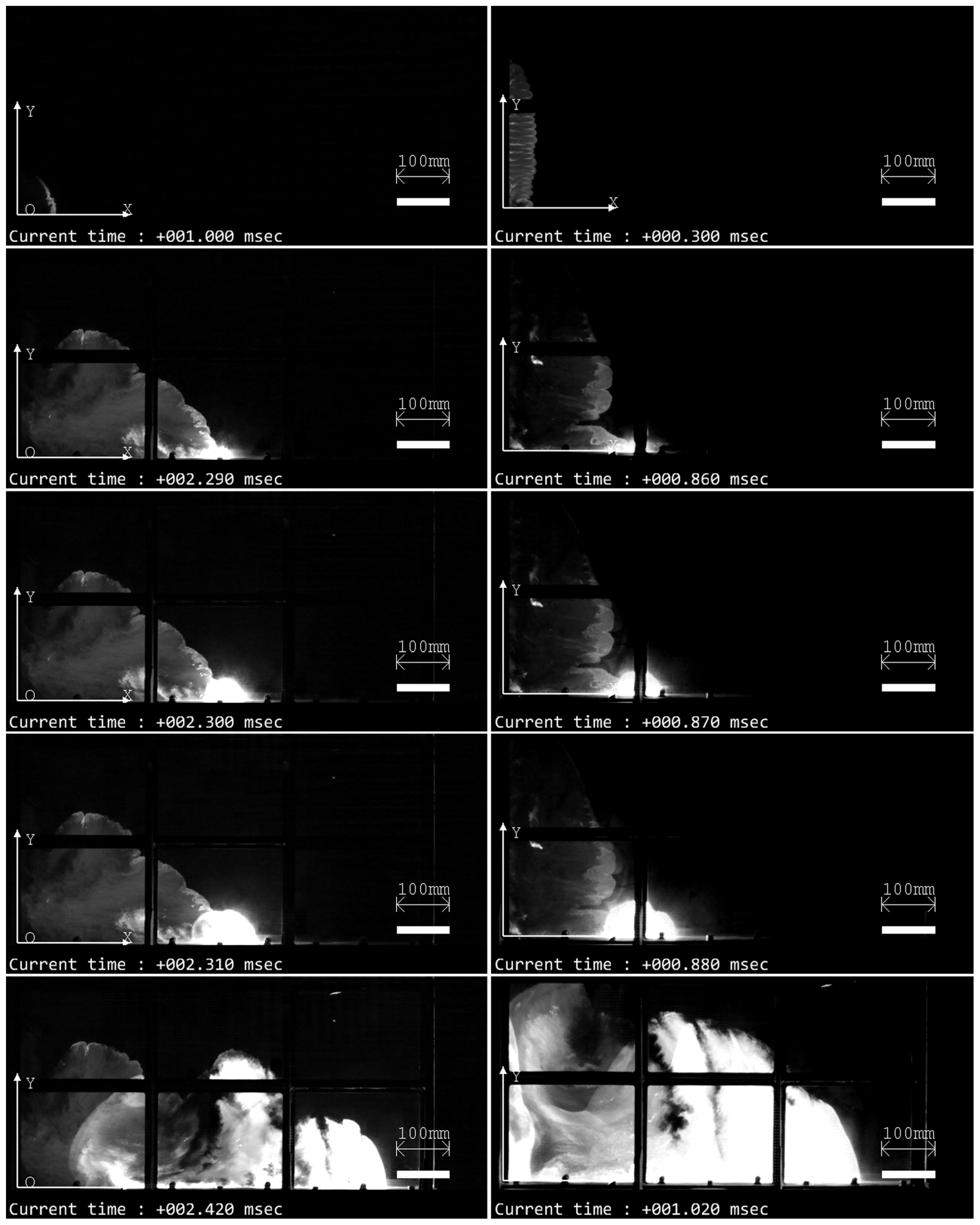
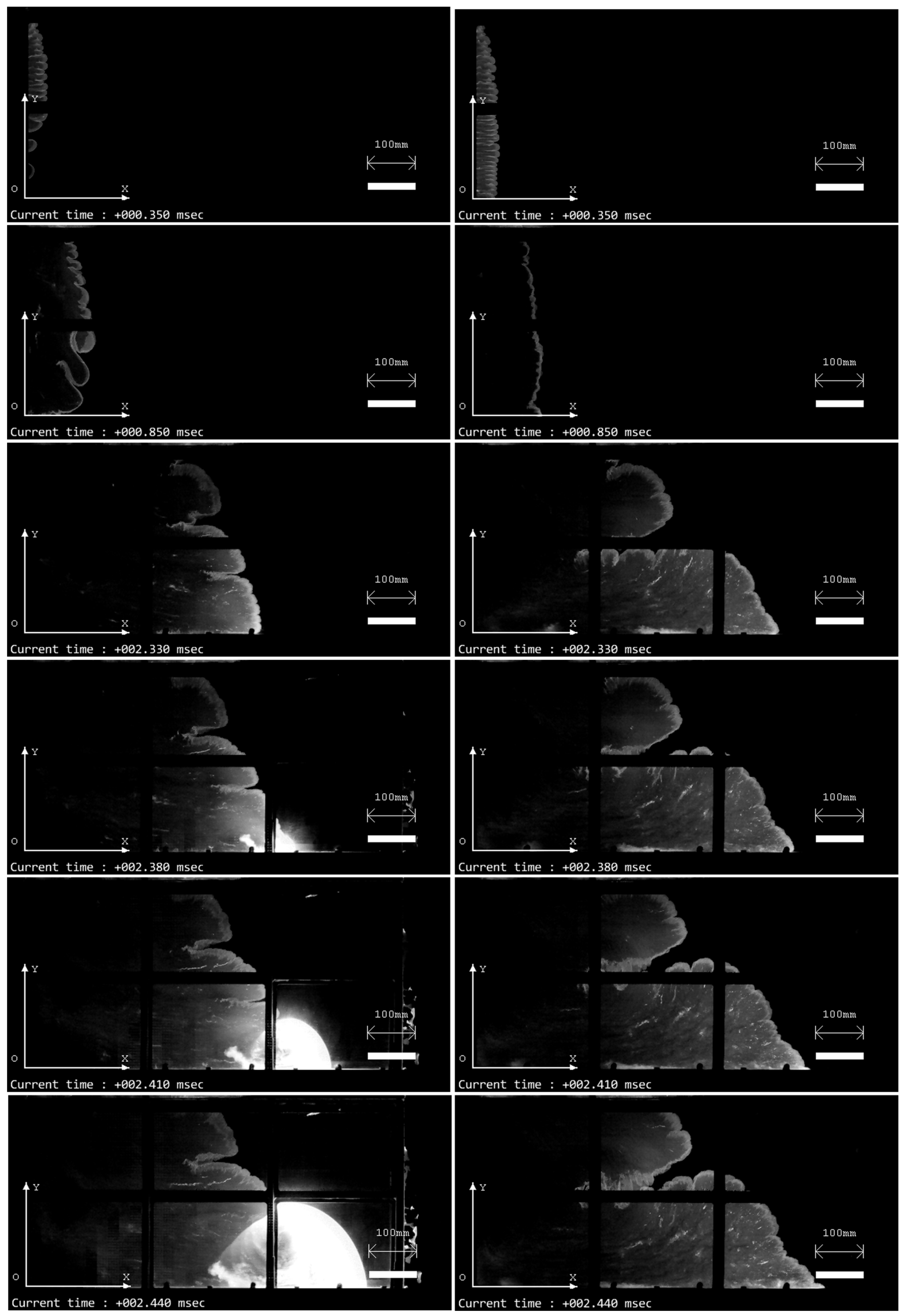
Figure 8 shows video frames of detonation onset via DDT in a layer with a near-critical height of 80 mm and in a layer with a height of 150 mm for mixture no. 1 in Table 1 at the minimum DDT run-up distances. The first line shows frames from which one can judge the height of the layer by the height of the flame front during multifocal ignition: h f l a m e 30 mm in the first case and h f l a m e 220 mm in the second. The second line of the frames is an image of the flame front at the moment of time immediately preceding the DDT. The third line shows video frames immediately after the localized explosions. Further, the fourth and fifth lines show the frames of the detonation wave propagating through the mixture. For comparison, Figure 9 shows similar video frames for experiments in which DDT was observed at the maximum DDT run-up distances.
It follows from Figure 8 and Figure 9 as well as from the analysis of the entire set of experimental data that DDT in a layer of near-critical height is observed mostly at the maximum distances (720–740 mm). However, in contrast to experiments with premixed compositions [26], in experiments with separate supplies of fuel and oxidizer, DDT is also possible at significantly shorter distances (250–400 mm). As the layer height increases above the critical value, there is a tendency for the maximum DDT run-up distance to decrease. DDT most often occurs near the lower boundary of the slit, i.e., in a layer where turbulence and pressure are higher. The insensitivity of the minimum DDT run-up distance to the layer thickness is a consequence of composition inhomogeneity. When the reaction front propagates along the slit bottom, the leading edge of the flame front is located above the injector nozzles, and the shock waves generated by the moving flame front, reflected from the bottom, create favorable conditions for the acceleration of chemical reactions and the formation of a localized hot spot with self-ignition.
Dilution of oxygen with nitrogen by 10% (mixture no. 2 in Table 1) leads to an increase in the critical height of the layer from 80 to 110 mm (see Table 3). The pattern of the experiments in general replicates the pattern observed in experiments with the undiluted mixture. When oxygen is diluted with nitrogen by 16.7% (mixture no. 3 in Table 1) and 20% (mixture no. 4 in Table 1), the critical height of the layer slightly increases: the lower critical height is close to 115 mm (Table 4) and 130 mm (Table 5), respectively. However, taking into account the probabilistic nature of DDT and the finite number of experiments, a conservative estimate of the lower critical height of the layer in both cases is estimated at 120–140 mm. A noticeable increase in the critical height of the layer is observed when β is above 25% (Table 6, Table 7, Table 8 and Table 9).
As noted earlier, DDT is probabilistic in nature due to the inability to accurately reproduce all experimental conditions. The boundaries of the layer are quite blurred and are affected by many factors. Thus, the scatter in the injector nozzle cross sections can cause differences in speeds of fuel and oxidizer jets and their penetration, nonuniformities in mixture composition, etc. As a result, DDT is less likely to occur in a layer whose height is less than a certain critical height but more likely to occur in a layer whose height is larger than the critical height. In fact, according to the data in Table 2, Table 3, Table 4, Table 5, Table 6, Table 7, Table 8 and Table 9, the DDT probability gradually increases from 0 to 1 with the height of the combustible mixture layer. An exception is the case with mixture no. 5 in Table 1, when oxygen is diluted by 25% with nitrogen. In this case, for a layer with a larger height ( h e s t = 219 ± 1 mm), the DDT probability is lower (0.09) than that (0.28) for a layer with a height of h e s t = 172 ± 1 mm. The possible reason for this irregularity is the limited number of experiments under the same initial conditions.

3.2. Effect of Partial Ignition Failure

In some experiments, failures of ignition were observed: there was no ignition at some points, which led to uneven ignition along the height of the layer. In these cases, the flame was ignited by separate individual ignition sources or separate groups of ignition sources. As was mentioned earlier in this paper, the spark gaps were combined into groups of seven spark gaps. Failure of the entire group could be associated with a high breakdown voltage of the discharge gap, when an internal breakdown occurred or, conversely, with a high leakage current, when a sufficiently high potential was not created at the discharge gap, sufficient for the breakdown of the gap. The reason in the latter case was probably due to moisture forming during combustion or moisture entering the slit with air when purged through the slit after combustion. Increasing the time between experiments and monitoring ignition before experiments by repeatedly turning on the ignition module before the experiment and visual monitoring of the operation of the spark gaps reduced the level of such failures. Of particular interest are cases when, after a discharge, one or several ignition centers were formed from a group of spark gaps. Since a group of spark gaps was connected to one ignition coil, sparks occurred at all discharge gaps in the group; however, the flame developed only from some ignition sources. Consequently, in this case, the failure of ignition was associated with a nonuniform mixture at a spark gap. This assumption was confirmed by the increase in the number of such cases as the dilution of oxygen with nitrogen increased. Interestingly, uneven ignition of the mixture along the height of the layer led to the increase in the DDT probability. So, the second line in Table 9 indicates that out of 15 experiments, DDT was observed in 5 experiments; however, out of 15 experiments, only in 6 experiments was ignition uniform, and in all these experiments, DDT was not recorded. In other cases in Table 9, when uneven ignition of the combustible mixture layer was detected, this did not affect the DDT probability. Thus, the influence of the ignition pattern on the DDT probability is manifested only when the layer height is close to the critical value.
Nonuniform ignition of the combustible mixture layer leads to the formation of expanding combustion products and colliding pressure waves. This causes additional disturbances of the flame front and its acceleration at the initial stage of its evolution. Figure 10 shows video frames of two experiments in which the mixture layer is ignited in the first case with misfires and in the second case without misfires (when all spark gaps are triggered simultaneously). For the same two experiments, Figure 11 shows the dependences of the measured flame-front velocity on the travelled distance along the X axis. When plotting the graphs, the position of the flame front was tracked by the lower leading edge of the front. It is important that in the first case, the flame-front velocity reaches a local maximum of 330 m/s at a distance of 90 mm, and in the second case, this occurs at a distance of 40 mm with a local maximum in the flame-front velocity of 260 m/s. In the first case, the minimum velocity is located at X = 130 mm and in the second case at X = 160 mm. The flame-front velocity in both cases is ~100 m/s. As a result, in the first case, with uneven ignition with a delay of ~0.3 ms, a stronger shock wave is formed. Figure 12 shows the time histories of pressure measured by sensors P1 and P2. One can see that sensor P1 in the first case (experiment no. 812) measures the wave amplitude 25% higher than in the second case (experiment no. 813), whereas the difference in wave amplitudes measured by sensor P2 is even higher (40%).
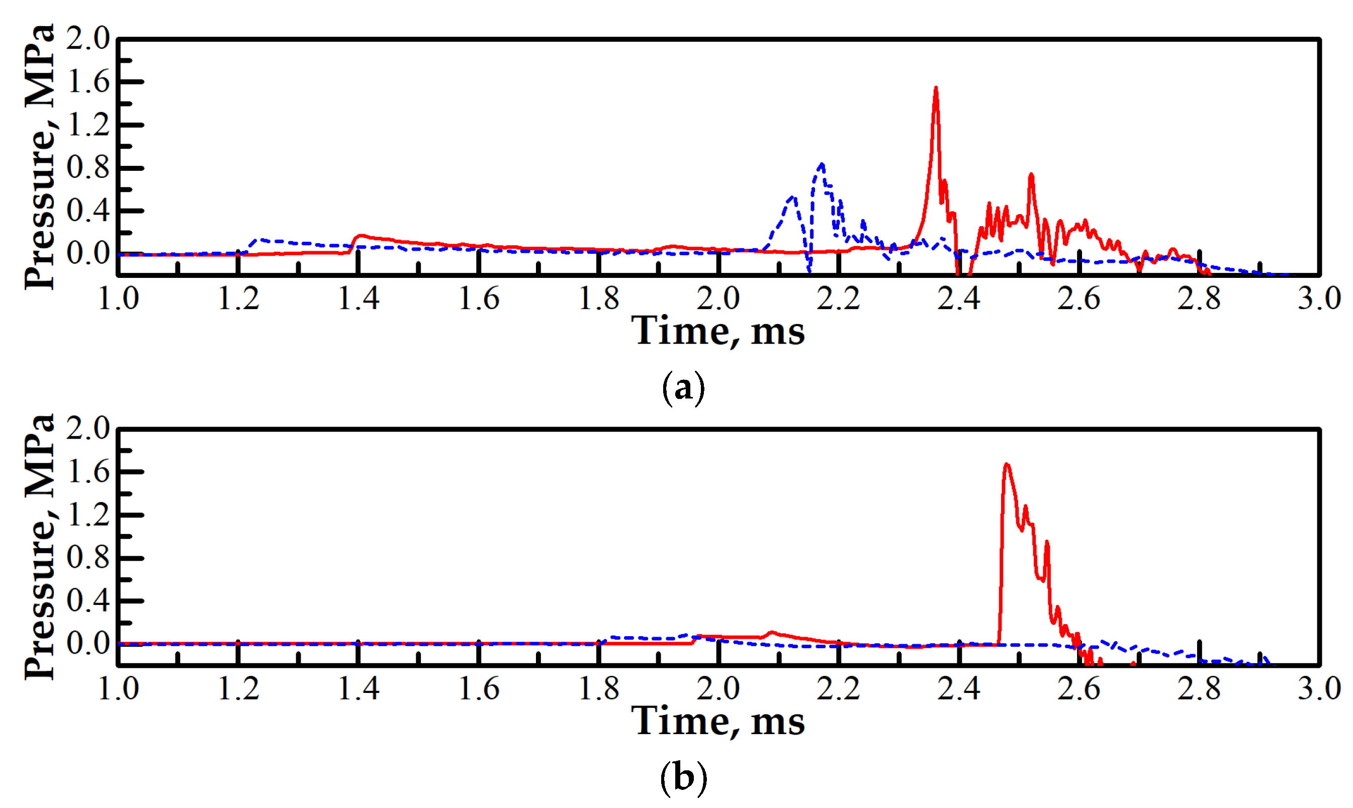
When considering the luminosity intensity at the flame front in Figure 10 (see the third line of images, time 2.33 ms), one can see that in the first case, the reactions proceed at a higher rate than in the second as the luminosity intensity at the slit bottom in the first case is noticeably higher than in the second case. In the first case, the flame front appears as an almost vertical line, whereas in the second, the flame front forms a line with a slope close to 45°. As a result, in experiment no. 812, in contrast to experiment no. 813, conditions are created under which self-ignition of the combustible mixture leading to its detonation is possible. Figure 13 shows the pressure histories measured by sensors P3 and P4 in these experiments. Sensor P3 is located slightly upstream of the DDT location ( X P 3 = 508 mm vs. X D D T = 530 mm). One can see in Figure 13 that the pressure amplitude in the wave in experiment no. 812 before the detonation onset is almost twice higher than in experiment no. 813 with no DDT. The detonation wave in experiment no. 812 and the flame front in experiment no. 813 approach the right end of the slit combustor almost at the same time; however, in the first case, sensor P4 registers a pressure history characteristic of detonation in terms of the pressure profile and amplitude, whereas in the second case it registers only a thermal drift of the signal after flame passes over the sensor.

3.3. Effect of Overall Equivalence Ratio

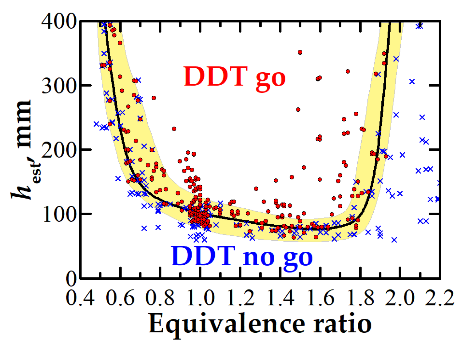
When fuel and oxidizer are supplied separately into the slit combustor, a combustible mixture forms inside the growing layer. As a result, the true composition of the combustible mixture at each point and at each moment in time can differ greatly from its average value. The experiments discussed above were performed for the stoichiometric ratio of the average flow rates of fuel (ethylene) and oxidizer (oxygen diluted with nitrogen). To assess the effect of the overall mixture composition on DDT, we conducted experiments at different ratios of average flow rates of ethylene and oxygen for undiluted C2H4 + 3O2 mixtures. The overall fuel-to-oxidizer equivalence ratio Φ was varied from 0.3 to 2.3. Figure 14 presents the results of the experiments in terms of the “DDT go” and “DDT no go” parametric domains on the h e s t Φ plane. Each symbol on the plot represents a different experiment. Experiments with similar initial parameters form groups of closely spaced symbols. As one can see, there is a domain in which different signs (circles for experiments with DDT and crosses for experiments with no DDT) overlap. This is a transition region in which DDT occurs or does not occur depending on a combination of random factors. This transition domain is shown by a semitransparent band in Figure 14. The mean boundary separating the “DDT go” domain from the “DDT no go” domain is shown by the U-shaped curve. Such a shape of the curve demonstrates the presence of critical conditions for DDT in terms of both the height of the layer and the mixture composition. DDT in the slit combustor was observed at Φ ranging from 0.5 to 1.9. In a wide range of fuel-rich compositions with 1.0 ≤ Φ ≤ 1.8, the critical height of the combustible mixture layer remains almost constant at a level of 70–90 mm. A decrease in Φ to ~0.7 leads to a gradual increase in the critical height of the layer. A further decrease in Φ results in a drastic increase in the critical layer height. When a mixture with a fixed Φ is diluted with nitrogen, a very similar pattern is observed. In general, such dependences are caused by an increase in the characteristic time of chemical transformation and therefore a progressive increase in energy losses.
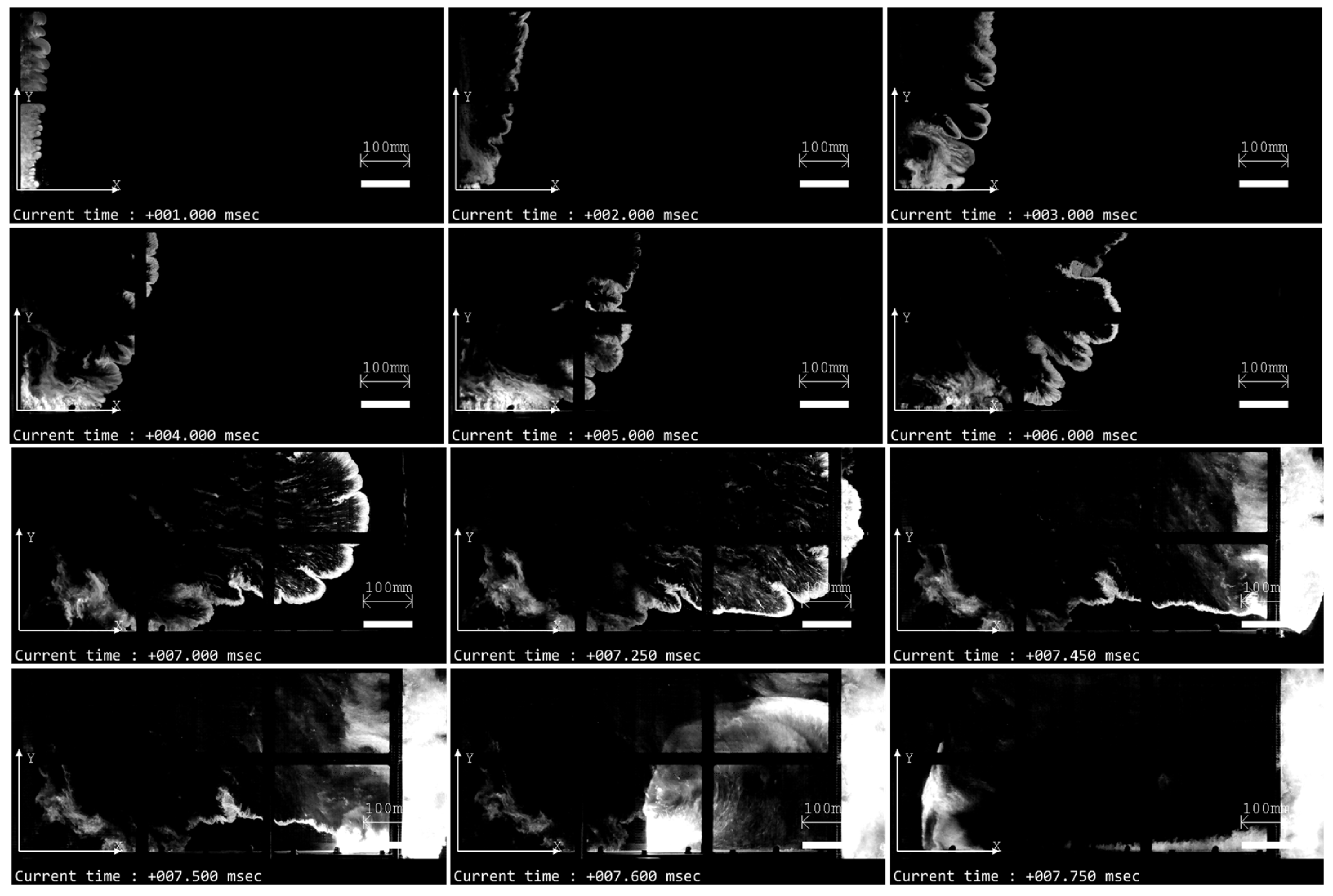
For fuel-rich mixtures, an increase in the height of the layer results in some interesting changes in the dynamics of flame propagation in the slit. When the initial height of the layer significantly exceeds the critical value, the maximum flame velocity is attained at a sufficient elevation from the slit bottom rather than in the bottom vicinity. Thus, at 1.9 ≤ Φ ≤ 2.2, the flame front often evolves in such a way that a layer of unburnt mixture forms at the slit bottom and the flame front propagates from top to bottom along almost the entire slit length. Figure 15 demonstrates this phenomenon. Initially, the flame spreads slowly. After the rupture of the paper at the right end of the slit combustor, the flame significantly accelerates in the rarefaction wave and exits the slit, giving birth to a detonation wave propagating back to the slit through the near-bottom layer of unreacted mixture. Such cases are characterized by very long times of flame propagation significantly exceeding the characteristic longitudinal acoustic time (800 mm/340 m/s = 2.4 ms). As seen, the time taken for the flame to reach the right end of the slit combustor in Figure 15 is about 7.2 ms.
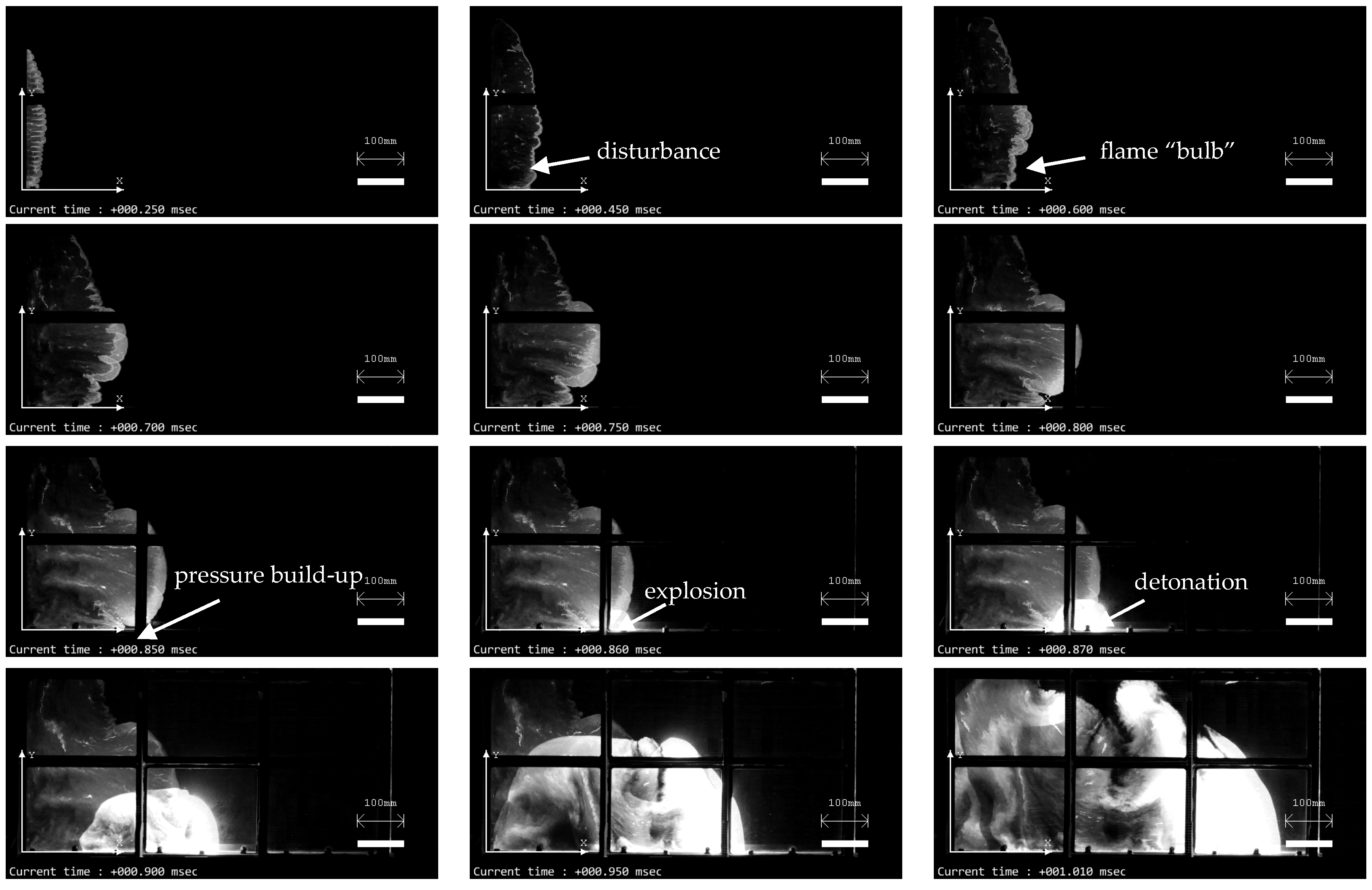
Although in fuel-rich mixtures with 1.5 ≤ Φ < 1.9 the flame propagates somewhat faster, the flow pattern remains quite similar to that observed for the richer mixtures. Initially, the flame moves mainly along the X axis and the flame shape is nearly flat. At a certain time, the central part of the flame accelerates, forming a flame “bulb” growing in all directions. As it approaches the slit bottom, a localized region with elevated pressure and temperature is created in the gap between the flame and the slit bottom. It is in this region that, as a rule, a localized explosion occurs due to the preflame self-ignition of the mixture. Figure 16 and Figure 17 demonstrate these phenomena for fuel-rich 1.8C2H4 + 3O2 and 1.5C2H4 + 3O2 mixtures with Φ = 1.8 and 1.5, respectively. In Figure 16, DDT occurs in t D D T = 1.01 ms at X D D T = 357 mm and Y D D T = 75 mm. In Figure 17, DDT occurs faster (in t D D T = 0.86 ms) at X D D T = 286 mm and Y D D T = 15 mm, i.e., much closer to the slit bottom.

4. Discussion

Figure 18 presents the results of experiments in terms of the “DDT go” and “DDT no go” parametric domains on the [N2]– h e s t plane for C2H4 + 3(O2 + βN2) mixtures of overall stoichiometric composition. With an increase in nitrogen dilution [N2] = β/(1 + β), the maximum height of the mixture layer required for DDT is seen to increase. For mixture no. 9 (see Table 1) with [N2] = 40%, no DDT was registered when the slit was filled with a combustible mixture up to V m / V c > 150%. Note that for the same premixed composition, DDT was registered in one of six experiments with V m / V c > 120% [26]. For mixture no. 8 with [N2] = 37.5%, DDT was observed at h e s t = 380 mm, while in experiments with premixed composition, DDT was observed only when the slit was completely filled with the combustible mixture [26]. When [N2] > 20%, a drastic increase in the critical height of the layer is observed. This is probably caused by the fact that for the mixtures with [N2] > 20%, the detonation cell size exceeds the slit width (6.5 mm). In these conditions, various limiting phenomena associated with heat and momentum losses are expected to manifest themselves and influence the critical layer height [44].
The detonation cell size λ (mm) can be estimated using the polynomial [42]
λ = 0.52 + 1.66 β + 0.29 β 2 + 0.49 β 3
In [42], the approximation for the detonation cell size as a function of nitrogen dilution for ethylene–oxygen–nitrogen mixtures is obtained based on data reported in [39,40]. Figure 19 presents the data of Table 1 for the minimum height of the layer required for DDT in relation to the transverse detonation cell size,   λ (squares). In addition, Figure 19 plots the data from [26] obtained for the homogeneous mixtures (circles). For mixture no. 1 in Table 1, the detonation cell size calculated using the polynomial of Equation (3) is equal to 0.52 mm, while according to the data reported in [43], the detonation cell size is 0.38 mm. Similarly, for mixture no. 6 in Table 1, the detonation cell size calculated using this polynomial is 1.3 mm, while according to the data reported in [40], λ   0.9 mm, i.e., the detonation cell size is known with a large uncertainty. Compared to λ , the critical heights of the layers of mixtures no. 1 and no. 6 in Table 1 are (150…210) λ ( λ   0.52 mm [42] and λ   0.38 mm [43]) and (210…300) λ ( λ   1.3 mm [42] and λ   0.9 mm [40]), respectively. The greatest difference is observed for the undiluted C2H4 + 3O2 mixture, when the critical layer height is minimal. For this mixture, dilution with ambient air during slit fill and mixing nonuniformity play a key role. As the degree of mixture dilution with nitrogen increases, the critical height of the layer increases, but the role of the two factors mentioned above seems to decrease and the results no longer depend on the method of obtaining the combustible mixture. It is worth noting that at large degrees of mixture dilution with nitrogen, the cell size becomes comparable with the slit width. In these conditions, the slit width becomes an additional parameter affecting the detonation cell size [45,46] and the critical height of the layer.
It is interesting to compare available results on the critical height of the layer obtained for nonpremixed and premixed compositions. Compared to experiments with separate supplies of fuel and oxidizer [8], in experiments [26] with the supply of a homogeneous stoichiometric C2H4 + 3O2 mixture, a half-low value was obtained for the critical height of the layer: 50 mm vs. 120 mm. In the present work, DDT was observed at a minimum layer height of 80 mm. Summarizing the results of experiments in this work and in [8] with the results of experiments with premixed compositions [26], one comes to the conclusion that the critical height of the layer is determined by the degree of mixture homogeneity as well as by the degree of dilution of the combustible mixture by the displaced medium (ambient air).
Note that there is a fundamental difference in the critical conditions for detonation propagation and DDT. Thus, experiments with RDEs operating on C2H4–O2 mixtures were reported in [33,34,35,36,37]. In the most recent experiments [37] with the same homogeneous combustible mixture, the height of the detonation wave steadily propagating in the slit between parallel walls was equal to the height of the layer of the combustible mixture in front of the wave (12 mm). In experiments [26] with the same homogeneous combustible mixture, a four-times-greater value was obtained for the critical height of the layer. In experiments [8] with separate supplies of fuel and oxidizer, a 10-times-greater value was obtained for the critical height of the layer of the mixture of the same overall composition. Finally, in the present experiments, the critical height of the layer appears to be seven times greater. Consequently, for a mild start of an RDE with separate supplies of fuel and oxidizer via DDT, it is necessary to fill the combustor to a height at least 7–10 times higher than the height of the detonation waves continuously rotating in the combustor in steady-state engine operation.

5. Conclusions

Detonation initiation in RDEs can be accompanied by a destructive explosion of an excess volume of the fuel mixture in the engine combustor. To exclude this highly undesired phenomenon, a “mild” rather than “strong” initiation of detonation is required. For the mild initiation of detonation in RDEs, it is necessary to ignite a mixture of a certain minimum volume sufficient for DDT. In this study, the critical conditions for detonation initiation through DDT in a semiconfined slit combustor simulating the RDE combustor with a separate supply of ethylene and oxygen diluted with nitrogen (from 0 to 40%) were obtained experimentally for mixtures with the overall fuel-to-oxidizer equivalence ratio Φ varied from 0.3 to 2.3 at normal pressure and temperature conditions. As in our previous studies, the mixture layer was ignited at the closed end of the slit combustor by a linear ignition source along the entire height of the layer. It turned out that for the mild initiation of detonation, it is necessary to ignite the mixture upon reaching the critical (minimum) height of the combustible mixture layer. Since the boundaries of the layer are quite blurred and are affected by many factors, DDT is probabilistic in nature, i.e., DDT is less likely to occur in a layer whose height is less than the critical height but more likely to occur in a layer whose height is larger than the critical height. In the layers of near-critical height, the DDT probability increases at uneven ignition of the mixture along the height of the layer. The mean boundary separating the “DDT go” domain from the “DDT no go” domain at the “layer height–equivalence ratio” plane has a characteristic U-shaped curve, demonstrating the presence of critical conditions for DDT in terms of both the height of the layer and the mixture composition. DDT in the slit combustor was observed at Φ ranging from 0.5 to 1.9. In a wide range of fuel-rich compositions with 1.0 ≤ Φ ≤ 1.8, the critical height of the combustible mixture layer remained almost constant at a level of 70–90 mm. A decrease in Φ to ~0.7 led to a gradual increase in the critical height of the layer, whereas a further decrease in Φ resulted in a drastic increase in the critical layer height. When a mixture with a fixed Φ was diluted with nitrogen, a very similar pattern was observed.
For the mild initiation of detonation in the undiluted C2H4 + 3O2 mixture filling the slit combustor, the height of the mixture layer must exceed the slit width by approximately a factor of 12. In terms of the transverse size of the detonation cell λ , the minimum layer height of such mixtures in experiments is about 150 λ . Compared to the experiments with the premixed composition, the critical height of the layer is 20% larger, which is explained by the finite rate of mixing. As the degree of oxygen dilution with nitrogen increases, the critical height of the layer increases, and the role of finite rate mixing decreases; the result no longer depends on the method of combustible mixture formation.
Future work will be focused on the concentrated rather than distributed ignition of the layer.

Author Contributions

Conceptualization, S.M.F.; methodology, S.M.F. and I.O.S.; investigation, I.O.S., V.S.I., V.S.A., P.A.G. and K.A.A.; resources, S.M.F.; data curation, I.O.S. and K.A.A.; writing—original draft preparation, S.M.F. and I.O.S.; writing—review and editing, S.M.F.; supervision, S.M.F.; project administration, S.M.F.; funding acquisition, S.M.F. All authors have read and agreed to the published version of the manuscript.

Funding

The work was supported by the Ministry of Science and Higher Education of Russia (State contract no. 13.1902.21.0014-prolongation, agreement no. 075-15-2020-806).

Data Availability Statement

Data will be available on request.

Conflicts of Interest

The authors declare no conflict of interest.

References

  1. Bykovskii, F.A.; Zhdan, S.A.; Vedernikov, E.F. Continuous spin detonations. J. Propuls. Power 2006, 22, 1204–1216. [Google Scholar] [CrossRef]
  2. Rankin, B.A.; Fotia, M.L.; Naples, A.G.; Stevens, C.A.; Hoke, J.L.; Kaemming, T.A.; Theuerkauf, S.W.; Schauer, F.R. Overview of Performance, Application, and Analysis of Rotating Detonation Engine Technologies. J. Propuls. Power 2017, 33, 131–143. [Google Scholar] [CrossRef]
  3. Zhou, R.; Wu, D.; Wang, J.-P. Progress of continuously rotating detonation engines. Chin. J. Aeronautics 2016, 29, 15–29. [Google Scholar] [CrossRef]
  4. Anand, V.; Gutmark, E. Rotating detonation combustors and their similarities to rocket instabilities. Prog. Energy Combust. Sci. 2019, 73, 182–234. [Google Scholar] [CrossRef]
  5. Wang, G.; Liu, W.; Liu, S.; Zhang, H.; Peng, H.; Zhou, Y. Experimental verification of cylindrical air-breathing continuous rotating detonation engine fueled by non-premixed ethylene. Acta Astronaut. 2021, 189, 722–732. [Google Scholar] [CrossRef]
  6. Heister, S.D.; Smallwood, J.; Harroun, A.; Dille, K.; Martinez, A.; Ballintyn, N. Rotating Detonation Combustion for Advanced Liquid Propellant Space Engines. Aerospace 2022, 9, 581. [Google Scholar] [CrossRef]
  7. Lee, J.H.S. The Detonation Phenomenon; The Cambridge University Press: New York, NY, USA, 2008. [Google Scholar]
  8. Shamshin, I.O.; Ivanov, V.S.; Aksenov, V.S.; Gusev, P.A.; Frolov, S.M. Experimental study of the initial stage of the operation process in detonation rocket and air-breathing engines. In Advances in Detonation Research; Frolov, S.M., Ed.; Torus Press: Moscow, Russia, 2022; pp. 17–20. [Google Scholar] [CrossRef]
  9. Voitsekhovskii, B.V. Stationary detonation. Dokl. Akad. Nauk. SSSR 1959, 129, 1254–1256. [Google Scholar]
  10. Sommers, W.P.; Morrison, R.B. Simulation of condensed-explosive detonation phenomena with gases. Phys. Fluids 1962, 5, 241–248. [Google Scholar] [CrossRef]
  11. Dabora, E.K.; Nicholls, J.A.; Morrison, R.B. The influence of a compressible boundary on the propagation of gaseous detonations. Proc. Combust. Inst. 1965, 10, 817–830. [Google Scholar] [CrossRef]
  12. Adams, T.G. Do weak detonation waves exist? AIAA J. 1978, 16, 1035–1040. [Google Scholar] [CrossRef]
  13. Ivanov, M.F.; Fortov, V.E.; Borisov, A.A. Numerical simulation of the development of a detonation in gas volumes of finite thickness. Combust. Explos. Shock Waves 1981, 17, 332–338. [Google Scholar] [CrossRef]
  14. Reynaud, M.; Virot, F.; Chinnayya, A. A computational study of the interaction of gaseous detonations with a compressible layer. Phys. Fluids 2017, 29, 056101. [Google Scholar] [CrossRef]
  15. Liu, J.C.; Liou, J.J.; Sichel, M.; Kauffman, C.W.; Nicholls, J.A. Diffraction and transmission of a detonation into a bounding explosive layer. Proc. Combust. Inst. 1988, 21, 1639–1647. [Google Scholar] [CrossRef]
  16. Tonello, N.A.; Sichel, M.; Kauffman, C.W. Mechanisms of detonation transmission in layered H2-O2 mixtures. Shock Waves 1995, 5, 225–238. [Google Scholar] [CrossRef]
  17. Oran, E.S.; Jones, D.A.; Sichel, M. Numerical simulation of detonation transmission. Proc. R. Soc. Lond. A 1992, 436, 267–297. [Google Scholar] [CrossRef]
  18. Ishii, K.; Kojima, M. Propagation of detonation in mixtures with concentration gradients. In Application of Detonation to Propulsion; Roy, G., Frolov, S., Shepherd, J., Eds.; Torus Press: Moscow, Russia, 2004; pp. 32–37. [Google Scholar]
  19. Calhoon, W.; Sinha, N. Detonation wave propagation in concentration gradients. In Proceedings of the 43rd AIAA Aerospace Sciences Meeting and Exhibit, Reno, NV, USA, 10–13 January 2005. [Google Scholar] [CrossRef]
  20. Ishii, K.; Kojima, M. Behavior of detonation propagation in mixtures with concentration gradients. Shock Waves 2007, 17, 95–102. [Google Scholar] [CrossRef]
  21. Kessler, D.A.; Gamezo, V.N.; Oran, E.S. Gas-phase detonation propagation in mixture composition gradients. Phil. Trans. R. Soc. A 2012, 370, 567–596. [Google Scholar] [CrossRef]
  22. Houim, R.W.; Fievisohn, R.T. The influence of acoustic impedance on gaseous layered detonations bounded by an inert gas. Combust. Flame 2017, 179, 185–198. [Google Scholar] [CrossRef]
  23. Rudy, W.; Kuznetsov, M.; Porowski, R.; Teodorczyk, A.; Grune, J.; Sempert, K. Critical conditions of hydrogen–air detonation in partially confined geometry. Proc. Combust. Inst. 2013, 34, 1965–1972. [Google Scholar] [CrossRef]
  24. Kuznetsov, M.; Yanez, J.; Grune, J.; Friedrich, A.; Jordan, T. Hydrogen combustion in a flat semiconfined layer with respect to the Fukushima Daiichi accident. Nucl. Eng. Des. 2015, 286, 36–48. [Google Scholar] [CrossRef]
  25. Grune, J.; Sempert, K.; Haberstroh, H.; Kuznetsov, M.; Jordan, T. Experimental investigation of hydrogen–air deflagrations and detonations in semiconfined flat layers. J. Loss Prevent. Proc. Ind. 2013, 26, 317–323. [Google Scholar] [CrossRef]
  26. Shamshin, I.O.; Ivanov, V.S.; Aksenov, V.S.; Gusev, P.A.; Frolov, S.M. Deflagration-to-detonation transition in a semi-confined slit combustor filled with nitrogen diluted ethylene-oxygen mixture. Energies 2023, 16, 1098. [Google Scholar] [CrossRef]
  27. Ivanov, V.S.; Shamshin, I.O.; Frolov, S.M. Computational study of deflagration-to-detonation transition in a semi-confined slit combustor. Energies 2023, 16, 7028. [Google Scholar] [CrossRef]
  28. Lemcherfi, A.; Gejji, R.M.; Ayers, Z.M.; Plaehn, E.W.; Perkins, H.D.; Roy, S.; Meyer, T.R.; Fugger, C.A.; Slabaugh, C.D. Effect of injection dynamics on detonation wave propagation in a linear detonation combustor. Proc. Combust. Inst. 2023, 39, 2875–2883. [Google Scholar] [CrossRef]
  29. Liu, H.; Jin, D. Characteristics of injection scheme in linearized RDE. Int. J. Aeron. Space Sci. 2023, 24, 459–466. [Google Scholar] [CrossRef]
  30. Shi, L.; Fan, E.; Shen, H.; Wen, C.-Y.; Shang, S.; Hu, H. Numerical study of the effects of injection conditions on rotating detonation engine propulsive performance. Aerospace 2023, 10, 879. [Google Scholar] [CrossRef]
  31. Wang, Y.; Tian, C.; Yang, P. Effects of ozone addition on multi-wave modes of hydrogen–air rotating detonations. Aerospace 2023, 10, 443. [Google Scholar] [CrossRef]
  32. Zhou, J.; Song, F.; Xu, S.; Yang, X.; Zheng, Y. Investigation of rotating detonation fueled by liquid kerosene. Energies 2022, 15, 4483. [Google Scholar] [CrossRef]
  33. Hansmetzger, S.; Zitoun, R.; Vidal, P. Detonation regimes in a small-scale RDE. In Proceedings of the 26th International Colloquium on the Dynamics of Explosions and Reactive Systems, Boston, MA, USA, 30 July–4 August 2017. [Google Scholar]
  34. Kato, Y.; Ishihara, K.; Matsuoka, K.; Kasahara, J.; Matsuo, A.; Funaki, I. Study of combustion chamber characteristic length in rotating detonation engine with convergent–divergent nozzle. In Proceedings of the 54th AIAA Aerospace Sciences Meeting, San Diego, CA, USA, 4–8 January 2016. [Google Scholar]
  35. Wilhite, J.; Driscoll, R.; George, A.S.; Anand, V.; Gutmark, E.J. Investigation of a rotating detonation engine using ethylene–air mixtures. In Proceedings of the 54th AIAA Aerospace Sciences Meeting, San Diego, CA, USA, 4–8 January 2016. [Google Scholar]
  36. Han, H.-S.; Lee, E.S.; Choi, J.-Y. Experimental investigation of detonation propagation modes and thrust performance in a small rotating detonation engine using C2H4/O2 propellant. Energies 2021, 14, 1381. [Google Scholar] [CrossRef]
  37. Taguchi, T.; Yamaguchi, M.; Matsuoka, K.; Kawasaki, A.; Watanabe, H.; Itouyama, N.; Kasahara, J.; Matsuo, A. Investigation of reflective shuttling detonation cycle by schlieren and chemiluminescence photography. Combust. Flame 2022, 236, 111826. [Google Scholar] [CrossRef]
  38. Nettleton, M.A. Gaseous Detonations; Chapman and Hall: London, UK, 1987. [Google Scholar]
  39. Matsui, H.; Lee, J.H.S. On the measure of the relative detonation hazards of gaseous fuel-oxygen and air mixtures. Proc. Combust. Inst. 1979, 17, 1269–1280. [Google Scholar] [CrossRef]
  40. Moen, I.O.; Donato, M.; Knystautas, R.; Lee, J.H.S. The influence of confinement on the propagation of detonations near the detonability limits. Proc. Combust. Inst. 1981, 18, 1615–1622. [Google Scholar] [CrossRef]
  41. Thomas, G.O. Flame Acceleration and the Development of Detonation in Fuel–Oxygen Mixtures at Elevated Temperature and Pressures. J. Hazard. Mater. 2009, 163, 783–794. [Google Scholar] [CrossRef] [PubMed]
  42. Wu, M.-H.; Kuo, W.-C. Transmission of near-limit detonation wave through a planar sudden expansion in a narrow channel. Combust. Flame 2012, 159, 3414–3422. [Google Scholar] [CrossRef]
  43. Kawasaki, A.; Kasahara, J. A novel characteristic length of detonation relevant to supercritical diffraction. Shock Waves 2020, 30, 1–12. [Google Scholar] [CrossRef]
  44. Zel’dovich, Y.B.; Kompaneeta, A.S. The Theory of Detonation; Gostekhteorizdat Publication: Moscow, Russia, 1955. [Google Scholar]
  45. Monwar, M.; Yamamoto, Y.; Ishii, K.; Tsuboi, T. Detonation propagation in narrow gaps with various configurations. J. Therm. Sci. 2007, 16, 283–288. [Google Scholar] [CrossRef]
  46. Ishii, K.; Monwar, M. Detonation propagation with velocity deficits in narrow channels. Proc. Combust. Inst. 2011, 33, 2359–2366. [Google Scholar] [CrossRef]
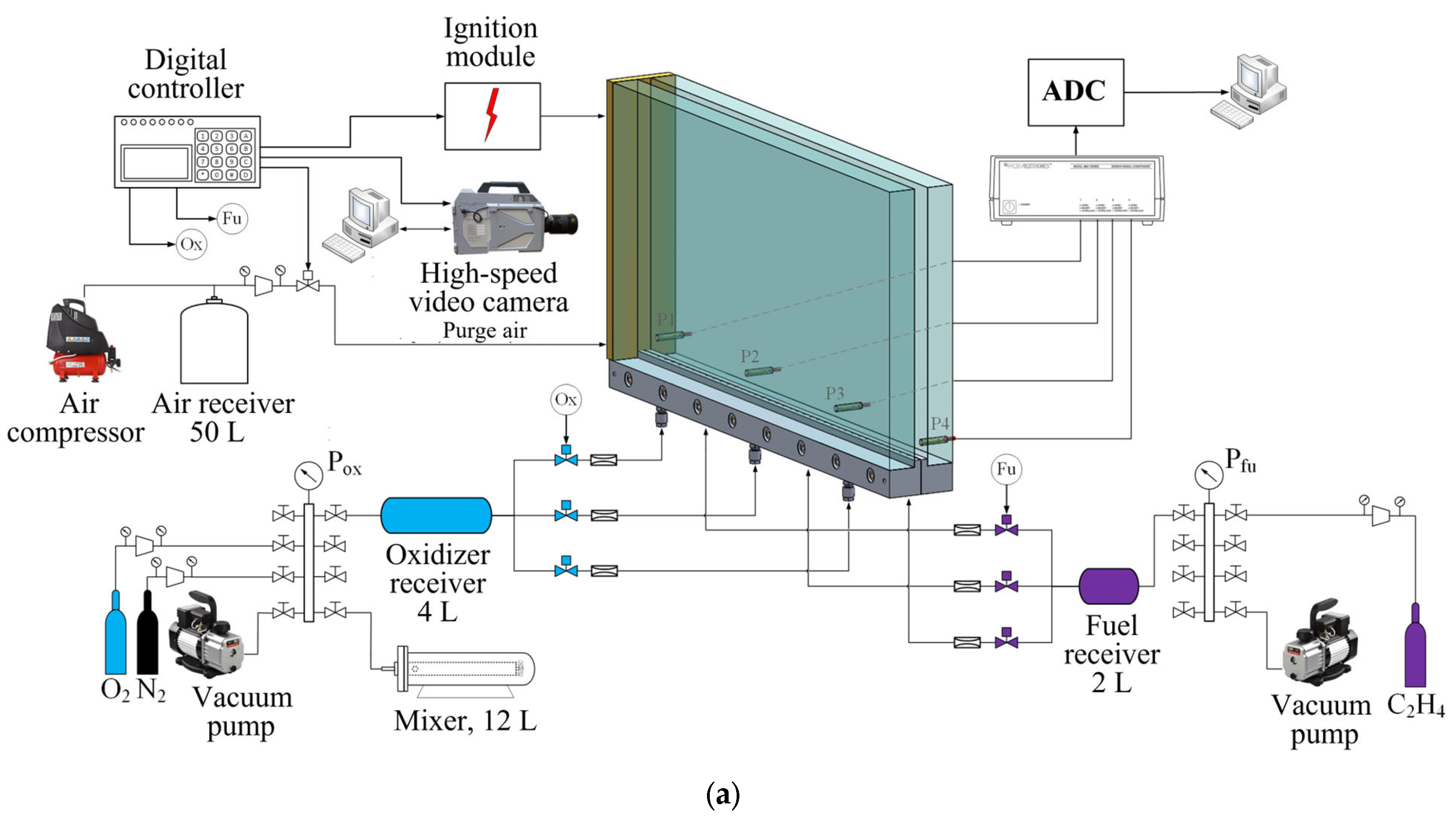
Figure 1. Schematics of experimental setup (a); fuel and oxidizer injectors (b); and the fragment of an insulator with spark gaps (c).
Aerospace 10 00988 g001aAerospace 10 00988 g001b
Figure 2. Typical records of voltage on the solenoid valve coils ( U f u and U o x ) and pressure in the receivers ( P f u and P o x ) for experiment no. 333 with mixture (0.65C2H4 + 3O2); t o n is the delay time for turning on the solenoid valves (9 ms in this experiment); t o f f is the delay time for turning off the solenoid valves (26 ms in this experiment); t s is the switching time (4 ms in this experiment). The time is counted from the ignition.
Aerospace 10 00988 g002
Figure 3. Diagram illustrating the difference between the true height of the combustible mixture layer, h f l a m e , attached to the ignition source and its estimated value, h e s t , based on the assumption of uniform fill. The red solid line corresponds to condition h f l a m e = h e s t .
Aerospace 10 00988 g003
Figure 4. Flow visualization in a slit combustor using MgO particles (experiment no. 426). The images are taken from the central window in the bottom row of three windows. The time interval between images is 10 ms. The time is given in terms of the countdown to ignition.
Aerospace 10 00988 g004
Figure 5. Coordinates ( X D D T , Y D D T ) of DDT locations for the studied mixtures C2H4 + 3(O2 + βN2) with Φ = 1.00 ± 0.06 and 0 ≤ β ≤ 2/3.
Aerospace 10 00988 g005
Figure 6. Examples of experimental pressure records for the layer of near-critical height h e s t = 80 ± 3 mm with X D D T = 385 mm (a) and X D D T = 725 (b) and for the twice-higher layer with h e s t = 153 ± 2 mm with X D D T = 248 mm (c) and X D D T = 485 mm (d).
Aerospace 10 00988 g006
Figure 7. Measured dependences of the luminosity-front velocities, U f , at the slit bottom on the distance travelled along the X axis for the layer of the near-critical height h e s t = 80 ± 3 mm with X D D T = 385 mm (a) and X D D T = 725 (b) and for the twice-higher layer of h e s t = 153 ± 2 mm with X D D T = 248 mm (c) and X D D T = 485 mm (d). Arrows show the flame velocity peaks caused by the apparent flame breakthrough along the X axis.
Aerospace 10 00988 g007aAerospace 10 00988 g007b
Figure 8. Video frames of flame propagation, DDT, and detonation propagation in the slit combustor. On the left: experiment no. 529 with a layer of near-critical height h e s t = 80 ± 3 mm at X D D T = 385 mm, Y D D T = 0 mm, and t D D T = 2.29 ms; on the right: experiment no. 398 for a layer of height h e s t = 153 ± 2 mm at X D D T = 248 mm, Y D D T = 17 mm, and t D D T = 0.86 ms.
Aerospace 10 00988 g008
Figure 9. Video frames of flame propagation, DDT, and detonation propagation in the slit combustor. On the left: experiment no. 530 for a layer of near-critical height h e s t = 80 ± 3 mm at X D D T = 725 mm, Y D D T = 6 mm, and t D D T = 3.63 ms; on the right: experiment no. 120 for a layer of height h e s t = 153 ± 2 mm at X D D T = 485 mm, Y D D T = 20 mm, and t D D T = 0.98 ms.
Aerospace 10 00988 g009
Figure 10. Video frames of flame propagation in a C2H4 + 3(O2 + 3/5 N2) mixture layer of near-critical height h e s t = 380 ± 3 mm. On the left: experiment no. 812 with nonuniform ignition of the mixture along the height of the layer with DDT at X D D T = 530 mm, Y D D T = 0 mm, and t D D T = 2.37 ms. On the right: experiment no. 813 with uniform ignition of the mixture along the height of the layer without DDT.
Aerospace 10 00988 g010
Figure 11. Measured dependences of the flame-front velocities on the distance along the slit bottom during flame propagation in a C2H4 + 3(O2 + 3/5 N2) mixture in a slit combustor with a layer of near-critical height h e s t = 380 ± 3 mm: (a) experiment no. 812, DDT at X D D T = 530 mm, (b) experiment no. 813, no DDT.
Aerospace 10 00988 g011
Figure 12. Pressure histories measured by sensors P1 (a) and P2 (b) in experiment no. 812 (solid curve) and no. 813 (dashed curve).
Aerospace 10 00988 g012
Figure 13. Pressure histories measured by sensors P3 (a) and P4 (b) in experiment no. 812 (solid curve) and no. 813 (dashed curve).
Aerospace 10 00988 g013
Figure 14. Experimental parametric domains “DDT go” and “DDT no go” on the h e s t Φ plane for C2H4–O2 mixture. Circles correspond to “DDT go” domain; crosses correspond to “DDT no go” domain; semitransparent band corresponds to the transition domain; line corresponds to the average boundary separating the “DDT go” and “DDT no go” domains.
Aerospace 10 00988 g014
Figure 15. Video frames of flame propagation in a 2.1C2H4 + 3O2 mixture (experiment no. 234) with h e s t = 215 mm and h f l a m e 350 mm.
Aerospace 10 00988 g015
Figure 16. Video frames of flame propagation and DDT in a 1.8C2H4 + 3O2 mixture (experiment no. 545) with h e s t = 255 mm: t D D T = 1.01 ms, X D D T = 357 mm, Y D D T = 75 mm.
Aerospace 10 00988 g016
Figure 17. Video frames of flame propagation and DDT in a 1.5C2H4 + 3O2 mixture (experiment no. 613) with h e s t = 170 mm: t D D T = 0.86 ms, X D D T = 286 mm, Y D D T = 15 mm.
Aerospace 10 00988 g017
Figure 18. Experimental “DDT go” and “DDT no go” parametric domains on the [N2]– h e s t plane for C2H4 + 3(O2 + βN2) mixtures of overall stoichiometric composition. Filled circles correspond to “DDT go” domain; empty circles correspond to “DDT no go” domain; semifilled circles correspond to the transition domain with the “DDT go” probabilities of 0.1–0.4 and 0.5–0.9, respectively; solid curves correspond to the conditional boundaries of the minimum layer height for “DDT go” based on transition from probability p = 0 to p > 0 and on transition from p < 1 to p = 1 ; dashed line corresponds to the conditional boundary of the minimum layer height for “DDT go” in the homogeneous stoichiometric mixtures [26].
Aerospace 10 00988 g018
Figure 19. The critical height of the layer normalized by the detonation cell size as a function of nitrogen dilution of the C2H4 + 3(O2 + βN2) mixture. Squares correspond to present experiments with nonpremixed compositions; circles correspond to experiments [26] with premixed compositions.
Aerospace 10 00988 g019
Table 1. Combustible mixtures C2H4 + 3(O2 + βN2) and their calculated and measured parameters.
No.βN2,
%
D C J ,
m/s
D 34 ,
m/s
P C J ,
bar
P ,
bar
h m i n ,
mm
h m i n  1,
mm
10023762372 ± 8433.912.9–35.68050
21/91023312306 ± 8632.416.4–33.59565
31/516.722992365 ± 6231.414.2–29.611080
41/42022832386 ± 8330.914.2–35.1120110
51/32522592371 ± 3130.217.6–35.6170200
62/528.622402421 ± 12829.615.8–33.7270 (290)290
71/233.322152415 ± 028.813.5–25.9290 (360)390
83/537.52191428.115.7–35.3>400 2>400 2
92/3402177427.623.1–25.63>400 2
1 Experiments with premixed compositions [27], 2 DDT at V m / V c > 100%, 3 no DDT at a maximum fill V m / V c = 150%, 4  X D D T > X P 3 .
Table 2. DDT probability and measured minimum and maximum DDT run-up distances depending on the layer height for the undiluted C2H4 + 3O2 mixture.
No. h e s t ,
mm
h f l a m e ,
mm
Number of Runs with DDT Minimum   X D D T , mm Maximum   X D D T , mm
Number of Runs in the Series
165 ± 3127 ± 260/7
280 ± 394 ± 374/13385725
391 ± 2122 ± 2615/29282741
4101 ± 4128 ± 4227/37297739
5109 ± 3132 ± 2618/25270723
6140 ± 2196 ± 326/6275450
7153 ± 2163 ± 509/9248485
Table 3. DDT probability and the minimum and maximum DDT run-up distances depending on the height of the layer of C2H4 + 3(O2 + 1/9 N2) mixture.
No. h e s t ,
mm
h f l a m e ,
mm
Number of Runs with DDT Minimum   X D D T , mm Maximum   X D D T , mm
Number of Runs in the Series
172 ± 141 ± 90/3
289 ± 1103 ± 390/5
3111 ± 1100 ± 504/7448730
4152 ± 1191 ± 328/8305670
5191 ± 1163 ± 503/3242263
Table 4. DDT probability and the minimum and maximum DDT run-up distances depending on the height of the layer of C2H4 + 3(O2 + 1/5 N2) mixture.
No. h e s t ,
mm
h f l a m e ,
mm
Number of Runs with DDT Minimum   X D D T , mm Maximum   X D D T , mm
Number of Runs in the Series
195 ± 1118 ± 150/7
2116 ± 1116 ± 61/5641
3137 ± 1139 ± 92/5610669
4186 ± 1180 ± 135/5482656
5236 ± 1241 ± 85/5380478
Table 5. DDT probability and the minimum and maximum DDT run-up distances depending on the height of the layer of C2H4 + 3(O2 + 1/4 N2) mixture.
No. h e s t ,
mm
h f l a m e ,
mm
Number of Runs with DDT Minimum   X D D T , mm Maximum   X D D T , mm
Number of Runs in the Series
1106 ± 1132 ± 80/5
2137 ± 1145 ± 182/7658665
3187 ± 1199 ± 224/8650726
4237 ± 1250 ± 187/7330610
5284 ± 2293 ± 75/5392608
Table 6. DDT probability and the minimum and maximum DDT run-up distances depending on the height of the layer of C2H4 + 3(O2 + 1/3 N2) mixture.
No. h e s t ,
mm
h f l a m e ,
mm
Number of Runs with DDT Minimum   X D D T , mm Maximum   X D D T , mm
Number of Runs in the Series
1127 ± 1146 ± 190/8
2172 ± 1174 ± 162/7482664
3219 ± 1227 ± 91/11655
4263 ± 2288 ± 233/7394610
5292 ± 1285 ± 146/7457670
6308 ± 1326 ± 95/5342661
7352 ± 2365 ± 64/4446657
Table 7. DDT probability and the minimum and maximum DDT run-up distances depending on the height of the layer of C2H4 + 3(O2 + 2/5 N2) mixture.
No. h e s t ,
mm
h f l a m e ,
mm
Number of Runs with DDT Minimum   X D D T , mm Maximum   X D D T , mm
Number of Runs in the Series
1225 ± 1224 ± 100/5
2273 ± 1258 ± 200/5
3301 ± 1281 ± 236/14420662
4327 ± 1304 ± 137/12428663
5389 ± 4345 ± 2610/14392660
6406 ± 6358 ± 253/3510575
Table 8. DDT probability and the minimum and maximum DDT run-up distances depending on the height of the layer of C2H4 + 3(O2 + 1/2 N2) mixture.
No. h e s t ,
mm
h f l a m e ,
mm
Number of Runs with DDT Minimum   X D D T , mm Maximum   X D D T , mm
Number of Runs in the Series
1243 ± 1226 ± 230/7
2289 ± 1280 ± 255/13656690
3362 ± 1318 ± 286/8490659
4388 ± 2329 ± 204/7430660
Table 9. DDT probability and the minimum and maximum DDT run-up distances depending on the height of the layer of C2H4 + 3(O2 + 3/5 N2) mixture.
No. h e s t ,
mm
h f l a m e ,
mm
Number of Runs with DDT Minimum   X D D T , mm Maximum   X D D T , mm
Number of Runs in the Series
1333 ± 1320 ± 120/9
2380 ± 3346 ± 240 (5)/15530692
3425 ± 1366 ± 342/5580656
4470 ± 1384 ± 186/11520667
Disclaimer/Publisher’s Note: The statements, opinions and data contained in all publications are solely those of the individual author(s) and contributor(s) and not of MDPI and/or the editor(s). MDPI and/or the editor(s) disclaim responsibility for any injury to people or property resulting from any ideas, methods, instructions or products referred to in the content.