Article

Development and Calibration of a Three-Directional High-Energy Particle Detector for FY-3E Satellite

1
National Space Science Center, Chinese Academy of Sciences, Beijing 100190, China
2
Beijing Key Laboratory of Space Environment Exploration, Beijing 100190, China
3
Key Laboratory of Space Weather, National Satellite Meteorological Center, China Meteorological Administration, Beijing 100081, China
4
Innovation Center for FengYun Meteorological Satellite (FYSIC), Beijing 100081, China
5
Shanghai Institute of Satellites Engineering, Shanghai 201109, China
*
Author to whom correspondence should be addressed.
Aerospace 2023, 10(2), 173; https://doi.org/10.3390/aerospace10020173
Submission received: 25 December 2022 / Revised: 4 February 2023 / Accepted: 9 February 2023 / Published: 13 February 2023
(This article belongs to the Special Issue Meteorological Satellites Data Analysis)

Abstract

:
According to the characteristics of the LEO space particles radiation environment of China’s Fengyun No. 3 (FY-3) polar-orbiting meteorological satellites, in order to monitor the characteristics, and space–time distribution of charged particle radiation in the orbit space, it is proposed to install a three-directional high-energy particle detector (HEPD) in the three vertical orthogonal directions of FY-3E, so as to carry out the energy spectrum and flux observation of high-energy protons and electrons in the three directions of the satellite, namely, −X, +Y, and −Z. The on-orbit detection data acquired by these payloads can be used for space environment modeling and solar-terrestrial physics research, and provide data sources for operational space environment weather warning and forecasting. Through the ground accelerator calibration experiment and simulation analysis of the three-directional HEPDs developed in the flight model phase, the experimental results show that all the HEPDs’ measured values meet the requirements for technical indexes, such as the detection energy range (high-energy protons: 3–300 MeV; high-energy electrons: 0.15–5.7 MeV), energy span accuracy (<15%), flux accuracy (<15%), and sensitivity (<5% (ΔN/N)).

1. Introduction

The Fengyun No.3 (FY-3) meteorological satellite is the second generation of China’s polar-orbiting meteorological satellite series that realizes global, all-weather, multispectral, three-dimensional, and quantitative remote sensing, including three batches in total. Among them, the third batch aims at the advanced level of international development of meteorological satellites, realizes the operation of the multi-satellite networking of China’s second-generation polar-orbiting meteorological satellites, and drive its application into a mature development stage [1,2,3,4,5].
The HEPD is one of the remote sensing instruments on the FY-3E satellite, which is the first satellite in 03 batches, and was launched in July 2021, consisting of six space environment detection payloads: high-energy particle detector, intermediate-energy proton detector, intermediate-energy electron detector, radiation dosimeter, magnetic field detector, and potential detector. Monitoring and warnings of the space environment are some of the important measures to ensure the life of astronauts and the safety of spacecraft on-orbit operations [6,7,8,9]. They also hold great significance for the normal operation of systems, such as wireless communication, navigation and positioning [10,11,12,13], aircraft, and ground power grids in the mid–high latitudes. Space environment detection also provides important scientific data for climate and meteorological research [14,15], solar-terrestrial physics research [16], and experiments.
For the characteristics of the space particle environment in the orbit of the FY-3 satellite, this study reports the design and development of a three-directional high-energy particle detector on the FY-3E satellite, and conducts the energy spectrum and flux observations of space high-energy protons and electrons in multiple directions [17] in this orbit for the first time. Generally, for charged particle detectors on satellites, most of them are detected in one direction, or rarely two kinds of charged particles are measured simultaneously on the same load [18,19].

2. Main Technical Indexes

The FY-3 satellite operates in a sun-synchronous orbit of 830 km, which is located at the edge of the inner radiation belt. When the space environment is in a quiet period, the particles in this orbit are distributed in the negative magnetic anomaly region of the South Atlantic Ocean. When the space environment is disturbed, there will also be particle distribution in the high latitudes, and the particles including mainly protons and electrons [20,21,22,23,24].
The main detection objects of the HEPD are the high-energy particles in the radiation belt. The detection content is the energy spectrum and flux of high-energy protons and electrons in three orthogonal directions of the satellite, direction of satellite retreating −X, direction towards the sky +Y, and direction of perpendicular to the orbital plane −Z. By detecting the energy spectrum and flux of charged particles, their time-varying spatial distribution can be obtained, providing information on the motion-low of high-energy particles. This can provide detection data for the space environment security monitoring and system of China, and also provide analysis data for satellite flight control management and abnormal situation analysis.
The main technical indexes of the HEPD on the FY-3E satellite are shown in Table 1.
In this table, the energy range represents the energy of incident particles that can be measured by the instrument. The detection field represents the field of view of incident particles that the instrument can accept. In addition, sensitivity refers to the minimum space environment change that can cause a one-count change in it.

3. System Composition

The HEPD includes four single units. There are three high-energy probes and a shared electronics box. Each probe includes a high-energy proton probe and a high-energy electron probe. The system scheme composition is shown in Figure 1.
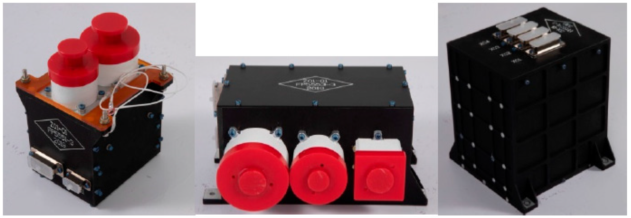
The three probes of the HEPD are installed on three mutually perpendicular planes of the satellite to realize the measurement of high-energy protons and electrons in three orthogonal directions. The three probes are connected to the electronics box through the cross-cabin cables inside the satellite, and the data processing unit processes the signals of the six probes. Figure 2 below shows the photos of HEPD.
A collimating structure, added outside the HEPD, limits the detection field of view of the instrument. Furthermore, the shielding effect of the collimating structure is applied to reduce the interference ratio of obliquely incident particles (high-energy protons and electrons). Combined with the field of view limited by the collimator and the actual size and shielding conditions of the instrument, the final geometric factor of the instrument can be obtained by adopting the method of Monte Carlo simulation, which is used as the basis for later data processing. The geometric factor is an important characteristic parameter of the detector. It is necessary for data normalization and data comparison.
The semiconductor detector measurement system is the key part of the entire instrument, and it measures the energy spectrum of high-energy particles in the form of a telescope formed by stacking multiple pieces of a silicon semiconductor. The energy spectrum of space particles is determined by analyzing the signal amplitude of each sensor in the measurement system and combining with a reasonable logical working mode.
The electronics system collects the signals of the sensors, executes the logical working mode in the physical design, divides and counts the electronic energy spectrum, and, finally, packs the data and communicates with the satellite.

4. Instrument Design

4.1. Fundamental Principle

The basic detection principle of the HEPD is as follows. Both high-energy proton and electron probe systems use silicon semiconductor detectors. When high-energy particles are injected into the sensor through the collimator, they deposit energy in each semiconductor detector and generate corresponding electron–hole pairs in an ionization mode. Under the action of a high-voltage electric field, these electron–hole pairs are assembled to the output terminal and generate charge pulses. The charge pulse height is proportional to the energy deposited by the particles in the semiconductor detector. According to the pulse height of the semiconductor detector, the signals are subjected to discrimination threshold analysis (which means analyzing the charge pulse height through electronics) and coincidence or anti-coincidence processing (which means logical working modes of high-energy electron or proton), thereby obtaining the information of the particle spectrum [25,26,27,28]. Figure 3 shows the schematic diagram of telescope system in the HEPD.
Ion-implanted silicon semiconductor sensors of different numbers and thicknesses are used in high-energy proton and electron detection sensor systems. The function is to measure the energy loss of particles in the sensor and convert the energy into electrical signals for subsequent analysis of electronic circuits. The energy spectrum and flux of high-energy protons and electrons can be measured through the signals of the sensor and by combining with the amplitude analysis method and the appropriate logical working mode.

4.2. Detailed Designs

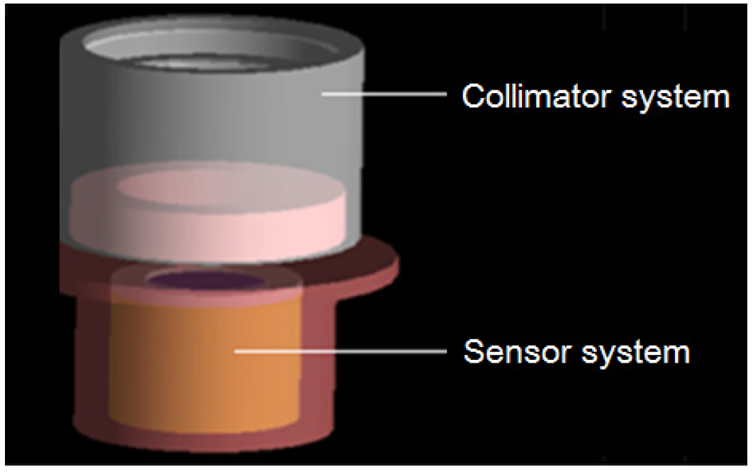
It can be seen from the system scheme that the high-energy particle detector consists of three identical high-energy particle probes and a shared electronics box. The electronics box mainly completes the functions of collecting the output signals of each probe, FPGA data processing, compression, packaging, and communication with the satellite bus interface. Each probe consists of a collimator system, a sensor system, and a front-end electronics system. Figure 4 below is the schematic diagram of the high-energy particle probe structure.

4.2.1. Design of Collimator System

There are two functions of the collimator system. One is to form a suitable detection field of view through the collimation system and to determine the geometric factor of the probe. The other is to provide certain shielding conditions to prevent the interference of particles obliquely incident from the side of the sensor. The collimator system mainly includes three parts: the external structure, the backscatter structure, and the light-blocking layer. The external structure and backscatter structure are used to restrict the geometric factor of the instrument. The collimator system in the high-energy proton probe contains deflection magnets to deflect electrons incident into the collimator.
  • High-energy electron collimation design
The external structure of the collimator is the outermost support and shielding structure of the probe. It was designed as a cup shaped conical structure. To reduce the effect of obliquely incident particles from the side on the measurement results, copper shielding was added outside the probe. The opening diameter of the upper and lower ends of the high-energy electron probe was 24 mm and 5 mm, respectively, and the length was 32 mm, forming a 30° measurement field of view.
In order to reduce the elastic scattering effect of electrons in the material, a backscatter device was added inside the high-energy electron probe with the purpose to prevent the interference of electron scattering in the measurement [29]. Figure 5 below is the schematic diagram of the collimator structure.
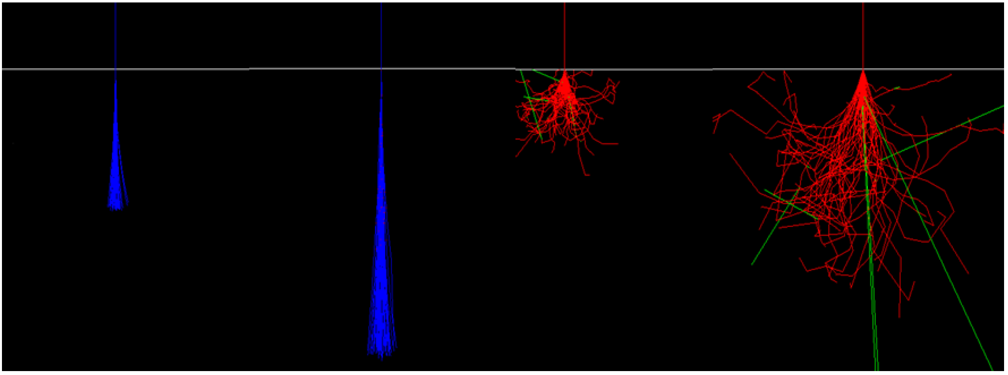
It is known that the scattering of electrons in cutoff is more serious, especially for intermediate-energy electrons of tens to hundreds of keV. Figure 6 shows the scattering comparison between protons and electrons.
From the above figure, the scattering of electrons in cutoff can be observed. When the electrons are incident into the collimator, they may not be absorbed but enter the detector through complex elastic scattering, contributing to measurement errors. Thus, in order to reduce the scattering of electrons inside the collimator, a sawtooth-shaped structure was set inside the collimator. The purpose of this structure is to increase the number of electrons scattering in the collimator, so that the electrons incident in the non-field of view are absorbed by the scattering structure, reducing the interference caused by scattering. Figure 7 shows the collimator with smooth inner walls and using collimation structure.
In addition, the light-blocking layer design was adopted in both the high-energy electron probe and the high-energy proton probe. The purpose of the light-blocking layer was to block sunlight (because the silicon sensor is sensitive to visible light) and micrometeoroids. Its design meets the thermal and mechanical requirements [29], and its thickness has been selected to avoid an increase of the lower measurement limit of the instrument (because the light-blocking layer would reduce the energy of the incident particles).
The materials of the light-blocking layer are mainly elemental films and organic composite materials. For a light-blocking layer above 10 μm, an elemental material can be selected. For a layer with only about a few microns, a composite material is generally selected. The material of the light-blocking layer in the collimator of the high-energy electron probe used a 15 μm aluminum film. The 15 μm aluminum light-blocking layer can block protons below 1 MeV and electrons below 30 keV [29]. The electronic measurement index starts from 200 keV. The energy loss of 200 keV electrons in the light-blocking layer is about 20 keV. Hence, the residual energy is 180 keV, which meets the requirements of the measurable range of electronics.
  • High-energy proton collimation design
When the collimation system in the high-energy proton probe was designed, its external structure was similar to that of the high-energy electron probe. The opening diameter of the upper and lower ends was 31 mm and 10 mm, respectively, and the length was 32 mm, forming a 40° measurement field of view. In contrast with the high-energy electron probe, which used a sawtooth-shaped structure to prevent interference, the high-energy proton probe used a permanent magnet in the collimator to deflect the electrons in order to eliminate the interference and irradiation effects of high-energy electrons on proton detection. For high-energy protons and electrons with the same energy, their energy losses in the silicon semiconductor sensor were the same, and they cannot be identified on the circuit. Therefore, a deflection magnet was used inside the instrument to deflect the high-energy electrons so that they cannot be incident on the silicon sensor, thereby achieving the purpose of excluding interference. Figure 8 shows the external structure of the proton probe.
The basic shape of the deflection magnet in this scheme was the structure of a permanent annular magnet. The central magnetic field strength can reach 4200 Gs, which can effectively remove the influence of electrons < 1 MeV. Additionally, in order to shield the magnetic field of the permanent magnet and reduce the magnetic distance of the instrument, pure iron with high magnetic permeability was used for the shielding around the magnet [30,31].
According to the description of the light-blocking layer in the previous section, a 15 μm aluminum film was also used in the collimator of the high-energy proton probe. The 15 μm aluminum light-blocking layer can block protons below 1 MeV. The proton measurement index starts from 3 MeV. Thus, it fully meets the requirements for the measurable range of electronics.

4.2.2. Design of Sensor System

Semiconductor sensors can receive charged particles incident into the probe. In terms of the linear response range, energy resolution, and spatial applicability, ion-implanted silicon semiconductor sensors are currently the optimal performing semiconductor sensors.
The sensor systems in the high-energy proton and high-energy electron probes of this scheme both adopted the semiconductor detector telescope method [25,26]. The high-energy proton probe used five ion-implanted silicon sensors in combination with a collimator to form a detection field of view with an opening angle of 40°. The high-energy electron probe used six ion-implanted silicon sensors in combination with a collimator to form a detection field of view with an opening angle of 30°. The function of the sensor system is to measure the energy loss of charged particles in the semiconductor detector and convert the energy into electrical signals and provide them to subsequent electronic circuits for analysis. Through the signals of the sensor and by combining with the amplitude analysis method and the appropriate logical working mode, the energy spectrum and flux of the particles can be measured. Ion-implanted semiconductor sensors have excellent energy resolution and are the mainstream sensors currently used.
According to the index design of the instrument, the specific indexes of the high-energy proton and high-energy electron probe sensors are as follows. The thickness of the first sensor is 500μm, and the thickness of the other sensors is 1 mm. The area and diameter of the sensor affect the geometric factor of the instrument, that is, the ability of the instrument to accept particles. Hence, the diameter of the sensor in the high-energy particle probe of this instrument is 12 mm.

4.2.3. Design of Logical Working Modes

Through the combinational design of multi-chip sensors of the HEPD, the response of high-energy protons and electrons with different energies in the sensor can be detected, and the energy of the incident particles can be inverted according to the simulation results.
  • High-energy proton detection logic
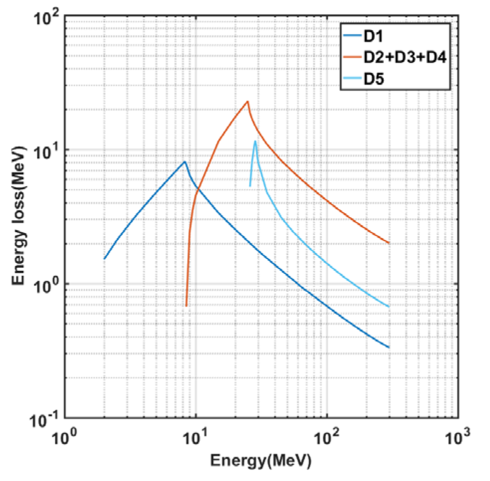
The physical simulation of the high-energy proton detector scheme was completed using Geant4 software [32,33]. Figure 9 shows the energy loss curves of high-energy protons in different sensors obtained via Monte Carlo simulation [34,35]. In Figure 9, D1~D5, respectively, represent different semiconductor detectors from the front to the back of the incident window, and each high-energy proton detector has a total of 5 pieces. According to the simulation calculation results, the energy channel division and logical working modes of the detector can be determined (Table 2).
Each sensor signal was output to the corresponding pre-amplifier circuit separately. Finally, the five channel front-shaped signals were combined into three channel outputs after the main amplifier. According to the above simulation results and logical working principle, the working mode of high-energy proton detection can be determined, as shown in Table 2.
  • High-energy electron detection logic
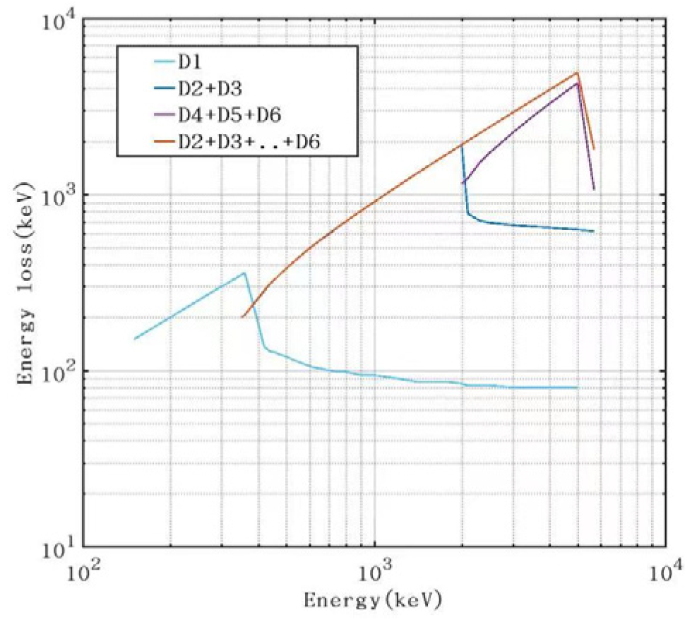
The physical simulation of the high-energy electron detection scheme was completed using Geant4 software [32,33]. Figure 10 shows the energy loss curves of high-energy electrons in different sensors obtained via Monte Carlo simulation [34,35]. In Figure 10, D1~D6, respectively, represent different semiconductor detectors from the front to the back of the incident window, and each high-energy electron detector has a total of 6 pieces. According to the simulation calculation results, the energy channel division and logical working modes of the detector can be determined (Table 3).
A total of 6 sensors were used in the high-energy electron probe sensor system. Each sensor was output to the pre-amplifier circuit independently. Finally, the six channel front-shaped signals were combined into three channel outputs after the main amplifier. The specific combination method was that the first sensor (D1) had a single channel signal A1, the second and third sensors (D2 and D3) were combined into one channel signal A2, and the remaining three sensors (D4, D5, and D6) were combined into one channel signal A3. According to the above simulation results and logical working principle, the working mode of high-energy electron detection can be determined, as shown in Table 3.
Table 3 lists the logical working modes of the high-energy electronic probe, where A1 represents D1, A2 represents D2 + D3, and A3 represents D4 + D5 + D6, that is, the output signals of each detector were added together.

4.2.4. Design of Geometric Factor

When conducting measurements, we assume that the particle flux is isotropic. Next, the instrument’s counting rate has the following relationship to the particle flux in the environment.
S ( cm 2 s 1 sr 1 ) = N counts s G cm 2 sr
where S represents the measured value of the instrument’s flux, N represents the instrument’s count rate, and G represents the instrument’s geometric factor. It can be seen from the above formula that the measurement range of the instrument flux is related to the counting ability per unit time and geometric factor [36].
The geometric factor is very important. It is related to the geometric structure of the detector and the interference of different energies and different types of particles in the counts of each energy range. The geometric factor determines the ability of the instrument to accept space particles and also determines the final count rate state of the instrument. Through the scientific and rational design of the geometric factor of the instrument, it cannot only ensure that the counting of each channel of the instrument will not be saturated, but also avoid the phenomenon where the counting rate is too low and the statistical fluctuation is too large.
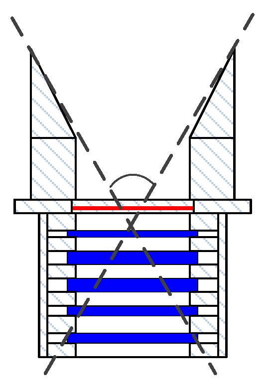
According to the basic structure of the collimator and sensor system in the high-energy particle probe, the detection opening angle of each probe can be determined, as shown in Figure 11.
The detection opening angle of each high-energy proton probe is 40°, and the geometric factor is about 0.30 cm2sr. According to this geometric factor, the counting of each energy range can be evaluated, as shown in Table 4.
The detection opening angle of the high-energy electron probe is 30°, and the geometric factor is about 0.05 cm2sr. According to the measurement results of POES [37,38], the electron flux of >100 keV was about 106 cm2ssr, and the electron flux of >300 keV was about 5 × 105 cm2ssr.
According to the geometric factor of the high-energy electron probe and the maximum electron flux measured by the POES satellite, the counting of each energy range is shown in Table 5. It can be seen that the design of the geometric factor of the high-energy electron probe is reasonable and can meet the electronic requirements of below 105 counts/s.
The minimum particle resolution time of the hardware circuit was 3 uS, and the corresponding maximum counting ability was 3.3 × 10⁵ particles. Considering the random incident effect, the maximum count of general counting is controlled at about 1/5 of the maximum counting ability, which is 6.6 × 10⁴ particles, within the reasonable range of processing.

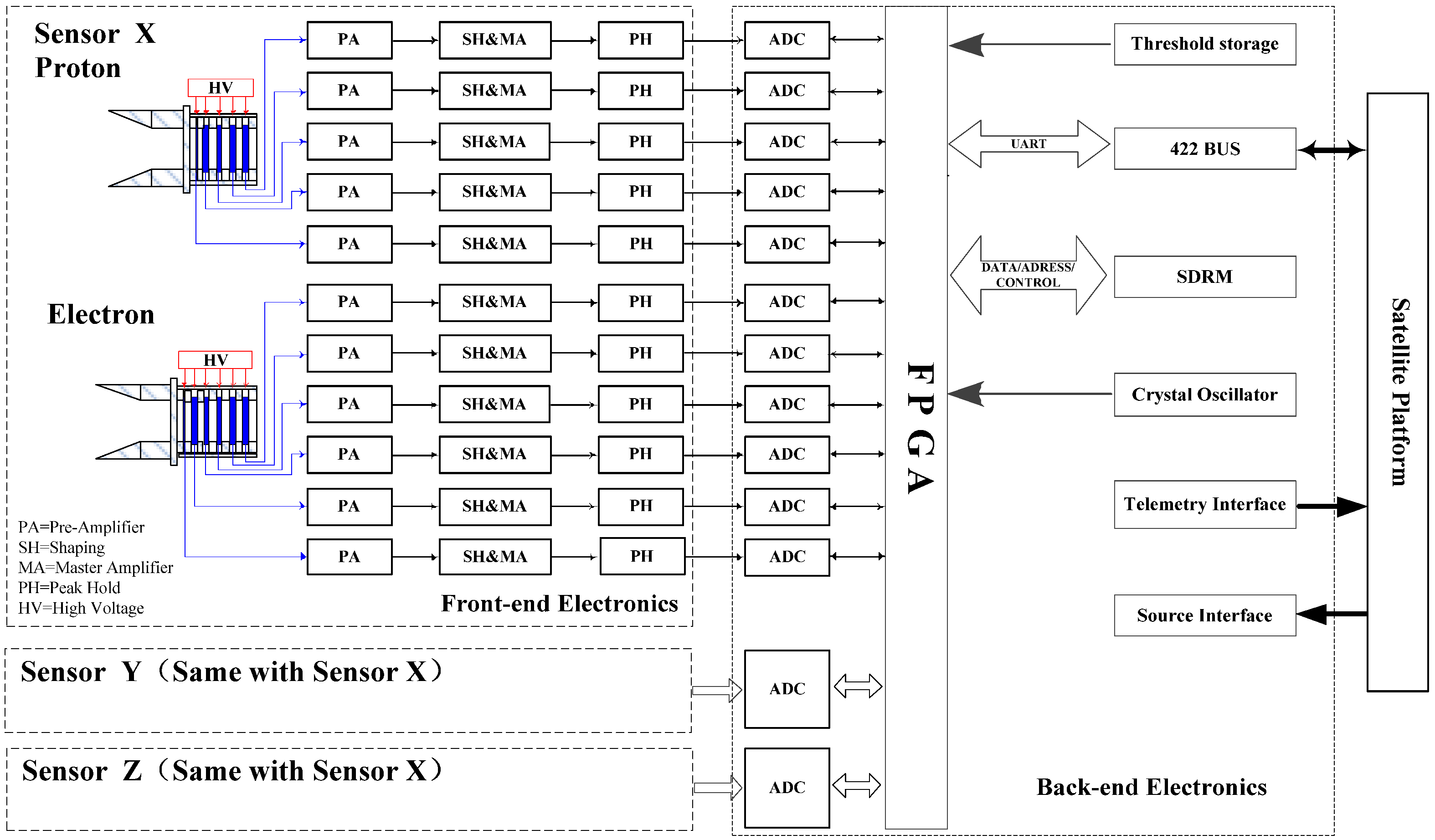
4.2.5. Electronics Design

The electronics design of the HEPD mainly includes the front-end analog electronic circuit of each probe, the back-end digital acquisition and processing circuit, and the satellite bus interface. The front-end signal processing electronics mainly realizes the functions of pre-amplification, pulse shaping, main amplification, and peak holding for the charge pulse signal output by the semiconductor detector in each probe. Subsequently, this signal is sent to the back-end digital circuit part, and the ADCs complete the analog-to-digital conversion of the peak holding signal. The FPGA circuit mainly completes the functions of data processing, compression, storage, and packaging of the signals collected by the ADC, and communicates with the satellite through the interface bus to download the detection data packages. In addition, the instrument electronics also includes power supply modules, noise detection circuits, telemetry interfaces, temperature detection circuits, and sensor bias circuits. The electronics principle of the high-energy particle detector is shown in Figure 12. The sensor and front-end electronics in Figure 12 only show the probe of the −X direction, and the probes of the other two directions have similar electronics.

5. Ground-Based Calibrations

The purpose of the ground-based calibration of the HEPD was to verify and accurately present the detection indexes, including the energy range accuracy, flux accuracy, measuring range, and energy linearity. In this paper, the calibration results of the main indexes such as the energy range and flux accuracy are briefly analyzed and introduced.

5.1. Energy Calibration

5.1.1. Calibration Methods

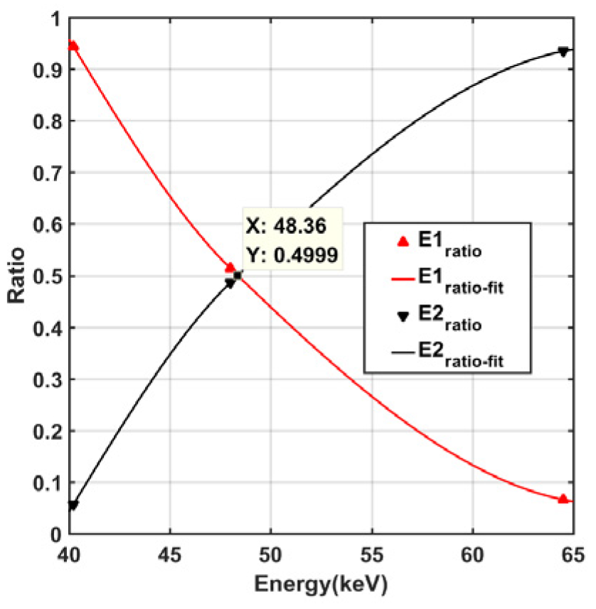
The energy calibration evaluates each energy channel’s measurement error. Additionally, the evaluation result determines the actual energy index and detection accuracy of the instrument. The energy range calibration determines the actual boundary point of the detector energy channel range. The basic principle is that, when a particle with the energy of the boundary point enters the detector, the probability of it falling into the upper and lower energy ranges is equal. It can be expressed by the following formula:
P i , E i = P i + 1 , E i
where i is a certain energy range, Ei is the actual energy boundary, and P is the probability of particles falling into the energy range.
During calibration, a high-energy electron or proton accelerator was used to output a continuously adjustable single-energy particle beam. The whole high-energy particle detector measured the particle beam so that the response of the instrument to particles of different energies can be obtained. According to the actual response situation, the actual energy range that can be recorded by each energy channel can be obtained. Adjusting the particle beam energy and combining with measured data fitting can find the beam energy when the counts of two adjacent channels are equal, that is, the actual measurement boundary of the energy boundary.
As shown in Figure 13, when seeking the actual boundary point of two energy ranges (E5 and E6), the beam energy selects multiple energy points. The two lines represent the probability of protons with different energies falling into the two energy ranges (E5 and E6). When the two lines intersect, it means that the probability of particles falling into the two channels is equal. The incident energy corresponding to the intersection of the two lines is the actual boundary point of the energy ranges (E5 and E6) [39,40].

5.1.2. Calibration Results

The calibration experiments were conducted on the electron and proton accelerator platforms, and the experimental scheme is shown in Figure 14. The instrument was installed in the vacuum target chamber of the accelerator, the sensor center was at the same height as the particle beam, and the incident beam was within the detector opening angle. The output of the high-energy particle detection was transmitted to the data acquisition equipment after the ground test system.
In the calibration experiments, multiple particle beams with specific energy were selected to irradiate the detector. Data analysis was performed on the response of different energy beams, thereby determining the deviation between the actual measurement value and the design value of each energy channel in the instrument.
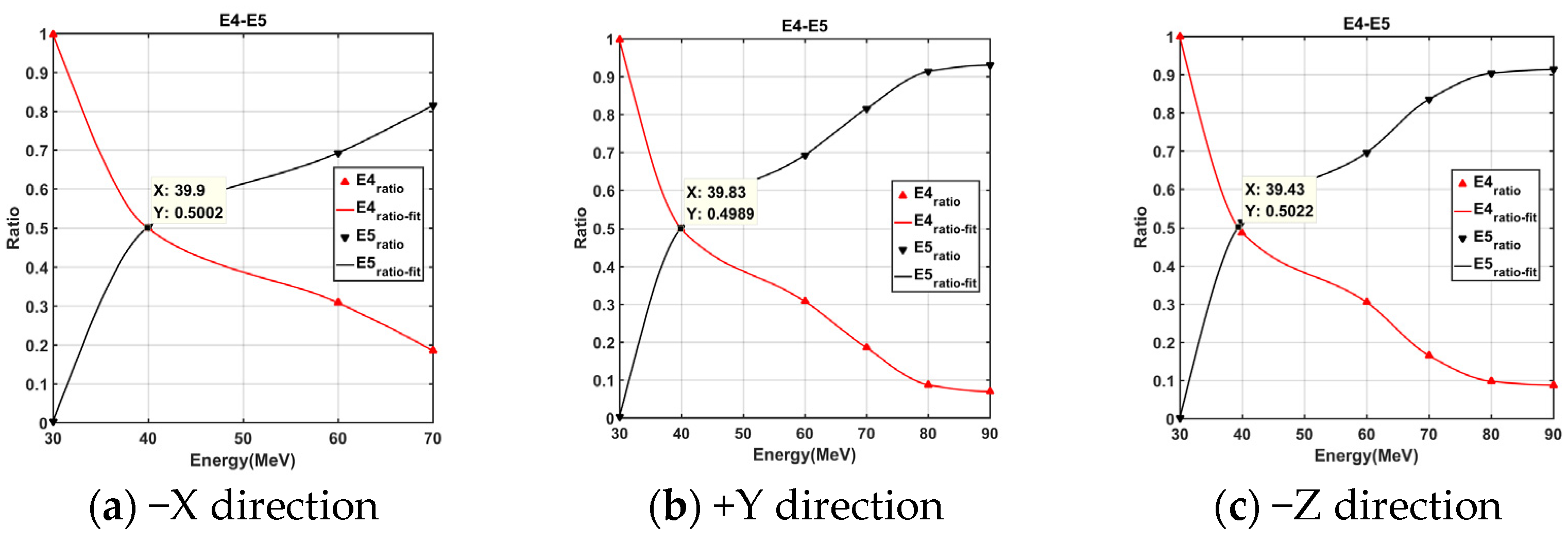
The high-energy proton calibration experiment was conducted in the proton accelerator of the China Institute of Atomic Energy. During the experiment, the energy of the proton beam was adjusted to calibrate the threshold energy (15 MeV, 25 MeV, 40 MeV, and 80 MeV) designed by the instrument. Figure 15 shows the calibration results output by the three probes when the proton energy channel was 40 MeV. Through this analysis [41], it can be seen that the errors of all energy channel divisions in the three directions of high-energy protons were less than 10%, which meets the index requirements of less than 15%.
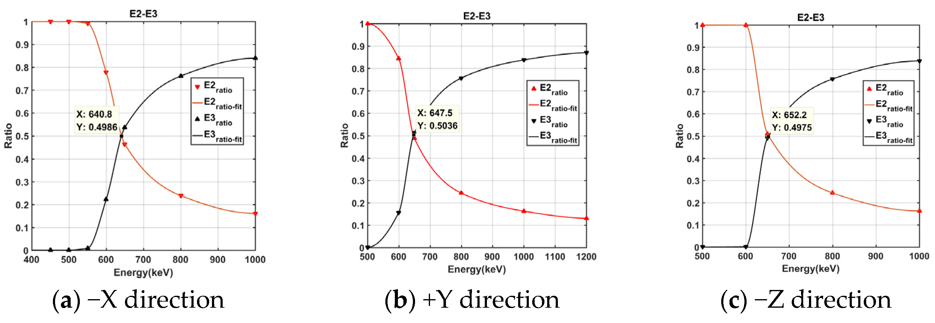
The high-energy electron calibration experiment was performed in the electron accelerator of the National Space Science Center of the Chinese Academy of Sciences. During the experiment, the threshold energy (150 keV, 350 keV, 650 keV, and 1.2 MeV) designed by the instrument was calibrated by adjusting the energy of the electron beam. Figure 16 shows the calibration results output by the three probes when the electronic energy channel was 650 keV. Through analysis, it can be seen that the errors of all electronic energy channel divisions in the three directions of high-energy electrons were less than 5%, which meets the index requirements of less than 15%.
For the high energy range that cannot be covered by the accelerator energy, the test results of the coverage range were used to perform linear extrapolation for calculation [42].

5.2. Flux Accuracy Calibration

5.2.1. Calibration Methods

The purpose of particle flux calibration is to calibrate the actual counting ability of the payload, obtain the corresponding accuracy to the particle flux (that is, with the relationship between the reconnection output and the incident particle counting), determine the detection sensitivity, and finally evaluate the impact of the background noise counting on the detector.
Theoretically, the flux error can be directly calibrated by a particle source with a known flux to the detector. However, in fact, the particle flux is not stable regardless of the accelerator or radioactive source. Therefore, there is no accurate and reliable method for direct calibration of flux [25]. In order to calibrate the particle flux error, an indirect method of decomposing the flux error into various contributing errors, measuring them separately, and then superimposing them into the total flux error is adopted.
The direct detection quantity of the detector is the counting N (counts/s). In order to facilitate the comparison of the data, the data need to be normalized. The counting is divided by the geometric factor G of the instrument, and then the flux of the detector is obtained as
M ( cm 2 s 1 sr 1 ) = N counts s G cm 2 sr
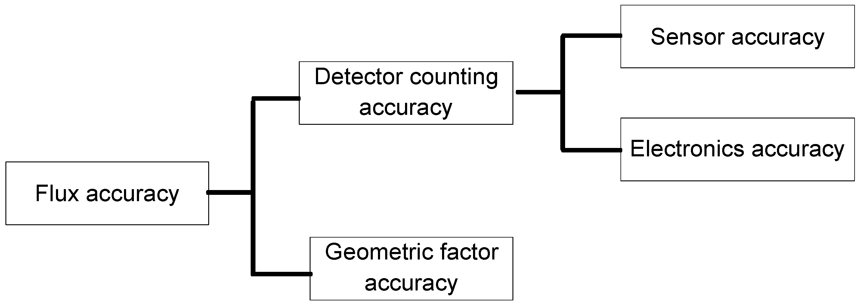
Therefore, there are two factors that affect the flux calibration accuracy, namely, the instrument counting accuracy and the geometric factor accuracy. The counting is the initial output data of the payload, and it is directly related to its sensor and electronics. Hence, the error of the counting includes the particle response error of the sensor and the response error of the electronics, as shown in Figure 17.
Assume that the relative accuracy of the detector flux M is σ M , the relative accuracy of the counting is σ N , and the relative accuracy of the geometric factor is σ G . According to the formula of error propagation,
σ y 2 = i ( y x i ) 2 σ x i 2
The relative accuracy of the flux is obtained as,
σ M 2 = M N 2 σ N 2 + M G 2 σ G 2 = 1 G 2 σ N 2 + N 2 G 4 σ G 2
The sensor counting error calibration was tested separately using the silicon semiconductor detectors of the same batch. The sensor was placed in a test box, and the sensor was irradiated with a 207Bi radioactive source. The total count recorded by the sensor per unit time was counted by the dedicated multi-channel system for sensor measurement.
The above steps were repeated continuously to obtain a series of counting rates n i . Finally, the counting response error of the sensors of the batch was obtained by calculating the standard deviation method. The electronic counting error calibration was mainly obtained by writing software and using the random function generator in the program to simulate the time distribution of the space particle injecting into the sensor. If the signal collection time of the instrument is t, when the time difference between two particles incident is less than t, only one of the large signals is recorded. The counts that were “eaten” due to signal superposition and the actual counts of the detectors were recorded to obtain the electronic counting errors of the detector. The use of the particle incidence of different fluxes in the calibration yielded the corresponding relation between the number of incident particles and the detector output counts.
The geometric factor is an important characteristic parameter of the detector. It is a necessary parameter for data normalization and data comparison. The method of obtaining the geometric factor error is to simulate the geometric factor value G i of each energy channel with the same input parameters and then obtain the geometric factor error σ G according to the error propagation function.

5.2.2. Calibration Results

According to the above calibration methods, the calibration results of different items can be obtained. The final calculation results of the flux accuracy errors of the high-energy particle detector are shown in Table 6.

5.3. Sensitivity Calibration

Sensitivity refers to the minimum space environment change that can cause a one-count change in the payload. The main determinant is the geometric factor G. Next, the lowest flux change that the detector can respond to is 1/G, and the detector sensitivity is,
1 / G N × 100 %
The geometric factor of the high-energy proton detector G = 0.30 cm2sr. According to the aforementioned detection sensitivity test method, the flux increase that causes a count change in the sensor is ∆N = 3.3 cm−2sr−1. When the flux is >66 cm−2s−1sr−1, the sensitivity of the detector is better than 5%. Similarly, the geometric factor of the high-energy electron detector G = 0.046 cm2sr. Therefore, the flux increase that causes a count change in the sensor is ∆N = 21.7 cm−2sr−1. When the flux is >434 cm−2s−1sr−1, the sensitivity of the detector is better than 5%.

6. Conclusions

The HEPD described in this study performed energy spectrum and flux observations of high-energy protons and electrons in the LEO orbit. The performance indexes of the instrument were verified by ground-based calibration experiments, and the results represent that all the HEPDs’ measured values meet the requirements for technical indexes, such as the detection energy range, energy span accuracy, flux accuracy and sensitivity. The HEPD obtained a large amount of on-orbit space environment detection data, which have been applied to satellite operation and on-orbit management analysis, effectively promoting the development of space environment and space weather research in China.

Author Contributions

Conceptualization, G.S.; methodology, G.S.; software, P.Z.; validation, P.Z.; formal analysis, S.Z.; investigation, S.Z.; resources, S.Z.; data curation, X.Z. (Xianguo, Zhang); writing—original draft preparation G.S.; writing—review and editing, G.S.; supervision, Y.Y. and Y.S.; project administration, J.W.; funding acquisition, X.Z. (Xiaoxin, Zhang), C.H. and J.L. All authors have read and agreed to the published version of the manuscript.

Funding

This work was supported by the National Natural Science Foundation of China (41931073) and the National Key R&D Program of China (2021YFA0718600).

Data Availability Statement

No new data were created or analyzed in this study. Data sharing is not applicable to this article.

Acknowledgments

This work was supported by the Key Laboratory of Space Weather, National Satellite Meteorological Center, China Meteorological Administration. The authors thank the management and technical support of the Shanghai Institute of Satellites Engineering for their efforts to create the excellent satellite operation conditions available.

Conflicts of Interest

The authors declare no conflict of interest.

References

  1. Xian, D. FengYun NO. 3—Li Ming Satellite. Satell. Appl. 2022, 1, 70. [Google Scholar]
  2. He, X.Y.; Cai, X.F.; Zhu, Y.P.; Zhang, L. China’s Fengyun polar orbit meteorological satellite and its application progress. Adv. Meteorol. Sci. Technol. 2021, 11, 34–39. [Google Scholar]
  3. China successfully launched Fengyun NO. 3 E satellite. Infrared 2021, 42, 54. Available online: http://www.xinhuanet.com/tech/2021-07/05/c_1127622185.htm (accessed on 23 December 2022).
  4. Gao, H.; Tang, S.H.; Han, X.Z. China’s Fengyun (FY) meteorological satellites, development and applications. Sci. Technol. Rev. 2021, 39, 9–22. [Google Scholar]
  5. Zhang, P.; Xu, Z.; Guan, M.; Xie, L.; Xian, D.; Liu, C. Progress of Fengyun Meteorological Satellites Since 2020. Chin. J. Space Sci. 2022, 42, 724–732. [Google Scholar] [CrossRef]
  6. Wang, C.Q.; Zhang, X.; Zhang, L.G.; Zhang, R.Y.; Jin, L.Q.; Sun, Y.Q.; Jing, T.; Zhang, K.Y.; Zhang, H.X.; Chang, Z. Space Radiation Environment Observations and Applications Based on GEO Satellites. Aerosp. Shanghai 2017, 34, 85–95. [Google Scholar]
  7. Feng, Y.J.; Hua, G.X.; Liu, S.F. Summary of research on radiation resistance of aerospace electronics. J. Astronaut. 2007, 05, 1071–1080. [Google Scholar]
  8. Zhu, G.W.; Li, B.Q.; Wang, S.J.; Liang, J.B.; Zhang, W.; Huang, H.J.; Shen, S.Z.; Zhai, Y.Y.; Sun, Y.Q.; Ye, Z.H. Analysis of influence of solar proton events on the space radiation environment of solar synchronous orbit. Chin. J. Space Sci. 2002, 22, 58–64. [Google Scholar]
  9. Xue, Y.X.; Yang, S.S.; Ba, D.D.; An, H.; Liu, Q.; Shi, H.; Cao, Z. Analysis of spacecraft faults or anomalies by space radiation environment. Vacuun Low Temp. 2012, 18, 63–70. [Google Scholar]
  10. di Stefano, I.; Cappuccio, P.; Iess, L. The BepiColombo solar conjunction experiments revisited. Class. Quantum Gravity 2021, 38, 055002. [Google Scholar] [CrossRef]
  11. Turyshev, S.G.; Toth, V.T. The Pioneer Anomaly. Living Rev. Relativ. 2010, 13, 4. [Google Scholar] [CrossRef]
  12. Jordan, J.F.; Madrid, G.A.; Pease, G.E. Effects of Major Errors Sources on Planetary Spacecraft Navigation Accuracies. J. Spacecr. Rocket. 1972, 9, 196–204. [Google Scholar] [CrossRef]
  13. Asmar, S.W.; Armstrong, J.W.; Iess, L.; Tortora, P. Spacecraft Doppler tracking: Noise budget and accuracy achievable in precision radio science observations. Radio Sci. 2005, 40, 1–9. [Google Scholar] [CrossRef]
  14. Xue, B.S.; Ye, Z.H. Study on the long-term prediction method of solar proton events. Manned Spacefl. 2007, 4, 47–53. [Google Scholar]
  15. Xue, B.S.; Ye, Z.H. Forecast of the enhancement of relativistic electron at the geo-synchronous orbit. Chin. J. Space Sci. 2004, 24, 283–288. [Google Scholar]
  16. Wang, S. Current situation and trend of solar-terrestrial system research. J. Geophys. 1996, 4, 449–450. [Google Scholar]
  17. Yang, X.C.; Wang, S.J.; Liang, J.B.; Shen, G.H. Electron orientation detection design on sun-synchronous orbit. J. Astronaut. 2012, 33, 281–284. [Google Scholar]
  18. Vincenzo, V.; Francesco, P.; Alessandro, S. The High-Energy Particle Detector on board of the CSES mission. EPJ Web Conf. 2017, 136, 01007. [Google Scholar]
  19. Jo, G.B.; Sohn, J.; Choi, C.R.; Yi, Y.; Min, K.W.; Kang, S.B.; Na, G.W.; Shin, G.H. Development of High Energy Particle Detector for the Study of Space Radiation Storm. J. Astron. Space Sci. 2014, 31, 277–283. [Google Scholar] [CrossRef]
  20. Le, G.M.; Ye, Z.H. The Study of Space Distribution Configuration of the Radbelt Protons with High Energy. Chin. J. Space Sci. 2003, 23, 278–285. [Google Scholar]
  21. Buhler, P.; Desorgher, L.; Zehnder, A.; Daly, E.; Adams, L. Observations of the low earth orbit radiation environment from MIR. Radiat. Meas. 1996, 26, 917–921. [Google Scholar] [CrossRef] [PubMed]
  22. Lazutin, L.L.; Kuznetsov, S.N.; Podorol’skii, A.N. Dynamics of the radiation belt formed by solar protons during magnetic storms. Geomagn. Aeron. 2007, 47, 175–184. [Google Scholar] [CrossRef]
  23. Chen, G.F.; Ye, Z.H.; Zhu, G.W.; Shen, S.Z.; Liang, J.B.; Huang, H.J. Variation of proton in inner radiation belt during solar proton events. Chin. J. Geophys. 1993, 04, 428–433. [Google Scholar]
  24. Wissing, J.M.; Bornebusch, J.P.; Kallenrode, M.-B. Variation of energetic particle precipitation with local magnetic time. Adv. Space Res. 2007, 41, 1274–1278. [Google Scholar] [CrossRef]
  25. Ye, Z.H. Space Particle Radiation Detection Technology; Beijing Science Press: Beijing, China, 1986; pp. 77–78. [Google Scholar]
  26. Jiao, W.X. Space Exploration; Peking University Press: Beijing, China, 2002. [Google Scholar]
  27. Wimmer Schweingruber, R.F.; Janitzek, N.P.; Pacheco, D.; Cernuda, I.; Lara, F.E.; Gómez-Herrero, R.; Mason, G.M.; Allen, R.C.; Xu, Z.G.; Carcaboso, F.; et al. First year of energetic particle measurements in the inner heliosphere with Solar Orbiter’s Energetic Particle Detector. Astron. Astrophys. 2021, 656, A22. [Google Scholar] [CrossRef]
  28. Rodriguez Pacheco, J.; Wimmer Schweingruber, R.F.; Mason, G.M.; Ho, G.C.; Sánchez-Prieto, S.; Prieto, M.; Martín, C.; Seifert, H.; Andrews, G.B.; Kulkarni, S.R.; et al. The Energetic Particle Detector. Energetic particle instrument suite for the Solar Orbiter mission. Astron. Astrophys. 2019, 642, A7. [Google Scholar] [CrossRef]
  29. Hou, D.H.; Zhang, S.Y.; Zhang, X.X.; Zong, W. Design and research of collimator for space high-energy electron detector. J. Vac. Sci. Technol. 2020, 40, 965–970. [Google Scholar]
  30. Zhang, S.Y.; Wang, S.J. Design and research of deflection magnet in spaceborne particle detector. Chin. J. Geophys. 2007, 03, 684–690. [Google Scholar]
  31. Zhang, S.Y.; Zhang, X.G.; Wang, C.Q.; Shen, G.H.; Jing, T.; Zhang, B.Q.; Sun, Y.Q.; Zhu, G.W.; Liang, J.B.; Zhang, X.X.; et al. Calculation of geometric factors of space high-energy proton detector of FY-3 satellite. Sci. Sin. 2014, 44, 2479–2486. [Google Scholar]
  32. Douglass, M.; Bezak, E. Physical Modelling of Proton and Heavy Ion Radiation using Geant4. EPJ Web Conf. 2012, 35, 04001. [Google Scholar] [CrossRef]
  33. Khoo, L.Y.; Li, X.; Selesnick, R.S.; Schiller, Q.; Zhang, K.; Zhao, H.; Hogan, B.; Cantilina, J.T.; Sims, A.; Bauch, E.; et al. On the Challenges of Measuring Energetic Particles in the Inner Belt: A Geant4 Simulation of an Energetic Particle Detector Instrument, REPTile-2. J. Geophys. Res. Space Phys. 2022, 127, e2021JA030249. [Google Scholar] [CrossRef]
  34. Beretta, M.; Biassoni, M.; Gironi, L.; Maino, M.; Nastasi, M.; Pagnanini, L.; Pozzi, S. Monte Carlo simulation of particle detector data stream. Eur. Phys. J. Plus 2021, 136, 89. [Google Scholar] [CrossRef]
  35. Yando, K.; Millan, R.M.; Green, J.C.; Evans, D.S. A Monte Carlo simulation of the NOAA POES medium energy proton and electron detector instrument. J. Geophys. Res. Space Phys. 2011, 116, 10231. [Google Scholar] [CrossRef]
  36. Zhang, S.Y.; Zhang, X.G.; Wang, C.Q.; Shen, G.; Jin, T.; Zhang, B.; Sun, Y.; Zhu, G.; Liang, J.; Zhang, X.; et al. The geometric factor of high energy protons detector on FY-3 satellite. Sci. China Earth Sci. 2014, 57, 2558–2566. [Google Scholar] [CrossRef]
  37. Babu, E.M.; Tyssøy, H.N.; SmithJohnsen, C.; Maliniemi, V.; Salice, J.A.; Millan, R.M.; Richardson, I.G. Determining Latitudinal Extent of Energetic Electron Precipitation Using MEPED On-Board NOAA/POES. J. Geophys. Res. Space Phys. 2022, 127, e2022JA030489. [Google Scholar] [CrossRef]
  38. Sandanger, M.I.; Glesnes Ødegaard, L.K.; Tyssøy, H.N.; Stadsnes, J.; Søraas, F.; Oksavik, K.; Aarsnes, K. In-flight calibration of NOAA POES proton detectors—Derivation of the MEPED correction factors. J. Geophys. Res. Space Phys. 2015, 120, 9578–9593. [Google Scholar] [CrossRef]
  39. Belhaj, M.; Dadouch, S. A simple method for energy calibration of keV incident electron beam using a contactless electrostatic voltmeter probe. Rev. Sci. Instrum. 2021, 92, 083301. [Google Scholar] [CrossRef]
  40. Maier, D.; Limousin, O. Energy calibration via correlation. Nucl. Inst. Methods Phys. Res. A 2016, 812, 43–49. [Google Scholar] [CrossRef] [Green Version]
  41. Zhang, C.Y.; Liang, X.H.; Xu, Y.B.; Peng, W.; He, J.; Guo, D.; Gong, K.; Liu, Y.; An, Z.; Zhang, D.; et al. Result of proton beam energy calibration of GECAM satellite charged particle detector. Radiat. Detect. Technol. Methods 2021. prepublish. [Google Scholar] [CrossRef]
  42. He, Z.Y.; Steckmeyer, J.C.; Kerambrun, A. Time and energy calibration of silicon telescope with secondary beam. Nucl. Tech. 1993, 16, 705–709. [Google Scholar]
Figure 1. Diagram of high-energy particle detector system composition.
Aerospace 10 00173 g001
Figure 2. Photos of the high-energy particle detector ((Left panel): −X probe; (central panel): +Y/Z probe; (right panel): electronic box).
Aerospace 10 00173 g002
Figure 3. Schematic diagram of telescope system in the high-energy particle detector.
Aerospace 10 00173 g003
Figure 4. Schematic diagram of the high-energy particle probe structure.
Aerospace 10 00173 g004
Figure 5. Backscatter structure.
Aerospace 10 00173 g005
Figure 6. Scattering comparison between protons and electrons (Blue: protons; Red: electrons; Green: Protons path).
Aerospace 10 00173 g006
Figure 7. Collimator with smooth inner walls and collimator using collimation structures.
Aerospace 10 00173 g007
Figure 8. External structure of the proton probe.
Aerospace 10 00173 g008
Figure 9. Energy loss curves of protons in semiconductor sensors.
Aerospace 10 00173 g009
Figure 10. Energy loss curves of electrons in semiconductor sensors.
Aerospace 10 00173 g010
Figure 11. Schematic diagram of detection opening angle structure in the high-energy particle detector.
Aerospace 10 00173 g011
Figure 12. Schematic diagram of the HEPD’s electronics principle.
Aerospace 10 00173 g012
Figure 13. The principle of energy range calibration.
Aerospace 10 00173 g013
Figure 14. Experimental scheme of energy channel calibration.
Aerospace 10 00173 g014
Figure 15. Calibration results of proton energy channel in three directions (40 MeV).
Aerospace 10 00173 g015
Figure 16. Calibration results of the electron energy channel in three directions (650 keV).
Aerospace 10 00173 g016
Figure 17. Influencing factors of flux calibration accuracy.
Aerospace 10 00173 g017
Table 1. Main technical indexes of the HEPD on the FY-3E satellite.
ItemEnergy RangeDetection FieldSensitivity
High-energy protons3~300 MeV40°5% (ΔN/N)
High-energy electrons0.15–5.7 MeV30°5% (ΔN/N)
Table 2. Logical working modes of high-energy proton probe.
Energy ChannelEnergy Range Logical Working Modes
P13–5 MeV D 1 2.64 · D 1 4.76 ¯ · ( D 2 + D 3 + D 4 ) 2.0 ¯ · D 5 ¯ 0.7
P25–10 MeV D 1 4.76 · D 1 8.30 ¯ · ( D 2 + D 3 + D 4 ) 4.51 ¯ · D 5 ¯ 0.7
P310–26 MeV D 1 2.00 · D 2 + D 3 + D 4   4.51 · ( D 2 + D 3 + D 4 ) 25.0 ¯ · D 5 ¯ 0.7
P426–40 MeV D 2 + D 3 + D 4   9.76 · ( D 2 + D 3 + D 4 ) 25.0 ¯ · D 5 0.7
P540–100 MeV D 2 + D 3 + D 4   4.33 · ( D 2 + D 3 + D 4 ) 9.77 ¯ · D 5 0.7
P6100–300 MeV D 2 + D 3 + D 4   2.08 · ( D 2 + D 3 + D 4 ) 4.33 ¯ · D 5 0.7
Table 3. Logical working modes of high-energy electron probe.
Energy ChannelEnergy RangeLogical Working Modes
E10.15–0.35 MeV A 1 0.14 · A 1 ¯ 0.35 · A 2 ¯ 0.1 · A 3 ¯ 0.1
E20.35–0.65 MeV A 1 ¯ 0.65 · A 2 0.1 · A 2 ¯ 0.56 · A 3 ¯ 0.1
E30.65–1.20 MeV A 1 ¯ 1.0 · A 2 0.56 · A 2 ¯ 1.14 · A 3 ¯ 0.1
E41.2–2.0 MeV A 1 ¯ 1.0 · A 2 + A 3 1.14 · A 2 + A 3 ¯ 1.94
E52.0–5.7 MeV A 1 ¯ 1.0 · A 2 + A 3 1.94 · A 2 + A 3 ¯ 3.0
E63.0–5.7 MeV A 1 ¯ 1.0 · A 2 + A 3 3.0 · A 2 + A 3 ¯ 5.0
Table 4. Estimation of maximum count rate for high-energy proton probes.
Energy Range
(MeV)
Flux
(cm2ssr)
FY-3E Satellite Maximum (Counts/s)
3–51 × 101–3 × 1031 × 103
5–101 × 101–2 × 1036 × 102
10–261 × 101–1 × 1033 × 102
26–401 × 101–6 × 1022 × 101
40–1001 × 101–1 × 1033 × 102
100–3001 × 101–1 × 1033 × 102
Table 5. Estimation of maximum count rate for high-energy electron probes.
Energy Range
(MeV)
Flux
(cm2ssr)
FY-3E Satellite Maximum (Counts/s)
0.15–0.355 × 10⁵–1064 × 104
0.35–0.651 × 10³–4 × 1052 × 104
0.65–1.201 × 10³–5 × 1042 × 102
1.20–2.01 × 10³–1 × 1045 × 101
2.0–5.71 × 10³–1 × 1045 × 101
Table 6. Calibration results of particle flux.
Electronic Counting ErrorSensor Counting ErrorGeometric Factor ErrorFlux Error
Error0.95%4.8%3%8.75%
Disclaimer/Publisher’s Note: The statements, opinions and data contained in all publications are solely those of the individual author(s) and contributor(s) and not of MDPI and/or the editor(s). MDPI and/or the editor(s) disclaim responsibility for any injury to people or property resulting from any ideas, methods, instructions or products referred to in the content.