Article

Predefined-Time Control of a Spacecraft Attitude with Thrust Booms

1
Department of Control Science and Engineering, Harbin Institute of Technology, Harbin 150001, China
2
Shanghai Academy of Spaceflight Technology, Beijing R&D Center, Beijing 100081, China
*
Author to whom correspondence should be addressed.
Aerospace 2023, 10(2), 94; https://doi.org/10.3390/aerospace10020094
Submission received: 16 November 2022 / Revised: 1 January 2023 / Accepted: 10 January 2023 / Published: 17 January 2023
(This article belongs to the Section Astronautics & Space Science)

Abstract

:
A predefined-time attitude controller for electric spacecraft and its thrust booms is investigated by combining a second-order sliding mode control with predefined-time disturbance observer. First, an Eulerian–Lagrangian attitude dynamics model of the electric spacecraft with thrust booms is constructed; meanwhile, the coupling between the spacecraft platform and thrust boom is treated as the disturbance when designing the controller. Next, a predefined-time convergent second-order sliding surface and reaching law are designed to ensure the predefined-time fast convergence. The second-order sliding surface can avoid the chattering problem of controller and improve the anti-disturbance capability of the spacecraft. Furthermore, a novel predefined-time disturbance observer is developed to handle the disturbances, ensuring that the tracking error of the system converges to the equilibrium. At last, the simulation is performed to verify the feasibility and advantages of the proposed algorithm.

1. Introduction

The most important topic at this time is how to achieve the goal of reducing fuel consumption in the operation of spacecrafts [1]. During deep space exploration, it is inevitable to perform the orbital transfer of spacecrafts, and if chemical thrusters are chosen, a large amount of fuel needs to be carried, thus reducing the efficiency of using the spacecraft [2]. Therefore, the electric propulsion spacecraft, which is the next generation of spacecraft using electric power as the source of thrust, is an important guarantee for future space missions. Compared to the conventional chemical thruster, the electric thruster has a high specific impulse and low cost, which allows spacecrafts to carry more payloads and reduce launch costs [2,3]. The chemical thruster is capable of producing hundreds of Newtons for orbital control [4] and completing the required orbital control after only a few impulse maneuvers. In comparison, the most sophisticated electric propulsion systems generate a maximum thrust of hundreds of milli-newtons [5]. Therefore, the use of electric propulsion requires continuous operation over an extended period of time. Completion of the spacecraft orbit control target requires the engine to be in a fixed position for a significant amount of time. If the electric propulsion engine is attached to the spacecraft platform, the attitude of the spacecraft will be aligned with the engine attitude, which significantly reduces the flexibility of the spacecraft. In order to decouple the spacecraft platform from the electric propulsion engine, the electric propulsion engine is attached to the thrust boom, so the observation mission can also be completed during the orbit transition period [6]. However, electric propulsion spacecraft research is currently focused on the optimization of the electric propulsion boom joints and control of the spacecraft body [7,8,9]. It is worth paying attention to how to achieve a fast thrust boom response and maintain spacecraft platform stability with high accuracy after obtaining the required joint angle.
It is well known that spacecrafts are usually subject to various external disturbances in space, and disturbance observers are one of the most common methods to cope with this problem. B Li et al. proposed a continuous finite-time state observer that can observe the attitude angular velocity and the total disturbance [10]. I Nagesha et al. constructed a novel sliding mode observer by designing a multivariable super-twisting structure, which can detect and isolate the faults of the spacecraft [11]. A fixed-time observer is proposed by Z Liu et al. for estimating external disturbances, uncertainties of inertial parameters and actuator uncertainties, which can guarantee the fixed-time convergence of the estimation error to zero [12]. In addition to this traditional observer, considering the powerful estimation capability of neural networks, some methods using neural networks for disturbance estimation have emerged at this stage. For example, C Zhang et al. used neural networks to approximate disturbances with high accuracy and finally achieve a high accuracy stabilization of spacecraft attitude [13]. Zhang et al. proposed a novel fuzzy PID controller optimization method based on artificial electric field algorithm (AEFA) and applied it to the attitude control of spacecraft. The implementation demonstrates that the method can effectively reduce the steady-state error and improve the immunity of the system [14]. Q Hu et al. proposed an iterative learning observer to ensure that the estimation error of moment deviation enters a very small residual set [15]. However, the time of stabilization in the above observer cannot be directly reflected in the observer parameters.
The controller based on the sliding mode control theory usually has a strong robustness, so it is also used in spacecraft attitude control. To further improve the control effect of the sliding mode controller, many scholars have combined it with other control theory to achieve the corresponding control purpose. Y Miao et al. combined the sliding mode control and adaptive control for controller design, where the upper bound of disturbance was estimated by the adaptive law [16]. Xia et al. proposed a new adaptive non-singular terminal sliding mode (ANTSM) control method based on an improved radial basis function neural network (RBFNN) for achieving the trajectory tracking control of a spatial robotic system (SRS) in the presence of aggregate uncertainty [17]. J Fu et al. combined a neural network and sliding mode controller to achieve the fast convergence of spacecraft attitude and angular velocity, and the optimal energy consumption of the actuator is achieved by continuously correcting the parameters through neural networks [18]. Pukdeboon et al. designed an optimal sliding mode control law by combining the optimal control with the integral sliding mode to achieve the spacecraft attitude control with external disturbances and inertia uncertainty [19]. In addition, to reduce the chattering problem of the controller and improve the control accuracy, the higher-order sliding mode control has been widely studied. In order to cope with the environmental disturbances as well as the parameter uncertainties, P Mohan et al. proposed an integral second order sliding mode that can achieve attitude stabilization of a rigid spacecraft [20]. However, these control methods do not take into account the settling-time of the spacecraft system.
In practical engineering missions, the spacecraft attitude is usually required to converge to the specified angle within a certain time, so it is very important to stabilize the spacecraft attitude to the desired attitude quickly. To solve this problem, new control algorithms such as the finite-time control have been proposed in turn. Finite-time controllers are mainly implemented by two methods, including adding power integrator technique and terminal sliding mode, and they are widely used in practical systems [10,21,22,23]. These studies are demonstrated that finite-time control methods have the advantages of faster convergence, higher steady-state tracking accuracy, and better suppression of disturbances. Geng et al. devised a finite-time optimal control law to ensure that the control target metted within a specified time and ensured that the energy consumption is optimal [22]. Hua et al. designed a multi-stage saturated coherent cooperative controller for attitude orbit coupling in the presence of communication constraints [24]. Gao et al. proposed a finite-time predetermined performance function to achieve the finite-time control of the system through error variation as well as barrier Lyapunov function [23]. However, since the upper bound of the convergence time of the finite-time controller is related to the initial state of the system, the convergence time is not determined in advance. Further, a method called the fixed-time control was proposed [25,26], which solves the problem that the convergence time is affected by the initial conditions. Du et al. designed a fixed-time convergence controller for a rigid spacecraft based on a modified backstepping method, where the convergence time is independent of the initial value of the system [25]. Zhou et al. studied the fixed-time control in the presence of constraints, using performance function and output error conversion techniques to convert tracking error dynamics with unequal performance constraints to equivalent unconstrained error dynamics, and introduced the fixed-time sliding surface into the controller design, while solving the saturation problem [26]. Although the finite-time or fixed-time control methods can ensure a fast attitude stabilization, the upper bound of stabilization time requires complex calculation and cannot be explicitly included in the controller parameters.
The above methods have achieved good results in spacecraft attitude control; there are still many problems to be solved for the electric propulsion spacecraft with the thrust boom. In this paper, the spacecraft platform attitude stabilization during its electric thrust booms tracking the desired signal is studied. By using predefined-time control theory, a second-order sliding mode controller is proposed, which ensures the spacecraft platform attitude stabilization and ensures that joint angles are able to track on the desired signal within a predefined time. It is noteworthy that the settling time is contained in the controller as a control parameter, which reduces the complexity of the design process. Considering external disturbance, a predefined-time disturbance observer is developed to compensate the sum of disturbances to address their impact on the control accuracy. In summary, its advantages can be summarized as: (1) This paper investigates the practical problems of thrust booms and platform attitude control of an electric spacecraft. (2) A predefined-time disturbance observer without a prior information of the disturbance is developed to estimate the various disturbance. (3) A novel predefined-time second-order sliding mode controller is developed to achieve the rapid attitude response of spacecraft platform and thrust booms. (4) The settling times of the estimation error and tracking error are explicitly included in the observer and controller, respectively.
The article is organized as follows. Section 2 gives a mathematical model and problem formulation. Section 3 and Section 4 focuses on the controller design and its stability analysis. In Section 5, the control algorithm is applied to an actual system and shows the simulation results, which can verify the effectiveness of the algorithm. Finally, the conclusion is presented in Section 6.

2. Mathematical Model and Problem Formulation

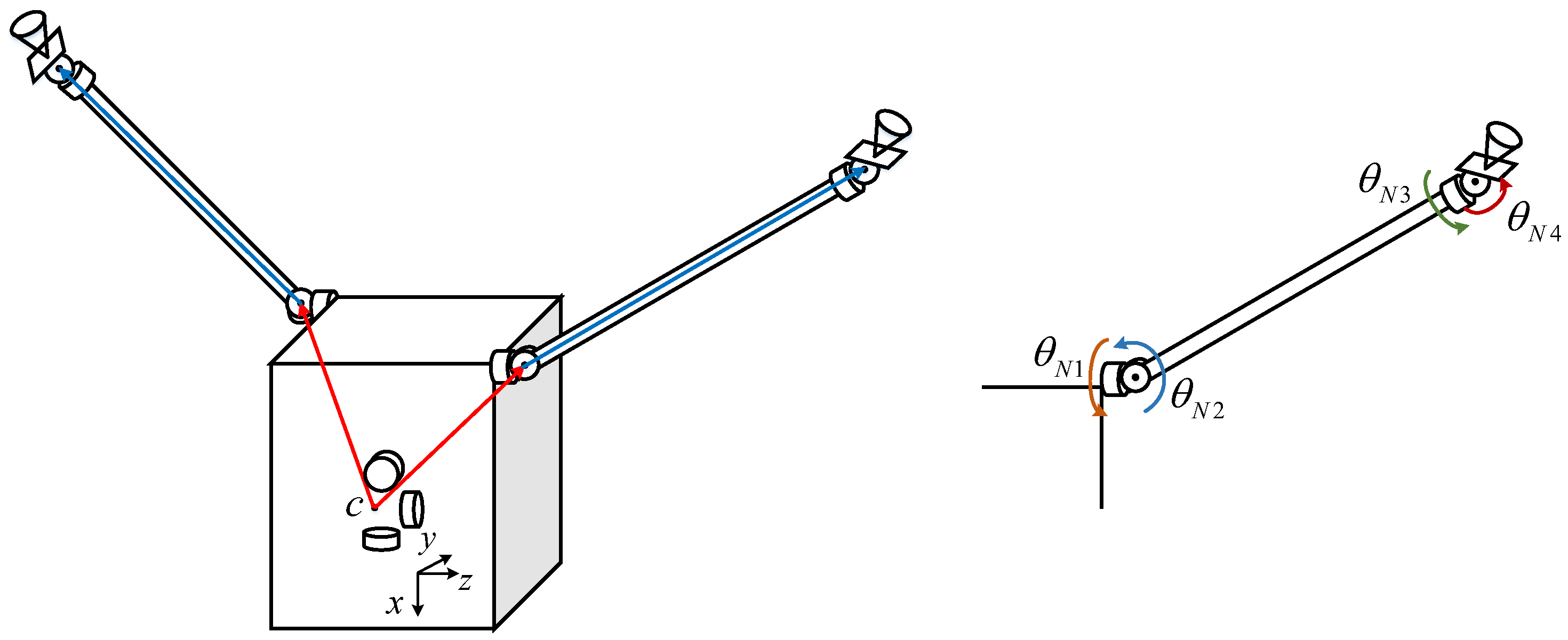
2.1. Mathematical Model of Spacecraft

The electric engines usually need to be aligned to a fixed position in space for a long time, which can lead to a significant reduction in the efficiency of the spacecraft if the engine is fixedly mounted on the spacecraft platform. In order to avoid such problems in the practical mission, electric engines can be mounted on the gimbaled thruster booms, as shown in Figure 1, which is described in the Ref. [6].
Based on the theory of the multi-body system, the dynamics model of the thruster booms and spacecraft platform can be established. The basic assumptions of the system are given, as follows.
Assumption 1. 
The thruster booms and the spacecraft platform are treated as rigid bodies, regardless of the effects of flexible vibration and liquid sloshing.
Assumption 2. 
The thruster boom joints are regarded as ideal hinges without considering non-linear factors such as flexibility and friction.
Assumption 3. 
The spacecraft is in a weightless environment, and the sum of environmental disturbances as well as modeling uncertainties is considered as a generalized disturbance.
This paper aims to complete the control of the thrust boom as well as the spacecraft platform, and a schematic of the system structure is given in Figure 2. First, the optimal joint angle of the thrust boom can be obtained according to the orbital control requirements, but the specific acquisition process is not studied in this paper. This joint angle is considered to be the desired signal for the controller design of thrust boom. Further, considering that the motion of the thrust boom will cause the instability of the spacecraft platform, a fast attitude stabilization controller is designed in the lower part of Figure 2 to ensure the high precision stability of the spacecraft attitude.
According to the above assumptions, the dynamics equations of the thruster booms and the spacecraft platform are obtained using the Lagrangian modeling method as
M Q Q ¨ + C Q , Q ˙ = τ + D
where M Q is the generalized inertia matrix of the combination, C Q , Q ˙ is a nonlinear term consisting of both centrifugal force and Coriolis force, D N is the unknown generalized disturbance. Q and τ denote the generalized coordinates and generalized forces, respectively
Q ˙ = ω T Θ ˙ N T Θ ˙ S T T τ = T T T N T T S T T
where ω denotes the angular velocity vector of the spacecraft body under the inertial system, T represents the control torque of the spacecraft platform under the inertial system, and Θ N = θ N 1 θ N 2 θ N 3 θ N 4 T and Θ S = θ S 1 θ S 2 θ S 3 θ S 4 T are the joint angles of the two thrust booms.
In particular, the spacecraft platform can be considered as stationary when it is observing a stationary target. Therefore, the dynamics model of two thruster booms can be simplified to the form of fixed bases, and the dynamic equations of the two booms are shown in Equation (3).
M Θ i Θ ¨ i + C Θ i , Θ ˙ i = T i T , i = N , S
where M Θ i is the inertia matrices of the thrust booms in the fixed-base mode, and C Θ i , Θ ˙ i is the nonlinear terms. It is obvious that the dynamics of the two thrust booms are identical, so only the controller design for the Θ group is required.

2.2. Preliminaries

Lemma 1 
(Predefined-time stable [27]). For a system x ˙ = f x , t , if there exists a candidate Lyapunov function V x : R n R + 0 , satisfying:
(1)
V 0 = 0 ;
(2)
V x > 0 x 0 ;
(3)
For x , the derivative of V x satisfies:
V ˙ π γ T c V 1 γ γ 2 2 + V 1 + γ γ 2 2
where T c > 0 , 0 < γ < 1 are constants. Then the system is predefined-time stable with the predefined-time T c .
Lemma 2 
(Practical predefined-time stable [28]). For a system x ˙ = f x , t , if there exists a candidate Lyapunov function V x : R n R + 0 , satisfying:
(1)
V 0 = 0 ;
(2)
V x > 0 x 0 ;
(3)
For x , the derivative of V x satisfies:
V ˙ π γ T c V 1 γ γ 2 2 + V 1 + γ γ 2 2 + υ
where T c > 0 , 0 < γ < 1 , 0 < υ < are constants. Then for any initial state, the system can converge within the bounds within a predefined-time.

3. Predefined-Time Controller Design for Thrust Boom

In this section, a predefined-time disturbance observer is introduced to handle the existing disturbances at first. Based on this, a second-order sliding mode control algorithm with a predefined-time convergence is proposed for the control of the thrust booms.
In actual orbiting missions, the joint angle Θ d , angular velocity Θ ˙ d and angular acceleration Θ ¨ d of the thrust booms are usually solved in advance according to the energy optimum and other requirements. Therefore, the tracking error of the thrust booms can be expressed as
E 1 = Θ Θ d E 2 = Θ ˙ Θ ˙ d

3.1. Predefined-Time Disturbance Observer

Based on the fixed-base dynamic equations of thrust boom (3) and considering the uncertainties disturbance, the thrust boom tracking error dynamics equation is expressed as
E ˙ 2 = M Θ 1 C Θ , Θ ˙ + M Θ 1 D + M Θ 1 T T Θ ¨ d
For brevity, mark M Θ 1 D as d .
Define the observation error of state error E 2 as
s d = E ^ 2 E 2
The state observer is designed to
E ^ ˙ 2 = π γ d T d 1 2 1 γ d γ d 2 2 sig 1 γ d s d + 1 2 1 + γ d γ d 2 2 sig 1 + γ d s d k ^ d sgn s d M Θ 1 C Θ , Θ ˙ Θ ¨ d sgn s d + M Θ 1 T
k ^ ˙ d = ρ d s d μ d k ^ d d ^ max
d ^ ˙ max = δ d k ^ d d ^ max
where T c > 0 , 0 < γ < 1 are constants. Symbol ‘∘’ is defined as the multiplication of numbers in the corresponding positions of two vectors. For example, if a = a 1 a 2 a n T and b = b 1 b 2 b n T , then
a b = a 1 b 1 a 2 b 2 a n b n T
The disturbance observer is designed as
d ^ = π γ d T d 1 2 1 γ d γ d 2 2 sig 1 γ d s d + 1 2 1 + γ d γ d 2 2 sig 1 + γ d s d k ^ d sgn s d M Θ 1 C Θ , Θ ˙ Θ ¨ d sgn s d + M Θ 1 C Θ , Θ ˙ + Θ ¨ d
Theorem 1. 
For the thrust boom system consisting of Equation (3), with the state observer (9) and the disturbance observer (13), the external disturbance d to the system can be estimated accurately in predefined-time T d .
Proof. 
According to Equations (9)–(11), the derivative of the state estimation error is the same as the observation error of the disturbance observer
s ˙ d = E ^ ˙ 2 E ˙ 2 = d ^ d = π γ d T d 1 2 1 γ d γ d 2 2 sig 1 γ d s d + 1 2 1 + γ d γ d 2 2 sig 1 + γ d s d k ^ d sgn s d M Θ 1 C Θ , Θ ˙ Θ ¨ d sgn s d M Θ 1 C Θ , Θ ˙ Θ ¨ d d
The Lyapunov function is chosen as
V d = 1 2 s d T s d + 1 2 ρ d k ^ d d max T k ^ d d max + μ d 2 δ d d ^ max d max T d ^ max d max
The derivative of Equation (15), one has
V ˙ d = s d T s ˙ d + 1 ρ d k ^ d d max T k ^ ˙ d + μ d δ d d ^ max d max T d ^ ˙ max
Bringing Equations (10), (11) and (14) into Equation (16), one has
V ˙ d = s d T M Θ 1 C Θ , Θ ˙ Θ ¨ d d π γ d T d 1 2 1 γ d γ d 2 2 sig 1 γ d s d + 1 2 1 + γ d γ d 2 2 sig 1 + γ d s d k ^ d sgn s d M Θ 1 C Θ , Θ ˙ Θ ¨ N d sgn s d + 1 ρ d k ^ d d max T ρ d s d μ d k ^ d d ^ max + μ d δ d d ^ max d max T δ d k ^ d d ^ max
Further simplification leads to
V ˙ d = π s d T γ d T d 1 2 1 γ d γ d 2 2 sig 1 γ d s d + 1 2 1 + γ d γ d 2 2 sig 1 + γ d s d k ^ d T s d M Θ 1 C Θ , Θ ˙ Θ ¨ d T s d s d T d s d T M Θ 1 C Θ , Θ ˙ + Θ ¨ d + k ^ d d max T s d μ d k ^ d T k ^ d d ^ max + μ d d max k ^ d d ^ max μ d d max k ^ d d ^ max + μ d d ^ max T k ^ d d ^ max π γ d T d s d T 1 2 1 γ d γ d 2 2 si g 1 γ d s d + 1 2 1 + γ d γ d 2 2 si g 1 + γ d s d s d T d d max T s d μ d k ^ d d ^ max T k ^ d d ^ max π γ d T d s d T 1 2 1 γ d γ d 2 2 si g 1 γ d s d + 1 2 1 + γ d γ d 2 2 si g 1 + γ d s d μ d k ^ d d ^ max T k ^ d d ^ max 0
It can be observed that the system is asymptotically stable, so both the state estimation error and the disturbance estimation error can converge to 0. In turn, Equation (19) holds
π k ^ d d max T γ d T d 1 2 1 γ d γ d 2 2 sig 1 γ d k ^ d d max + 1 2 1 + γ d γ d 2 2 sig 1 + γ d k ^ d d max Δ d 1 π d ^ max d max T γ d T d 1 2 1 γ d γ d 2 2 sig 1 γ d d ^ max d max + 1 2 1 + γ d γ d 2 2 sig 1 + γ d d ^ max d max Δ d 2
Further processing of Equation (18) has
V ˙ d π s d T γ d T d 1 2 1 γ d γ d 2 2 sig 1 γ d s d + 1 2 1 + γ d γ d 2 2 si g 1 + γ d s d π γ d T d k ^ d d max T 1 2 1 γ d γ d 2 2 sig 1 γ d k ^ d d max + 1 2 1 + γ d γ d 2 2 si g 1 + γ d k ^ d d max π γ d T d d ^ max d max T 1 2 1 γ d γ d 2 2 si g 1 γ d k ^ d d max + 1 2 1 + γ d γ d 2 2 si g 1 + γ d k ^ d d max + Δ d 1 + Δ d 2 π γ d T d V d 1 d d 2 2 + V d 1 + d d 2 2 + Δ d 1 + Δ d 2
According to Lemma 2, the estimation error of the disturbance observer satisfies the practical predefined-time stable. The bound of the final convergence gradually decreases to 0 as time goes on. □

3.2. Predefined-Time Controller Design Base on Second-Order Sliding Mode

Compared with the traditional first-order sliding mode controller, the second-order sliding mode controller has higher robustness and none of the chattering problem. In this section, the second-order sliding mode is used to design the control algorithm, and the sliding surface 1 is selected as
S 1 = E 2 + F 0
F 0 is denoted as
F 0 = π γ 0 T 0 1 2 1 γ 0 γ 0 2 2 sig 1 γ 0 E 1 + 1 2 1 + γ 0 γ 0 2 2 sig 1 + γ 0 E 1
where, T 0 > 0 , 0 < γ 0 < 1 are constants.
Taking the derivative of sliding surface(21), one can have
S ˙ 1 = E ˙ 2 + F ˙ 0 = M Θ 1 C Θ , Θ ˙ + M Θ 1 D + M Θ 1 T Θ ¨ d + F ˙ 0
According to the equivalence control principle, one has T = T e q + T r , thus
T e q = C Θ , Θ ˙ + M Θ Θ ¨ d F ˙ 0
where, T e q is the equivalent control law when the system state is located on the sliding surface. Further the derivative of T r is designed to reduce the chattering problem of the controller when the state of the system is approaching S 1 = 0 . Sliding surface 2 is designed as
S 2 = S ˙ 1 + F 1
F 1 is denoted as
F 1 = π γ 1 T 1 1 2 1 γ 1 γ 1 2 2 sig 1 γ 1 S 1 + 1 2 1 + γ 1 γ 1 2 2 sig 1 + γ 1 S 1
where, T 1 > 0 , 0 < γ 1 < 1 are constants.
Taking the derivative of the Equation (25), one can have
S ˙ 2 = S ¨ 1 + F ˙ 1
Bringing Equation (24) into (23), one has
S ˙ 1 = M Θ 1 C Θ , Θ ˙ + M Θ 1 D + M Θ 1 T r Θ ¨ d + F ˙ 0 + M Θ 1 C Θ , Θ ˙ + M Θ Θ ¨ d F ˙ 0 = d + M Θ 1 T r
Thus, the derivation of Equation (28) is written as
S ¨ 1 = d ˙ + d d t M Θ 1 T r
Design the reaching law of the sliding surface S 2 as
S ˙ 2 = F 2
where, F 2 is indicated by
F 2 = π γ 2 T 2 1 2 1 γ 2 γ 2 2 2 sig 1 γ 2 S 2 + 1 2 1 + γ 2 γ 2 2 2 sig 1 + γ 2 S 2
where, T 2 > 0 , 0 < γ 2 < 1 are constants.
Therefore, according to Equation (27), it can be known that
d ˙ + d d t M Θ 1 T r = F 2 F ˙ 1
Since d is the disturbance of the system, its value can be replaced by the estimated value of the disturbance observer in the control torque T r , T r is designed as
T r = M Θ 0 t F 2 d t F 1 d ^ K sgn 0 t S 2 d t
where K = diag k 1 , k 2 , k 3 , k 4 is used to handle the estimated residuals of disturbances in the system. Since the estimated error of the disturbance observer (13) is able to converge to a bound determined by Δ d 1 and Δ d 2 within a predefined time, it is sufficient to take the larger value for each parameter in K .
Theorem 2. 
For the thrust boom system (3), the joint angles of thrust boom are able to track on the desired signal within a predefined time under the controller (34) with the sliding surfaces (21) and (25).
T = T e q + T r = C Θ , Θ ˙ + M Θ Θ ¨ d F ˙ 0 + M Θ 0 t F 2 d t F 1 M Θ d ^ + K sgn 0 t S 2 d t
Proof. 
First, the properties of the sliding mode surface S 2 is analyzed and the Lyapunov function is chosen as
V 2 = 1 2 S 2 T S 2
The derivative of (35) is
V ˙ 2 = S 2 T S ˙ 2 = S 2 T S ¨ 1 + F ˙ 1 = S 2 T d ˙ + d d t M Θ 1 T r + F ˙ 1
Bringing (32) into the above Equation (36), one has
V ˙ 2 = S 2 T d ˙ + F ˙ 1 + S 2 T d d t 0 t F 2 d t F ˙ 1 d ^ K sgn 0 t S 2 d t = S 2 T d ˙ + F ˙ 1 + S 2 T 0 t F 2 d t F ˙ 1 d d t d ^ + K sgn 0 t S 2 d t = S 2 T F 2 S 2 T d d t d ^ + K sgn 0 t S 2 d t d = S 2 T F 2 S 2 T d ^ ˙ + K sgn S 2 d ˙ = S 2 T F 2 S 2 T K sgn S 2 d ˜ ˙
Substituting F 2 into Equation (37), one can have
V ˙ 2 π S 2 T γ 2 T 2 1 2 1 γ 2 γ 2 2 2 sig 1 γ 2 S 2 + 1 2 1 + γ 2 γ 2 2 2 sig 1 + γ 2 S 2 = π γ 2 T 2 V 2 1 γ 2 γ 2 2 2 + V 2 1 + γ 2 γ 2 2 2
Based on this, it is known that the sliding surface S 2 is able to converge to S 2 = 0 within a predefined time. When S 2 = 0 , one has
S ˙ 1 = F 1
Next, the Lyapunov function is taken as
V 1 = 1 2 S 1 T S 1
The derivation of the Lyapunov function (40) is
V ˙ 1 = S 1 T S ˙ 1 = π S 1 T γ 1 T 1 1 2 1 γ 1 γ 1 2 2 si g 1 γ 1 S 1 + 1 2 1 + γ 1 γ 1 2 2 si g 1 + γ 1 S 1 = π γ 1 T 1 V 1 1 γ 1 γ 1 2 2 + V 1 1 + γ 1 γ 1 2 2
It is obvious that the sliding surface S 1 can converge to 0 within a predefined time. On this basis, the stability of the system state E 1 is analyzed. When S 1 = 0 , one has
E ˙ 1 = F 1
The candidate Lyapunov function is chosen as
V 0 = 1 2 E 1 T E 1
The derivative of (43) is
V ˙ 0 = E 1 T E ˙ 1 = E 1 T E 2
Substitute Equation (42) into (43), one can have
V ˙ 0 = E 1 T E ˙ 1 = π E 1 T γ 0 T 0 1 2 1 γ 0 γ 0 2 2 si g 1 γ d E 1 + 1 2 1 + γ 0 γ 0 2 2 si g 1 + γ 0 E 1 = π γ 0 T 0 V 0 1 γ 0 γ 0 2 2 + V 0 1 + γ 0 γ 0 2 2 0
It can be observed that after the system state E 1 converges to S 1 = 0 , E 1 is able to converge to E 1 = 0 within a predefined time. By V ˙ 0 0 , the Lyapunov function V 0 is non-increasing. Therefore, when the system state E 1 converges to 0, ones have V 0 0 , E 1 0 , and E 2 = E ˙ 1 0 . In summary, the system state is able to converge to the equilibrium point. □

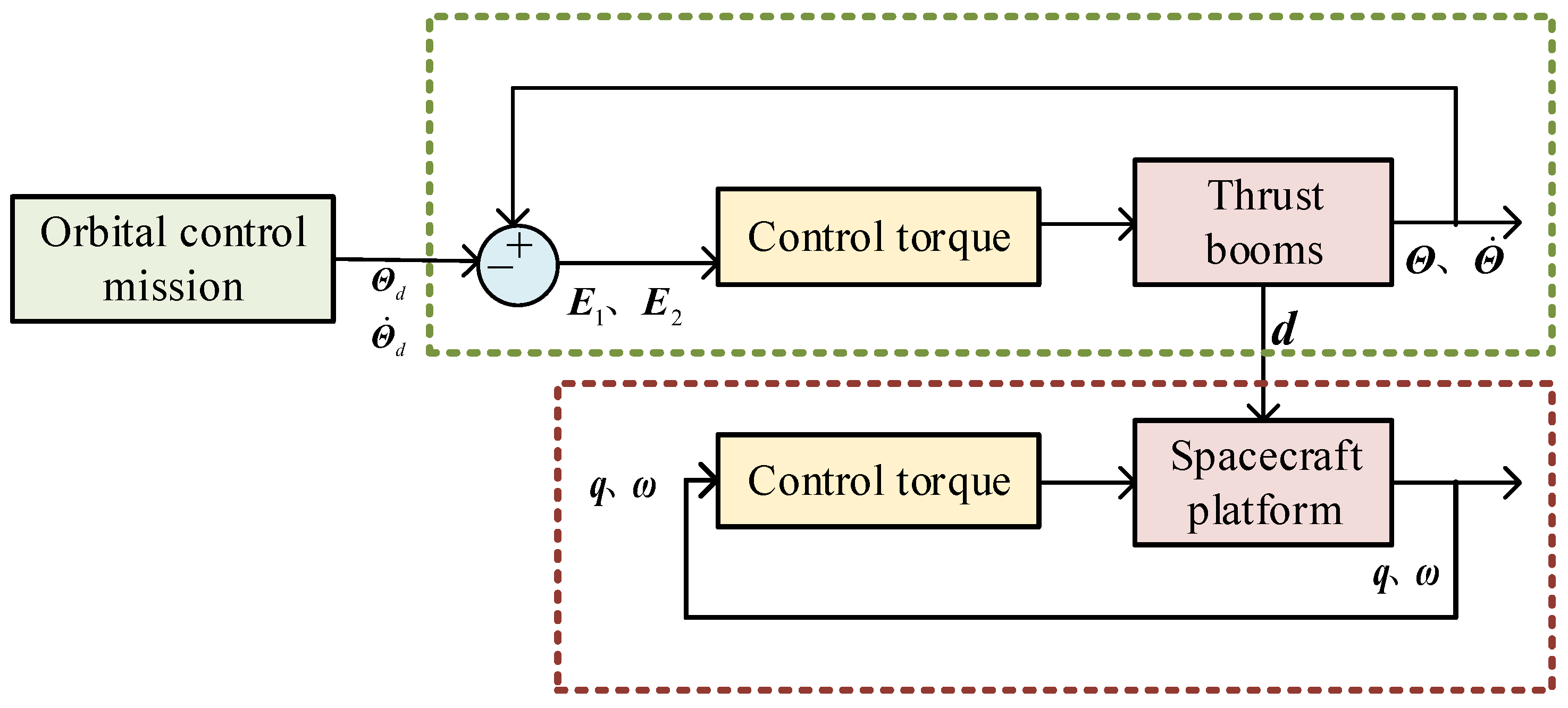
4. Predefined-Time Attitude Stable for Spacecraft

The thrust booms motion is regarded as a unknown external disturbance to the spacecraft body, and the attitude stabilization of the spacecraft body is achieved by using a predefined-time controller similar to (34). At this point, the dynamic equation of the spacecraft can be simplified to
ω ˙ b = J 1 ω b × J ω b + J 1 T b + J 1 T r d b + d b q ˙ 0 = 1 2 q v T ω b q ˙ v = 1 2 E q v ω b
where, E q v = 1 2 ( q v × + q 0 I 3 ) . Disturbance d b mainly consists of the force of the thrust booms on the spacecraft. Since the control objective is to make the spacecraft platform attitude stable, it is defined that
Q 0 = 0 T Θ T Θ S T T
According to the dynamic Equation (1), one has
τ 0 = M Q 0 Q ¨ 0 + C Q 0 , Q ˙ 0
where the joint angular velocity and joint angular acceleration can be measured by the servo systems. Thus, the feedforward control torque is
T r d b = A b i τ 0 ( 1 ) τ 0 ( 2 ) τ 0 ( 3 ) T
where A b i is the transformation matrix from the inertial system to the spacecraft-based system.
The control torque of the system is designed as
T b = T r d b + ω b × J ω b J F ˙ 0 b J 0 t F 2 b d t F 1 b d ^ b K b sgn 0 t S 2 b d t
where K b is chosen a value and F 0 b , F 1 b , and F 2 b are denoted as
F 0 b = 2 π E q v 1 γ 0 b T 0 b 1 2 1 γ 0 b γ 0 b 2 2 sig 1 γ 0 b q v + 1 2 1 + γ 0 b γ 0 b 2 2 sig 1 + γ 0 b q v F 1 b = π γ 1 b T 1 b 1 2 1 γ 1 b γ 1 b 2 2 sig 1 γ 1 b S 1 b + 1 2 1 + γ 1 b γ 1 b 2 2 sig 1 + γ 1 b S 1 b F 2 b = π γ 2 b T 2 b 1 2 1 γ 2 b γ 2 b 2 2 sig 1 γ 2 b S 2 b + 1 2 1 + γ 2 b γ 2 b 2 2 sig 1 + γ 2 b S 2 b
The sliding surfaces are designed as
S 1 b = ω b + F 0 b S 2 b = S ˙ 1 b + F 1 b
d ^ b is the disturbance received by the spacecraft, which can be estimated by the observer (53).
d ^ b = π γ d T d 1 2 1 γ d γ d 2 2 sig 1 γ d s d b + 1 2 1 + γ d γ d 2 2 sig 1 + γ d s d b k ^ d sgn s d b J 1 ω b × J ω b + T r d b sgn s d b + J 1 ω b × J ω b T r d b
where s d b is the estimated error between the estimate value and the actual value, which can be written as
s d b = ω ^ b ω b
The derivative of ω ^ b is expressed as
ω ^ ˙ b = J 1 ω b × J ω b + J 1 T b + J 1 T r d b + d ^ b
Theorem 3. 
Consider a electric propulsion spacecraft attitude dynamic, such as Equation (46). The attitude can be stable within a predefined-time under the developed predefined-time controller (50) and the predefined-time disturbance observer (53).
Proof. 
This part of the controller and the observer are proved in a similar way to the thrust booms part. Therefore, the proof process is omitted for brevity. □
Synthesis of Section 3 and Section 4; the schematic diagram of the control system structure of this paper is given in Figure 3.
Remark 1. 
The proposed control algorithm is theoretically capable of tracking arbitrary constant-value signals or time-varying signals, but is limited by the actual capacity of the spacecraft in the practical engineering.

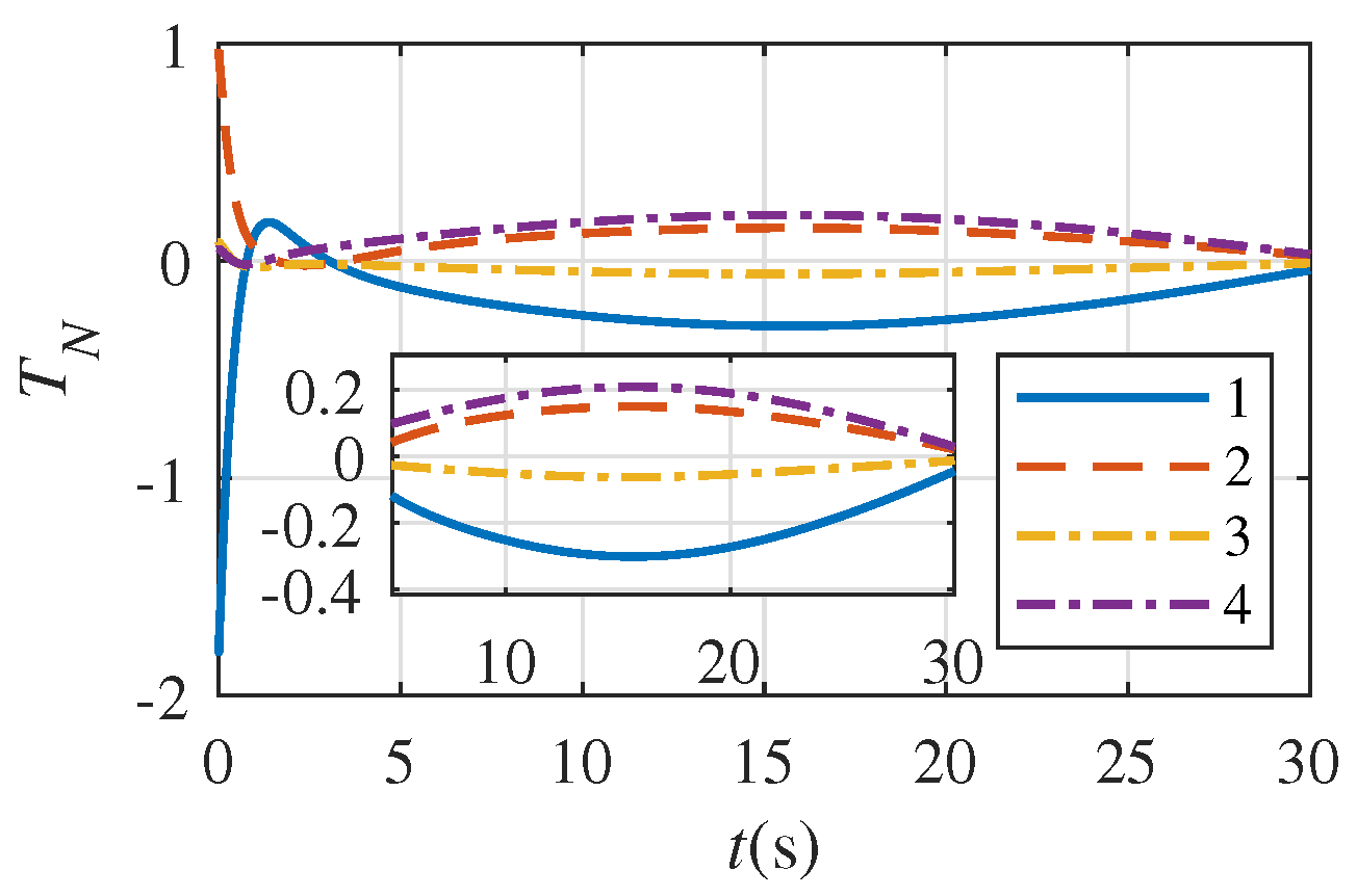
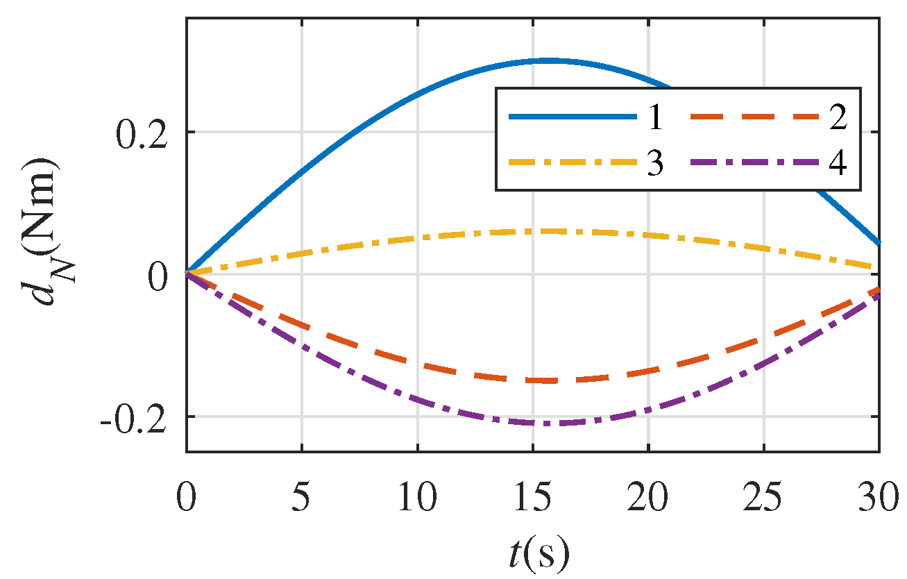
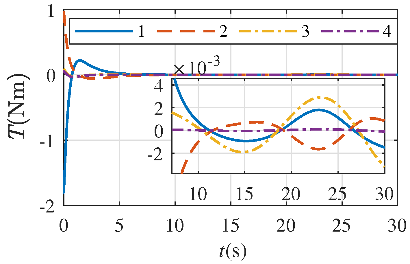
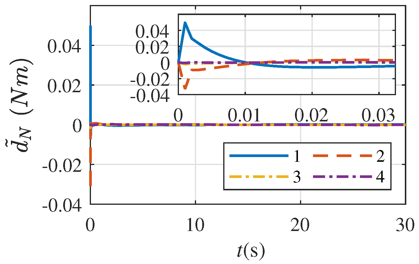
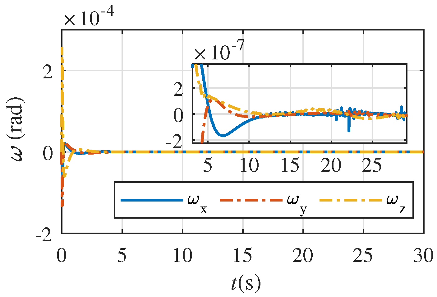
5. Numerical Simulation Example

In this section, the effectiveness of the proposed algorithm is illustrated by a simulation case. The spacecraft parameters are shown in the Table 1.
The controller parameters are selected as T 0 = 8 , γ 0 = 0.2 , T 1 = 8 , γ 1 = 0.7 , T 2 = 3 , γ 2 = 0.2 , K = [ 0.2 0.2 0.2 0.2 ] , T 0 b = 8 , γ 0 b = 0.7 , T 1 b = 8 , γ 1 b = 0.7 , T 2 b = 2 , γ 0 b = 0.7 , K b = [ 0.1 0.1 0.1 ] .
The disturbance observer parameters are selected as T d = 0.1 , γ d = 0.2 , ρ d = 1 , μ d = 5 , δ d = 10 , T d b = 0.2 , γ d b = 1 , ρ d b = 1 , μ d b = 5 , δ d = 10 .
The response curve of the joint angles of the thrust boom are given in Figure 4, from which it can be observed that the joint angles can quickly track the desired signal about 10s under the controller (34). This ensures that the spacecraft system can accomplish the specified orbit control task.
The control torque required for each joint angle of the thrust boom is given in Figure 5, in which the labels 1–4 are abbreviated for θ N 1 θ N 4 . The disturbance torque for each joint are given in Figure 6. Compared with Figure 5, it can be observed that the control torque is approximately the same as the opposite of the disturbance torque after the system tracking of the target signal.
Further, the control torque remaining after removing the torque used to counteract the disturbance is given in Figure 7. From the response curves, it can be observed that the remaining control torque of θ N 1 and θ N 3 vary basically with the frequency of the desired signal. Since the desired signal of θ N 4 is 0, the control torque of this joint angle is finally stabilized at 0. Although the desired signal of θ N 2 is 0, since θ N 2 is not an end joint, the required control torque of θ N 3 will be transmitted to θ N 2 , so it is in line with the actual situation that the control torque is not zero.
The estimated error of the disturbance observer is given in Figure 8. It can be observed that the observation error can converge to zero in a short time, ensuring that the thrust boom can track the desired signal with high accuracy.
The response curves for the attitude quaternion and attitude angular velocity of the spacecraft are given in Figure 9 and Figure 10, and the control torque of the spacecraft is given in Figure 11. It can be observed that the spacecraft platform is always in a stable state under the action of the controller (50). This ensures that the electric thrust engine works while the spacecraft body is able to perform other observation tasks.

6. Conclusions

This paper designs a predefined-time attitude stabilization controller and thrust boom tracking controller for electric spacecraft with thrust booms. To deal with the disturbance without prior knowledge, a novel predefined-time disturbance observer is developed. Then, through combining second-order sliding mode control with a predefined-time stable, a new control algorithm is proposed, ensuring the spacecraft plateform and joint angles of thrust booms can converge to the sliding surface within a predefined time, then they can converge to the equilibrium point along the sliding surface within a predefined time. The simulation results prove the feasibility of the designed control algorithm.

Author Contributions

Conceptualization, X.K. and Y.S.; methodology, X.K. and Y.G. (Yanning Guo); validation, X.K.; writing—original draft preparation, X.K.; writing—review and editing, X.K., Y.G. (Youmin Gong) and G.M.; supervision, Y.G. (Yanning Guo); project administration, X.K. All authors have read and agreed to the published version of the manuscript.

Funding

This research received no external funding.

Data Availability Statement

Not applicable.

Acknowledgments

This work is supported by the National Natural Science Foundation of China (Grant No. 61973100, Grant No. 62273118, Grant No. 12150008).

Conflicts of Interest

The authors declare no conflict of interest.

References

  1. Walsh, A.; Di Cairano, S.; Weiss, A. MPC for coupled station keeping, attitude control, and momentum management of low-thrust geostationary satellites. In Proceedings of the 2016 American Control Conference (ACC), Boston, MA, USA, 6–8 July 2016; pp. 7408–7413. [Google Scholar]
  2. Martinez-Sanchez, M.; Pollard, J.E. Spacecraft electric propulsion—An overview. J. Propuls. Power 1998, 14, 688–699. [Google Scholar] [CrossRef] [Green Version]
  3. Wei, Y.; Yan, H.; Liu, X.; Yu, Y.; Geng, J.; Chen, T.; Fu, T.; Su, G.; Hu, Y.; Han, D. The View of Micropropulsion Technology for China’s Advanced Small Platforms in Deep Space. Space Sci. Technol. 2022, 2022, 9769713. [Google Scholar] [CrossRef]
  4. Wertz, J.R.; Larson, W.J.; Kirkpatrick, D.; Klungle, D. Space Mission Analysis and Design; Springer: Dordrecht, The Netherlands, 1999; Volume 8. [Google Scholar]
  5. Herman, D.A.; Soulas, G.C.; Van Noord, J.L.; Patterson, M.J. NASA’s evolutionary xenon thruster (NEXT) long-duration test results. J. Propuls. Power 2012, 28, 625–635. [Google Scholar] [CrossRef]
  6. Caverly, R.; Di Cairano, S.; Weiss, A. Control Allocation and Quantization of a GEO Satellite with 4DOF Gimbaled Thruster Booms. In Proceedings of the AIAA Scitech 2020 Forum, Orlando, FL, USA, 6–10 January 2020; p. 1687. [Google Scholar]
  7. Gazzino, C.; Arzelier, D.; Louembet, C.; Cerri, L.; Pittet, C.; Losa, D. Long-term electric-propulsion geostationary station-keeping via integer programming. J. Guid. Control Dyn. 2019, 42, 976–991. [Google Scholar] [CrossRef]
  8. Leomanni, M.; Bianchini, G.; Garulli, A.; Giannitrapani, A.; Quartullo, R. Orbit control techniques for space debris removal missions using electric propulsion. J. Guid. Control Dyn. 2020, 43, 1259–1268. [Google Scholar] [CrossRef]
  9. Caverly, R.J.; Di Cairano, S.; Weiss, A. Electric Satellite Station Keeping, Attitude Control, and Momentum Management by MPC. IEEE Trans. Control Syst. Technol. 2020, 29, 1475–1489. [Google Scholar] [CrossRef]
  10. Li, B.; Qin, K.; Xiao, B.; Yang, Y. Finite-time extended state observer based fault tolerant output feedback control for attitude stabilization. ISA Trans. 2019, 91, 11–20. [Google Scholar] [CrossRef]
  11. Nagesh, I.; Edwards, C. A multivariable super-twisting sliding mode approach. Automatica 2014, 50, 984–988. [Google Scholar] [CrossRef] [Green Version]
  12. Liu, Z.; Liu, J.; Wang, L. Disturbance observer based attitude control for flexible spacecraft with input magnitude and rate constraints. Aerosp. Sci. Technol. 2018, 72, 486–492. [Google Scholar] [CrossRef]
  13. Zhang, C.; Dai, M.Z.; Wu, J.; Xiao, B.; Li, B.; Wang, M. Neural-networks and event-based fault-tolerant control for spacecraft attitude stabilization. Aerosp. Sci. Technol. 2021, 114, 106746. [Google Scholar] [CrossRef]
  14. Zhang, Z.; Li, Y. An AEFA-Based Optimum Design of Fuzzy PID Controller for Attitude Control Flywheel with BLDC Motor. Aerospace 2022, 9, 789. [Google Scholar] [CrossRef]
  15. Hu, Q.; Li, B.; Xiao, B.; Zhang, Y. Spacecraft attitude fault-tolerant control based on iterative learning observer and control allocation. In Control Allocation for Spacecraft Under Actuator Faults; Springer: Singapore, 2021; pp. 133–155. [Google Scholar]
  16. Miao, Y.; Hwang, I.; Liu, M.; Wang, F. Adaptive fast nonsingular terminal sliding mode control for attitude tracking of flexible spacecraft with rotating appendage. Aerosp. Sci. Technol. 2019, 93, 105312. [Google Scholar] [CrossRef]
  17. Xia, X.; Jia, Y.; Wang, X.; Zhang, J. Neural-Network-Based Terminal Sliding Mode Control of Space Robot Actuated by Control Moment Gyros. Aerospace 2022, 9, 730. [Google Scholar] [CrossRef]
  18. Fu, J.; Liu, M.; Cao, X.; Li, A. Robust neural-network-based quasi-sliding-mode control for spacecraft-attitude maneuvering with prescribed performance. Aerosp. Sci. Technol. 2021, 112, 106667. [Google Scholar] [CrossRef]
  19. Pukdeboon, C. Optimal sliding mode controllers for attitude stabilization of flexible spacecraft. Math. Probl. Eng. 2011, 2011, 863092. [Google Scholar] [CrossRef]
  20. Tiwari, P.M.; Janardhanan, S.U.; un Nabi, M. Rigid spacecraft attitude control using adaptive integral second order sliding mode. Aerosp. Sci. Technol. 2015, 42, 50–57. [Google Scholar] [CrossRef]
  21. Hu, Q.; Niu, G. Attitude output feedback control for rigid spacecraft with finite-time convergence. ISA Trans. 2017, 70, 173–186. [Google Scholar] [CrossRef]
  22. Geng, Y.; Li, C.; Guo, Y.; Biggs, J.D. Fixed-time near-optimal control for repointing maneuvers of a spacecraft with nonlinear terminal constraints. ISA Trans. 2020, 97, 401–414. [Google Scholar] [CrossRef]
  23. Gao, S.; Liu, X.; Jing, Y.; Dimirovski, G.M. A novel finite-time prescribed performance control scheme for spacecraft attitude tracking. Aerosp. Sci. Technol. 2021, 118, 107044. [Google Scholar] [CrossRef]
  24. Hua, B.; Zhong, S.; Wu, Y.; Chen, Z. Research into a Consistency Cooperative Control Method for Attitude Orbit Coupling of SAR Satellite Formations under Communication Constraints. Aerospace 2022, 9, 556. [Google Scholar] [CrossRef]
  25. Du, H.; Zhang, J.; Wu, D.; Zhu, W.; Li, H.; Chu, Z. Fixed-time attitude stabilization for a rigid spacecraft. ISA Trans. 2020, 98, 263–270. [Google Scholar] [CrossRef] [PubMed]
  26. Zhou, Z.G.; Zhou, D.; Shi, X.N.; Li, R.F.; Kan, B.Q. Prescribed performance fixed-time tracking control for a class of second-order nonlinear systems with disturbances and actuator saturation. Int. J. Control 2021, 94, 223–234. [Google Scholar] [CrossRef]
  27. Muñoz-Vázquez, A.J.; Sánchez-Torres, J.D.; Gutiérrez-Alcalá, S.; Jiménez-Rodríguez, E.; Loukianov, A.G. Predefined-time robust contour tracking of robotic manipulators. J. Frankl. Inst. 2019, 356, 2709–2722. [Google Scholar] [CrossRef]
  28. Xie, S.; Chen, Q. Adaptive nonsingular predefined-time control for attitude stabilization of rigid spacecrafts. IEEE Trans. Circuits Syst. II Express Briefs 2021, 69, 189–193. [Google Scholar] [CrossRef]
Figure 1. Electric engines spacecrafts with thruster booms [6].
Aerospace 10 00094 g001
Figure 2. System structure.
Aerospace 10 00094 g002
Figure 3. Control system structure.
Aerospace 10 00094 g003
Figure 4. Tracking curve of joint angle.
Aerospace 10 00094 g004
Figure 5. Control torque of joints.
Aerospace 10 00094 g005
Figure 6. Disturbance torque of joints.
Aerospace 10 00094 g006
Figure 7. Control torque without disturbance.
Aerospace 10 00094 g007
Figure 8. Estimation error.
Aerospace 10 00094 g008
Figure 9. The response curve of attitude quaternion.
Aerospace 10 00094 g009
Figure 10. Angular velocity of spacecraft.
Aerospace 10 00094 g010
Figure 11. Control torque of spacecraft.
Aerospace 10 00094 g011
Table 1. Spacecraft parameters.
ParametersBase1N1N3N4S1S2S3S4
Mass (kg)50036323632
a i (m)000000000
00.03800.03800.03800.0380
000.1500.07500.1500.075
b i (m)0.356−0.35600000000
−0.4910.49100000000
0.491−0.4910.0620.150.0620.160.0620.150.0620.16
moment of inertia ( kg · m 2 ) I x x 1500.0330.150.0330.0520.0330.150.0330.052
I y y 1500.0170.150.0170.0520.0170.150.0170.052
I z z 1200.0260.0750.0260.020.0260.0750.0260.02
I x y 0.2600000000
I x z 0.3700000000
I y z −0.2900000000
Disclaimer/Publisher’s Note: The statements, opinions and data contained in all publications are solely those of the individual author(s) and contributor(s) and not of MDPI and/or the editor(s). MDPI and/or the editor(s) disclaim responsibility for any injury to people or property resulting from any ideas, methods, instructions or products referred to in the content.

