Effect of Working Current on C12A7 Hollow Cathode
Abstract
:1. Introduction
2. Experimental and Model Setup
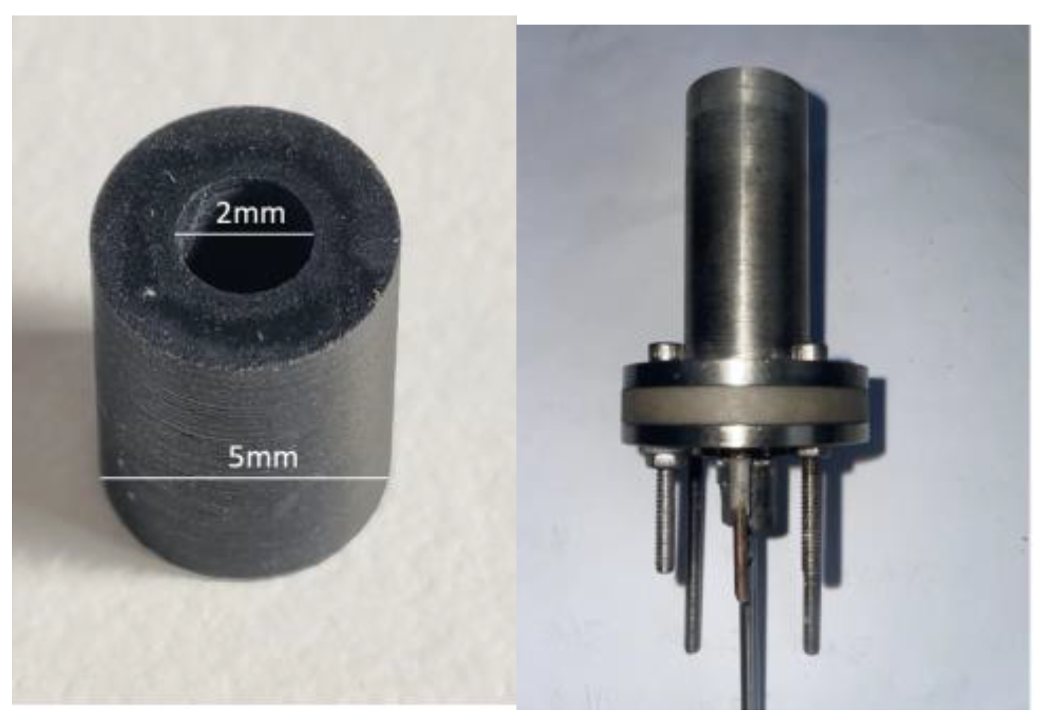
2.1. C12A7 Hollow Cathode
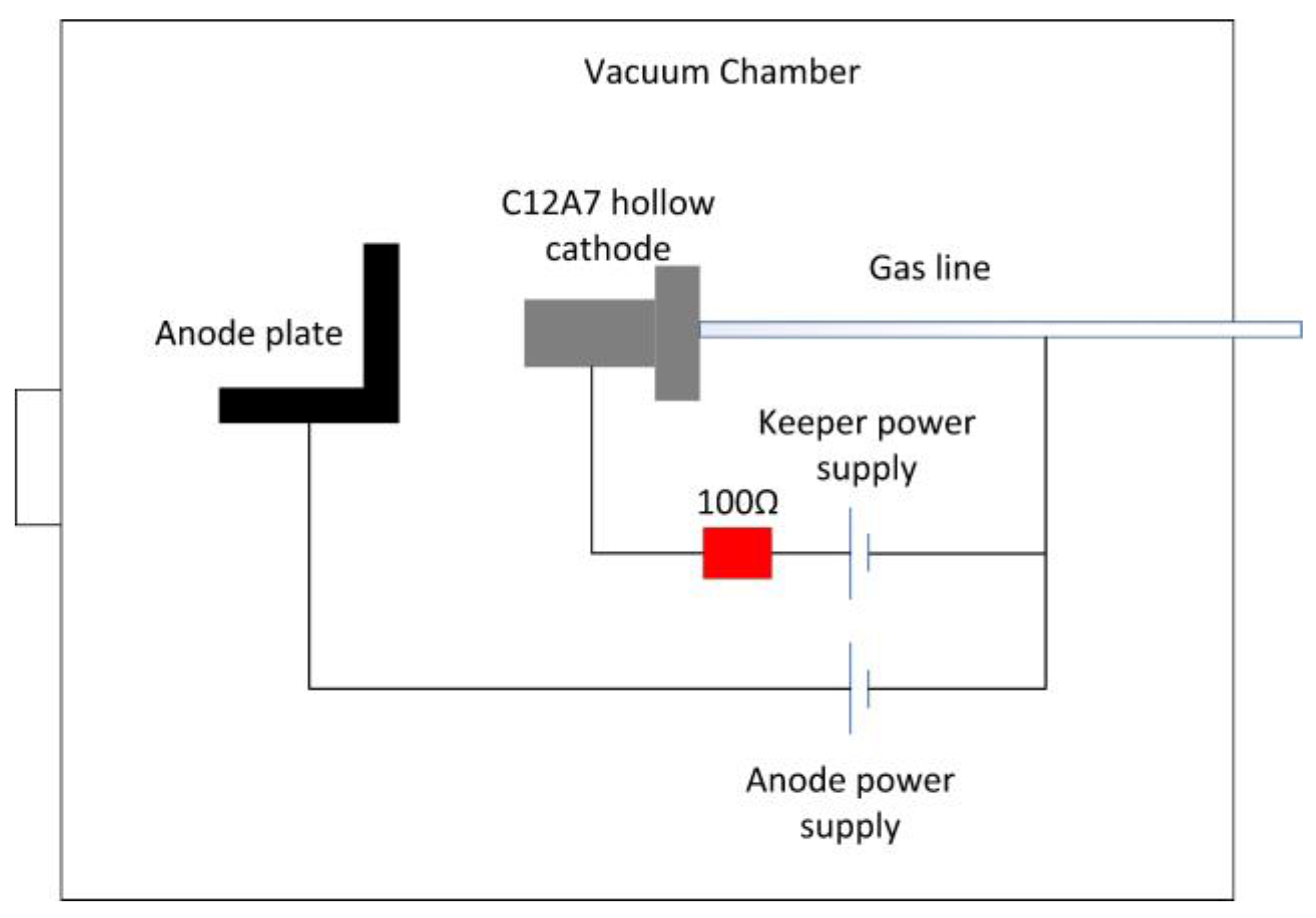
2.2. Testing Facility
2.3. Experimental Procedure
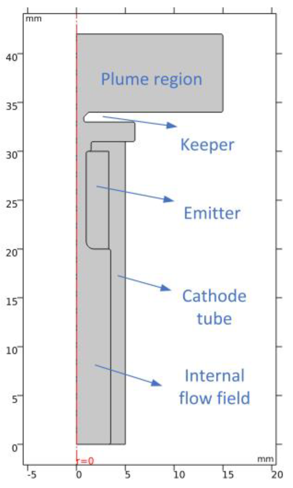
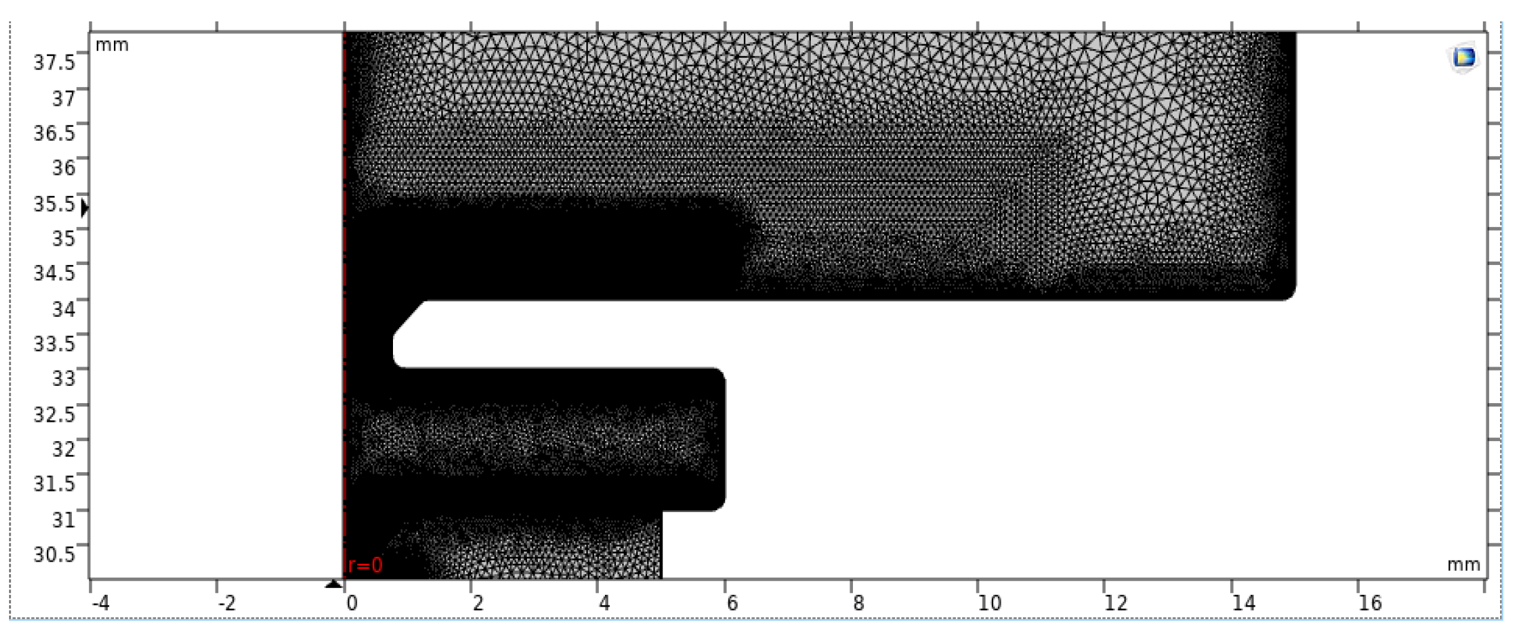
2.4. Model Construction
2.5. Physical Parameters of C12A7 Electride
2.6. Model Verification
3. Results and Discussion
3.1. Low Working Current
3.2. High Working Current
4. Conclusions
Author Contributions
Funding
Data Availability Statement
Conflicts of Interest
References
- Dale, E.; Jorns, B.; Gallimore, A. Future directions for electric propulsion research. Aerospace 2020, 7, 120. [Google Scholar] [CrossRef]
- Iess, L.; Bruno, C.; Ulivieri, C.; Ponzi, U.; Parisse, M.; Laneve, G.; Vannaroni, G.; Dobrowolny, M.; De Venuto, F.; Bertotti, B.; et al. Satellite de-orbiting by means of electrodynamic tethers part i: General concepts and requirements. Acta Astronaut. 2002, 50, 399–406. [Google Scholar] [CrossRef]
- Lev, D.; Myers, R.M.; Lemmer, K.M.; Kolbeck, J.; Koizumi, H.; Polzin, K. The technological and commercial expansion of electric propulsion. Acta Astronaut. 2019, 159, 213–227. [Google Scholar] [CrossRef]
- Lev, D.R.; Mikellides, I.G.; Pedrini, D.; Goebel, D.M.; Jorns, B.A.; McDonald, M.S. Recent progress in research and development of hollow cathodes for electric propulsion. Plasma Phys. 2019, 3, 6. [Google Scholar] [CrossRef]
- Rand, L.; Williams, J.; Hoyt, R. Hollow Cathode with Electride Insert. In Proceedings of the AIAA/ASME/SAE/ASEE Joint Propulsion Conference & Exhibit, San Diego, CA, USA, 31 July–3 August 2011. [Google Scholar]
- Drobny, C.; Tajmar, M. Development of a C12A7 Electride Hollow Cathode. In Proceedings of the 52nd AIAA/SAE/ASEE Joint Propulsion Conference, Salt Lake City, UT, USA, 25–27 July 2016; p. 3124751. [Google Scholar]
- Mcdonald, M.S.; Caruso, N.R. Ignition and early operating characteristics of a low-current C12A7 hollow cathode. In Proceedings of the 35th International Electric Propulsion Conference (IEPC), Atlanta, GA, USA, 8–12 October 2017. [Google Scholar]
- Drobny, C.; Wulfkühler, J.P.; Tajmar, M. Development of a C12A7 Electride Hollow Cathode and Joint Operation with a Plasma Thruster. In Proceedings of the 36th International Electric Propulsion Conference, Vienna, Austria, 15–20 September 2019. [Google Scholar]
- Drobny, C.; Wulfkühler, J.-P.; Wätzig, K.; Tajmar, M. Endurance Test of a Hollow Cathode Using the Emitter Material C12A7 Electride. In Proceedings of the Space Propulsion 2020+1, Virtual, 17–19 March 2021. [Google Scholar]
- Wätzig, K.; Drobny, C.; Tajmar, M. Improved Thermal and Mechanical Properties of [Ca24Al28O64]4+(4e−) Electride Ceramic by Adding Mo Metal. Adv. Eng. Mater. 2022, 25, 2201286. [Google Scholar] [CrossRef]
- Toledo, J.; Plaza, J.F.; Post, A.; Zschätzsch, D.; Reitemeyer, M.; Chen, L.; Gurciullo, A.; Siegl, A.; Klar, P.J.; Lascombes, P.; et al. Performance comparison of LaB6 and C12A7:e-emitters for space electric propulsion cathodes. Mater. Sci. Eng. 2022, 1226, 012093. [Google Scholar] [CrossRef]
- Hua, Z.; Wang, P.; Luo, Z.; Zhang, X.; Tian, L. An expermental study on the degradation of the C12A7 hollow cathode. Plasma Sci. Technol. 2022, 24, 074010. [Google Scholar] [CrossRef]
- Hua, Z.; Wang, P.; Xu, Z.; Yu, S. Experimental characterization of the C12A7 hollow cathode and its joint operation with a low-power Hall thruster. Vacuum 2021, 192, 110443. [Google Scholar] [CrossRef]
- Gabriel, S.B. COMSOL Modelling of Hollow Cathodes. In Proceedings of the 35th International Electric Propulsion Conference, IEPC2017, Georgia Institute of Technology, Atlanta, GA, USA, 8–12 October 2017. [Google Scholar]
- Liu, H.; Li, M.; Ning, Z.; Ren, J.; Tang, H.; Yu, D.; Demidov, E.V.; Eliseev, S.I.; Kudryavtsev, A.A. 2-D Modeling of Orificed Hollow Cathodes of Stationary Plasma Thrusters SPT-100. IEEE Trans. Plasma Sci. 2015, 43, 12–43. [Google Scholar] [CrossRef]
- Batsaikhan, E. Simulation of Hollow Cathode Discharge Based on COMSOL; Harbin Institute of Technology: Harbin, China, 2020. [Google Scholar]
- Thompson, S.J.; VanGermert, J.J.; Farnell, C.C.; Farnell, C.C.; Farnell, S.C.; Hensen, T.J.; Ham, R.; Williams, D.D.; Chandler, J.P.; Williams, J.D. Development of an Iodine Compatible Hollow Cathode. In Proceedings of the AIAA Propulsion and Energy 2019 Forum, (Indianapolis, IN: AIAA), Indianapolis, IN, USA, 19–22 August 2019. [Google Scholar]
- Waetzig, K.; Schilm, J. Electronic, mechanical, and thermal properties of [Ca24Al28O64]4+(4e−) electride ceramic. Int. J. Ceram. Eng. Sci. 2021, 3, 165–172. [Google Scholar] [CrossRef]
- Zhang, X.; Feng, Q.; Zhao, J.; Liu, H.; Li, J.; Xiao, Y.; Li, F.; Lu, Q. Sr-doping enhanced electrical transport and thermionic emission of single crystal 12CaO⋅7Al2O3 electride. Curr. Appl. Phys. 2020, 20, 96. [Google Scholar] [CrossRef]
- Domonkos, M.T. Evaluation of Low-Current Orificed Hollow Cathodes; University of Michigan: Ann Arbor, MI, USA, 1999. [Google Scholar]
- Lev, D.; Appel, L. Heaterless Hollow Cathode Technology—A Critical Review. In Proceedings of the Space Propulsion Conference, Rome, Italy, 2–6 May 2016. [Google Scholar]
- Aston, G. Test Bed Ion Engine Development; National Aeronautics and Space Administration, Lewis Research Center: Cleveland, OH, USA, 1984. [Google Scholar]





| Temp (K) | α (cm2/s) | Cp (J/g/K) |
|---|---|---|
| 305.5 | 8.063 × 10⁻³ | 9.224 × 10⁻¹ |
| 374.5 | 7.606 × 10⁻³ | 1.017 |
| 473.2 | 6.932 × 10⁻³ | 1.172 |
| 573.5 | 7.028 × 10⁻³ | 1.199 |
| 673.3 | 7.067 × 10⁻³ | 1.256 |
| 773.1 | 7.166 × 10⁻³ | 1.372 |
| Temp (K) | K (W/m·K) |
|---|---|
| 305.5 | 1.6553 |
| 374.5 | 1.7216 |
| 473.2 | 1.8082 |
| 573.5 | 1.8755 |
| 673.3 | 1.9756 |
| 773.1 | 2.1883 |
| Order | Mass Flow Rate (sccm) | Anode Current (A) | Operation Duration (min) | Operating Temperature (K) | Simulated Temperature (K) | Relative Error |
|---|---|---|---|---|---|---|
| 1 | 10 | 1 | 20 | 1353 | 1304 | 3.6 |
| 2 | 10 | 2 | 10 | 1387 | 1364 | 1.6 |
| 4 | 10 | 3 | 10 | 1413 | 1440 | 1.9 |
| 5 | 10 | 3.5 | 10 | 1499 | 1469 | 2.0 |
| 6 | 10 | 4 | 10 | 1548 | 1520 | 1.8 |
| 8 | 10 | 5 | 10 | 1633 | 1602 | 1.9 |
Disclaimer/Publisher’s Note: The statements, opinions and data contained in all publications are solely those of the individual author(s) and contributor(s) and not of MDPI and/or the editor(s). MDPI and/or the editor(s) disclaim responsibility for any injury to people or property resulting from any ideas, methods, instructions or products referred to in the content. |
© 2023 by the authors. Licensee MDPI, Basel, Switzerland. This article is an open access article distributed under the terms and conditions of the Creative Commons Attribution (CC BY) license (https://creativecommons.org/licenses/by/4.0/).
Share and Cite
Huang, Y.; Wang, X.; Cui, G.; Wang, P.; Cai, D. Effect of Working Current on C12A7 Hollow Cathode. Aerospace 2023, 10, 339. https://doi.org/10.3390/aerospace10040339
Huang Y, Wang X, Cui G, Wang P, Cai D. Effect of Working Current on C12A7 Hollow Cathode. Aerospace. 2023; 10(4):339. https://doi.org/10.3390/aerospace10040339
Chicago/Turabian StyleHuang, Yajun, Xiaoxian Wang, Guomin Cui, Pingyang Wang, and Dongsheng Cai. 2023. "Effect of Working Current on C12A7 Hollow Cathode" Aerospace 10, no. 4: 339. https://doi.org/10.3390/aerospace10040339
APA StyleHuang, Y., Wang, X., Cui, G., Wang, P., & Cai, D. (2023). Effect of Working Current on C12A7 Hollow Cathode. Aerospace, 10(4), 339. https://doi.org/10.3390/aerospace10040339


