1. Introduction
The ever-increasing demands of the aviation industry have raised serious concerns regarding its adverse CO
footprints. Currently, by emanating 628 Mt of CO
yearly, the aviation industry contributes approximately
to the human-made CO
production and around
to all transport categories [
1]. These enormous emissions of CO
and other NOx are deemed to be major contributing factors towards the greenhouse effect as well as climate change [
2]. Nonetheless, it is expected that 1300 new airports will be constructed by 2050 to meet the high demand for the aviation industry. Therefore, in order to establish a balance between demand and detrimental environmental impacts, the aviation industry is currently facing a plethora of challenges [
1].
As a preemptive measure against the above-stated anticipated environmental threats, the International Air Transport Association (IATA) has outlined a three-step strategy for the aviation industry [
3]. Following these guidelines and the technology development roadmap, the aviation industry has turned towards treating the environment as a focal point. According to this technology development roadmap, aircraft airframes and engines are the two main areas that are critical in diminishing fuel consumption as well as emissions [
4]. This legal requirement has, therefore, initiated tremendous continuing research towards green and renewable-energy based aircraft design [
1,
5,
6].
Due to its inherent characteristics of reducing fuel consumption, morphing wing technology is regarded as an immensely promising research area in environment-friendly aircraft design. Indeed, with high anticipation of performance, maneuverability, and environmental impact alleviation, tremendous funding has been allocated towards morphing wing technology [
7,
8,
9]. Depending on the mission distance, approximately 3–5% fuel savings can be achieved by employing morphing wing technology [
10].
Despite all of the active research and designs, morphing wing technology is still at its rudimentary stages and has not been applied to commercial aircraft globally. Nonetheless, morphing wings offer adaptability in response to the different flight phases and varying gust conditions. In general, morphing wings’ adaptability can be classified into two major categories: in-plane (including sweep, spanwise expansion/contraction, and chord length variation) and out-of-plane (dihedral/gull, twist, and spanwise bending) motions. Hinged devices, including flaps, ailerons, and slats, are generally not considered to be morphing devices. Therefore, the Grumman F14 Tomcat, equipped with variable sweep-wing (colloquially known as a swing wing) and the Bell Boeing V-22 Osprey, with title rotors, do not fall into the strictly defined morphing wing design category.
Morphing wings achieve fuel savings by reducing drag. Spanwise expansion lowers the induced drag (i.e., end vortices), which constitutes approximately
of the total drag during cruising of a commercial aircraft. The Boeing 777x is an example of spanwise expansion wing morphing. Sweep morphing is instrumental in decreasing the wave drag. Twist morphing, on the other hand, also contributes to induced drag reduction by tailoring the lift distribution for any flight condition. It is noteworthy that even with a
reduction in drag achieved by morphing wings, a substantial yearly savings of USD 140 M can be achieved for the US fleet of wide-body transport aircraft [
10].
Besides fuel economy, it has been shown that morphing wings are instrumental in achieving several other advantages, including high lift-to-drag (L/D) ratio, maneuverability, and flight envelope expansion [
10,
11]. Spanwise expansion/contraction and sweep change the wing aspect ratio, and thereby the corresponding lift distribution and L/D ratio. The enhancement of the L/D ratio, in turn, improves the range and endurance of the aircraft [
12]. In addition, the sweep alters the longitudinal and lateral stability of the wing due to the relocation of the aerodynamic and gravity centers [
13]. On the other hand, dihedral morphing alters rolling stability. It can provide better agility, reduction in induced drag, and improvement in stall characteristics [
10].
Current work does not present a detailed review of various aspects in the application of morphing wings. Interested readers are referred to the extensive review papers by Barbarino et al. [
10], Ameduri and Concilio [
7], Ajaj et al. [
14], and Dhara et al. [
15] for the morphing and structural concepts in terms of active systems, challenges, aeroelastic stability, and the evolution of morphing technologies with regards to both fixed and rotary wing aircraft.
Nonetheless, the morphing mechanism imposes a cost on the system with the advantages it brings in. For example, the addition of a mechanism design to incorporate wing morphing causes a weight penalty to the aircraft along with the complexity of the system. Moreover, spanwise morphing can lead to an increase in wing root moment. Sweep morphing, on the other hand, could lower lift coefficient. In spite of improving the wing loading, chord morphing can contribute to increasing the induced drag [
16]. Therefore, the morphing wing design needs to be optimized under the conflicting multiple objectives of overall weight, aerodynamic performance, structural properties, and actuation system [
11].
Another crucial challenge in the successful application of a morphing wing to the aircraft lies in selecting the best-suited skin adaptable to various morphing configurations. Skin for a morphing wing must have flexibility and load-bearing capabilities. Due to inherent high stiffness and strength, conventional skins made of aluminum or polymer-based materials cannot be deformed with ease during morphing. There has been a tremendous amount of research directed towards finding and designing a suitable skin for the morphing wing. Hajarian et al. [
17] have proposed a new flexible sandwich structure composed of elastomer and honeycomb core with glass composites. These authors have experimentally and numerically shown the flexibility and load-bearing abilities of the structure. The flexibility of their structure can be varied during manufacturing as per requirement. Such a structure can be used as skin for the camber morphing of the airfoil. However, authors have not shown the application of this skin to the in-plane and out-of-plane wing morphing. Ahmad et al. [
18] have carried out a comparative experimental work on three elastomeric materials, including Latex, Oppo, and Ecoflex. They have characterized these material under the deformation modes of uni-axial, pure shear, bi-axial, and equibiaxial. These are the possible deformation modes of the skin during in-plane or out-of-plane wing morphing. After developing and successfully implementing a four-parameter material model for the numerical studies, these authors conclude that, due to less stiffness, Ecoflex is the best suited skin for in-plane and out-of-plane wing morphing. However, these authors have also mentioned the limitation of their proposed material model to some elastomers.
Most of the existing work on morphing wings is focused on the application and optimization of controllers and smart materials [
19,
20,
21]. However, some aeroelastic analyses have also been performed on a single morphing parameter of the wing [
22]. Most of the available published work on morphing wings address morphing under the effect of only a single rather than multiple morphing parameters in combinations, except for the studies by Ramrakhyani et al. [
23] and Neal et al. [
24].
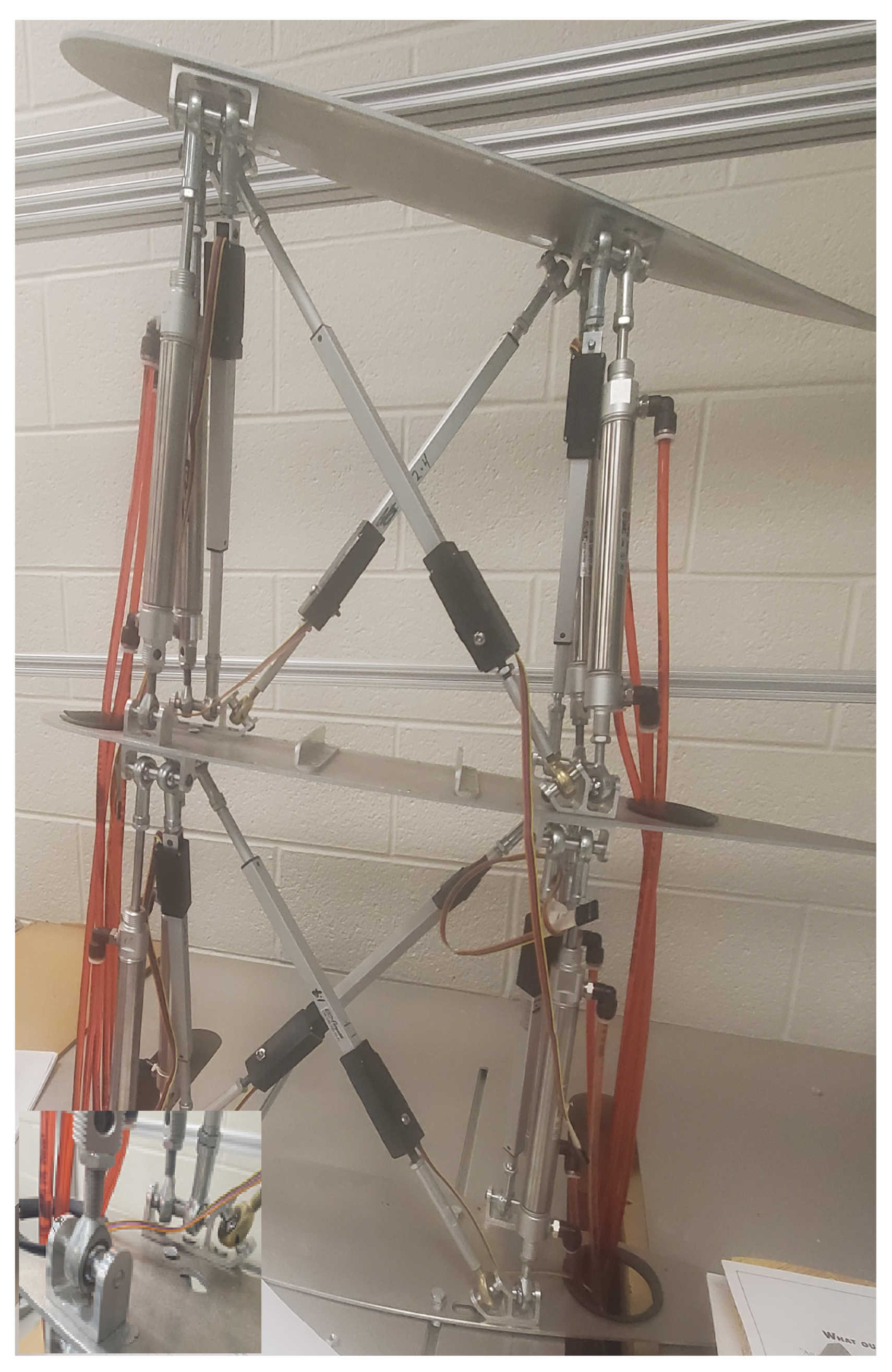
In their effort to implement multiple morphing parameters simultaneouly Finistauri et al. [
25], followed by Moosavian et al. [
26], have successfully applied the concept of a parallel robot manipulator to design a morphing wing. Their presented wing design is capable of spanwise, dihedral, and sweep morphing simultaneously in response to the flight condition requirements. Essentially, this designed morphing wing is modular in nature, and the optimum number of modules can be determined on the basis of a mission requirement. This modular characteristic of the wing phases out the cumbersome wing redesign tasks. Nevertheless, their work has remained limited due to the kinematic-based design of the wing, disregarding any structural and/or aerodynamic analysis. In an earlier work by the authors [
27], the free vibration analysis of this re-configurable modular morphing wing was presented, and the effects of topology, material properties, and spanwise expansion on the dynamic response of the system were explored. To the best of the authors’ knowledge, the combined effect of spanwise expansion and sweep on the dynamic response of a morphing wing has not been reported in the literature. The changes in modal frequencies caused by these two morphing parameters will lead to alteration in the aeroelastic characteristics of the wing. Therefore, the flutter might be associated with different mode shapes of the system occurring at a different airspeed. This could be beneficial in delaying flutter or devastating by causing flutter inception before the designed flutter speed. Furthermore, the dynamic behavior of individual constituent members defines the overall deformed shape of the wing. Consequently, the overall wing might exhibit a different pressure drag compared to the intended design. This change in drag could offset the possible advantage of fuel savings by the intended morphing wing design. Moreover, information on dynamic behavior of the constituent members will also be helpful in finding any undesired vibration that could lead to nuance to the passenger, and in determining the possible members’ failures. Hence, it is deemed imperative to include the effect of sweep as a logical next step of the authors’ recent work [
27].
The objective of the present paper is multifold.
First, to perform a modal analysis of the re-configurable modular morphing wing by using two modules in un-morphed configuration.
Then, to investigate the natural frequencies and modes of the morphing wing under the morphing effects of various sweep angles and spanwise expansions.
Finally, to execute the statistical analysis by using the Taguchi method to determine the most effective morphing factor/parameter governing the natural frequencies of the morphing wing.
4. FEM-Based Numerical Simulation and Discussion
As mentioned earlier in this paper, the morphing wing studied here consists of two modules. Moreover, there are 26 beams in total. The diameter of each beam in its un-morphed (benchmark) configuration is 0.0254 m (1 in). The distance between two wing ribs, i.e., the un-morphed module length, is 0.254 m (10 in) (refer to
Figure 2). Mechanical properties of structural beams (active and passive) are given in
Table 1.
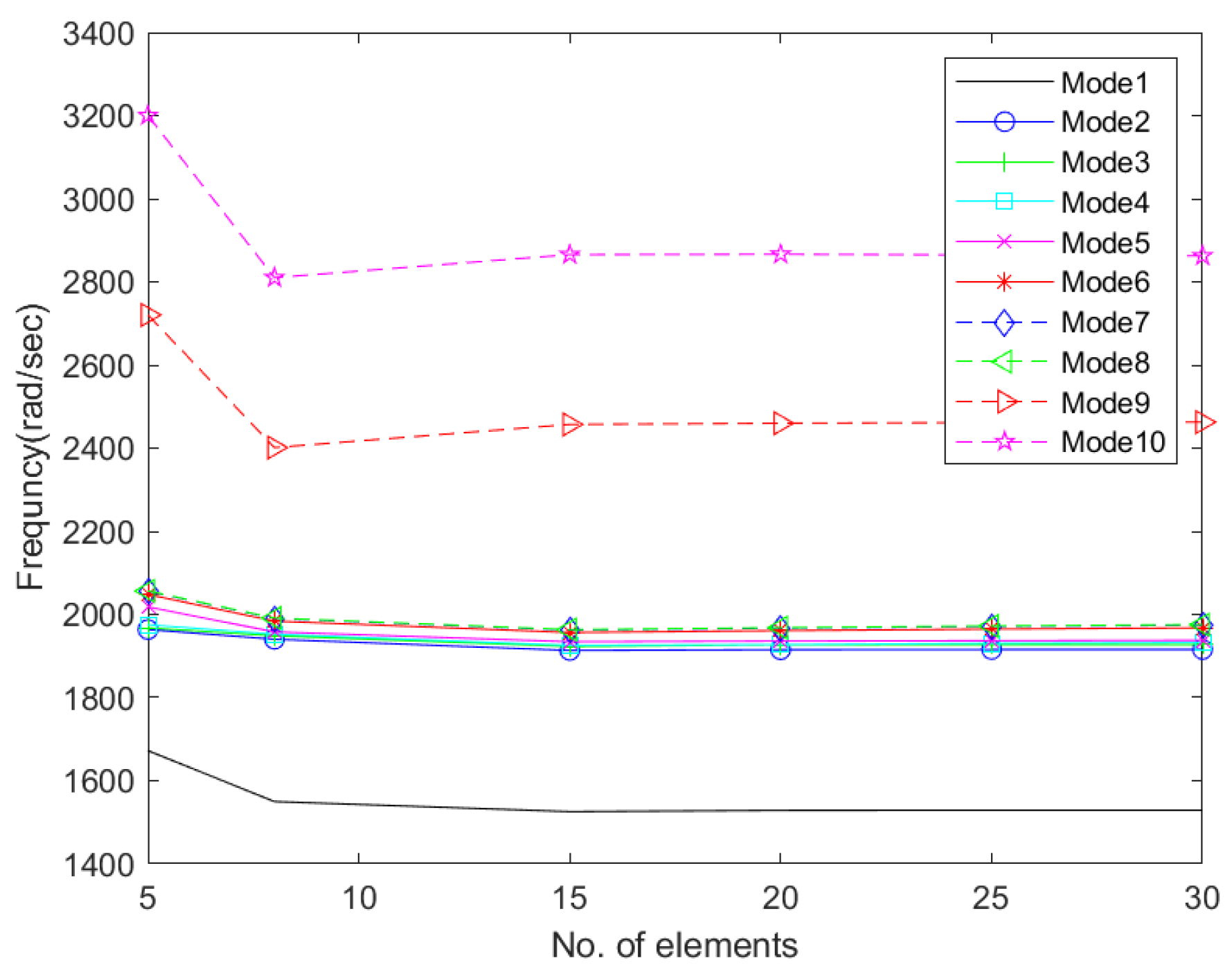
Based on a comprehensive convergence test, it is noted that 30 elements per beam are sufficient for the converged solution (see
Figure 6). Therefore, in the subsequent simulations, all 8 load-bearing beams in each module are discretized into 30 Timoshenko elements with 6 DOF per node. However, for the 5 beams, representing each wing rib, 4 Timoshenko elements are deemed sufficient.
Modal analysis, based on the conventional finite element methodology (FEM), is performed and the frequency results are compared with those obtained from the dynamic stiffness method (DSM). Details of the validation results are given in the authors’ earlier publication and are omitted here for the sake of brevity [
27].
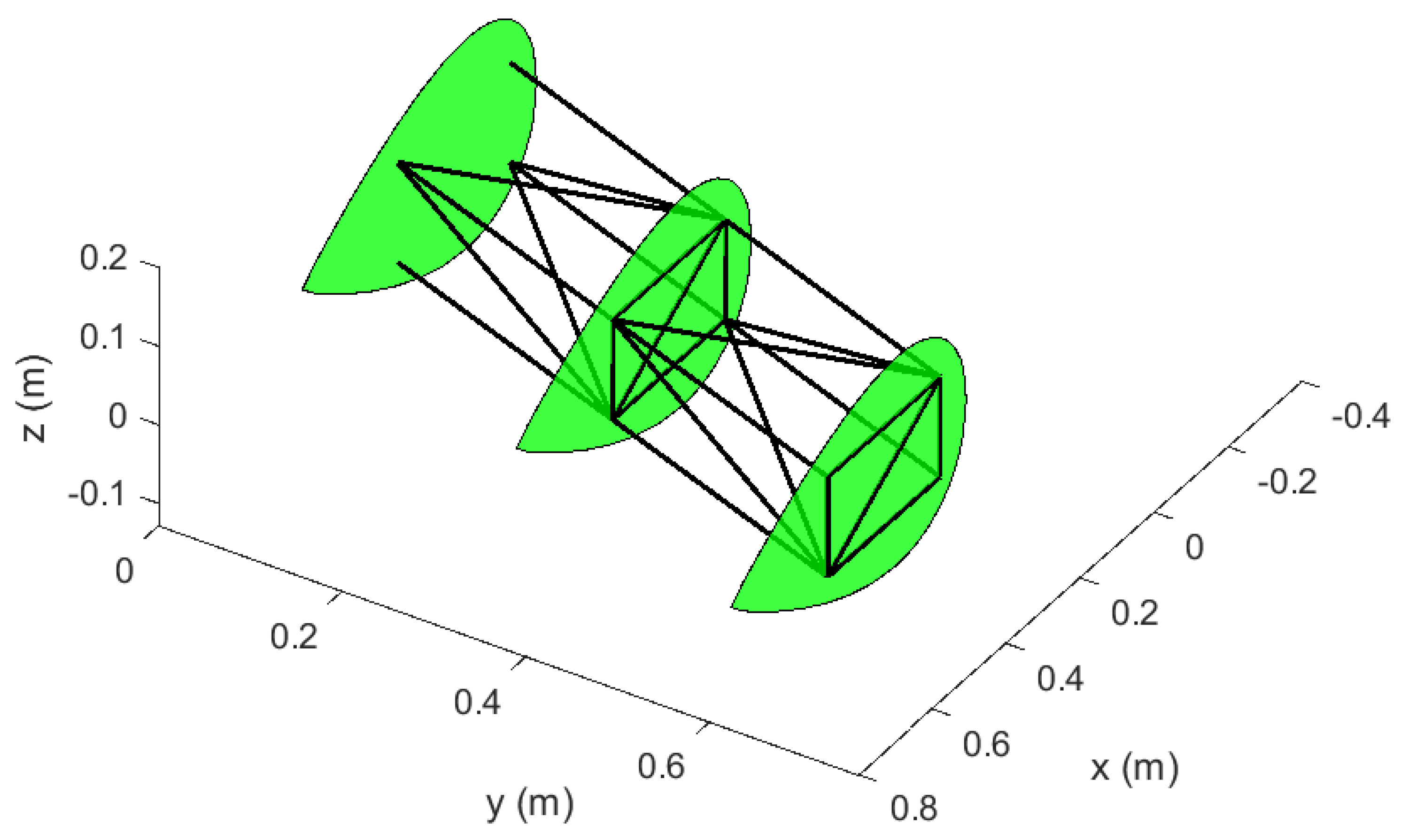
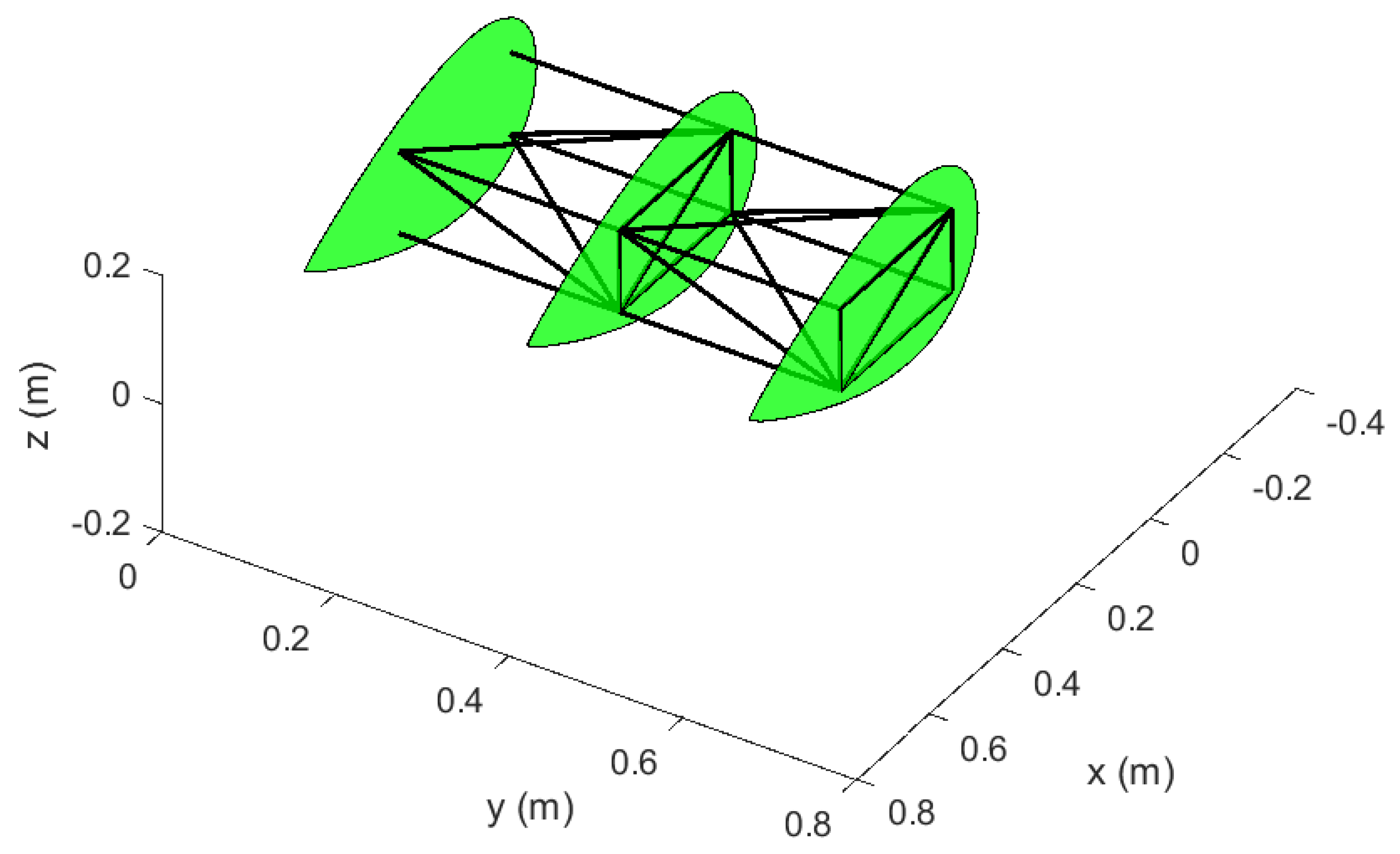
First, the un-morphed wing is simulated as the benchmark case for the modal analysis. With the
x axis along the aircraft longitudinal direction and the
y axis along the wing span direction, the un-morphed wing configuration is shown in
Figure 7. Airfoils have been added here for visual ease. The computed first 10 natural frequencies of the benchmark case are presented in
Table 2.
In the ensuing paragraphs, modal analyses of the wing in morphed configurations are presented. Various combinations of sweep and spanwise expansion have been applied, and their effects on the free vibration of the wing are investigated. As mentioned earlier in this paper, for every expansion case of the morphing wing, the diameter (therefore, area and moment of inertia) of each structural beam was calculated by keeping its corresponding mass constant.
The two morphing parameters/factors, i.e., sweep and spanwise expansion, along with their respective 5 levels applied in this work, are given in
Table 3.
For a complete design of experiments (DOE), a total of
simulations are needed to investigate the effects of various combinations of the two factors’ levels. The Taguchi orthogonal array (L25), for this DOE, is presented in
Table 4 [
32,
33,
34].
The resulting first 10 natural frequencies, corresponding to the 25 simultionss, are presented in
Table 5, and their corresponding mode shapes have been extracted. Simulation 11, in essence, represents the benchmark case. By comparison with the natural frequencies of the original/un-morphed configuration (see
Table 2), it is found that the first 5 natural frequencies diminish in their values. However, the next 5 frequencies increase compared to their benchmark case’s counterparts.
By changing the sweep, while keeping the span length the same, the configuration of the wing is altered in terms of mass and stiffness distribution. The increase in the sixth and higher natural frequencies could be attributed to the above-stated fact that the morphed wing is in fact a different configuration. This change in configuration, indeed, leads to different mode shapes as compared to their corresponding benchmark case for modes higher than 5.
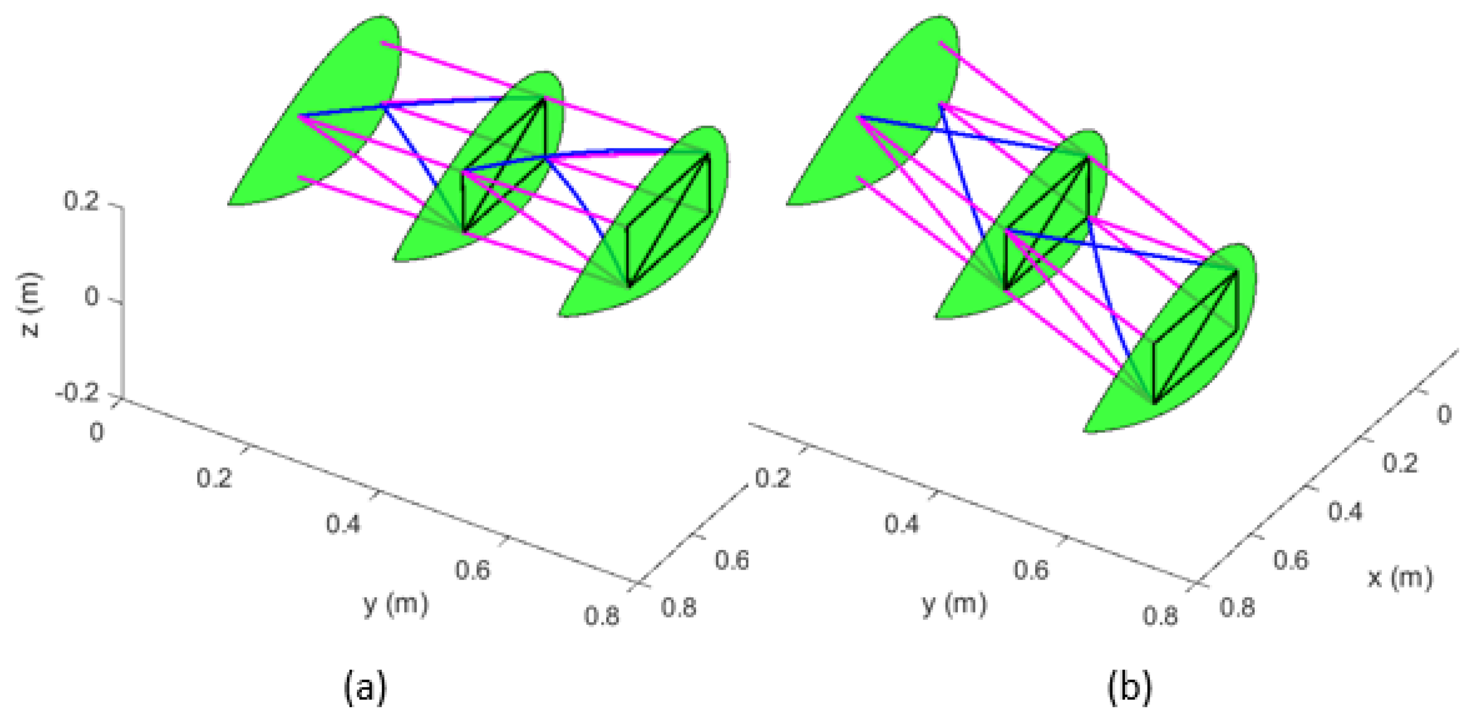
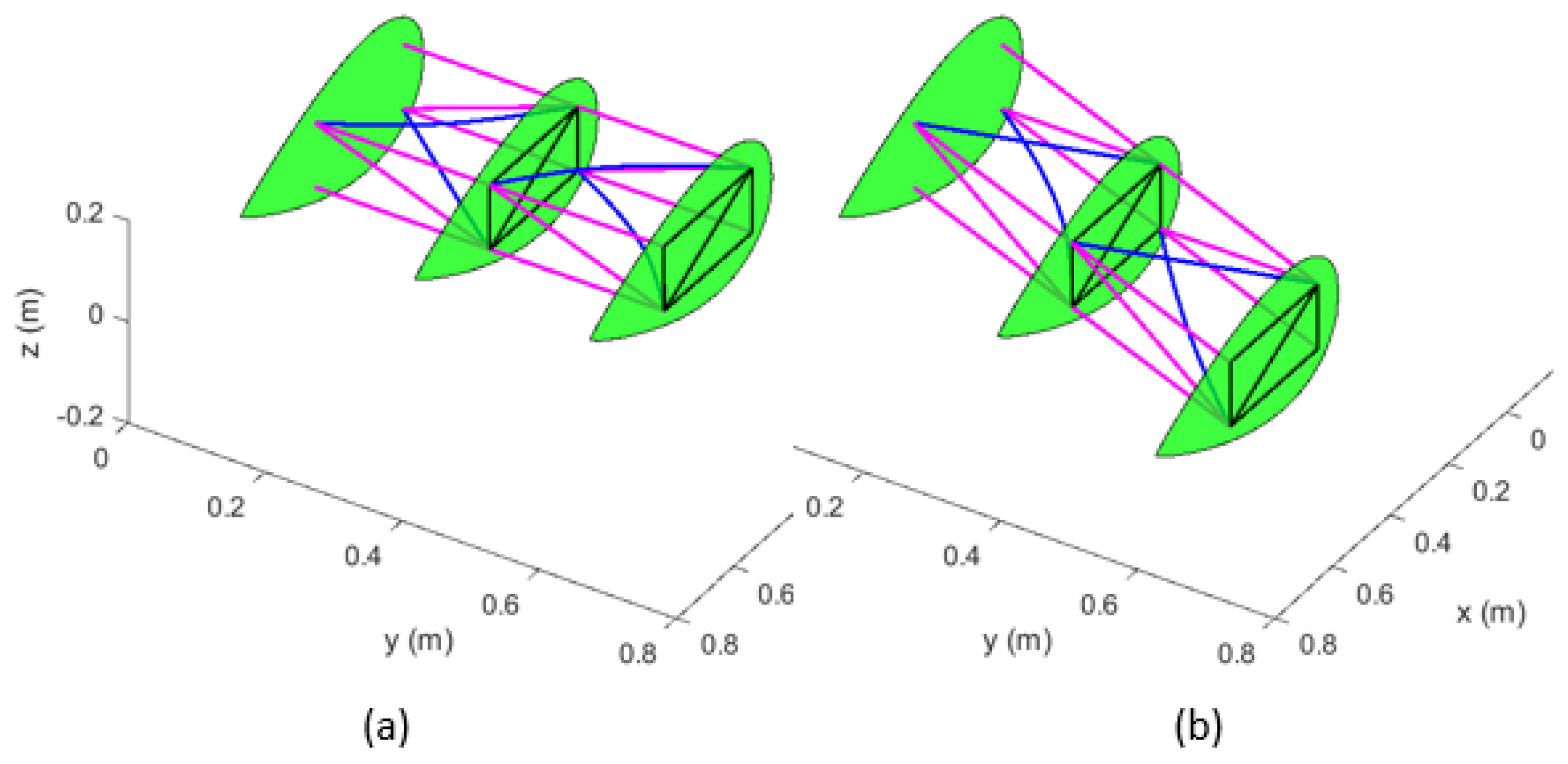
The undeformed wing in morphed configuration for simulation 25 is shown in
Figure 8. For illustration purposes, only the first 10 mode shapes for simulation 25, involving sweep of
and a spanwise expansion of
, are extracted and presented in
Figure 9,
Figure 10,
Figure 11,
Figure 12,
Figure 13,
Figure 14,
Figure 15,
Figure 16,
Figure 17 and
Figure 18. For the sake of comparison, the un-morphed wing’s mode shapes are also presented in
Figure 9,
Figure 10,
Figure 11,
Figure 12,
Figure 13,
Figure 14,
Figure 15,
Figure 16,
Figure 17 and
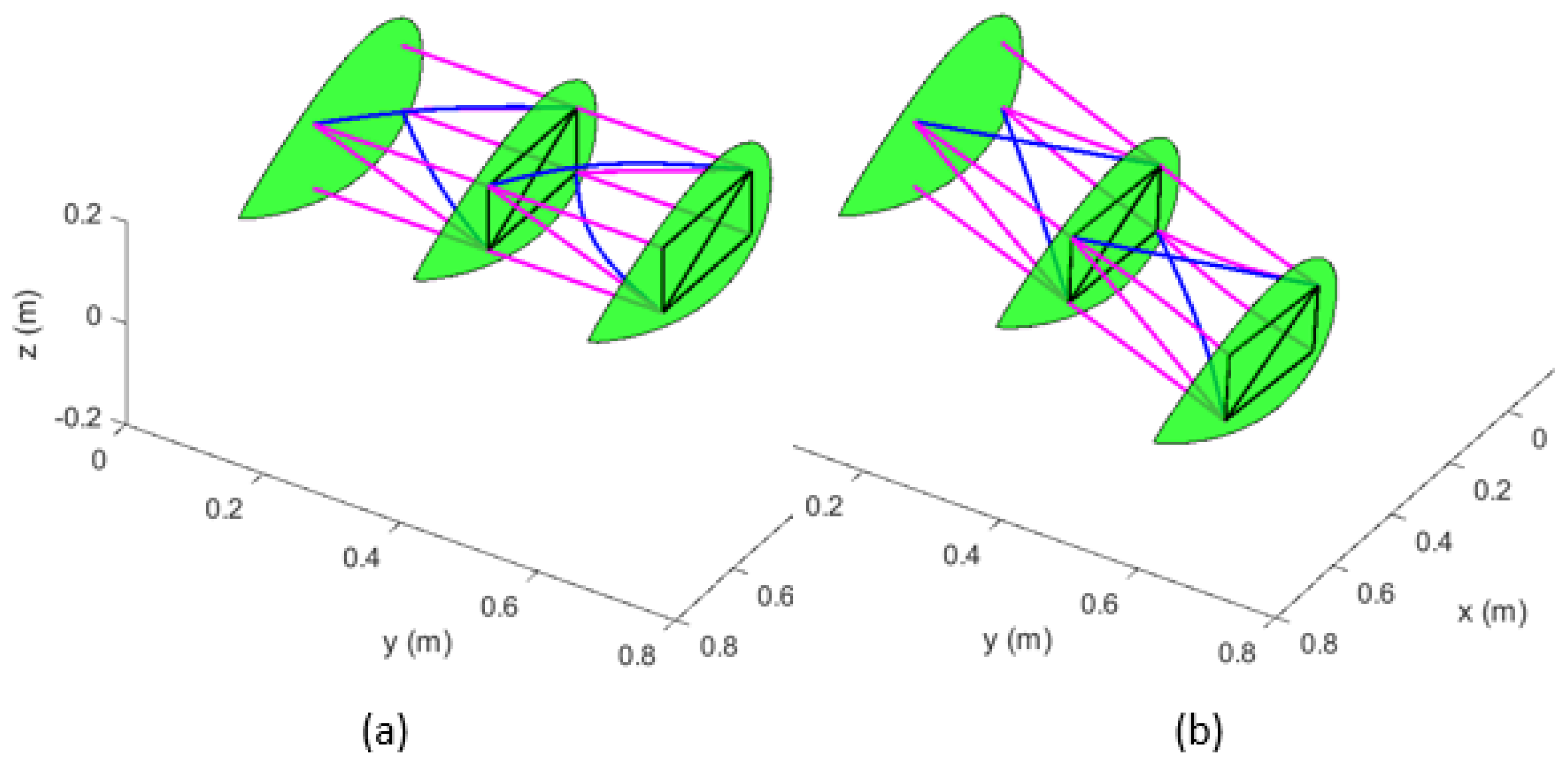
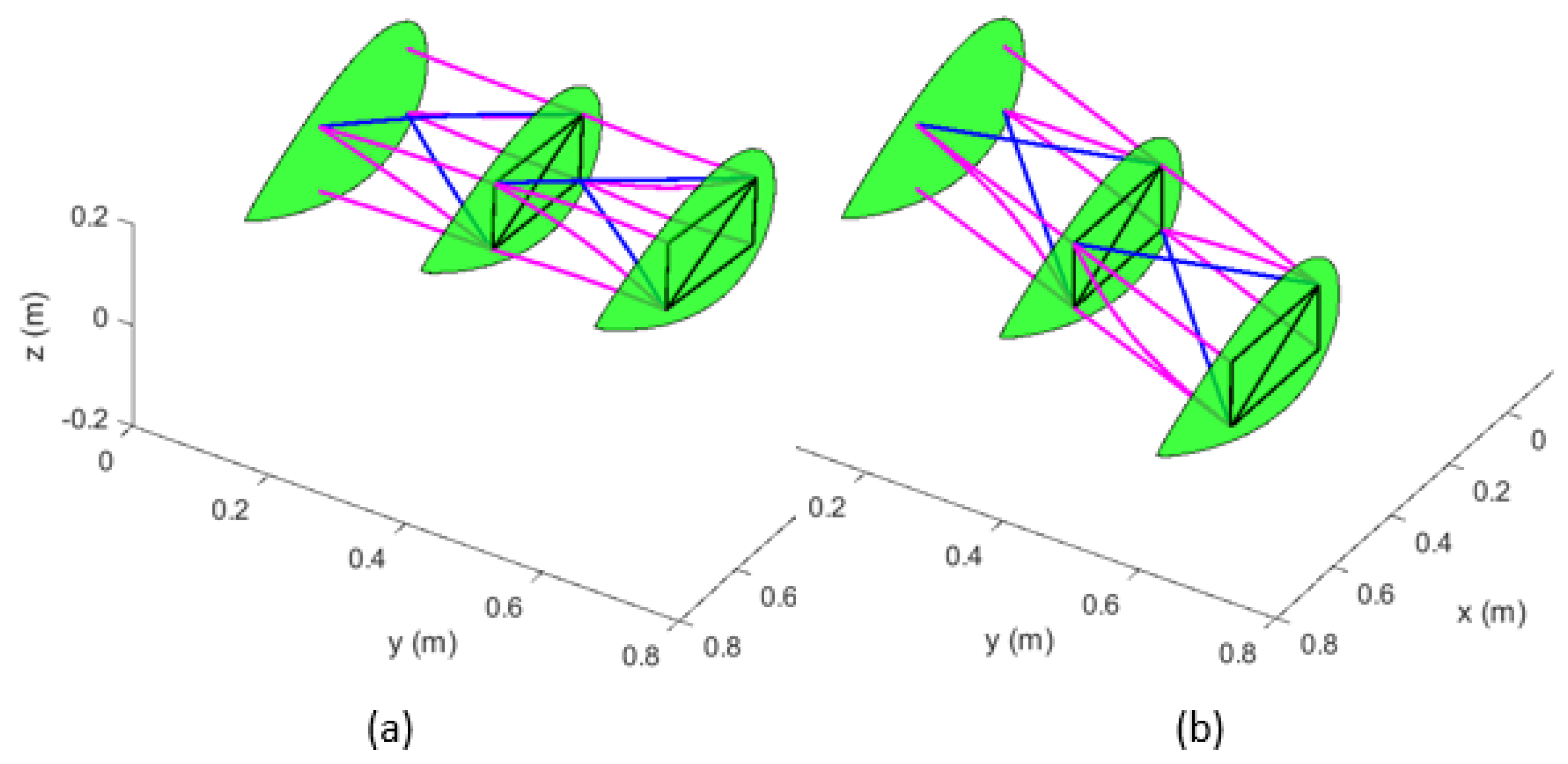
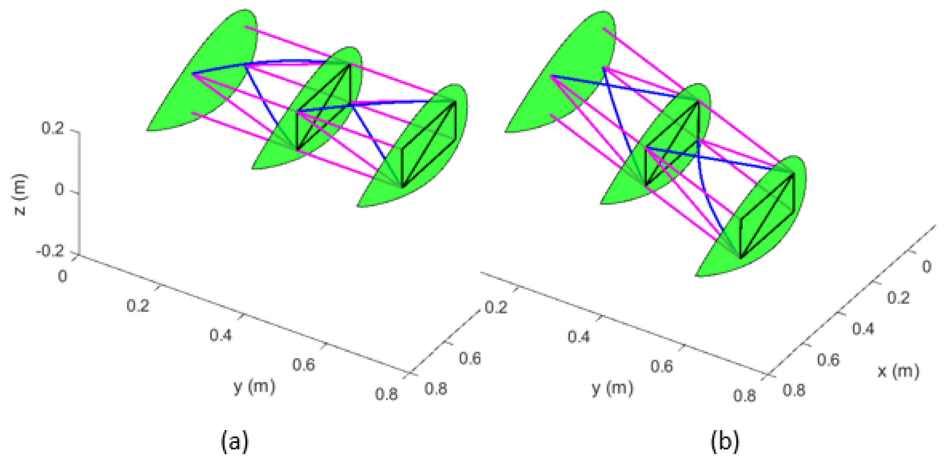
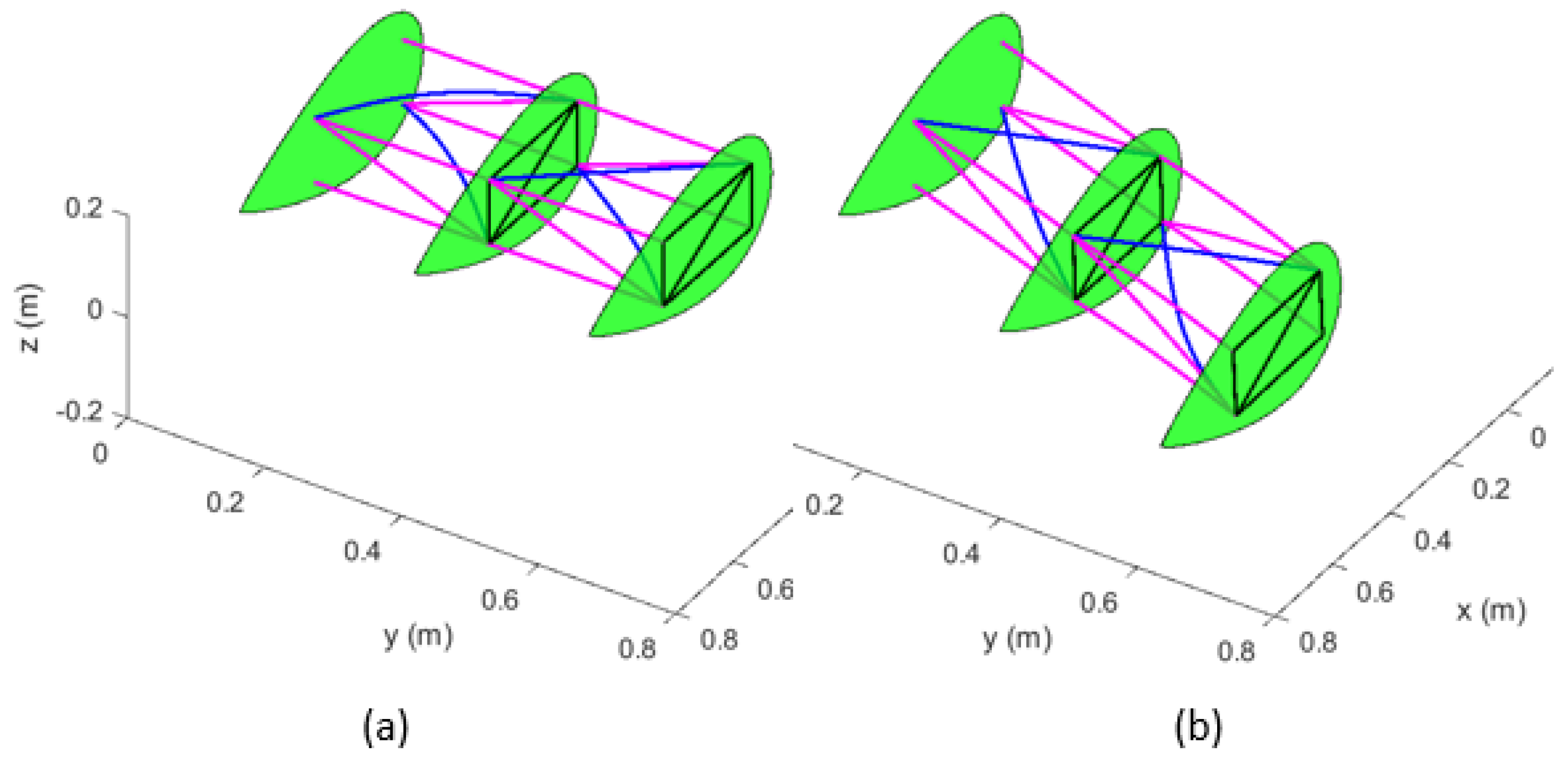
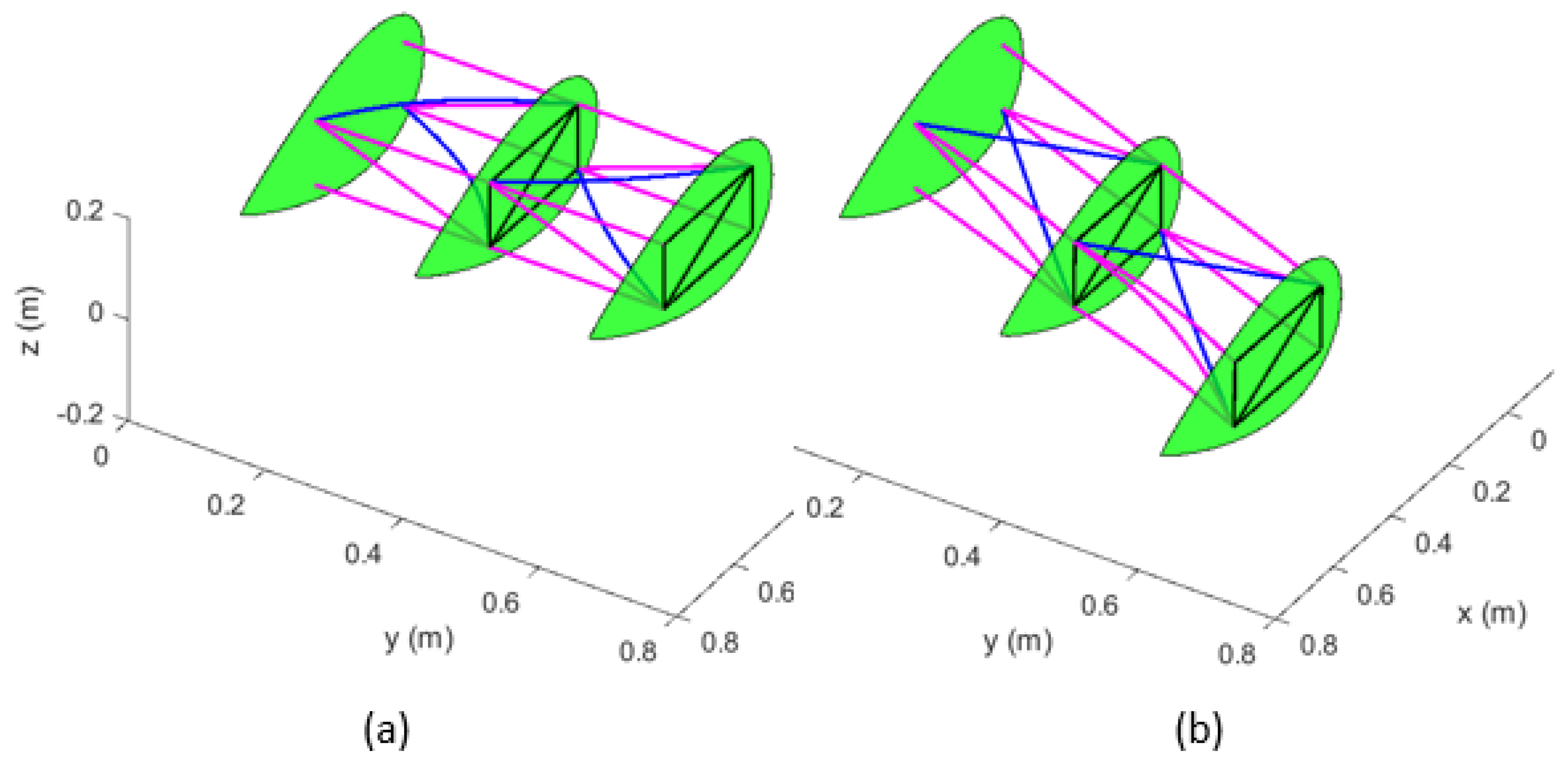
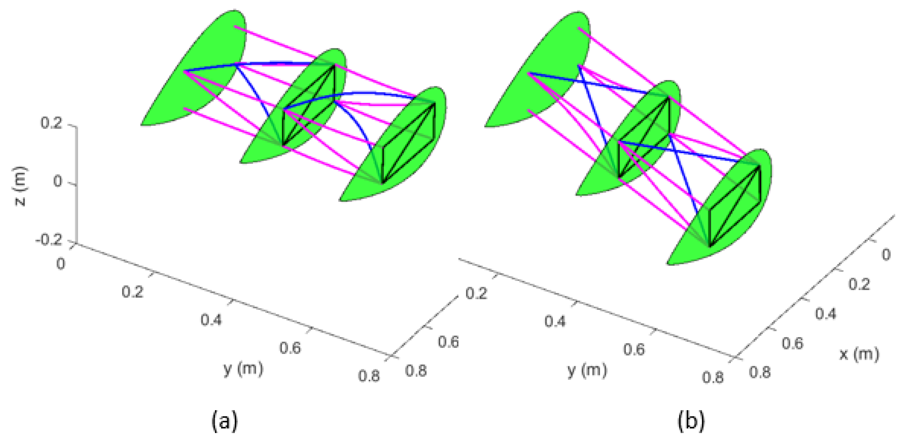
Figure 18. The purpose of these plots is to showcase how the various internal constituent members respond to morphing in terms of their flexural or axial motion, if any. This information is necessary in order to tailor the overall stiffness of the wing required for aircraft performance against drag reduction and hazard assessment of the wing. It is clear from these plots that the constituent structural beams undergo local flexural motion, individually or in combination, without producing considerable in-plane or out-of-plane motion of the entire wing. This can be attributed to the inclusion of the spherical joints at the beam end connections. These joints do not transfer the bending of the beams and resist only the axial displacement to the ribs. It is clear from these plots that different beams exhibit flexural motion for the morphed case as compared to the un-morphed case. For example, in mode 1, the upper diagonal beam of module 1 exhibits distinct flexural motion in the un-morphed configuration. However, in the morphed configuration, the flexural motion of the lower diagonal beam of module 2 is clearly visible. Also, in mode 6, it is found that all upper and lower diagonal beams in the un-morphed configuration exhibit noticeable flexural motion. On the contrary, the corresponding morphed configuration presents no flexural motion of diagonal beams. Similar observations can be made in other modes as well. Moreover, it is observed from these figures that in both un-morphed and morphed configurations, the first 5 mode shapes exhibit flexural motion of the top and bottom diagonal (active) members in each module. However, unlike the un-morphed configurations, flexural motion of the upstream and downstream diagonal (active) members become evident for modes 6 and higher. Therefore, it can be deduced that new modes become visible after mode 5 during sweep morphing. The increase in natural frequencies of mode 5 and higher in sweep morphing, as noticed above, can be attributed to this observation.
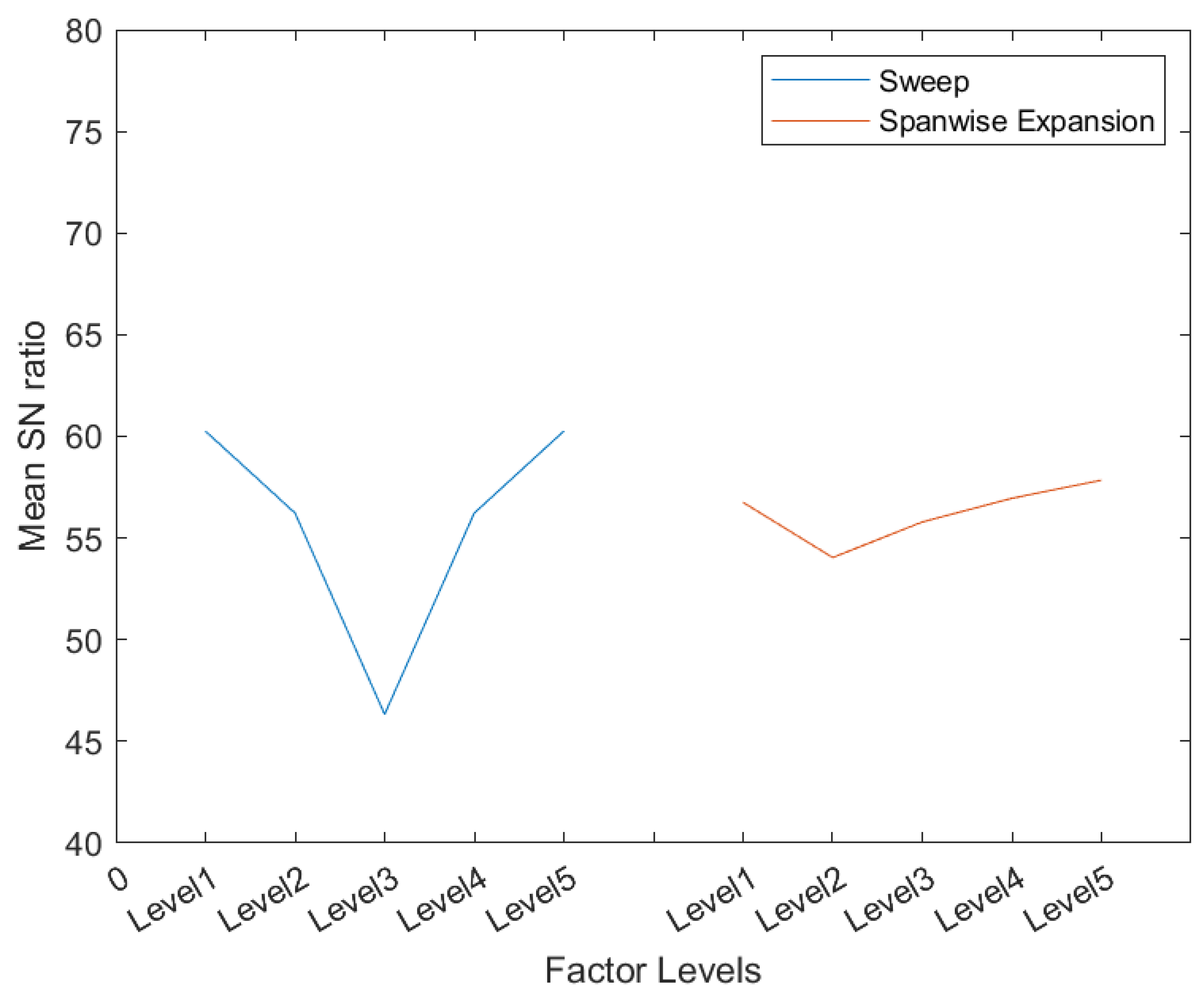
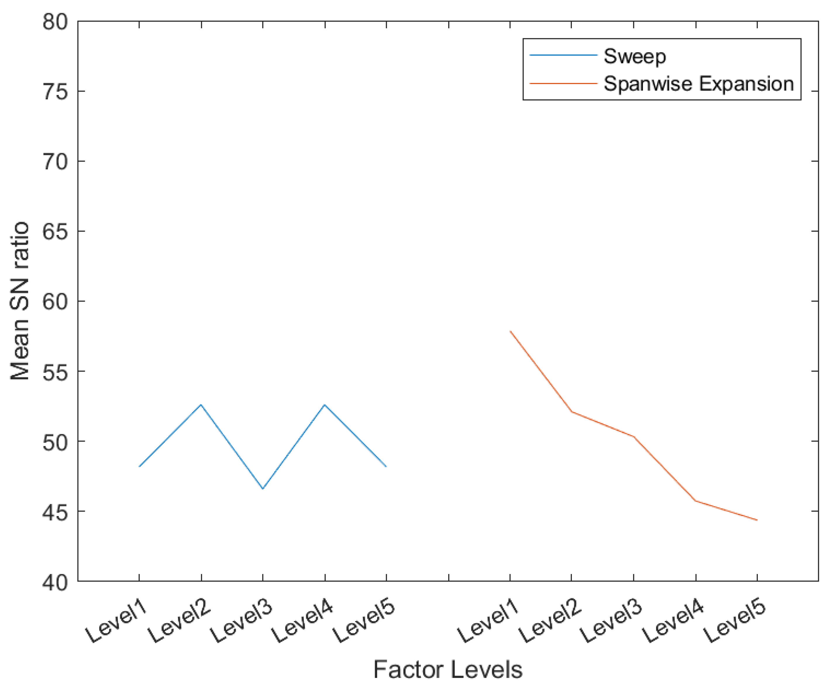
Signal-to-noise ratios (SN), as per the Taguchi methodology, are computed for all 25 simulations to investigate the effect of factors and their levels on changing the natural frequencies of the system. This change in frequencies is based on their difference from the corresponding un-morphed wing’s natural frequencies. The maximum is better methodology is adopted to compute the SN ratio [
32,
33,
34]. By following the Taguchi technique, the mean SN ratios of the two factors’ levels for the second mode, shifted along abscissa for visual discernability, are given in
Figure 19. This figure clearly reveals that sweep is the most effective morphing factor in controlling the natural frequencies of the wing, followed by the spanwise expansion. This indicates that the sweep morphing, which essentially changes the aspect ratio of the wing, also contributes to changing the stiffness of the system more as compared to spanwise expansion. It is also observed that expanding the wing in the spanwise direction at any non-zero sweep angle results in a high rate of decrease in frequencies as compared to sweep morphing for modes 6 and up. Consequently, it is found that spanwise expansion is the most effective parameter for modes 6 and higher (see
Figure 20 for mode 8). Therefore, it is concluded that sweep morphing leads to new stiffer modes in terms of flexural motion of the upstream and downstream diagonal (active) beams for mode 6 and higher. However, spanwise expansion decreases these newly generated modes with a higher rate as compared to mode 5 and lower, which are related to the vibration of upper and lower diagonal (active) beams of each module.
5. Conclusions
By offering a high lift-to-drag ratio, improved aerodynamic performance, and enhancement in maneuverability and flight envelope, the morphing wing aircraft can lead to considerable fuel efficiency. Therefore, the green aircraft concept is logically linked to the future development of a morphing wing. Contrary to these leverages, a cost is associated with a variable-shape wing in terms of increased weight, complexities of the system, control system, and aeroelastic characteristics. Therefore, an optimum solution is always imperative for these conflicting parameters to offset the associated penalties. Dynamic characterization of a morphing wing is the preliminary step required for this optimization. Therefore, a detailed investigation of the dynamic characteristics of the morphing wing must be performed and comprehended. In this paper, the free vibration of a special re-configurable modular morphing wing design, developed in-house at Toronto Metropolitan University, has been studied. Despite a truss-type configuration, it is shown here that structural members exhibit bending; therefore, truss element analysis is evidently a non-conservative approach. By designing an experimental procedure, under the combined effect of varying sweep and spanwise expansion, it is also shown that the studied topology leads to non-symmetrical bending; vertical bending (flapping) is more than higher in amplitude compared to in-plane bending (lead-lag) of the wing. This is in line with the common behavior of typical aircraft wings. No bending–twist coupling is obvious in this configuration for the studied first 10 modes. It is evident that sweep, due to its underlying effect of changing the wing’s aspect ratio, governs the natural frequencies of the morphing wing for modes 5 and lower. However, spanwise expansion remains dominant in terms of its effect on the natural frequencies for modes 6 and higher. It is also found that during the spanwise expansion morphing, the upper and lower diagonal constituent beam members exhibit distinct flexural motion as compared to the upstream and downstream members for modes 5 and lower. However, during the sweep morphing, upstream and downstream diagonal members’ flexural motion is dominant for modes 6 and higher. Therefore, it can be concluded that sweep morphing, due to its lesser contribution to the flapping motion of the wing, will offers higher stiffness against aeroelastic instability. In conclusion, more than 10 modes must be considered in order to obtain any subsequent reliable aeroelastic characteristics. Moreover, it can be concluded that the representation of a wing by one single beam or plate structural member does not provide a comprehensive picture of dynamic characteristics of athe morphing wing studied here.


