Article

Cross-Scale Light Absorption Properties of Surface Bionic Microstructures for Spacecraft Stealth

College of Astronautics, Nanjing University of Aeronautics and Astronautics, Nanjing 211106, China
*
Author to whom correspondence should be addressed.
Aerospace 2023, 10(6), 561; https://doi.org/10.3390/aerospace10060561
Submission received: 27 April 2023 / Revised: 30 May 2023 / Accepted: 13 June 2023 / Published: 15 June 2023
(This article belongs to the Section Aeronautics)

Abstract

:
To address the problem that the black coating for spacecraft optical stealth easily falls off, this study constructs a light-absorbing spacecraft surface based on a micro/nanostructure through imitating a natural light-trapping structure. In this paper, we first analyze the optical properties of a basic stealth structure with the finite difference time domain (FDTD) method and establish a mapping relationship between the light absorption rate of the basic stealth structure and its multiscale factors. Then, imitating the microstructural characteristics of the blackened parts of butterfly wings, we design a multilayered and multiscale complex stealth structure to achieve the optical stealth characteristics of low reflection and high absorption of sunlight on the surface of the spacecraft. Simulation analysis shows that the bionic microstructure can be used to change the optical properties of the metal surface to a certain wavelength band; the complex stealth structure designed based on the butterfly wing can absorb 80.18% of visible light and reduce the overall brightness of the high-orbiting spacecraft by four orders of magnitude.

1. Introduction

The current detection threat faced by high-orbiting spacecraft mainly comes from ground-based optical systems. For space-based target detection, the available international means are ground-based or space-based radar and optical systems; among them, ground-based radar surveillance systems are limited by the detection distance, energy constraints and other conditions, making it difficult to observe high-orbiting spacecraft, while space-based systems are limited by power, observation direction and other conditions and are generally used to observe targets at lower altitudes than their altitude. Therefore, stealth research on high-orbiting spacecraft focuses on how to circumvent ground-based optical observations.
There are three main means of optical stealth for spacecraft: (1) configuration stealth, in which the probability of detection is reduced via reducing the optical cross section (OCS); (2) material stealth, in which the spacecraft is coated with light-absorbing coatings or has loaded light-absorbing materials installed; and (3) maneuvering stealth, in which reflection of sunlight in the observation direction is avoided through attitude adjustment. Among these, attitude maneuver stealth is related to the capabilities of the platform and has greater limitations. Current stealth mainly revolves around configuration and material stealth. In terms of configuration stealth, analogous to the shape design of a stealth aircraft, a prismatic smooth surface is used to reduce scattering characteristics. Zhu [1] proposed an optically stealthy spacecraft configuration that has an OCS peak of only 0.082 m2. Additionally, in terms of stealth materials, nanostructure-based metamaterial absorbers have been attracting enormous interest owing to their widespread applications in solar cells, thermal emitters and integrated photonic devices. Mehrabi [2] explored and implemented an ultra-broadband nanostructured metamaterial absorber (NMMA) whose average absorption reaches 96% in the wavelength range from 200–3000 nm (from ultraviolet to mid-infrared), and the minimal absorption is also above 90% in a continuous large operating spectrum ranging from 200–2800 nm. Naveed [3] presents a novel and ultrathin broadband metamaterial absorber composed of a hexagonal nano-ring-shaped fractal structure (FMA) which manifests more than 97% absorptivity for the operating wavelength from 820 to 2520 nm. Liu [4] proposed and numerically analyzed a polarization-independent, wide-angle and ultra-broadband absorber based on a multi-layer metasurface whose average absorption rates were more than 97.2% covering the broad wavelength of 400~6000 nm (from visible light to mid-infrared light). Wang [5] used graphene oxide to modify aluminum pigments, with a 49% reduction in brightness, a 23% reduction in visible light reflectance and a 58% reduction in gloss. Ding [6] proposed a broadband ultrathin visible absorber without photolithography, consisting of a multilayer dielectric and a metal film, with an absorption rate greater than 90% in all visible wavelength ranges. Rana [7] designed visible-light-absorbing metamaterials using tungsten, which had nearly 99% absorption in the 400–800 nm band. The two-dimensional metamaterial ultrawideband absorber proposed by Wu [8] achieved an average absorption of 97.8% in the wavelength range from 400 to 1500 nm. In addition, through increasing the number of metal–dielectric pairs in the unit structure and using both gold and iron, the improved absorber achieved an average absorption of 96.4% in the range from 400 to 2000 nm. Ghobadi [9] proposed an ultrabroadband absorber based on a metal–insulator–metal (MIM) structure with an average absorption of 94% in the range of 300 to 1000 nm. Ni [10] experimentally verified an ultrathin stealth cloak wrapped around an object, consisting of a hypersurface with a distributed phase shift 80 nm thick, which hid arbitrarily shaped three-dimensional objects wrapped within it through fully recovering the phase of the reflected light at the 730 nm wavelength. Hsu [11] proposed a novel hypersurface design for linearly polarized broadband stealth carpets in the visible wavelength range from 650 nm to 800 nm.
At present, the detection capability for high orbits reaches a brightness magnitude of 18, so high-orbit optical stealth requires a brightness magnitude higher than 18. The optical stealth configuration alone has difficulty achieving this requirement, and although stealth materials or coatings have good light-absorbing properties, at this stage, for the majority of organic polymers, the space irradiation environment adaptability is poor, and the coating easily peels or ages. In this paper, inspired by the light-absorbing structure of the butterfly wing surface trapping over 98% of light [12], the exposed surface of a spacecraft is directly laser etched or covered with a mask with a light-absorbing microstructure (hierarchical rib structures) to achieve low reflection and high absorption of visible light. The finite difference time domain (FDTD) method is used to analyze the light absorption characteristics of the mask prototype of the complex optical stealth structure imitating the butterfly wing, and the optical stealth model of a whole satellite in high orbit is constructed based on this method, realizing analysis of the cross-scale stealth characteristics from “microstructure-prototype-whole satellite”.

2. Spacecraft Optical Stealth Characteristics Modeling

2.1. OCS-Based Spacecraft Brightness Magnitude Modeling

In the study of the optical scattering characteristics of space targets, similar to the radar-wave-scattering characteristic parameter, radar cross section (RCS), the OCS is applied to characterize the optical scattering characteristics of space targets. Based on the OCS combined with the observation distance, the brightness magnitude of the space target can be deduced, and then, through comparing the brightness magnitude with the observation capability, the optical stealth performance of the spacecraft can be assessed.
The OCS of a space target is only related to the surface properties, geometric structure and size of the target, as well as to the sun vector and the observation vector, and the relationship of each is shown in Figure 1. The OCS can be calculated as Equation (1) [13]:
S o c s = k = 1 n ( 1 A b s ) f r ( θ i , θ r , φ ) cos θ i cos θ r d A k
where fr is the bidirectional reflectance distribution function (BRDF) of the surface element, which is a function describing the material properties of the surface; Abs is the light absorption rate of the surface element microstructure; dAk is the area of the kth surface element; θi is the incident zenith angle, that is, the angle between the sun vector and the normal vector N of the panel; θr is the observation zenith angle, that is, the angle between the observation vector and the normal vector N of the panel; and φ is the observation azimuth, that is, the angle between the projections I’ and D’ of the sun vector I and the observation vector D on surfel dA.
Equation (1) shows that the target spacecraft can be divided into n face elements. When the normal vector, sun vector, observation vector and material information (BRDF) of each face element are known, the overall OCS of the spacecraft can be accurately calculated, which is obtained through superposing the OCSs of n surfels. Obviously, the smaller the surfel is, the more accurate the calculated OCS.
The selection of the BRDF model of the surface element in the OCS calculation is the key. Here, the improved Phong model for the Fresnel reflection phenomenon is used, as shown in the following formula:
f r = ρ d cos θ i + ρ s cos α β cos a θ i exp [ b ( 1 cos β ) 1 / π ]
where ρd is the diffuse reflection coefficient of the material; ρs is the specular reflection coefficient of the material; α is the mirror index; cosθi is the modified diffuse reflection term, introduced to adjust the reflection intensity of the mirror surface; and β is the difference between the observation direction and the mirror reflection direction, in which the included angle β = min{π/2, β}. a > 0 is used to adjust the intensity of the Fresnel phenomenon, and b > 0 is used to adjust the rate of increase or decrease of the specular component. The above model parameters for commonly used spacecraft surface materials [13] are shown in Table 1.
Combining Equations (1) and (2), the overall optical cross-sectional area Socs of the spacecraft can be calculated. However, to obtain the spacecraft brightness magnitude, a conversion is also needed. Here, the apparent magnitude is calculated, and the sun is used as a reference. The apparent magnitude of the sun is −26.74. After obtaining Socs, the apparent magnitude is:
m = 26.74 2.5 lg ( S o c s 4 π R 2 )
where R is the distance between the observation point and the space target. As shown in Equation (3), the larger the apparent magnitude is, the darker the target; the smaller the magnitude is, the brighter the target. The apparent magnitude is hereinafter referred to as the magnitude.

2.2. Spacecraft OCS Calculation Based on Z-Buffer Graphic Blanking

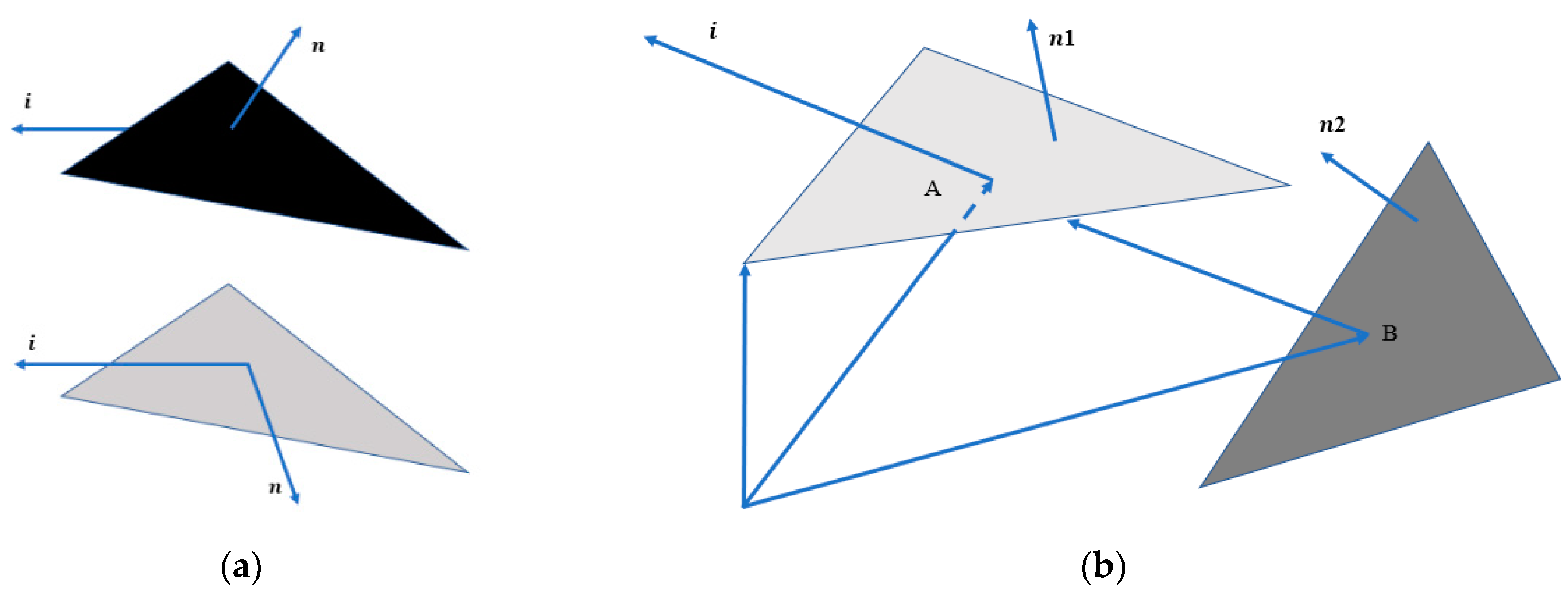
It can be seen from the above that the OCS calculation for the surface elements is the key to determining the magnitude of the spacecraft. However, due to the complex surface structure and illumination of the spacecraft, after surfel division is performed, it is necessary to judge the occlusion of the surfels. The occluded surfels are invalid surfels and should be eliminated in the calculation. The occlusion here includes both self- and mutual occlusion. Self-occlusion determines whether the panel is illuminated by sunlight, as shown in Figure 2a. In Figure 2, i is the incident sun vector and n, n1 and n2 are the normal vectors of the panels. Self-occlusion judgment is relatively simple, and the vector judgment method is used. Mutual occlusion means whether face element A is occluded by face element B, as in Figure 2b.
As seen from the figure, the mutual occlusion situation is complex, and this paper introduces the Z-buffer algorithm [14], a computer graphics blanking algorithm, to make the determination.
The Z-buffer algorithm is used to make the mutual occlusion judgment, and its schematic diagram is shown in Figure 3.
As shown in Figure 3, the xoy plane is the projection plane, and the z-axis is the viewing direction. Pass through any pixel point P(x, y) on the screen to make a ray parallel to the z-axis, and intersect the surface of the object at points P1 and P2. Then, the Z-buffer algorithm compares the z values of P1 and P2 and stores the largest z value. Obviously, the information of P1 is displayed on the screen as P(x, y). Because the surface of the satellite is complex and the materials are not consistent, this paper improves the traditional Z-buffer algorithm and stores the material information of the bins in the buffer to facilitate subsequent processing and calculation.
Apart from the Z-buffer algorithm, there are also other commonly used algorithms such as the painter algorithm, but since it cannot handle intersecting facets, the Z-buffer algorithm, which is a simple and easy-to-implement algorithm, is used in this paper.
Figure 4 shows the steps of the spacecraft OCS calculation based on Z-buffer graphic blanking, including 3D model surfel division, surfel information acquisition, sun vector acquisition, valid surfel judgment and surfel OCS stacking.
(1)
Spacecraft surface element classification: First, a 3D model with spacecraft surface details and element division of the surface is obtained using 3dmax, the material information of each surface element is confirmed and then, the modified and perfect spacecraft model is exported in OBJ format.
(2)
Spacecraft OCS 3D reconstruction: A program is written to read the OBJ format file, which includes the numbers of all surface elements and the coordinates of the three corresponding vertices; the surface element index is adopted to reconstruct the spacecraft model.
(3)
Spacecraft sun vector acquisition: Through using the spacecraft orbit information, the solar vector information in the orbital system can be calculated. In this paper, the spacecraft is stable along three axes with respect to the ground, i.e., the coordinates of this system coincide with the coordinates of the orbital system, so the solar vector in the orbital system is also the solar vector in this system. If attitude maneuvers are available, then the orbital solar vector can be easily projected onto the present system by means of the attitude matrix.
(4)
Effective surface element determination: This is the core step of the spacecraft OCS calculation. Based on the occlusion situation analyzed earlier, the valid face elements are marked based on the vector algorithm and the Z-buffer algorithm, which perform self-occlusion and mutual occlusion checks of the face elements, respectively.
(5)
Whole-star OCS calculation: Combining the BRDF model with the light absorption characteristics of the surface microstructure, the OCS of each effective face element is calculated and the whole-star OCS is obtained via accumulation.

3. Optical Stealth Design Based on Bionic Microstructured Surfaces

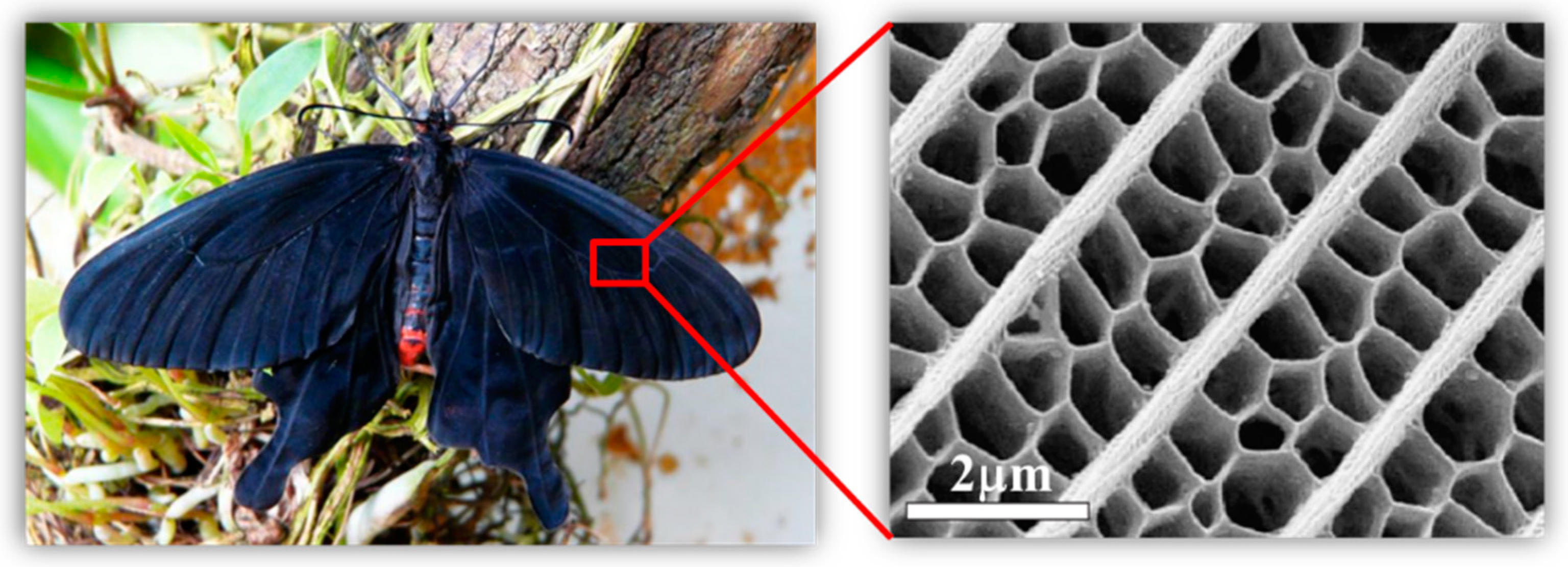
As seen from Equation (1), the greater the light absorption rate Abs of the surface element microstructure, the smaller the OCS of the spacecraft, i.e., the better the optical stealth effect. Therefore, if a suitable light-absorbing surface microstructure can be designed, then light absorption and thus stealth can be achieved without coatings. In fact, this situation is very common in nature, such as for the great blue banded butterfly Morpho menelaus terrestris [15,16,17,18,19,20] (e.g., Figure 5 left) and birds of paradise, whose wings or feather surfaces are mostly multilayered multilevel micro/nanostructures consisting of groove arrays, irregular raised arrays or irregular pore arrays (Figure 5 right), which have low reflection and high absorption properties for visible light and are therefore also called “photon traps”, which cause the surface of an object to appear visually black.
The photonic traps consist mainly of groove arrays, bump arrays and hole arrays, and the 3D modeled microstructures are shown in Figure 6.
For the above configurations, analysis of the optical properties corresponding to the microstructures can be performed through applying the finite difference time domain method [21] (FDTD) to obtain the Abs parameters. The microstructure models were built in the FDTD Solutions software, the incident light wavelength was set to 400–800 nm in the visible light range and the widely used metal Al was used as the material. The Abs values of the four configurations of “V-groove array”, “cylindrical array”, “pyramidal array” and “circular hole array” in Figure 6 were calculated at different wavelengths. The results are shown in Figure 7, Figure 8, Figure 9 and Figure 10. Multiscale optical characterization was also performed through adjusting key parameters of the microstructure, mainly the depth/height of the structure, the structural holes/diameters and the structural density (characterized by the spacing between adjacent units of the structure), to determine their effects on the light absorption rate. Of course, in the process of simulating any of the parameters, we will control the other parameters unchanged to better explain the influence of each parameter.
The above optical characteristics analysis results show the following:
(6)
The bionic microstructure has a good light absorption effect. Comparing the absorption parameters of the four configurations, it can be clearly seen that the V-groove array has the best light absorption effect. Figure 7a shows that the V-groove array can achieve more than 95% absorbance and achieve the stealth effect. The other microstructures can also achieve 80% absorbance through adjusting the parameters.
(7)
Microstructures with the same configuration can absorb specific wavelength bands through changing the structural parameters. Figure 7b shows that the V-groove array exhibits peak absorptivity for light in the 450–500 nm and 600 nm to 700 nm bands; Figure 10b shows that the hole array exhibits absorptivity peaks for light in the 700–800 nm band. That is, through changing the structural parameters, the surface of the object can show different colors.
(8)
Increasing the density of microstructures per unit area or increasing the height/depth of the structures can improve the light absorption properties. From Figure 7c, Figure 8c, Figure 9c and Figure 10c, it can be seen that when other scale factors are fixed, increasing the structural density can improve the absorption rate; Figure 7a, Figure 8a, Figure 9a and Figure 10a show that increasing the height or depth of the structure increases the light absorption rate.
The above simulation results can be used as a preliminary basis for the selection of composite microstructures, including the band of the absorption rate convex, the complexity of processing or bionic mapping.
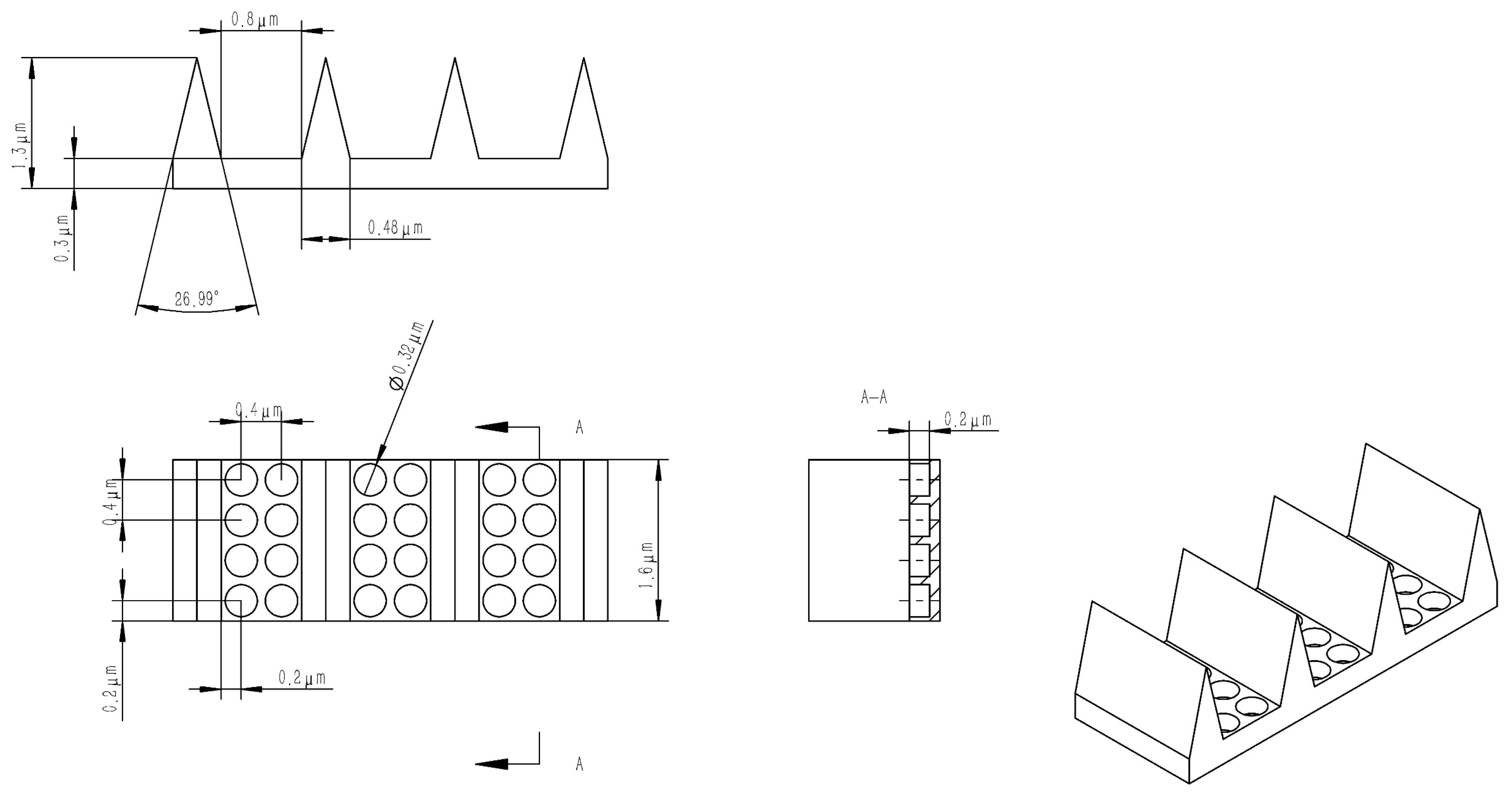
Based on the above analysis and inspired by the microstructured surface of the butterfly wing (Figure 5) with a groove–hole combination, this paper designs a composite optical stealth surface with a V-groove array as the main structure and a hole-like structure in the groove gaps as an additional structure, as shown in Figure 11.
The optical properties of the composite optical stealth surface are analyzed as follows:
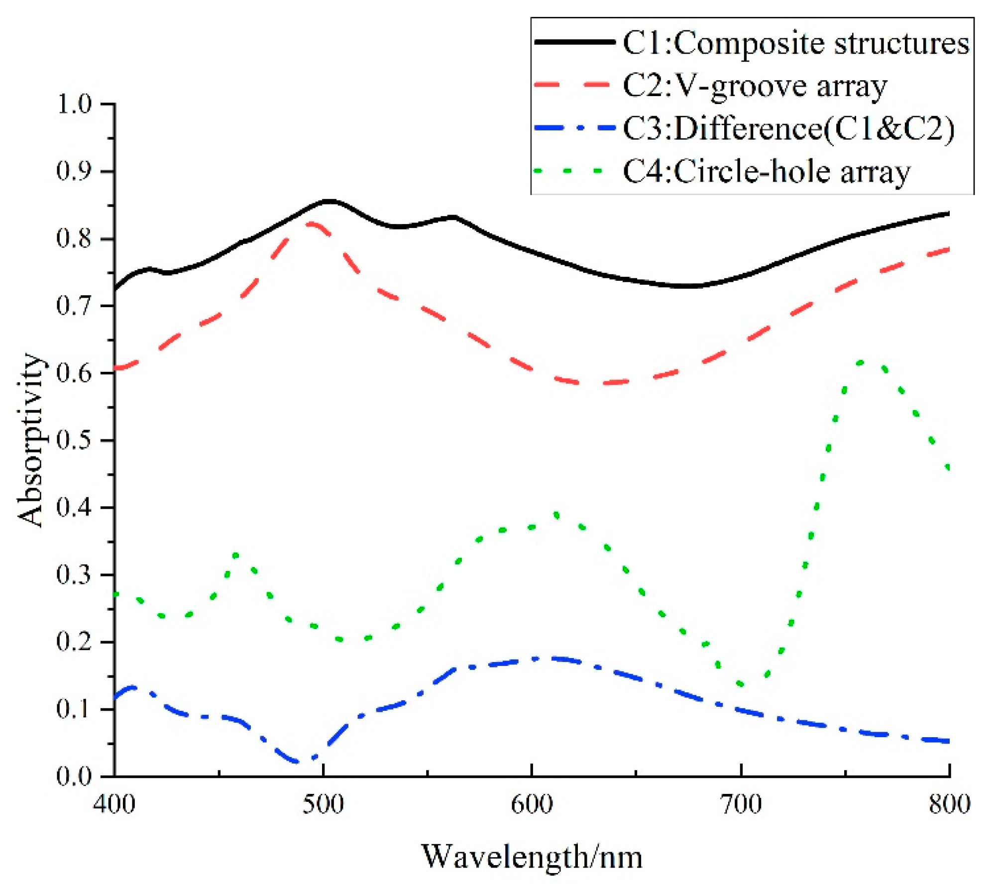
From Figure 12, comparing curves C1, C2 and C4, it is clear that the combination of the two micro/nanostructures results in a higher absorbance. It is worth noting that in the 500–70 nm band, the C2 curve is significantly concave, while the C4 absorbance curve of the corresponding hole-like structure is exactly convex. The curve for the combination of the two structures shows that the additional structure improves the low absorbance of the main structure in this band, and the composite structure can achieve an 80.18% absorption rate for visible light. The above conclusions show that the absorption rate can be optimized via combining different microstructures, but how the structures can be combined to achieve the optimum design will need to be further investigated.

4. Results and Discussion

4.1. Verification of the OCS Algorithm Based on Graphic Blanking with a Standard Body

In view of the analytical solution of the OCS of a simple geometry, this paper takes a Lambertian cylinder as the standard body, calculates the theoretical true value, and verifies the OCS algorithm based on graphic blanking proposed in this paper. The coordinate system XYZ shown in Figure 13a is established on the standard body, where OS in the figure is the light source vector, OD is the observation vector, the angle between OS and the y axis is η, the projection of OS on the XOZ plane coincides with the z axis, the angle between OD and the y axis is γ and the angle between the projection of OD on the XOZ plane and the z axis is β. If the hemispherical reflectance of the Lambertian cylinder is ρ, then its BRDF is ρ/π, and if the radius of the bottom surface of the cylinder is R, the height is L, and the standard solar irradiance is Esun, so the OCS expression of the Lambertian cylinder is [13]:
S o c s = { ρ 2 π R L sin η sin γ [ sin β + ( π β ) cos β ] 2 π + ρ 2 π R 2 cos η cos γ , cos η cos γ 0 ρ 2 π R L sin η sin γ [ sin β + ( π β ) cos β ] 2 π , cos η cos γ < 0
The faceted cylinder and the 3D faceted reconstruction are shown in red in Figure 13b. At the same time, to verify the effectiveness of the face element occlusion judgment and analyze the correctness of the results, a cylinder with radius R’ (R’ < R) is embedded inside the cylinder (shown in blue in Figure 13b); if the masking algorithm is correct, then this cylinder should have no effect on the OCS calculation results. Different test angles are taken, and the theoretical values are compared with the simulated numerical results.
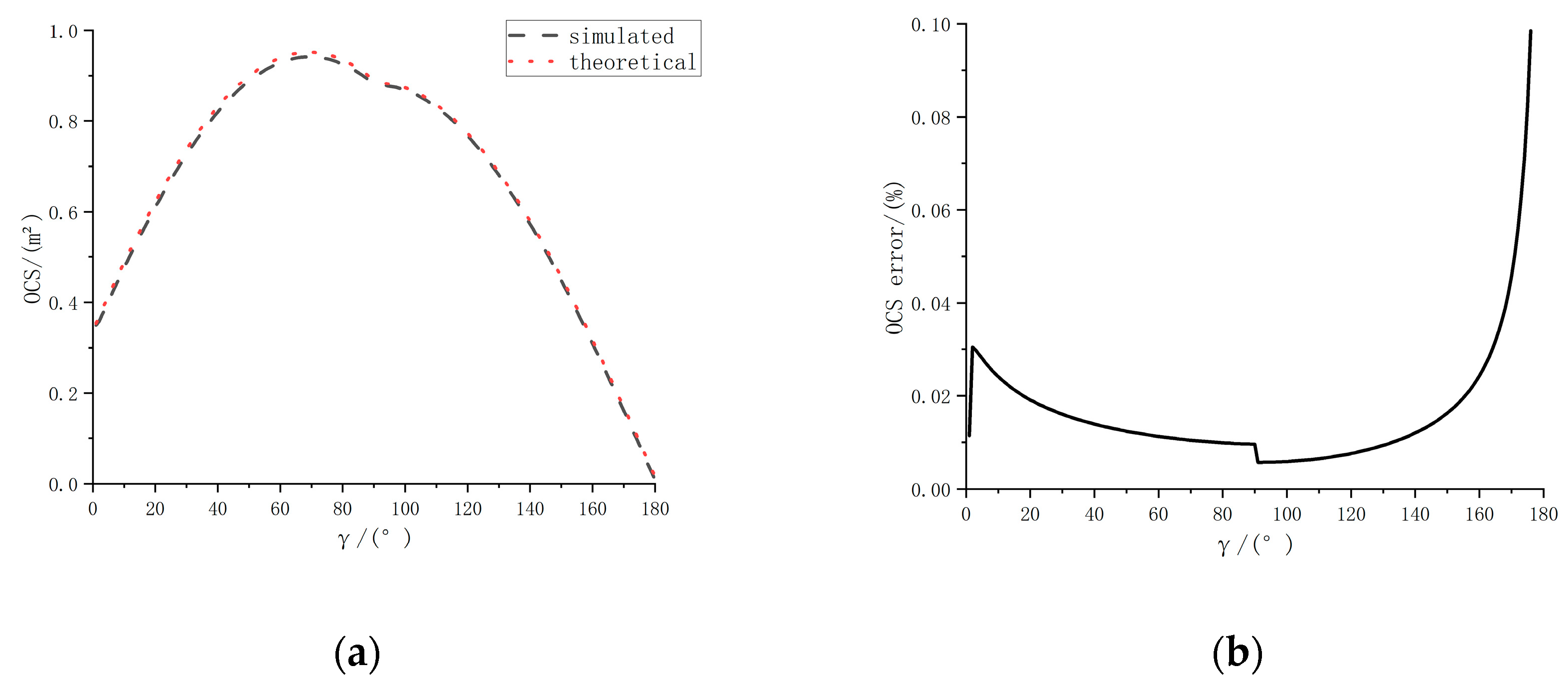
The simulation parameters are as follows: R = 1 m, L = 5 m, R’ = 0.8 m, L’ = 4 m, ρ = 0.5, β = 0°, η = 45°, the value range of γ is [0°, 180°] and the value interval is 1°, which means that the observation vector rotates from along the positive z−axis around the x−axis to along the negative z−axis by 1°/time. The OCS algorithm based on graphic blanking and the analytical method are used to calculate the OCS. The simulation results are shown in Figure 14a,b. The red curve in the figure is the analytical solution, which can be considered the true value, and the blue curve is the value simulated using the Z−buffer graphic blanking algorithm.
It can be seen from Figure 14a that the two algorithms are basically consistent. As seen from Figure 14b, the difference between the OCS based on graphic blanking and the theoretical value is no more than 0.10%. The results show that the algorithm is effective and has high accuracy.

4.2. Analysis of the Optical Stealth Characteristics of Spacecraft Using Biomimetic Microstructured Surfaces

In this paper, the U.S. “Misty” series of stealth spacecraft [22] is used as the reference object (Figure 15a), and the main body of the stealth spacecraft is designed with a combination of cones and cylinders (as shown in Figure 15b). To facilitate the analysis of the problem, the solar wing is not considered. Taking the forward direction of the spacecraft as the x−axis and the direction of the spacecraft cone tip pointing to the center of the earth as the z−axis, the y−axis is determined according to the right-hand rule, and the body coordinate system is established. The bionic microstructure is covered on the surface of the spacecraft, and the 3D model is reconstructed based on the OCS graphic blanking algorithm, as shown in Figure 15c, to verify its stealth characteristics.
The simulated orbit of the spacecraft is set to geosynchronous orbit (GEO), mainly because high-orbit observations are currently dominated by optics. The six values of the spacecraft orbit are ([42166257, 0, 0, 0, 0, 0]), which correspond to the semimajor axis, eccentricity, orbital inclination, ascending node right ascension, argument of perigee and true perigee, respectively. The observation vector coincides with the z−axis of the spacecraft system ([0, 0, 1]), that is, the subsatellite point of the observation station on the equator. Considering that the sun vector has periodic changes in one day, we set the simulation duration to 48 h and the step size to 0.5 h.
Figure 15 shows the observation results of the spacecraft before and after covering the micro/nanostructure on the surface obtained from the OCS calculation based on blanking, in which Figure 16a shows the comparison of the OCS simulation results and Figure 16b shows the comparison of the magnitude calculation results.
From the analysis of the simulation curves, the following can be seen:
(1)
After the stealth structure covering process is performed on the main surface of the spacecraft, the stealth effect is obvious: the darkest magnitude before stealth treatment is 14.6, whereas the darkest magnitude after stealth treatment is 18.71.
(2)
The stealth treatment of the spacecraft does not change its brightness pattern: when the angle between the sun vector and the observation vector is within ±5°, the smaller the angle is, the higher the brightness; when the angle between the sun vector and the observation vector exceeds 5°, the larger the angle is, the lower the brightness; and when the sun vector coincides with the x-axis, the spacecraft has the lowest brightness and the largest magnitude.

5. Conclusions

The enhancement of the stealth performance of a spacecraft plays an important role in its safe operation in orbit. This paper takes high-orbit spacecraft as the research object and proposes a calculation method for the optical stealth characteristics of high-orbit space satellites based on a computer graphics blanking method. In this method, the improved Phong model is used to describe the material of the satellite model, the Z-buffer algorithm is used to hide the satellite model and the optical stealth characteristics of the high-orbit satellite in space are analyzed in real time in combination with the satellite in-orbit operation status. The optical scattering characteristics algorithm has high accuracy, and the difference does not exceed 0.10% compared with the theoretical value. At the same time, starting from a bionic micro/nanostructure, this paper establishes an optical stealth micro/nanostructure library, analyzes the optical properties of the basic structure based on FDTD Solutions, summarizes the influence of the micro/nanostructure on the visible light absorption characteristics and imitates the black part on the surface of a butterfly wing. The micro/nanostructure realizes a bionic complex stealth structure design through the combination of basic structures, which can achieve an absorption rate of 80.18% in the visible light band, reduce the overall brightness of the spacecraft by four orders of magnitude and greatly improve the stealth performance of the spacecraft.

Author Contributions

Conceptualization, G.K.; methodology, Y.Q.; formal analysis, Y.Q. and X.C.; writing—original draft preparation, Y.Q.; writing—review and editing, J.W. All authors have read and agreed to the published version of the manuscript.

Funding

This research was funded by the Stable Support Project of the Science and Industry Bureau (HTKJ2019KL502002), Jiangsu Provincial Innovation and Entrepreneurship Talent Project (JSSCBS20210181), and the Open Project Program of Wuhan National Laboratory for Optoelectronics (2019WNLOKF011).

Data Availability Statement

Not applicable.

Conflicts of Interest

The authors declare no conflict of interest.

References

  1. Zhu, D.; Zhang, Z.; Zhao, C.; Liu, Y. A satellite configuration design for optical stealth. Aerosp. Control Appl. 2017, 43, 61–66. [Google Scholar]
  2. Mehrabi, S.; Bilal, R.; Naveed, M.; Ali, M. Ultra-broadband nanostructured metamaterial absorber based on stacked square-layers of TiN/TiO2. Opt. Mater. Express 2022, 12, 2199–2211. [Google Scholar] [CrossRef]
  3. Naveed, M.; Bilal, R.; Baqir, M.; Bashir, M.; Ali, M.; Rahim, A. Ultrawideband fractal metamaterial absorber made of nickel operating in the UV to IR spectrum. Opt. Mater. Express 2021, 29, 42911–42923. [Google Scholar] [CrossRef]
  4. Liu, J.; Chen, W.; Zheng, J.-C.; Chen, Y.-S.; Yang, C.-F. Wide-Angle Polarization-Independent Ultra-Broadband Absorber from Visible to Infrared. Nanomaterials 2020, 10, 27. [Google Scholar] [CrossRef] [Green Version]
  5. Wang, K.; Wang, C.; Yin, Y.; Chen, K. Modification of Alpigment with graphene for infrared/visual stealth compatiblefabric coating. J. Alloys Compd. 2017, 690, 741–748. [Google Scholar] [CrossRef]
  6. Ding, F.; Mo, L.; Zhu, J.; He, S. Lithography-free, broadband, omnidirectional, and polarization-insensitive thinoptical absorber. Appl. Phys. Lett. 2015, 106, 061108. [Google Scholar] [CrossRef]
  7. Rana, A.S.; Mehmood, M.Q.; Jeong, H.; Kim, I.; Rho, J. Tungsten-based ultrathin absorber for visible regime. Sci. Rep. 2018, 8, 2443. [Google Scholar] [CrossRef] [PubMed] [Green Version]
  8. Wu, D.; Liu, C.; Liu, Y.; Yu, L.; Yu, Z.; Chen, L.; Ma, R.; Ye, H. Numerical study of an ultra-broadband near-perfect solar absorber in the visible and near-infrared region. Opt. Lett. 2017, 42, 450–453. [Google Scholar] [CrossRef]
  9. Ghobadi, A.; Hajian, H.; Gokbayrak, M.; Dereshgi, S.A.; Toprak, A.; Butun, B.; Ozbay, E. Visiblelight nearly perfect absorber: An optimum unit cellarrangement for near absolute polarization insensitivity. Opt. Express 2017, 25, 27624–27634. [Google Scholar] [CrossRef]
  10. Ni, X.; Wong, Z.J.; Mrejen, M.; Wang, Y.; Zhang, X. An ultrathininvisibility skin cloak for visible light. Science 2015, 349, 1310–1314. [Google Scholar] [CrossRef]
  11. Hsu, L.; Ndao, A.; Kanté, B. Broadband and linearpolarization metasurface carpet cloak in the visible. Opt. Lett. 2019, 44, 2978–2981. [Google Scholar] [CrossRef] [PubMed] [Green Version]
  12. Fang, J.; Gu, J.; Liu, Q.; Zhang, W.; Su, H.; Zhang, D. Three-dimensional CdS/Au butterfly wing scales with hierarchical rib structures for plasmon-enhanced photocatalytic hydrogen production. ACS Appl. Mater. Interfaces 2018, 10, 19649–19655. [Google Scholar] [CrossRef] [PubMed]
  13. Can, X.; Yasheng, Z.; Peng, L. Calculation of optical cross section areas of spatial objects based on OpenGL picking technique. Acta Opt. Sin. 2017, 37, 218–227. [Google Scholar]
  14. Wang, L.; Wu, J.; Yang, X.; Popescu, V. VR Exploration Assistance through Automatic Occlusion Removal. IEEE Trans. Vis. Comput. Graph. 2019, 25, 2083–2092. [Google Scholar] [CrossRef]
  15. Zhu, S.; Zhang, D.; Chen, Z.; Gu, J.; Li, W.; Jiang, H.; Zhou, G. A simple and effective approach towards biomimetic replication of photonic structures from butterfly wings. Nanotechnology 2009, 20, 315303. [Google Scholar] [CrossRef]
  16. Wang, W.; Zhang, W.; Fang, X.; Huang, Y.; Liu, Q.; Gu, J.; Zhang, D. Demonstration of higher colour response with ambient refractive index in Papilio blumei as compared to Morpho rhetenor. Sci. Rep. 2014, 4, 5591. [Google Scholar] [CrossRef] [Green Version]
  17. Liu, H.; Zhao, Q.; Zhou, H.; Ding, J.; Zhang, D.; Zhu, H.; Fan, T. Hydrogen evolution via sunlight water splitting on an artificial butterfly wing architecture. Phys. Chem. Chem. Phys. 2011, 13, 10872–10876. [Google Scholar] [CrossRef]
  18. Tan, Y.; Gu, J.; Zang, X.; Xu, W.; Shi, K.; Xu, L.; Zhang, D. Versatile fabrication of intact three-dimensional metallic butterfly wing scales with hierarchical sub-micrometer structures. Angew. Chem. Int. Ed. 2011, 50, 8307–8311. [Google Scholar] [CrossRef] [PubMed]
  19. Tan, Y.; Gu, J.; Xu, W.; Chen, Z.; Liu, D.; Liu, Q.; Zhang, D. Reduction of CuO butterfly wing scales generates Cu SERS substrates for DNA base detection. ACS Appl. Mater. Interfaces 2013, 5, 9878–9882. [Google Scholar] [CrossRef]
  20. Guan, Y.; Su, H.; Yang, C.; Wu, L.; Chen, S.; Gu, J.; Zhang, W.; Zhang, D. Ordering of hollow Ag-Au nanospheres with butterfly wings as a bio-template. Sci. Rep. 2018, 8, 9261. [Google Scholar] [CrossRef]
  21. Ahmad, Q.A.; Ehsan, M.I.; Khan, N.; Majeed, A.; Zeeshan, A.; Ahmad, R.; Noori, F.M. Numerical simulation and modeling of a poroelastic media for detection and discrimination of geo-fluids using finite difference method. Alex. Eng. J. 2022, 61, 3447–3462. [Google Scholar] [CrossRef]
  22. Huang, H. Concept study on satellite stealth. Aerosp. Electron. Warf. 2010, 6. [Google Scholar]
Figure 1. Schematic diagram of surface element OCS variables.
Aerospace 10 00561 g001
Figure 2. Schematic diagram for effective panel judgment: (a) self-occlusion judgment; (b) mutual occlusion judgment.
Aerospace 10 00561 g002
Figure 3. Schematic diagram of Z-buffer algorithm.
Aerospace 10 00561 g003
Figure 4. Steps in the spacecraft OCS calculation flow.
Aerospace 10 00561 g004
Figure 5. Micro/nanostructure of the blue banded butterfly wing.
Aerospace 10 00561 g005
Figure 6. Basic configurations of bionic light-absorbing microstructures: (a) V-groove array; (b) cylindrical array; (c) pyramidal array; (d) circular hole array.
Aerospace 10 00561 g006
Figure 7. Multiscale parameter characterization of the V-groove array: (a) height; (b) diameter; (c) spacing.
Aerospace 10 00561 g007
Figure 8. Multiscale parameter characterization of the V-groove array: (a) height; (b) diameter; (c) spacing.
Aerospace 10 00561 g008
Figure 9. Multiscale parameter characterization of the cylindrical array: (a) height; (b) diameter; (c) spacing.
Aerospace 10 00561 g009
Figure 10. Multiscale parameter characterization of the circular hole array: (a) height; (b) diameter; (c) spacing.
Aerospace 10 00561 g010
Figure 11. Composite optical stealth surface with V-grooves + holes imitating a butterfly wing.
Aerospace 10 00561 g011
Figure 12. Comparison of light absorption properties of composite structures.
Aerospace 10 00561 g012
Figure 13. Illustration of double layer verification cylinder: (a) geometry of a cylinder; (b) 3D reconstructed cylinder (red: outer cylinder, blue: inner cylinder).
Aerospace 10 00561 g013
Figure 14. Comparison of the OCS algorithm and analytical method based on a double-layer verification cylinder (red: outer cylinder, blue: inner cylinder); (a) comparison of the OCS values of the two algorithms; (b) difference between the two algorithms.
Aerospace 10 00561 g014
Figure 15. Spacecraft simulation modeling: (a) U.S. “Misty” series of stealth spacecraft; (b) simulation spacecraft model and coordinate system; (c) 3D reconstruction of the spacecraft.
Aerospace 10 00561 g015
Figure 16. Simulation results: (a) comparison of OCS simulation results; (b) comparison of magnitude calculation results.
Aerospace 10 00561 g016
Table 1. Parameter values in the Phong model for two common spacecraft surface materials.
Materialρdρsαab
GaAs0.042823.00672122.50002.11244.8569
Al0.07748.7556389.99361.68784.4520
Disclaimer/Publisher’s Note: The statements, opinions and data contained in all publications are solely those of the individual author(s) and contributor(s) and not of MDPI and/or the editor(s). MDPI and/or the editor(s) disclaim responsibility for any injury to people or property resulting from any ideas, methods, instructions or products referred to in the content.