Article

Aeroelastic Response of Spinning Projectiles with Large Slenderness Ratio at Supersonic Speed

1
School of Aerospace Engineering, Beijing Institute of Technology, Beijing 100081, China
2
Xi’an Modern Control Technology Research Institute, Xi’an 710065, China
*
Author to whom correspondence should be addressed.
Aerospace 2023, 10(7), 646; https://doi.org/10.3390/aerospace10070646
Submission received: 23 May 2023 / Revised: 7 July 2023 / Accepted: 17 July 2023 / Published: 18 July 2023
(This article belongs to the Special Issue Applied Aeroelasticity and Fluid-Structure Interaction)

Abstract

:
Obvious aeroelastic deformation occurs in spinning projectiles with large slenderness ratio, which seriously affects flight stability and maneuverability. This paper investigates the aeroelastic response of spinning projectiles with large slenderness ratio under supersonic speed. Based on a dynamic mesh method, an unsteady numerical simulation method is developed to study the aeroelasticity of spinning projectiles by coupling aerodynamics and structural dynamics. The numerical simulation method is well validated by the experimental results of AGARD 445.6 wing flutter. Then, the aeroelastic response of spinning projectiles with large slenderness ratio is numerically explored under different flight conditions. The aeroelastic response is obtained, revealing the presence of beat vibrations and variations in response frequency. Furthermore, the influence mechanism of flight conditions on the aeroelastic response is analyzed. The results suggest that the coupling of the first two modes of the projectile caused by the spinning motion leads to the occurrence of beat vibrations in the aeroelastic response; the coupling degree of the first two modes decreases as the angle of attack increases and it increases with the increase in spinning speed; and the time−averaged deformation caused by the time−averaged aerodynamic force is beneficial to the convergence of the aeroelastic response of spinning projectiles, while the rotation−induced Magnus effect is counterproductive.

1. Introduction

For the purpose of simplifying the control system and eliminating the influence of mass eccentricity, spinning flight has been widely used by projectiles. Moreover, a large slenderness ratio is usually adopted to increase the flight distance and payload of projectiles. Unfortunately, this choice of design leads to challenges such as small natural frequency, low structural stiffness, and significant structural deformation. Consequently, during flight, the coupling of spinning motion, structural deformation, and coning motion introduces uncertain effects on stability. For example, Curry et al. [1] pointed out that the aeroelasticity may be an important factor in the divergence of the cone motion of Tomahawk sounding projectiles, besides the rotation-induced Magnus effect and nonlinear damping. Therefore, it is necessary to investigate the aeroelastic response of spinning projectiles with large slenderness ratio.
Motivated by the theoretical investigation of aeroelasticity, many theoretical models have been established. Initially, a two-rigid-body model was employed to study the aeroelasticity of projectiles [2], which partially accounted for the bending effect [3]. Subsequently, as aeroelasticity was further investigated, more comprehensive dynamics models for projectiles emerged. Platus et al. [4] derived coupled motion equations to analyze the static and dynamic aeroelastic stability of spinning projectiles by treating them as beams. Waszak [5] and Buttrill [6], respectively, established dynamic equations that incorporated the interplay of aeroelasticity, flight mechanics, and aerodynamics. Notably, Buttrill’s work also encompassed the impact of rotation on the projectile’s structure and the redistribution of mass resulting from deformation. Moreover, they engaged in a comprehensive discussion on the simplification of these equations [7]. Oliveira et al. [8] established three-degree-of-freedom motion equations for a projectile by regarding it as an Euler–Bernoulli beam with free ends. Other studies on the aeroelasticity of projectiles mainly involved aeroelasticity modeling and its influence on the flight performance and control system [9,10,11,12,13]. In conclusion, theoretical results have played a crucial role in analyzing the influence of aeroelasticity on flight performance. Nonetheless, theoretical studies often rely on various assumptions and tend to overlook the structural response of projectiles under unsteady aerodynamic loads. Consequently, the theoretical analysis method may not be suitable for addressing the aeroelastic response of spinning projectiles.
With the development of computer technology and numerical methods, the numerical method based on the coupling of computational fluid dynamics (CFD) and computational structural dynamics (CSD) has emerged for aeroelasticity analysis [14]. For instance, Blades et al. [15] numerically studied the aeroelastic effect of spinning projectiles with canards. The results indicated that the elastic deformation played a key role in the aerodynamic characteristics. Schütte et al. [16] developed a numerical tool to simulate the free-flying of projectiles by coupling aerodynamics, flight mechanics, and aeroelastic computations. Kim et al. [17] studied the flutter characteristics of a rolling wraparound fin projectile by coupling CFD/CSD. They obtained aerodynamic and structural characteristics by solving the Euler equation and using MSC/NASTRAN Solution 106, respectively. Li et al. [18] analyzed the effect of rotational motion on the aeroelastic response of spinning projectiles based on Buttrill’s equations. The aerodynamic and structural characteristics were respectively obtained by the Euler equation and the modal superposition method. Other numerical studies have predominantly explored the influence of aeroelasticity on the flight and control performance of projectiles [19,20,21,22,23,24,25,26]. In summary, previous investigations have encountered challenges in conducting two-way fluid-structure interaction calculations due to the intricate nature of the dynamic processes involved in spinning projectiles. As a result, most researchers have primarily focused on analyzing the static aeroelasticity of spinning projectiles while overlooking the dynamic structural response induced by the spinning motion and unsteady aerodynamic forces.
This paper presents a numerical simulation method for analyzing the aeroelastic response of spinning projectiles with large slenderness ratio, employing the loosely coupled method. This method effectively captures the combined influence of spinning motion and aerodynamic loads on the projectile. Based on the developed numerical method, the aeroelastic response of spinning projectiles with large slenderness ratio is numerically studied under different flight conditions. The obtained results reveal the phenomenon of beat vibration in the aeroelastic response of spinning projectiles and its formation mechanism. In addition, the intricate influence of spinning motion and angle of attack on the aeroelastic response of projectiles is analyzed. Finally, it is also pointed out that the time−averaged aeroelastic deformation plays a positive role in the convergence of structural vibration, while the rotation-induced Magnus effect is a potential factor leading to the divergence of structural vibration.

2. Numerical Method for Aeroelasticity of Spinning Projectiles

The aeroelasticity of spinning projectiles is extremely complex. Besides the aerodynamic load, the structural damping and stiffness of the projectile are changed by the rigid motion, which affects its structural response. Moreover, in order to simulate the flow over deformed spinning projectiles, it is necessary to adjust the fluid grids to adapt to the change in boundary caused by rotation motion and aeroelastic deformation. The above problems undoubtedly increase the computational difficulty and cost of numerical simulation.
A numerical method for the aeroelasticity of spinning projectiles based on the loosely coupled method [27] is developed to solve the aforementioned problem. This method entails performing data exchange between the CFD and CSD components at each time step. Figure 1 depicts the solution procedure of this method. As shown in Figure 1, the solution mainly includes five modules, namely, the mesh processing module, the CFD solver module, the CSD solver module, the displacement decomposition module, and the fluid–solid data exchange module. Notably, the displacement decomposition module and mesh processing module will be developed through self-programming, whereas the remaining modules will be implemented utilizing the commercially available software Ansys System Coupling. In addition, before the fluid-solid coupling calculation, the flow field for the nonspinning projectile should be calculated as the initial value for the fluid-solid coupling calculation.
The functions of modules are described as follows:
  • The mesh processing module consists of the rigid-motion mesh sub-module and the radial basis function (RBF) mesh deformation sub-module, which are respectively used to adapt to the rigid motion and aeroelastic deformation;
  • The CFD solver module is exploited to simulate the flow over deformed spinning projectiles. The Unsteady Reynolds-averaged Navier–Stokes (URANS) equations and the shear-stress transport (SST) k ω turbulence model are employed to obtain the unsteady flow. And then the unsteady aerodynamic force is derived by integrating the pressure and friction force on the surface of projectiles;
  • The CSD solver module focuses on the exploration of the structural dynamic response. The Newmark integral form is adopted to solve the structural dynamics equations;
  • The displacement decomposition module is employed to deal with the displacement obtained by the CSD solver module. The displacement is decomposed into two parts, that is, the displacement caused by rigid motion and by aeroelastic deformation. Then, the corresponding algorithm can be used to solve the mesh deformation problem in the fluid domain;
  • The data exchange module aims to exchange crucial data for solving the flow and structural fields. In this module, the aerodynamic load and displacement obtained by the CFD/CSD solver module are exchanged to realize the fluid-solid coupling calculation.

2.1. CFD Solver Module

The unsteady numerical method is utilized to simulate the flow over deformed spinning projectiles with obvious unsteady characteristics. The integral form of three-dimensional URANS equations based on the dual-time-stepping method and the dynamic mesh technology can be written as
Γ τ Ω Q d V + t Ω W d V + Ω F G n d S = Ω H d V
where Ω is the control volume. Ω and n represent the boundary and the outer normal direction of Ω . t is the physical time and τ denotes the pseudo time employed in the time-marching procedure. Γ and Q , respectively, denote the preconditioning matrix and the primitive variables [28,29]. H is the source term, which maintains zero in this study. W, F, and G, respectively, denote the conserved variables, the convective terms, and the viscous terms.
The SST k ω turbulence model proposed by Menter [30] is exploited to simulate the flow over deformed spinning projectiles. This model effectively utilizes the robustness and accuracy of the k ω model in the near-wall field alongside the free-flow independence of the k ε model in the far field [26]. Consequently, the SST k ω model is competent at simulating the flow over the deformed spinning projectile.

2.2. CSD Solver Module

The structure of the spinning projectile will deform under the aerodynamic load during flight. The structural dynamics equation of spinning projectiles in the inertial coordinate system is expressed as [31,32]:
[ M   ] { x ¨ } + [ C ] + [ G ] { x ˙ } + [ K ]   + [ B ]   { x } = { F t }
where the mass matrix [ M ] is symmetric and positive definite. The stiffness matrix [ K ] is symmetric. {F(t)} is the external force vector. The symmetric damping matrix [ C ] can be determined by the Rayleigh damping [33]. That is, C = C 0 M + C 1 M . C 0 and C 1 are constants, and C 0 can be ignored in many practical structural problems. The skew−symmetric matrices [ G ] and [ B ] are, respectively, called the gyroscopic matrix and the rotating damping matrix, which depend on the rotational velocity [32]. The former changes the structural damping, while the latter modifies the apparent stiffness of the structure. The Newmark integral form [34] is used to solve Equation (2), which is an unconditionally stable implicit algorithm.

2.3. Mesh Processing Module

In this work, the spinning motion and aeroelastic deformation are involved in the numerical method. Therefore, the dynamic mesh method is required to adjust the fluid grids. Specifically, the rigid-motion mesh method is used to treat the rigid motion, while the RBF mesh deformation method is employed for the aeroelastic deformation.

2.3.1. Rigid-Motion Mesh Method

The key idea of the rigid-motion mesh method is to update the position of mesh nodes in the flow field according to the translation and rotation of the rigid body. This method can ensure the topological structure and quality of the mesh with high computational efficiency.
By defining r 0 = x 0 , y 0 , z 0 T as the initial position of the mesh node, the position r m = x m , y m , z m T of the mesh node determined by the rigid motion at any time can be described as:
r m = r 0 + Δ r tran + Δ r rot
where r t r a n is the displacement caused by the translation, which is consistent with that of the centroid. r r o t represents the displacement caused by the rotation, and its expression is:
Δ r rot = T ( r 0 r cg ) ( r 0 r cg )
where r c g denotes the centroid position. T represents the transformation matrix, which can be written as:
T = 1 0 0 0 cos   ϕ sin   ϕ 0 sin   ϕ cos   ϕ   cos θ 0 sin θ 0 1 0 sin θ 0 cos   ϕ cos φ sin φ 0 sin φ cos φ 0 0 0 1
where ϕ , θ , and φ , respectively, denote the rolling angle, the pitching angle, and the yawing angle.

2.3.2. RBF Mesh Deformation Method

The RBF mesh deformation method proposed by De Boer et al. [35] is used to treat the aeroelastic deformation. Its aim is to diffuse the boundary deformation to the interior meshes in the fluid domain.
Generally, the matrix equations whose dimensions are equal to the number of mesh nodes in the boundary are needed to solve the RBF mesh deformation method. Hence, in the case of a large number of mesh nodes in the boundary, the computational cost of this method is very high. In order to improve the computational efficiency, the RBF mesh deformation method based on dynamic control points [36] is adopted in this paper. This method can reduce computational cost with strong robustness.

2.4. Displacement Decomposition Module

The displacement decomposition module is employed to decompose the displacement obtained by the CSD solver module into rigid motion and structural deformation. The position of the mesh node on the projectile surface at any time is only determined by its initial position, rigid motion, and structural deformation, which can be described as:
R = R 0 + Δ R mo + Δ R de
where R 0 is the initial position of the mesh node on the projectile surface. R is the position of the mesh node at any time. R m o denotes the displacement of the mesh node caused by the rigid motion. R d e represents the displacement induced by the aeroelastic deformation. The aim of displacement decomposition is to obtain the R m o and R d e according to Equation (6). In the calculation process, the R and R 0 can be obtained by the CSD solver module. And the R m o can be obtained by Equation (3) in Section 2.3.1. Thereby, R d e can be obtained by Equation (6), that is, R d e = R R 0 R m o . At this point, the displacement decomposition is finished.

2.5. Data Exchange Module

The data exchange at the fluid-solid interface is key for the coupling of CSD and CFD solvers to solve the aeroelasticity problem in spinning projectiles. The great difference between the solid and fluid meshes at the fluid-solid interface causes the search algorithm to be exploited to establish the correspondence between the two for the data interpolation. The common search algorithms include the power search algorithm, neighbor search algorithm, hierarchical octree algorithm, and bucket algorithm [37]. Considering the computational efficiency, a method combining the hierarchical octree algorithm and the bucket algorithm is adopted to establish the correspondence between the fluid and solid meshes.
On this basis, data transmission is required. The deformation compatibility conditions and force equilibrium conditions should be satisfied at the fluid-solid interface as [19].
d f = d s n σ f = n σ s
where d and σ , respectively, denote the displacement and stress at the fluid-solid interface. n represents the normal direction of the interface. Subscripts f and s are fluid and solid, respectively. However, due to the mismatch between the solid and fluid meshes at the interface, the interpolation method is needed for data transmission. The common interpolation methods include the multiquadric-biharmonic (MQ) method, the thin-plate splines (TPS) method, and the inverse isoparametric method (IIM) [38]. Due to the high accuracy of the IIM, it is adopted to realize data interpolation between the fluid and solid meshes.

3. Validation of Numerical Method

The experiment on AGARD 445.6 wing flutter [39] is chosen to verify the accuracy of the numerical method developed in this paper. The freestream flow Mach number is 0.96. The attack angle and sideslip angle are both 0 degrees. Figure 2 shows the generalized displacement responses of the wing at different dimensionless velocities. Here, the dimensionless velocity is expressed as:
V f = V b s ω α μ ¯
where V and μ , respectively, denote the freestream velocity and the mass ratio. b S and ω α are the reference length and the first torsional mode frequency. In Figure 2b, the generalized displacement response exhibits an equal-amplitude oscillation, which means that the nondimensional flutter critical velocity is 0.32. It is in good agreement with the experimental result of 0.31 in Ref. [39].
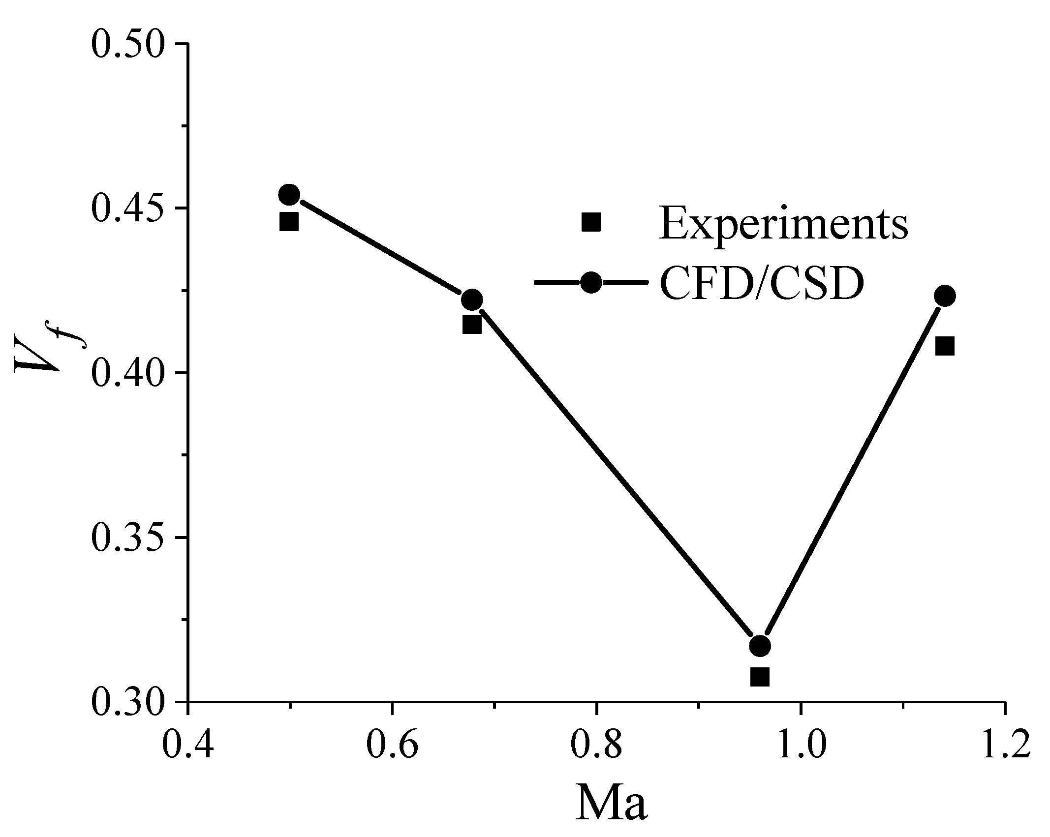
The Mach number of the experimental study is 0.50~1.14 in Ref. [39]. The dimensionless flutter critical velocity is predicted at Ma = 0.50 ,   0.68 ,   0.96 ,   and   1.14 . Figure 3 shows the experimental and computational results of dimensionless flutter critical velocity at different Mach numbers. Obviously, good agreement is obtained between the numerical solution and the experimental data whether supersonic or subsonic, with a maximum relative difference of approximately 6%. Therefore, the numerical method developed in this paper can be used for simulations related to aeroelasticity with high reliability.

4. Computational Model and Grid

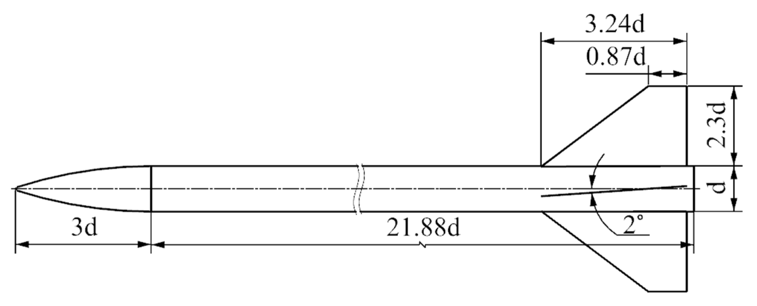
As a typical spinning projectile with a large aspect ratio, the Apache projectile is adopted for aeroelastic investigation. The model dimensions are shown in Figure 4. The diameter d of the projectile is chosen as a standard. The Apache consists of a 3d arched head, a 21.88d cylindrical body, and four tail fins with an installation angle ( δ = 2 ° ). The aspect ratio L/d is 24.88.
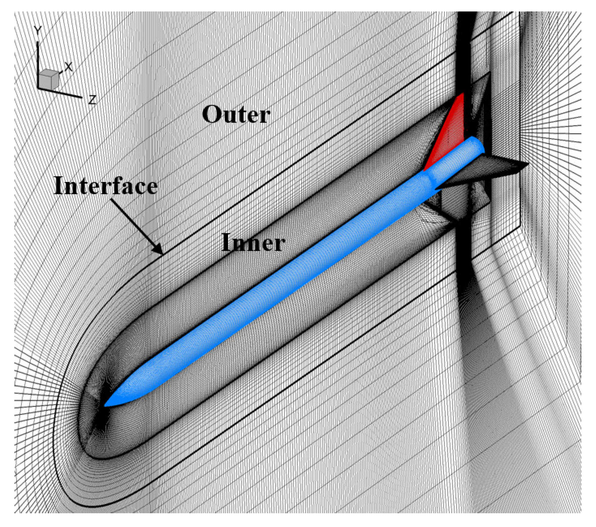
Figure 5 shows the mesh for the flow calculation of the Apache. The outer domain and the inner domain constitute the whole computational domain, which are connected by the interface. Numerical interpolation is employed at the interface to ensure the conservation of flux between the two domains. Both the inner and outer domains are composed of structured hexahedral grids, with a total number of grids of about 3.16 million. The rigid-motion mesh method and RBF mesh deformation method are used to adjust the meshes of the inner domain to adapt to the spinning and deformation of the projectile, while the meshes of the outer domain remain unchanged. The boundary conditions in the forward and circumferential direction are the freestream condition. The boundary in the projectile’s base direction is set to pressure outlet. The projectile’s surface is set to no-slip and adiabatic wall conditions.
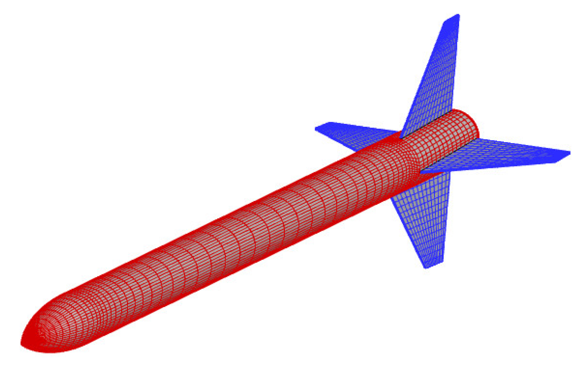
In Figure 6, the mesh for the structural calculation is displayed. In order to improve the accuracy of data exchange in the fluid-solid coupling calculation, the mesh for the structural calculation at the fluid-solid coupling interface should be as consistent as possible with that for the flow calculation. In this case, the divergence problem of the fluid-solid coupling calculation caused by data exchange at the fluid-solid interface can be effectively avoided. The deformation of the body is focused on in this paper, so the tail fins are assumed to be rigid bodies.
With the motivation of analyzing the influence of spinning and aerodynamics on the structural characteristics of the projectile, the natural frequency of the Apache is obtained by modal analysis. The first six natural frequencies of the Apache without rigid motion are provided in Table 1. It is found that the difference between the natural frequencies of the first mode and the second one is small, while the third-fourth modes and the fifth-sixth ones exhibit similar properties.
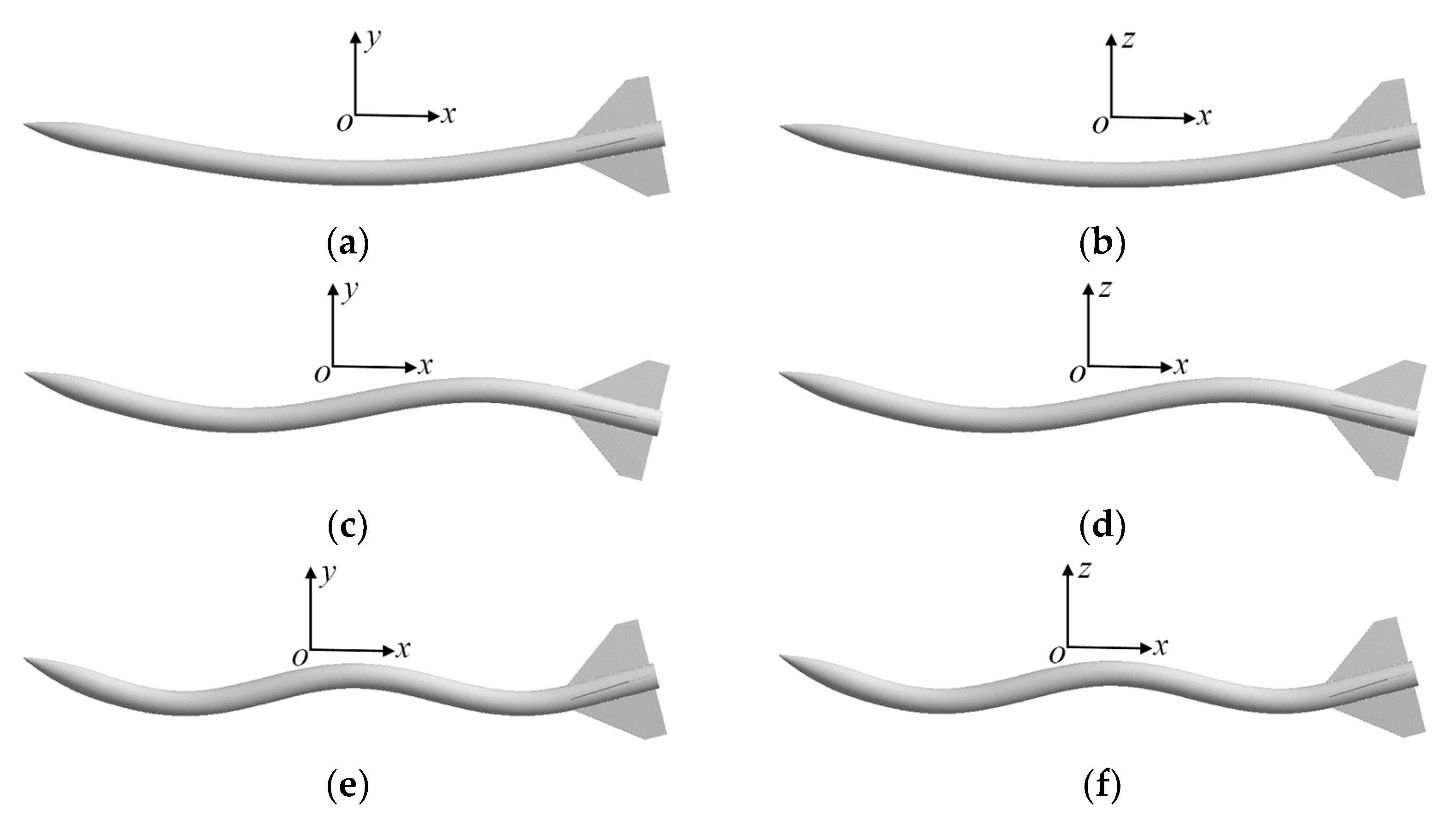
Figure A1 shows the first six mode shapes. From Figure A1, it is seen that the first, third, and fifth modes predominantly vibrate laterally, while the second, fourth, and sixth modes vibrate longitudinally. These modes can be grouped into three bending modes: the first and second modes represent the first bending mode, the third and fourth modes correspond to the second bending mode, and the fifth and sixth modes correspond to the third bending mode.

5. Results and Discussion

In this section, the aeroelastic response of the spinning projectile is numerically investigated under the conditions of Mach number Ma = 3 , Reynolds number R e L = 1.54 × 10 7 , attack angle α = 0 ° ~ 12 ° , and spinning speed ω x = 0 ~ 10 r / s . Here, “r/s” stands for “revolutions per second.” Furthermore, the dynamic aeroelastic responses and the variation in aerodynamic characteristics are obtained. Notably, if no special instructions are given, the head vertex of the Apache is selected as the monitoring point to analyze the variation in the deformation with time.

5.1. Effects of Spinning Motion

5.1.1. Dynamic Aeroelastic Response

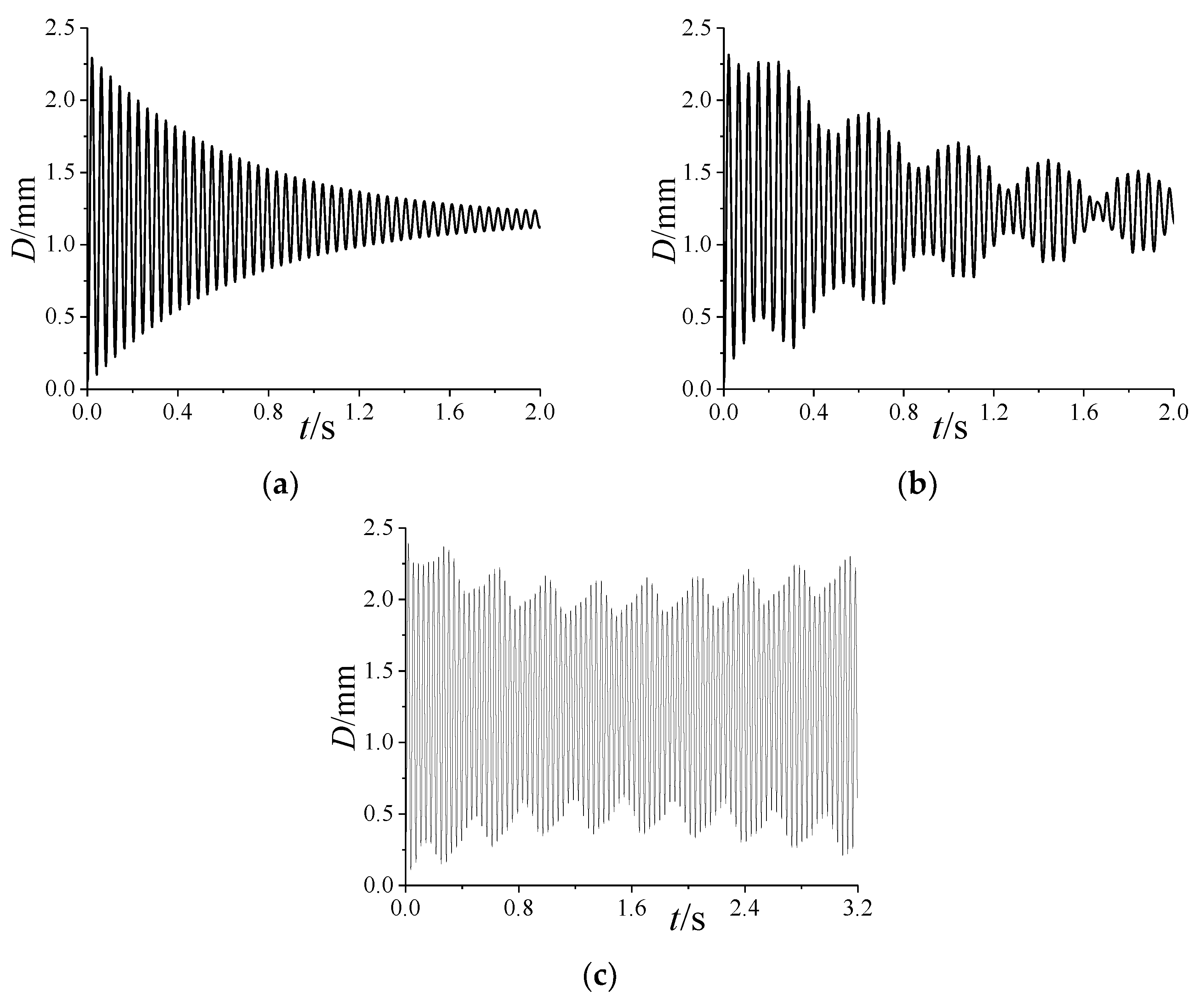
Figure 7 shows the variation in the total deformation with ω x . Obviously, the vibration curve tends to converge over time when ω x is 0 or 5 r / s , but for ω x = 10 r / s , it tends to diverge. Notably, when ω x 0 , the envelope of the vibration curves is in the shape of candied haws. That is, the amplitude of the curves fluctuates periodically. Specifically, the vibration period and frequency of the amplitude are, respectively, about 0.40 s and 2.50 Hz when ω x = 5 r / s , but for ω x = 10 r / s , they are, respectively, about 0.35 s and 2.82 Hz. Moreover, the time-averaged value of total deformation is almost the same at different ω x .
According to the characteristics of the curves in Figure 7, the total deformation can be expressed as:
D = D ¯ + D V D V = n D n sin (   ω n t + θ n )
where D represents the time-averaged total deformation, which is mainly determined by the time-averaged aerodynamic force. D V denotes the vibration of the total deformation, which mainly depends on the aerodynamic vibration. Since D V determines whether the deformation converges, it will be mainly analyzed in the following. n is a positive integer. D n , ω n , and θ n , respectively, represent the amplitude, frequency, and phase of D V . Notably, D is equivalent to the pre-deformation applied to the projectile, which decreases the vibration amplitude of the projectile under the periodic aerodynamic load. That is, it can be considered that D increases the stiffness of the projectile. Thus, D n is reduced due to the increase in D , which is beneficial to the convergence of aeroelastic deformation.
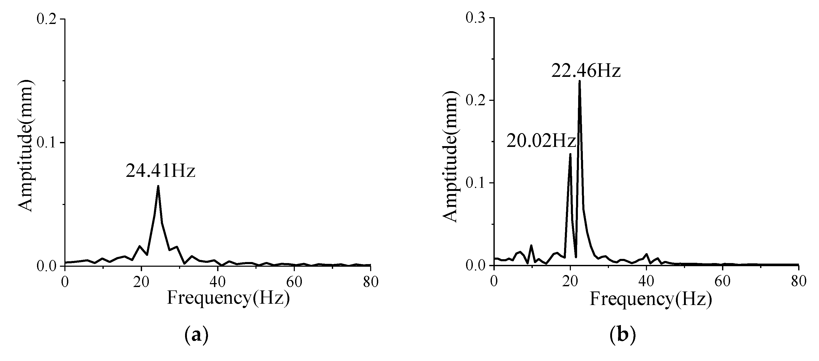
Due to the rapid attenuation of the curves at the early stages in Figure 7, the vibration curves after 1.20 s are selected to analyze amplitude-frequency characteristics. In Figure 8, the amplitude-frequency curves of the total deformation after 1.20 s under different ω x are obtained by the Fourier transform. As shown in Figure 8a, when ω x = 0 , there is only one peak frequency of 24.41 Hz in the amplitude-frequency curve, which is greater than the first two natural frequencies 21.81 Hz and 22.22 Hz of the projectile shown in Table 1. In order to explain the reason for the increase in frequency, a wet modal analysis for the projectile was carried out under the conditions of Ma = 3, R e L = 1.54 × 10 7 , and α = 4 ° . The results show that the first two natural frequencies are increased to 24.13 Hz and 24.24 Hz, respectively, which are very close to the peak frequency of 24.41 Hz. In fact, according to the above analysis, it can be seen that D increases the stiffness of the projectile in disguised form, thereby increasing its natural frequencies.
In Figure 8b, when ω x = 5 r / s , there are two peak frequencies of 20.02 Hz and 22.46 Hz. Owing to the small difference between the two (denoted as f ω 5 = 2.44 H z ), a beat vibration may occur. As mentioned previously, the vibration frequency of the amplitude in Figure 7b is 2.50 Hz, which is almost equal to the difference f ω 5 . It is consistent with the judgment conditions of the beat vibration in Ref. [40]. That is, the beat vibration phenomenon is induced during the vibration process of the projectile. The beat vibration is more likely to cause structural fatigue failure and collisions between the structures inside the projectile, which results in a very dangerous working state for the projectile. Moreover, the two peak frequencies of 20.02 Hz and 22.46 Hz are close to the first two natural frequencies of 21.81 Hz and 22.22 Hz for the projectile without rigid motion shown in Table 1. Yet, the difference f ω 5 is greater than that of 0.41 Hz between the first two natural frequencies. This indicates that the rotational motion leads to the increasing difference between two adjacent natural frequencies.
As shown in Figure 8c, when ω x = 10 r / s , there are two peak frequencies of 19.72 Hz and 22.51 Hz in the amplitude–frequency curve. The difference f ω 10 between them is 2.79 Hz, which is almost equal to the vibration frequency of 2.82 Hz for the amplitude in Figure 7c. In this case, the beat vibration can also be induced. Notably, the f ω 10 is greater than f ω 5 , which declares that the difference between the first two natural frequencies increases with the increase in ω x . Therefore, even for the axisymmetric projectile, the spinning motion will cause the separation of the first two natural frequencies to induce the beat vibration, which aggravates the influence of deformation on the flight performance of the projectile.
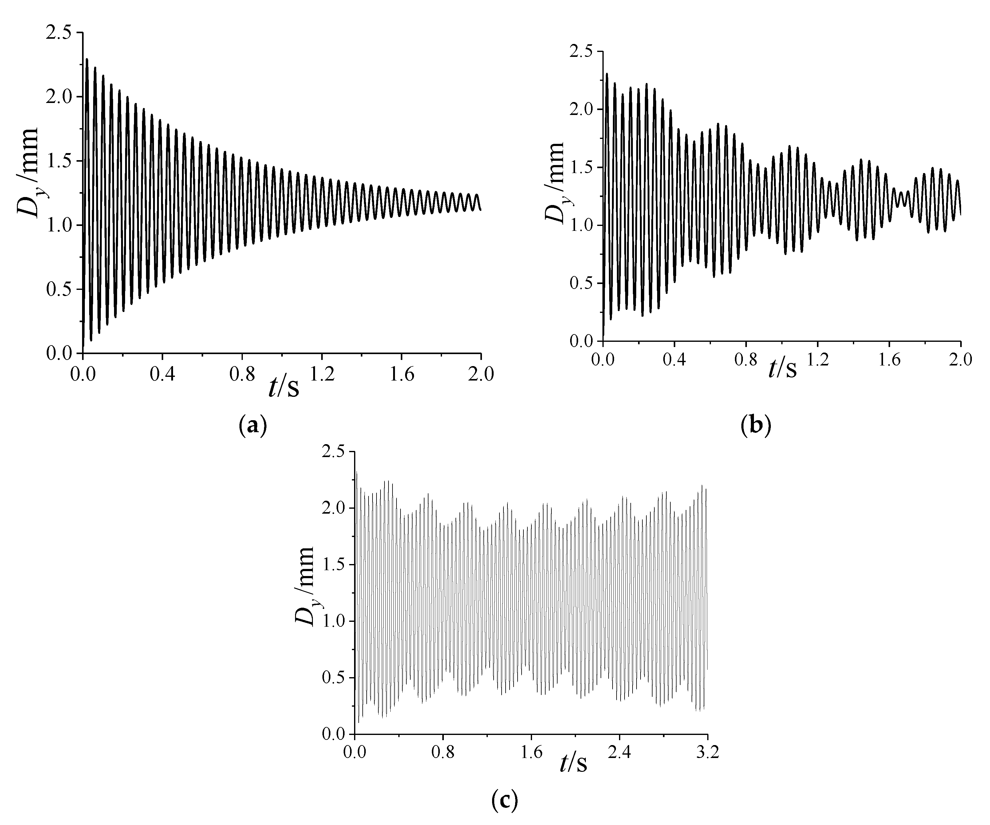
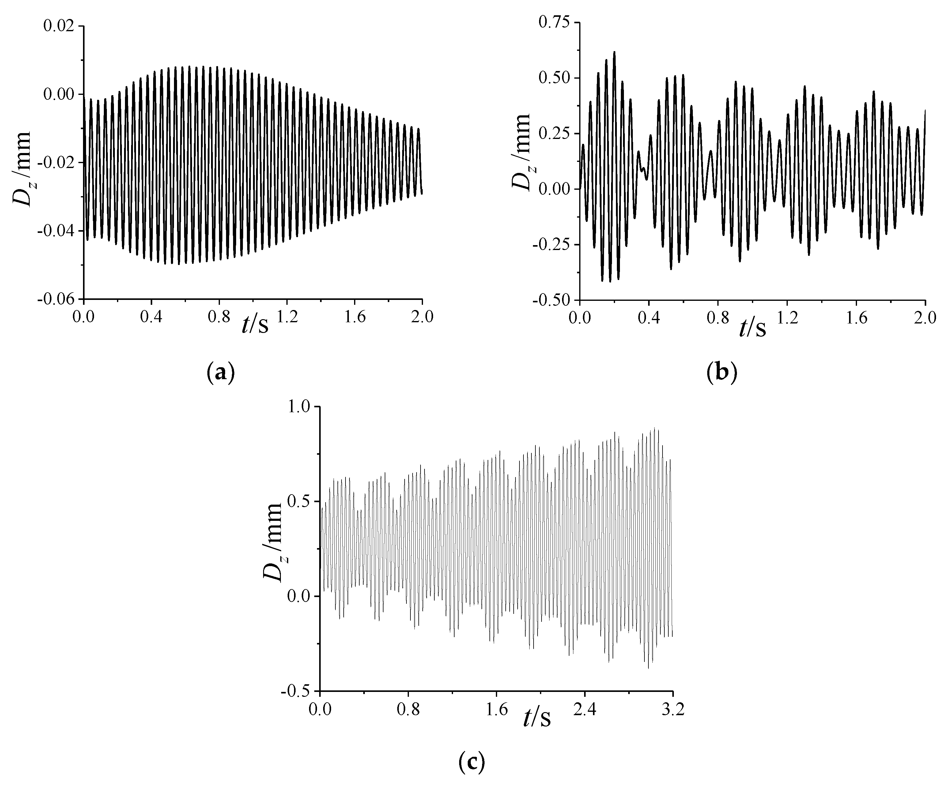
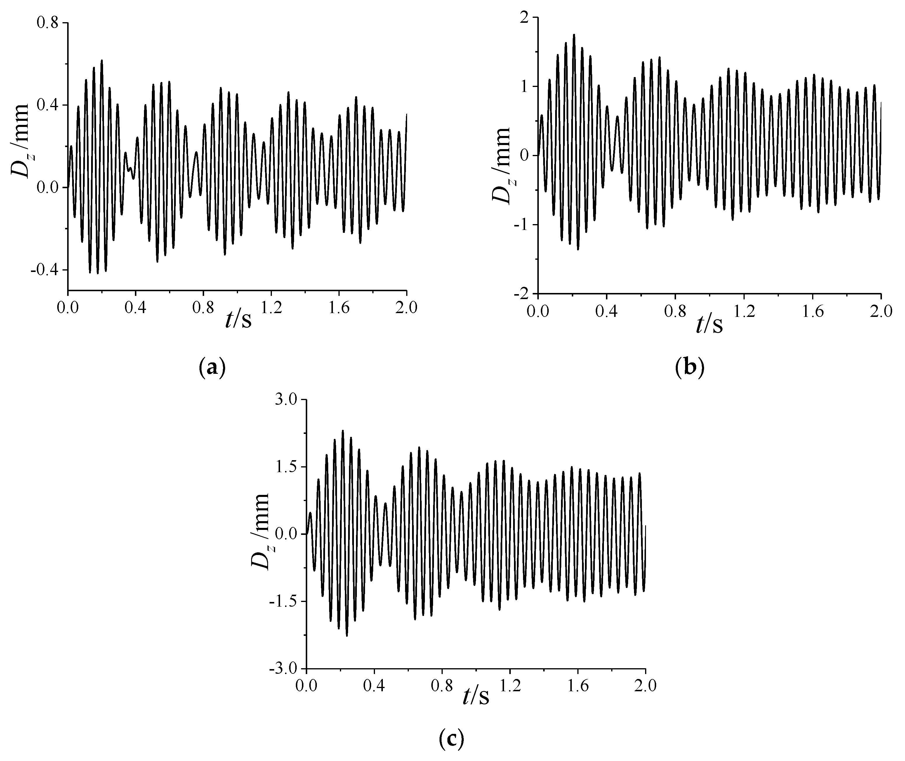
Figure A2 and Figure A3 in Appendix A depict, respectively, the variations in the longitudinal deformation and lateral deformation with ω x . It can be observed that when ω x = 0 , there is only one vibration frequency in the curves, while for ω x 0 , there arise beat vibrations induced by two waves with different frequencies. This indicates that the first two modes are coupled due to the spinning motion. Moreover, when ω x = 10 r / s , the divergence of the lateral vibration will cause a gradual transition of the longitudinal vibration from convergence to divergence. The reason for this phenomenon can be explained by the difference between the longitudinal time-averaged deformation D y and the lateral one D z . From the comparison of Figure A2 and Figure A3, it is seen that D z is smaller than D y at different ω x , that is, the lateral stiffness is smaller. This results in a larger amplitude for the lateral vibration than the longitudinal one under the same periodic aerodynamic load. Therefore, it is easier to cause the lateral vibration to diverge than the longitudinal one.

5.1.2. Variation in Aerodynamic Characteristics

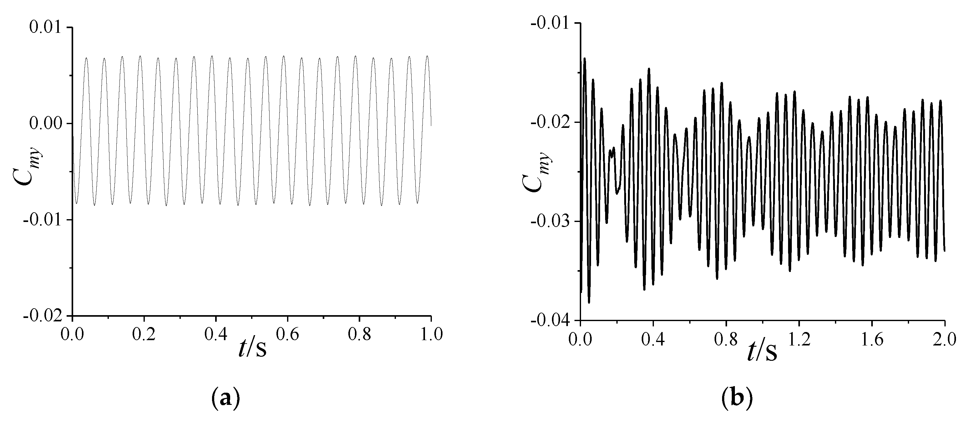
Figure A4 and Figure A5 illustrate the variation in the yawing moment coefficient C m y at different ω x . As shown in Figure A4a and Figure A5a, when ω x increases, the amplitude of C m y increases due to the Magnus effect, which leads to an increase in the amplitude of the lateral vibration. Thus, it is easier to cause divergence in the lateral vibration. In Figure A4b and Figure A5b, when the projectile is deformed, the amplitude and frequency of C m y have similar variations to that of the lateral deformation. This suggests that aerodynamic forces and structural deformation are coupled.

5.2. Effects of Attack Angle

5.2.1. Dynamic Aeroelastic Response

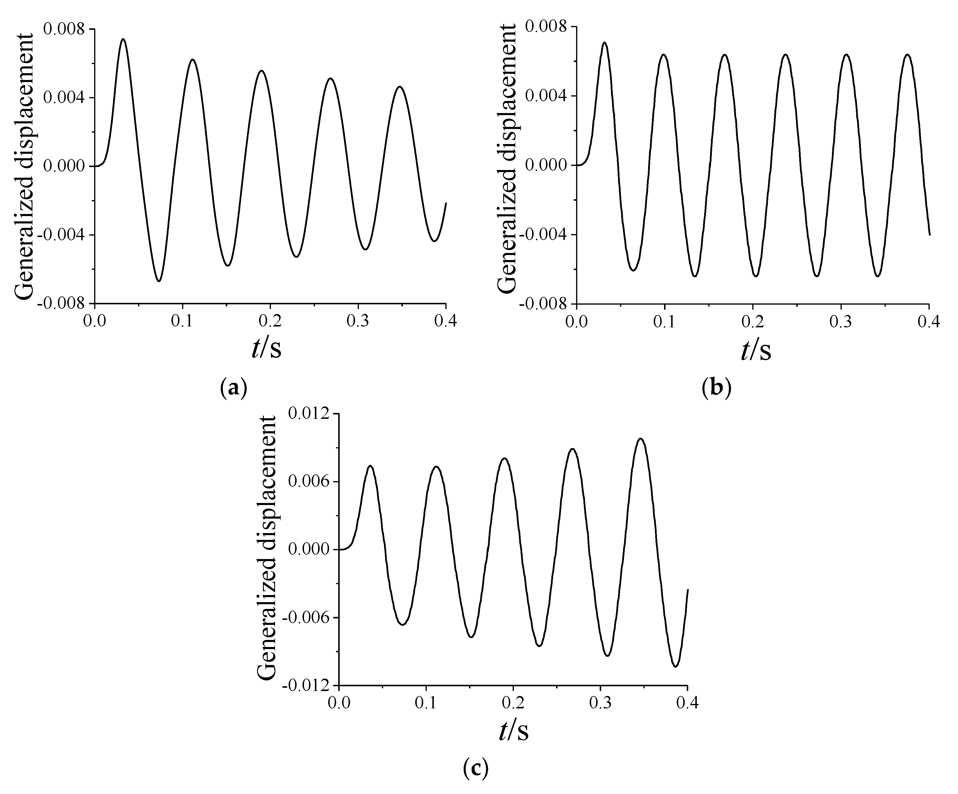
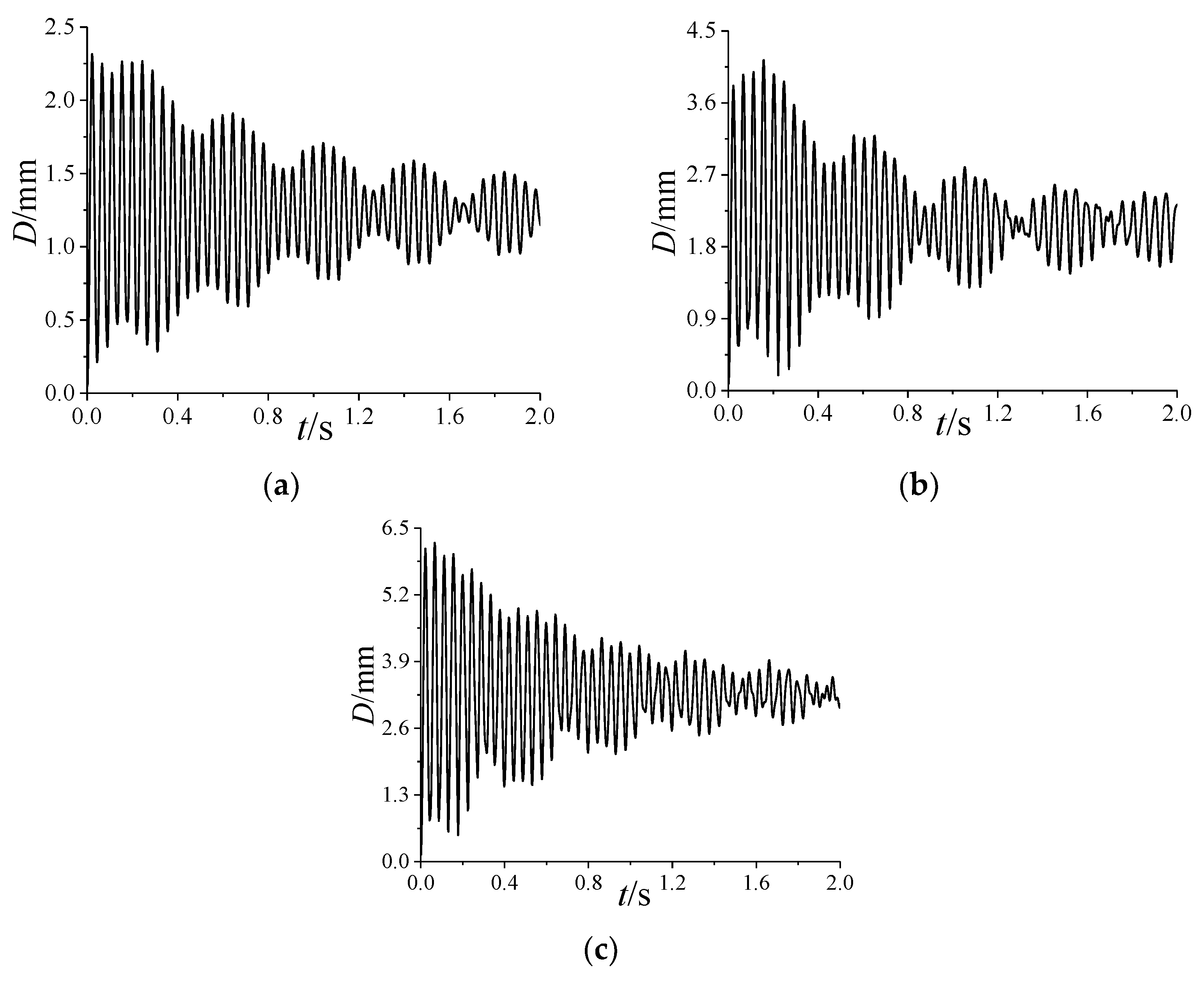
Figure 9 depicts the variation in the total deformation with α . It can be observed that the amplitude of the vibration curve exhibits periodic fluctuations at various values of α , indicating the presence of beat vibrations. However, the beat vibration induced under α = 12 ° is not as obvious as that when α is 4 ° or 8 ° . Moreover, with the increase in α , the total deformation increases, which is due to the increase in the normal aerodynamic load.
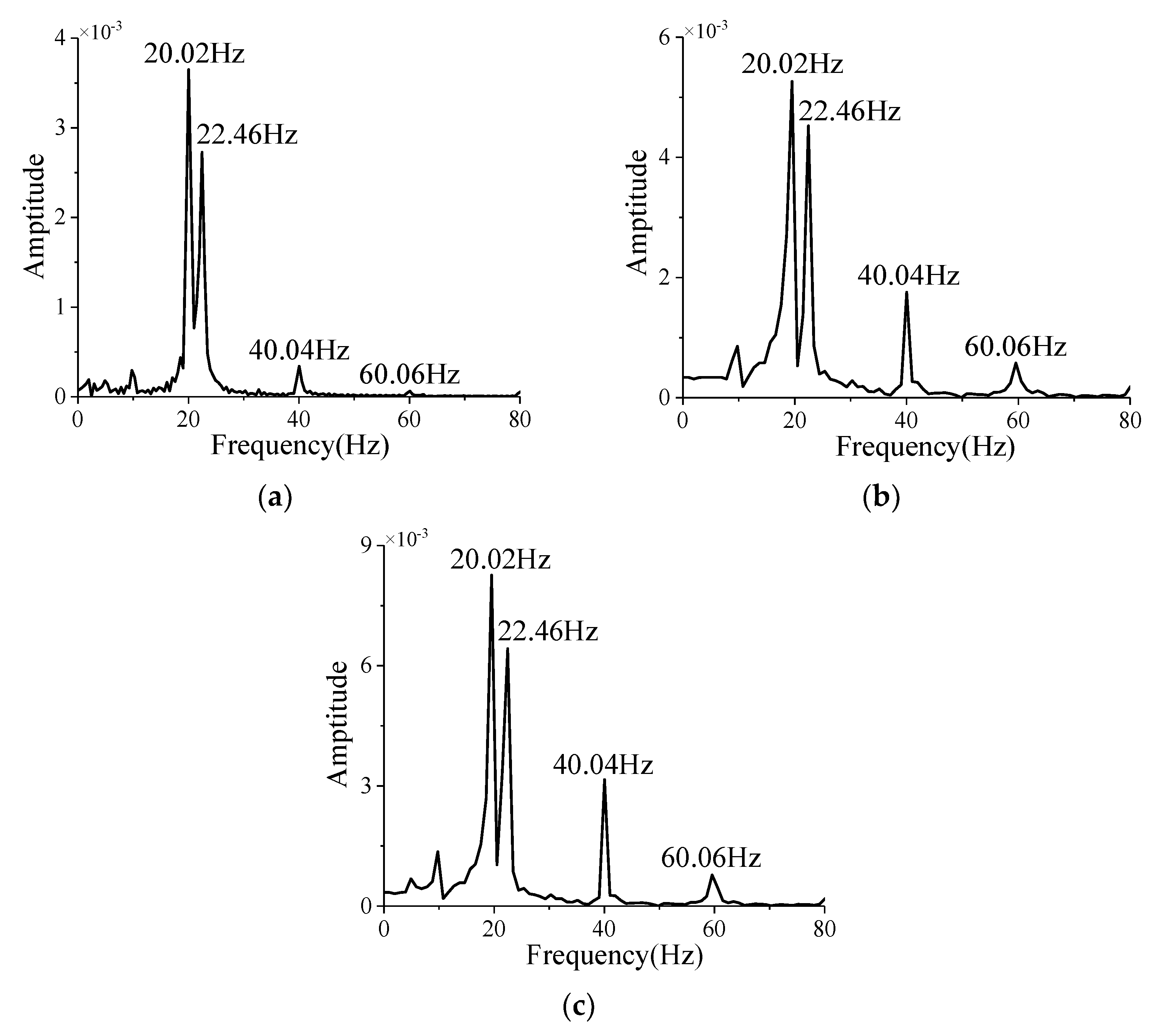
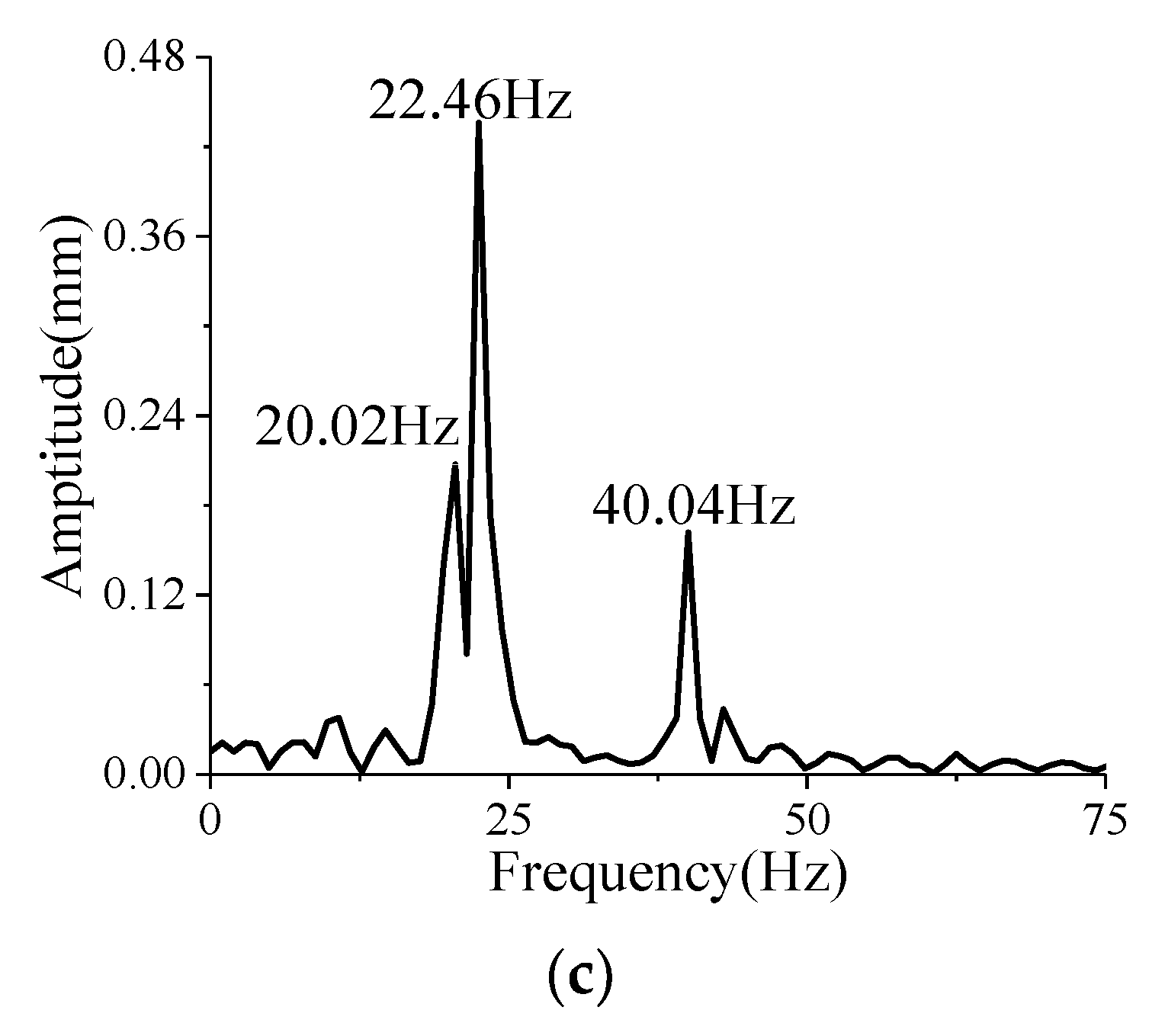
In Figure 10, the amplitude–frequency curves of the total deformation after 1.20 s under different α are shown by the Fourier transform. It is found that there are at least two peak frequencies of 20.02 Hz and 22.46 Hz as α increases. For α =   8 ° or α = 12 ° , the third peak frequency of 40.04 Hz appears. Due to the small difference between the peak frequencies of 20.02 Hz and 22.46 Hz, beat vibration will occur. The third peak frequency of 40.04 Hz is the frequency of the forced vibration induced by unsteady aerodynamic force, which will be analyzed later. Notably, the amplitude of the first two natural frequencies is the largest, which means that the bending shape of the projectile under external load mainly manifests as the first two vibration modes. Moreover, in terms of the amplitudes corresponding to the first two peak frequencies, the difference between the two is small when α is 4 ° or 8 ° , which leads to the obvious beat vibration in Figure 9b,c. However, the difference increases when α = 12 ° , which results in the weak beat vibration phenomenon.
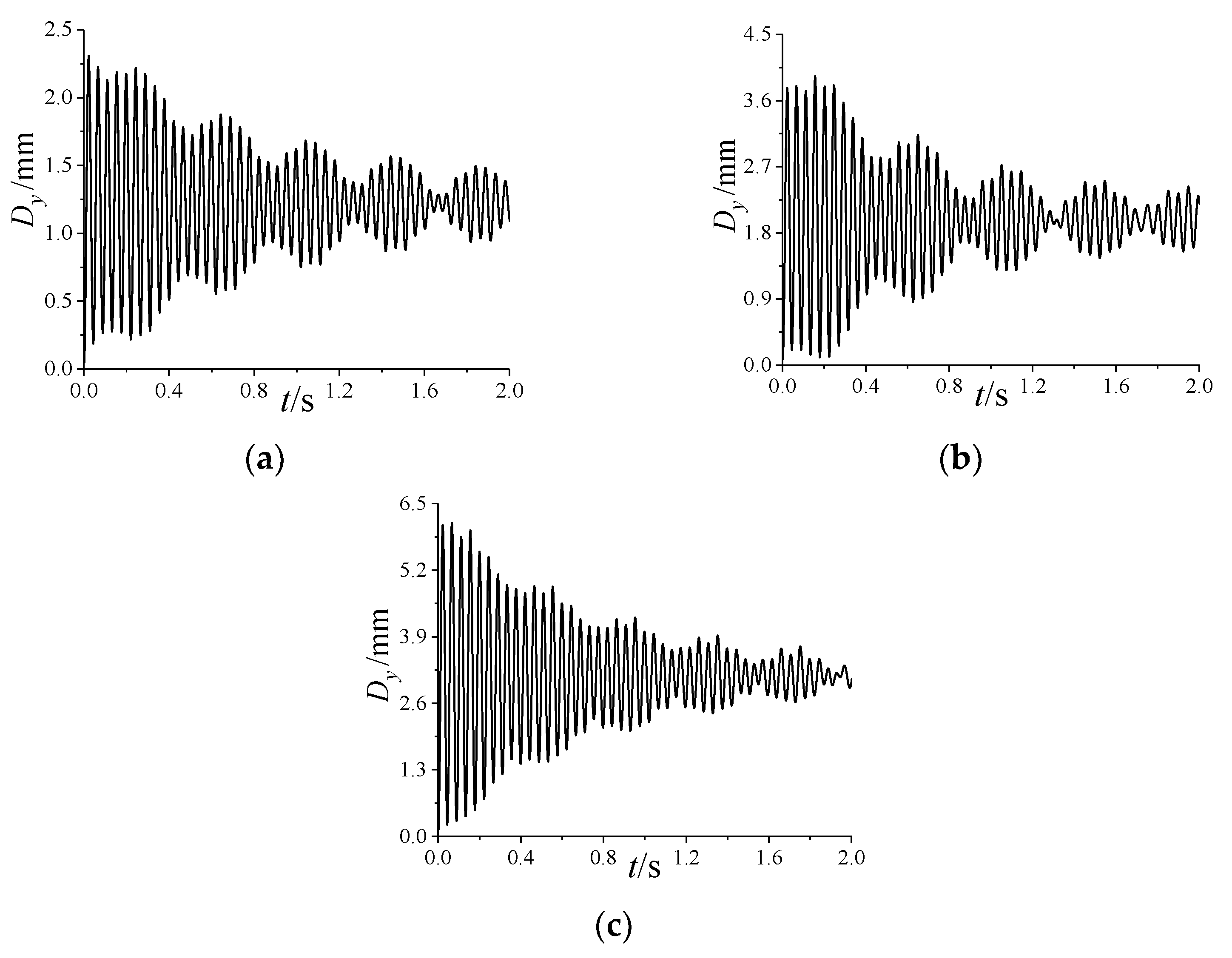
Figure A6 and Figure A7, respectively, show the variation in the longitudinal and lateral deformations with α . As shown in Figure A6, when α increases, the time-averaged value of longitudinal deformation increases. That is, the longitudinal pre-deformation increases, which is equivalent to increasing the longitudinal stiffness of the projectile. Under different α , there exists a beat vibration in the longitudinal deformation, which is consistent with the variation in the total deformation in Figure 9. As shown in Figure A7, the time-averaged value of lateral deformation is close to zero at different α . Notably, for the lateral deformation within 1.20 s~2.00 s, the beat vibration is weakened with the increase in α .
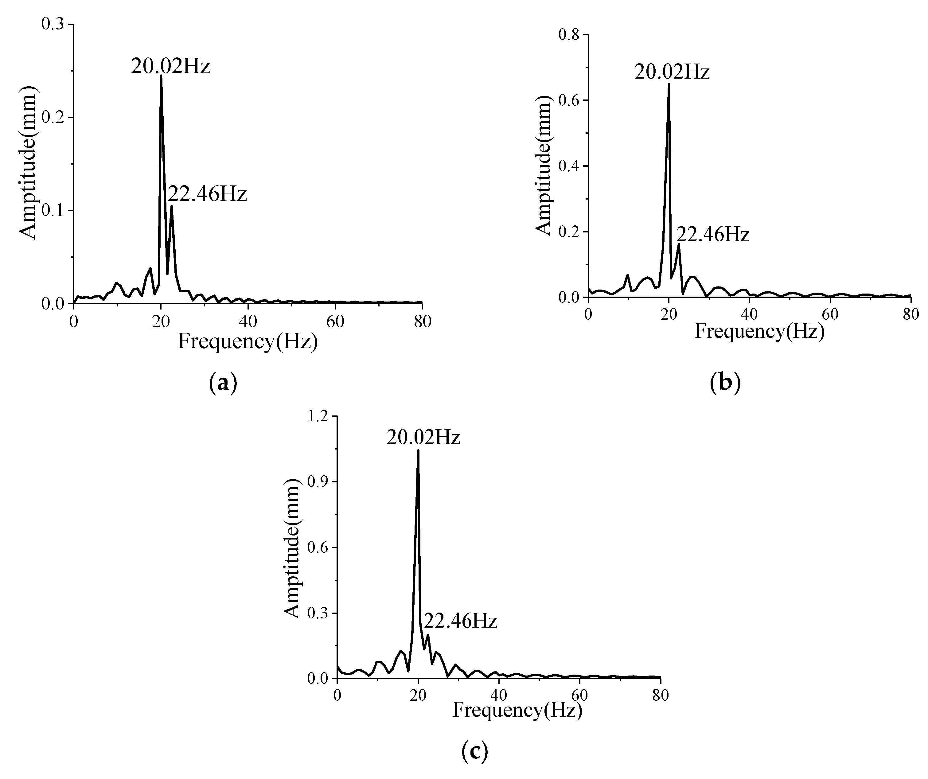
As shown in Figure A8, the amplitude-frequency curves of the lateral deformation under different α are obtained by the Fourier transform for the curves after 1.20 s in Figure A7. It can be seen that there are only two peak frequencies of 20.02 Hz and 22.46 Hz. The amplitude corresponding to 22.46 Hz gradually decreases with the increase in α , which weakens the beat vibration for the lateral deformation within 1.20 s~2.00 s. This illustrates that the time−averaged aeroelastic deformation increases as α increases, which increases the stiffness in disguised form and reduces the coupling between the first two modes. And then the beat vibration is weakened. For the lateral deformation, the variation in the beat vibration with α mentioned above satisfies the conclusion. However, for the longitudinal deformation, the two are incompletely consistent, which will be explored later.

5.2.2. Variation in Aerodynamic Characteristics

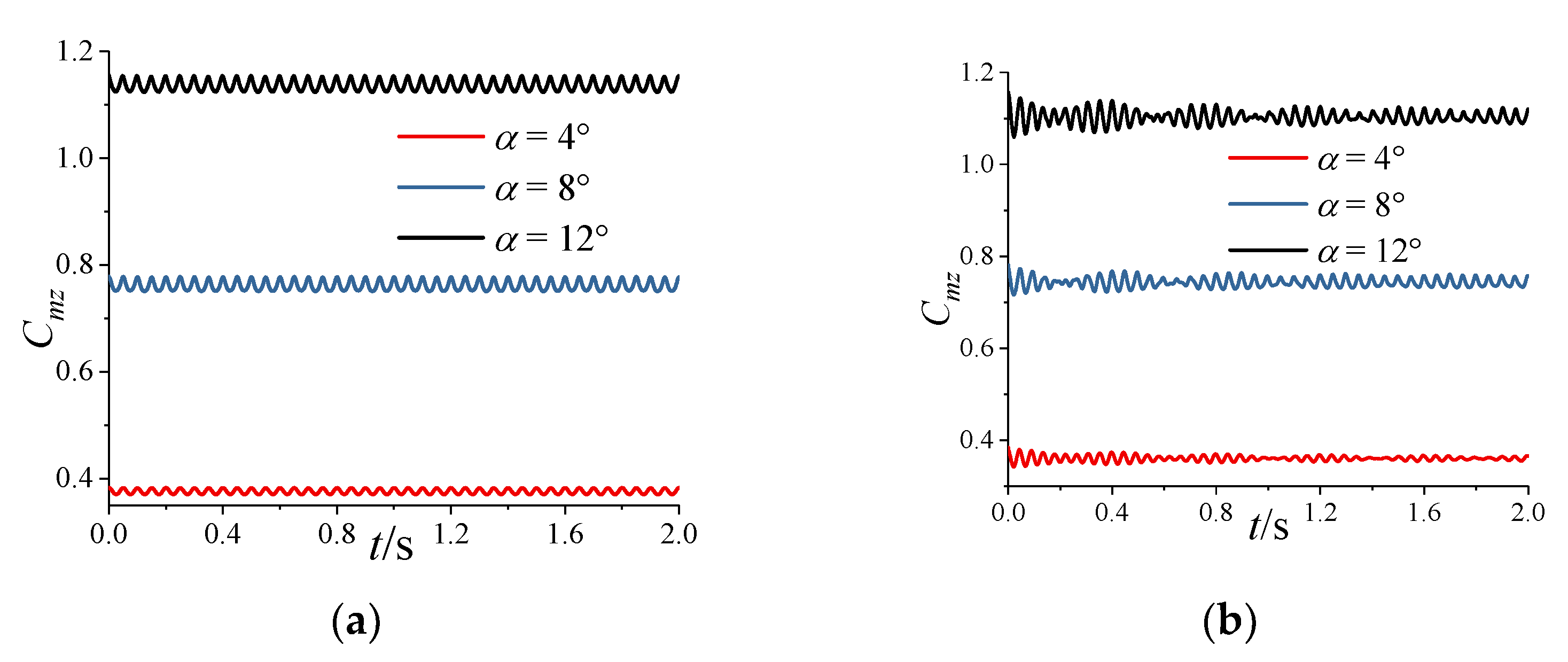
Figure A9 shows the variation in the pitching moment coefficient C m z with α under undeformed or deformed conditions. In Figure A9a, the frequency and amplitude of C m z for the undeformed projectile under different α remain unchanged with time. The variation in the C m z of the deformed projectile in Figure A9b is similar to that of longitudinal vibration in Figure A6. Whether the projectile is deformed or not, the time−averaged values of C m z change little.
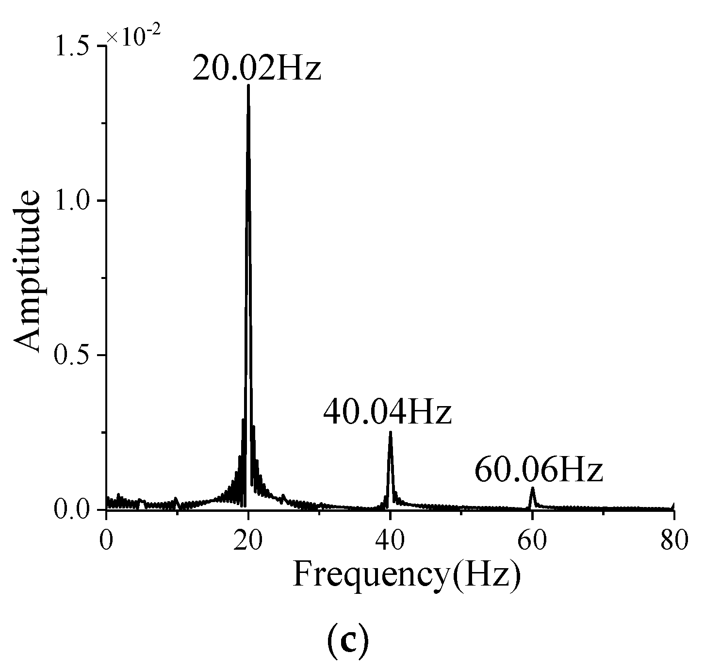
As shown in Figure A10 and Figure A11, the amplitude-frequency curves of C m z at different α are determined by the Fourier transform. In Figure A10, there are three peak frequencies of 20.02 Hz, 40.04 Hz, and 60.06 Hz for the C m z without deformation, which are about 4 times, 8 times, and 12 times the spinning frequency f x , respectively. This indicates that the C m z without deformation is mainly composed of the components with frequencies of 4 f x , 8 f x , and 12 f x , and the corresponding amplitudes decrease sharply with the increase i frequency. For ω x = 5 r / s , 4 f x is close to the first two natural frequencies of the projectile, which induces the resonance. The component with a frequency of 8 f x causes a forced vibration, which makes the third natural frequency appear in the amplitude–frequency curves of the total deformation shown in Figure 10. The amplitude of the component with a frequency of 12 f x is too small to affect the deformation of the projectile.
The reason for the obvious beat vibrations that appear in Figure 9 when α is 4 ° and 8 ° can be explained by Figure A9 and Figure A10. From Figure A9, when α increases from 4 ° to 8 ° , the increase in C m z aggravates the time-averaged deformation of the projectile, which enhances its stiffness in disguised form. That reduces the coupling between the first two modes to weaken the beat vibration. However, Figure A10 suggests that the amplitude of C m z increases sharply, which causes an increase in the periodic external excitation on the projectile. Therefore, there is also an obvious beat vibration when α = 8 ° . When α increases from 8 ° to 12 ° , the C m z increases while the amplitude remains almost unchanged, which results in the beat vibration at α =   12 ° being less obvious than that at α = 8 ° .
As shown in Figure A11, there are four peak frequencies of 20.02 Hz, 22.46 Hz, 40.04 Hz, and 60.06 Hz in the amplitude–frequency curves of C m z with deformation. The first two are 20.02 Hz and 22.46 Hz, respectively, which correspond to those of the projectile vibration shown in Figure 10. This indicates that there is a certain coupling between the deformation and the aerodynamic force. Moreover, Figure A11 demonstrates that the deformation causes the amplitude corresponding to 4 f x to decrease, while that corresponding to 8 f x or 12 f x increases. And the larger α is, the more obvious this rule is.

6. Conclusions

A numerical simulation method for the aeroelasticity of spinning projectiles is developed by the use of coupled aerodynamics and structural dynamics in this paper. The loosely coupled method is utilized to realize the coupled solving of the fluid and structural equations considering rotation effect. The rigid-motion mesh method is used to treat the spinning motion, while the RBF mesh deformation method is exploited for the aeroelastic deformation. The correspondence between the solid and fluid meshes is established by the search algorithm combining the hierarchical octree and bucket algorithms at the fluid–solid interface, and then the inverse isoparametric interpolation method is employed for the fluid-solid data transmission. Based on the numerical method developed in this paper, the aeroelastic response of spinning projectiles with large slenderness ratio is numerically researched to analyze its structure and aerodynamic characteristics. The following conclusions can be drawn:
  • The coupling of the first two modes of projectiles induced by the spinning motion can lead to the occurrence of beat vibration, which causes the amplitude of the vibration to fluctuate periodically;
  • The increase in the angle of attack reduces the coupling degree of the first two modes, which weakens the beat vibration; the increase in spinning speed causes the difference between the first two natural frequencies to increase, which induces a more obvious beat vibration phenomenon;
  • The time-averaged aeroelastic deformation caused by time-averaged aerodynamic loads is beneficial to the convergence of the vibration of the spinning projectile, but the rotation-induced Magnus effect makes the vibration more easily divergent.

Author Contributions

Conceptualization, Q.L. and J.L.; methodology, Q.L.; software, J.L.; validation, Q.L., Y.Y. and J.Y.; formal analysis, Q.L.; investigation, Q.L. and J.L.; resources, J.L. and Y.Y.; data curation, Q.L.; writing—original draft preparation, Q.L.; writing—review and editing, Q.L., J.L., Y.Y. and J.Y.; visualization, Q.L.; supervision, J.L.; project administration, J.L.; funding acquisition, J.L. All authors have read and agreed to the published version of the manuscript.

Funding

This research was funded by the National Natural Science Foundation of China, grant number 11372040.

Data Availability Statement

Not applicable.

Conflicts of Interest

The authors declare no conflict of interest.

Appendix A

Figure A1. The first six mode shapes: (a) the first mode shape; (b) the second mode shape; (c) the third mode shape; (d) the fourth mode shape; (e) the fifth mode shape; (f) the sixth mode shape.
Aerospace 10 00646 g0a1
Figure A2. Variation in the longitudinal deformation with ω x at Ma = 3, R e L = 1.54 × 10 7 , and α = 4 ° : (a) ω x = 0 ; (b) ω x = 5 r / s ; (c) ω x = 10 r / s .
Aerospace 10 00646 g0a2
Figure A3. Variation in the lateral deformation with ω x at Ma = 3, R e L = 1.54 × 10 7 , and α = 4 ° : (a) ω x = 0 ; (b) ω x = 5 r / s ; (c) ω x = 10 r / s .
Aerospace 10 00646 g0a3
Figure A4. The yawing moment coefficient C m y under the undeformed or deformed conditions at Ma = 3, R e L = 1.54 × 10 7 , α = 4 ° , and ω x = 5 r / s : (a) undeformed; (b) deformed.
Aerospace 10 00646 g0a4
Figure A5. The yawing moment coefficient C m y under the undeformed or deformed conditions at Ma = 3, R e L = 1.54 × 10 7 , α = 4 ° , and ω x = 10 r / s : (a) undeformed; (b) deformed.
Aerospace 10 00646 g0a5
Figure A6. Variation in the longitudinal deformation with α at Ma = 3, R e L = 1.54 × 10 7 , and ω x = 5 r / s : (a) α = 4 ° ; (b) α = 8 ° ; (c) α = 12 ° .
Aerospace 10 00646 g0a6
Figure A7. Variation in the lateral deformation with α at Ma = 3, R e L = 1.54 × 10 7 , and ω x = 5 r / s : (a) α = 4 ° ; (b) α = 8 ° ; (c) α = 12 ° .
Aerospace 10 00646 g0a7
Figure A8. Amplitude–frequency curves of the lateral deformation under different α at Ma = 3, R e L = 1.54 × 10 7 , and ω x = 5 r / s : (a) α = 4 ° ; (b) α = 8 ° ; (c) α = 12 ° .
Aerospace 10 00646 g0a8
Figure A9. Variation in the pitching moment coefficient C m z with α under the undeformed or deformed conditions at Ma = 3, R e L = 1.54 × 10 7 , and ω x = 5 r / s : (a) undeformed; (b) deformed.
Aerospace 10 00646 g0a9
Figure A10. Amplitude–frequency curves of the C m z without deformation under different α at Ma = 3, R e L = 1.54 × 10 7 , and ω x = 5 r / s : (a) α = 4 ° ; (b) α = 8 ° ; (c) α = 12 ° .
Aerospace 10 00646 g0a10aAerospace 10 00646 g0a10b
Figure A11. Amplitude–frequency curves of the C m z with deformation under different α at Ma = 3, R e L = 1.54 × 10 7 , and ω x = 5 r / s : (a) α = 4 ° ; (b) α = 8 ° ; (c) α = 12 ° .
Aerospace 10 00646 g0a11

References

  1. Curry, W.H.; Uselton, J.C. Some comments on the aerodynamic characteristics of the Tomahawk sounding rocket. In Proceedings of the Sounding Rocket Vehicle Technology Specialist Conference, Williamsburg, VA, USA, 27 February–1 March 1967; p. 1312. [Google Scholar]
  2. Reis, G.E.; Sundberg, W.D. Calculated aeroelastic bending of a sounding rocket based on flight data. J. Spacecr. Rockets 1971, 4, 1489–1494. [Google Scholar] [CrossRef]
  3. Cochran, J.E., Jr.; Christensen, D.E. Free−flight rocket attitude motion due to transverse vibration. J. Spacecr. Rockets 1980, 17, 425–431. [Google Scholar] [CrossRef]
  4. Flatus, D.H. Aeroelastic stability of slender, spinning missiles. J. Guid. Control Dyn. 1992, 15, 144–151. [Google Scholar] [CrossRef]
  5. Waszak, M.R.; Schmidt, D.K. Flight dynamics of aeroelastic vehicles. J. Aircr. 1988, 25, 563–571. [Google Scholar] [CrossRef]
  6. Buttrill, C.; Arbuckle, P.; Zeiler, T. Nonlinear simulation of a flexible aircraft in maneuvering flight. In Proceedings of the Flight Simulation Technologies Conference, Monterey, CA, USA, 17–19 August 1987; p. 2501. [Google Scholar]
  7. Waszak, M.R.; Buttrill, C.S.; Schmidt, D.K. Modeling and Model Simplification of Aeroelastic Vehicles: An Overview; NASA TM: Moffett Field, CA, USA, 1992; p. 107691.
  8. Oliveira, E.J.; Gasbarri, P.; Milagre da Fonseca, I. Flight dynamics numerical computation of a sounding rocket including elastic deformation model. In Proceedings of the AIAA Atmospheric Flight Mechanics Conference, Dallas, TX, USA, 22–26 June 2015; p. 2710. [Google Scholar]
  9. Schmidt, D.K.; Raney, D.L. Modeling and simulation of flexible flight vehicles. J. Guid. 2001, 24, 539–546. [Google Scholar] [CrossRef]
  10. Murphy, C.H.; Mermagen, W.H., Sr. Flight motion of a continuously elastic finned missile. J. Guid. 2003, 26, 89–98. [Google Scholar] [CrossRef] [Green Version]
  11. Li, Y.W.; Nahon, M.; Sharf, I. Dynamics modeling and simulation of flexible airships. AIAA J. 2009, 47, 592–605. [Google Scholar] [CrossRef] [Green Version]
  12. Saltari, F.; Riso, C.; Matteis, G.D.; Mastroddi, F. Finite−element−based modeling for flight dynamics and aeroelasticity of flexible aircraft. J. Aircr. 2017, 54, 2350–2366. [Google Scholar] [CrossRef]
  13. Verhaegen, A.; Żbikowski, R. Aeroservoelastic modelling and control of a slender anti−air missile for active damping of longitudinal bending vibrations. Aerosp. Sci. Technol. 2017, 66, 20–27. [Google Scholar] [CrossRef] [Green Version]
  14. Yang, C.; Xu, Y.; Xie, C.C. Review of studies on aeroelasticty of hypersonic vehicles. Astronaut. Sin. 2010, 31, 1–11. [Google Scholar]
  15. Blades, E.; Newman, J. Aeroelastic effects of spinning missiles. In Proceedings of the 48th AIAA/ASME/ASCE/AHS/ASC Structures, Structural Dynamics, and Materials Conference, Honolulu, HI, USA, 23–26 April 2007; p. 2243. [Google Scholar]
  16. Schütte, A.; Einarsson, G.; Raichle, A.; Schöning, B.; Mönnich, W.; Orlt, M.; Neumann, J.; Arnold, J.; Forkert, T. Numerical simulation of maneuvering aircraft by aerodynamic, flight mechanics and structural mechanics coupling. J. Aircr. 2009, 46, 53–64. [Google Scholar] [CrossRef]
  17. Kim, J.Y.; Cho, S.I.; Lee, I.; Paek, S.K. Flutter Characteristics of a Rolling Wraparound Fin Projectile Considering Aeroelastic Deflections. J. Spacecr. Rockets 2012, 49, 709–719. [Google Scholar] [CrossRef]
  18. Li, H.; Ye, Z.Y. Effects of rotational motion on dynamic aeroelasticity of flexible spinning missile with large slenderness ratio. Aerosp. Sci. Technol. 2019, 94, 105384. [Google Scholar] [CrossRef]
  19. Abbas, L.K.; Chen, D.Y.; Rui, X.T. Numerical calculation of effect of elastic deformation on aerodynamic characteristics of a rocket. Int. J. Aerosp. Eng. 2014, 2014, 478534. [Google Scholar] [CrossRef] [Green Version]
  20. Li, M.J.; Rui, X.T.; Abbas, L.K. Elastic dynamic effects on the trajectory of a flexible launch vehicle. J. Spacecr. Rockets 2015, 52, 1586–1602. [Google Scholar] [CrossRef]
  21. Hua, R.H.; Ye, Z.Y.; Wu, J. Effect of elastic deformation on flight dynamics of projectiles with large slenderness ratio. Aerosp. Sci. Technol. 2017, 71, 347–359. [Google Scholar] [CrossRef]
  22. Yang, L.; Ye, Z.Y.; Wu, J. The influence of the elastic vibration of the carrier to the aerodynamics of the external store in air−launch−to−orbit process. Acta Astronaut. 2016, 128, 440–454. [Google Scholar] [CrossRef] [Green Version]
  23. Lu, T.Y.; Wu, X.S.; Lei, J.M.; Yin, J.T. Numerical study on the aerodynamic coupling effects of spinning and coning motions for a finned vehicle. Aerosp. Sci. Technol. 2018, 77, 399–408. [Google Scholar] [CrossRef]
  24. Hua, R.; Yuan, X.; Tang, Z.; Ye, Z. Study on flight dynamics of flexible projectiles based on closed−loop feedback control. Aerosp. Sci. Technol. 2019, 90, 327–341. [Google Scholar] [CrossRef]
  25. Yin, J.T.; Lei, J.M.; Wu, X.S.; Lu, T.Y. Effect of elastic deformation on the aerodynamic characteristics of a high−speed spinning projectile. Aerosp. Sci. Technol. 2015, 45, 254–264. [Google Scholar] [CrossRef]
  26. Yin, J.; Lei, J.; Wu, X.; Lu, T. Aerodynamic characteristics of a spinning projectile with elastic deformation. Aerosp. Sci. Technol. 2016, 51, 181–191. [Google Scholar] [CrossRef]
  27. Kamakoti, R.; Shyy, W. Fluid–structure interaction for aeroelastic applications. Prog. Aerosp. Sci. 2004, 40, 535–558. [Google Scholar] [CrossRef]
  28. Pandya, S.A.; Venkateswaran, S.; Pulliam, T.H. Implementation of preconditioned dual−Time procedures in overflow. In Proceedings of the 41st AIAA Aerospace Sciences Meeting and Exhibit, Reno, NV, USA, 6–9 January 2003; p. 72. [Google Scholar]
  29. Vatsa, V.; Turkel, E. Choice of variables and preconditioning for time dependent problems. In Proceedings of the 16th AIAA Computational Fluid Dynamics Conference, Orlando, FL, USA, 23–26 June 2003; p. 3692. [Google Scholar]
  30. Menter, F.R. Two−equation eddy−viscosity turbulence models for engineering applications. AIAA J. 1994, 32, 1598–1605. [Google Scholar] [CrossRef] [Green Version]
  31. Nelson, H.D.; McVaugh, J.M. The dynamics of rotor−bearing systems using finite elements. J. Eng. Ind. 1976, 98, 593–600. [Google Scholar] [CrossRef]
  32. Geradin, M.; Kill, N. A new approach to finite element modelling of flexible rotors. Eng. Comput. 1984, 1, 52–64. [Google Scholar] [CrossRef]
  33. Hall, J.F. Problems encountered from the use (or misuse) of Rayleigh damping. Earthq. Eng. Struct. Dyn. 2006, 35, 525–545. [Google Scholar] [CrossRef]
  34. Hughes, T.J.R. The Finite Element Method: Linear Static and Dynamic Finite Element Analysis; Courier Corporation: Chelmsford, MA, USA, 2012. [Google Scholar]
  35. De Boer, A.; Van der Schoot, M.S.; Bijl, H. Mesh deformation based on radial basis function interpolation. Comput. Struct. 2007, 85, 784–795. [Google Scholar] [CrossRef]
  36. Niu, J.P.; Lei, J.M.; He, J.D. Radial basis function mesh deformation based on dynamic control points. Aerosp. Sci. Technol. 2017, 64, 122–132. [Google Scholar] [CrossRef]
  37. Löhner, R. Robust, vectorized search algorithms for interpolation on unstructured grids. J. Comput. Phys. 1995, 118, 380–387. [Google Scholar] [CrossRef]
  38. Smith, M.J.; Hodges, D.H.; Cesnik, C.E.S. Evaluation of computational algorithms suitable for fluid−structure interactions. J. Aircr. 2000, 37, 282–294. [Google Scholar] [CrossRef]
  39. Yates, E.C., Jr. AGARD standard aeroelastic configurations for dynamic response. Candidate configuration I.−wing 445.6; NASA TM: Moffett Field, CA, USA, 1987; p. 100492.
  40. Li, H.K.; Zhong, Y.W.; Wei, B.W.; Du, L.; Wang, G. Beat vibration mechanism of a sluice pier under high−speed flood discharge excitation. J. Low Freq. Noise Vib. Act. Control 2020, 39, 28–43. [Google Scholar] [CrossRef]
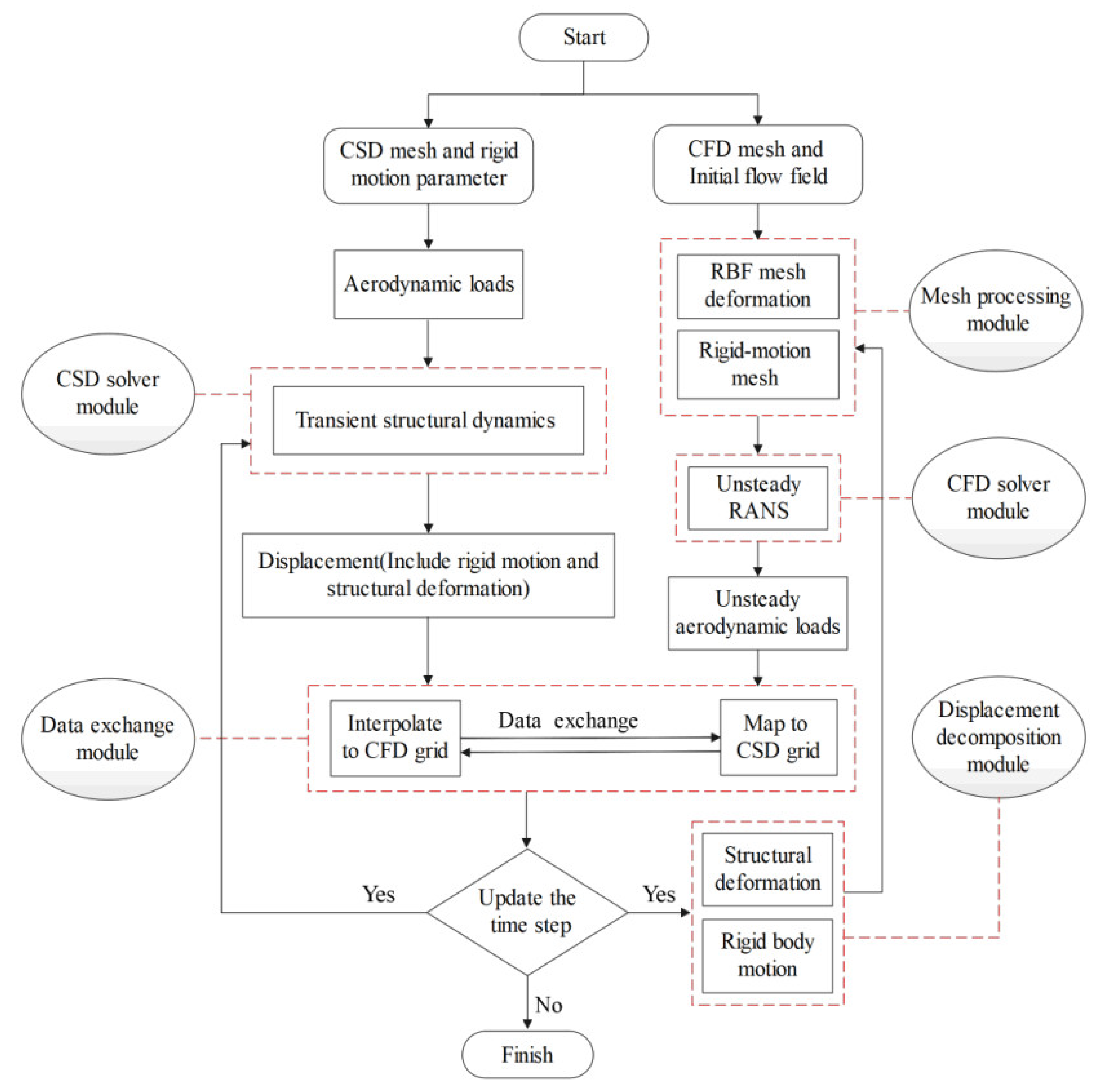
Figure 1. Flowchart of numerical method.
Aerospace 10 00646 g001
Figure 2. Generalized displacement response of the wing at different dimensionless velocities: (a) V f = 0.29 ; (b) V f = 0.32 ; (c) V f = 0.35 .
Aerospace 10 00646 g002
Figure 3. The dimensionless flutter critical velocity at different Mach numbers.
Aerospace 10 00646 g003
Figure 4. Model dimensions of the Apache.
Aerospace 10 00646 g004
Figure 5. Computational mesh for the flow calculation.
Aerospace 10 00646 g005
Figure 6. Computational mesh for structural calculation.
Aerospace 10 00646 g006
Figure 7. Variation in the total deformation with ω x at Ma=3, R e L = 1.54 × 10 7 , and α = 4 ° : (a) ω x = 0 ; (b) ω x = 5 r / s ; (c) ω x = 10 r / s .
Aerospace 10 00646 g007
Figure 8. Amplitude-frequency curves of the total deformation under different ω x at Ma = 3, R e L = 1.54 × 10 7 , and α = 4 ° : (a) ω x = 0 ; (b) ω x = 5 r / s ; (c) ω x = 10 r / s .
Aerospace 10 00646 g008aAerospace 10 00646 g008b
Figure 9. Variation in the total deformation with α at Ma = 3, R e L = 1.54 × 10 7 , and ω x = 5 r / s : (a) α = 4 ° ; (b) α = 8 ° ; (c) α = 12 ° .
Aerospace 10 00646 g009
Figure 10. Amplitude–frequency curves of the total deformation under different α at Ma = 3, R e L = 1.54 × 10 7 , and ω x = 5 r / s : (a) α = 4 ° ; (b) α = 8 ° ; (c) α = 12 ° .
Aerospace 10 00646 g010aAerospace 10 00646 g010b
Table 1. The first six natural frequencies of the Apache.
ModeFirstSecondThirdFourthFifthSixth
Frequency (Hz)21.8122.22122.59122.77314.06314.10
Damping Ratio0.0110.0120.0620.0620.1410.141
Disclaimer/Publisher’s Note: The statements, opinions and data contained in all publications are solely those of the individual author(s) and contributor(s) and not of MDPI and/or the editor(s). MDPI and/or the editor(s) disclaim responsibility for any injury to people or property resulting from any ideas, methods, instructions or products referred to in the content.