Article

Experimental Investigation of a Swirling-Oxidizer-Flow-Type Hybrid Rocket Engine Using Low-Melting-Point Thermoplastic Fuel and Oxygen

Department of Aeronautics and Astronautics, Tokyo Metropolitan University, Hino 191-0065, Japan
*
Author to whom correspondence should be addressed.
Aerospace 2023, 10(8), 713; https://doi.org/10.3390/aerospace10080713
Submission received: 7 May 2023 / Revised: 5 August 2023 / Accepted: 9 August 2023 / Published: 15 August 2023
(This article belongs to the Special Issue Hybrid Rocket Engines)

Abstract

:
Hybrid rockets are safe and inexpensive; however, boundary-layer combustion poses a problem in achieving a fuel regression rate equivalent to that of solid propellants. The fundamental combustion conditions, such as the fuel regression rate of LT421, a paraffin-based low-melting-point thermoplastic fuel, were investigated using a swirling-flow combustion method. Firing tests were conducted using the oxygen mass flow rate and burn time parameters. The LT fuel exhibited an ignition delay compared to polypropylene, and the pressure increased slowly relative to the thrust. The combustion pressure increased or remained constant with time, suggesting that the fuel regression rate was more dependent on the oxygen mass flow rate than the oxidizer mass flux. The shear force generated in the grain owing to the swirling flow caused fuel-grain separation when the oxygen mass flow rate exceeded 100 g/s. Fuel-grain separation was prevented by modifying the case geometry. The maximum fuel regression rate obtained in the tests was 4.88 mm/s at an oxygen mass flow rate of 190 g/s and mass flux of 72.4 kg/(m2s), which was four times higher than that of polypropylene at the same oxidizer mass flux. The fuel regression rate correlation was obtained using the oxygen mass-flow-rate-based parameter, although further modification was necessary to apply this correlation when the burning time was varied.

1. Introduction

Hybrid rockets generally use solid fuels and liquid or gaseous oxidizers. Combustion is heterogeneous and usually takes the form of diffusion combustion, wherein the boundary layer formed on the solid fuel surface has a dominant influence. The fuel regression rate in boundary-layer combustion is related to many physical and chemical processes, such as the boundary-layer thickness, heat transfer from the flame, and heat of melting and vaporization of the solid fuel [1]. The fuel regression rate in hybrid rocket engines is less than the burning rate of solid propellants, such as ammonium perchlorate (AP)/hydroxyl-terminated polybutadiene (HTPB)/Al composite propellants, which makes it difficult to realize a large thrust with the same propellant volume as that of solids. This is a major factor delaying the practical use of hybrid rocket engines.
In addition to the different phases of the fuel and oxidizer before combustion, diffusion combustion is less prone to explosive events, both in propellant storage and during combustion. Shimada et al. referred to hybrid rocket propulsion as an essentially non-explosive propulsion system [2]; these characteristics are difficult to realize in rockets that utilize solid or liquid propellants. One advantage of hybrid rocket engines is their safety. Virgin Galactic has continuously used hybrid rocket propulsion systems in its manned spacecraft SpaceShipTwo owing to their safety [3]. Hybrid rocket engines are also used globally for sounding rockets, student rocket projects, etc. [4,5,6], but there have been a few major accidents during their launch and handling.
Owing to the high safety features of hybrid rocket engines and the low cost resulting from the aforementioned safety features, the research and development of small hybrid rockets conducted by venture companies have been active in meeting the demand for launching nanosatellites [7,8,9,10,11]. Gilmour Space, TiSpace, and HyImpulse are developing small launch vehicles that use hybrid rocket engines to launch small satellites into low-Earth orbits. Mjolnir SpaceWorks specializes in the sale of CAMUI-type hybrid rocket motors for small launch vehicles. Letara is a venture company that developed a modular propulsion system for small satellites and spacecraft developers [12]. A more comprehensive status of hybrid rocket R&D and market observations on the use of hybrid rockets for nanosatellites and microsatellites was summarized by Mazzetti et al. [13].
Although hybrid rocket engines are characterized by safety and low cost, increasing the fuel regression rate remains an inherently important issue. Methods for increasing the fuel regression rate include the use of oxidizer injection or grain geometry to create a flow field [14,15,16] and the use of cryogenic fuels such as frozen pentane [17]. Several other methods have also been proposed. In recent years, liquefied fuels, particularly paraffin wax, have attracted considerable attention. In this case, a fuel with a low melting point that is easily liquefied is used to obtain a high fuel regression rate owing to the entrainment effect [18,19]. The effect of viscosity on the entrainment mechanism was also investigated [20,21].
The main drawback of paraffin wax fuel is its mechanical properties, and research is being conducted to improve these properties. One method of improving the mechanical properties of paraffin wax is to mix it with additive materials. The mechanical and combustion properties of paraffin-blended fuels have been investigated for various materials such as polyethylene (PE), polypropylene (PP), ethylene vinyl acetate copolymer, and stearic acid [22,23,24,25]. The effects of a wide range of additives, including metal particles, on the combustion and mechanical properties of paraffin wax were summarized in a review by Veale et al. [26]. The addition of small amounts of additives increases the strength and ductility of paraffin wax but increases the viscosity coefficient, which often results in lower fuel regression rates. Another method comprises the reinforcement of the mechanical properties of paraffin wax using additive manufacturing [27,28,29,30]. The mechanical and combustion properties of paraffin wax fuel are balanced by the reinforcement structure. Paraffin wax (FT-0070, Nippon Seiro Co. Ltd., Tokyo, Japan) was used by the authors; if a shallow crack remained during the grain molding, the fuel receded significantly from the crack during combustion, and the burned area changed irregularly [31]. These cracks were caused by the volume change of the molten paraffin wax as it solidified.
The LT fuel is a paraffin-based, low-melting-point thermoplastic fuel with excellent mechanical properties. Several LT fuels of different compositions have been developed, as listed in Table 1 [32]. All of these have slightly higher melting points than paraffin wax, and it has been confirmed that they have the same entrainment mechanism during combustion as paraffin wax [33]. LT fuels have a higher fuel regression rate than other polymer fuels, such as PE, PP, and polymethyl methacrylate (PMMA) [32,34]. The disadvantage of LT fuel is that it has a lower theoretical specific impulse than the majority of HR fuels, as shown in Figure 1. The theoretical specific impulse was calculated using the NASA program Chemical Equilibrium with Applications (CEA) [35]. The chemical composition of LT421 is C7.08132H13.41038O0.08358, based on the analytical results of Wada et al. [36]. The molar mass of LT421 is 99.96 g/mol, and the heat of formation is 1088 kJ/mol. Table 2 lists the maximum specific impulse and O/F values at combustion chamber pressure Pc = 4 MPa. The lower specific impulse of the LT fuel was due to the lower adiabatic flame temperature of the LT fuel and the higher molar mass of the burned gas. The thermal analysis of LT fuel is currently being conducted to understand its combustion mechanism [37]. The authors also conducted firing tests using LT fuel in a swirling-oxidizer-flow-type (SOFT) engine and found that cracks did not remain in the grain after the molding in the LT fuel, the grain was almost uniform, and no cracks occurred in the grain during combustion.
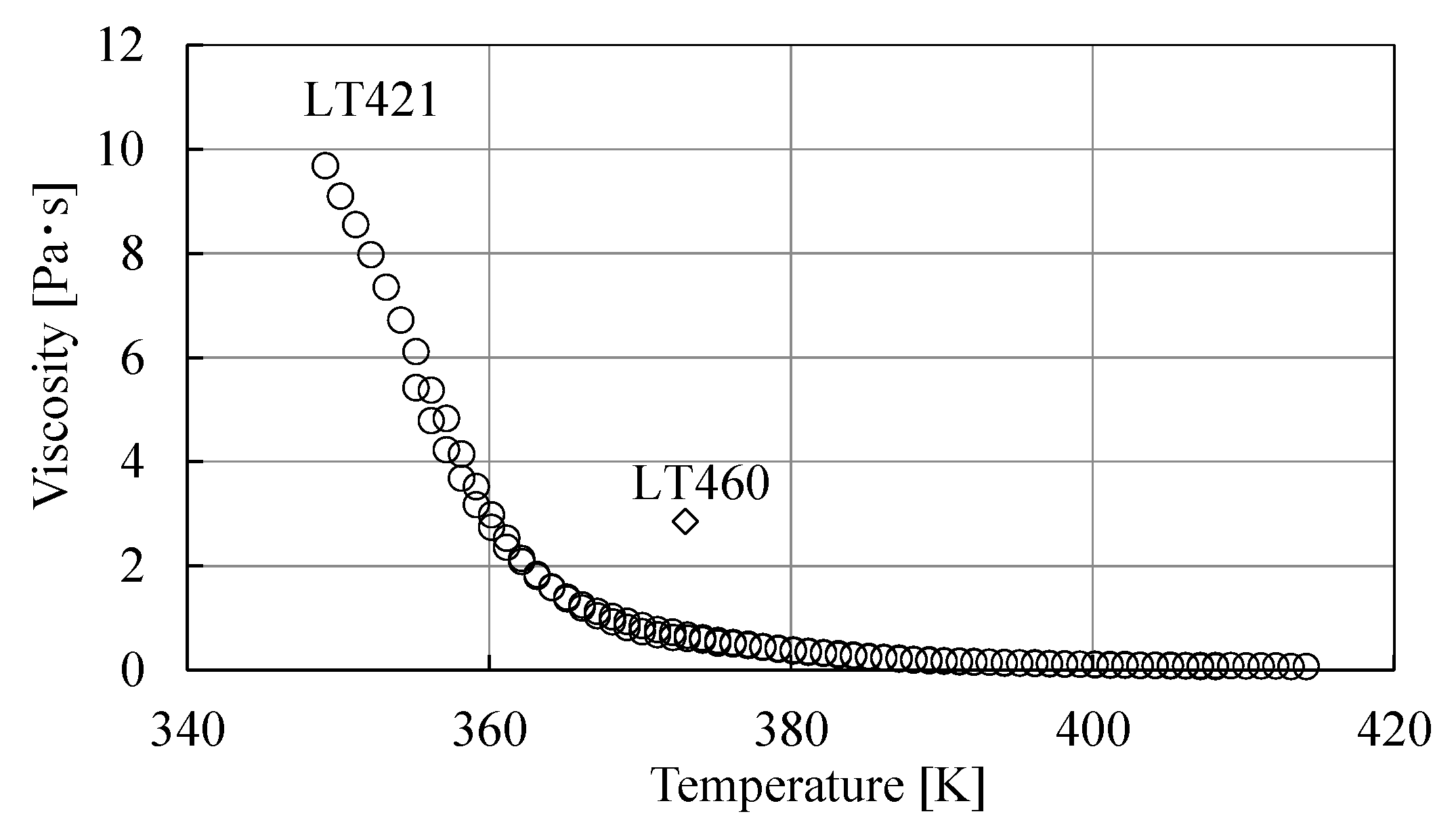
As mentioned above, although the LT fuel is inferior to many hybrid rocket fuels in terms of specific impulse, it has a high fuel regression rate and excellent mechanical properties to compensate for a specific impulse. However, a series of studies conducted by Wada, Kawabata, and Banno et al. concentrated on one of several types of LT fuel, LT460, while research on other compositions is thus still lacking [32,33,34,36,37]. In particular, LT421, which has a lower melting point and viscosity than LT460, as shown in Figure 2 [38], may have a higher fuel regression rate based on the aforementioned previous studies [18,20,21]. It is also interesting to observe the fuel regression rate that can be obtained when using a SOFT engine, which the authors have been working on. Kawabata et al. also studied the effect of swirling combustion on the regression rate of LT460 and demonstrated that the swirling flow increased the fuel regression rate by a factor of nearly three compared to the non-swirling case [34]. The maximum fuel regression rate obtained in their study was 3 mm/s at an oxidizer mass flux of 70 kg/(m2s). A higher fuel regression rate is expected for LT421 with a low viscosity.
The objective of this study was to clarify the fuel regression rate of an LT421-oxygen propellant when a swirling flow is applied. This is our first study on the application of swirl flow to LT421, and the combustion conditions were studied in detail to obtain fundamental data. First, firing tests were conducted by varying the oxygen mass flow rate, and the relationship between the obtained fuel regression rate and oxidizer mass flux is discussed. In this study, phenomena such as ignition delay of the LT fuel and grain separation due to the shear force of the oxygen-swirling flow were observed. Firing tests were conducted by varying the burn time to examine whether the fuel regression rate could be organized in terms of the oxidizer mass flux. In tests with burn time as a parameter, the temperatures of the nozzle and engine components increased as the burn time increased. The erosion and heat resistance of the components were also investigated.

2. Experimental Setup and Conditions

2.1. Experimental Setup

2.1.1. Hybrid Rocket Engine

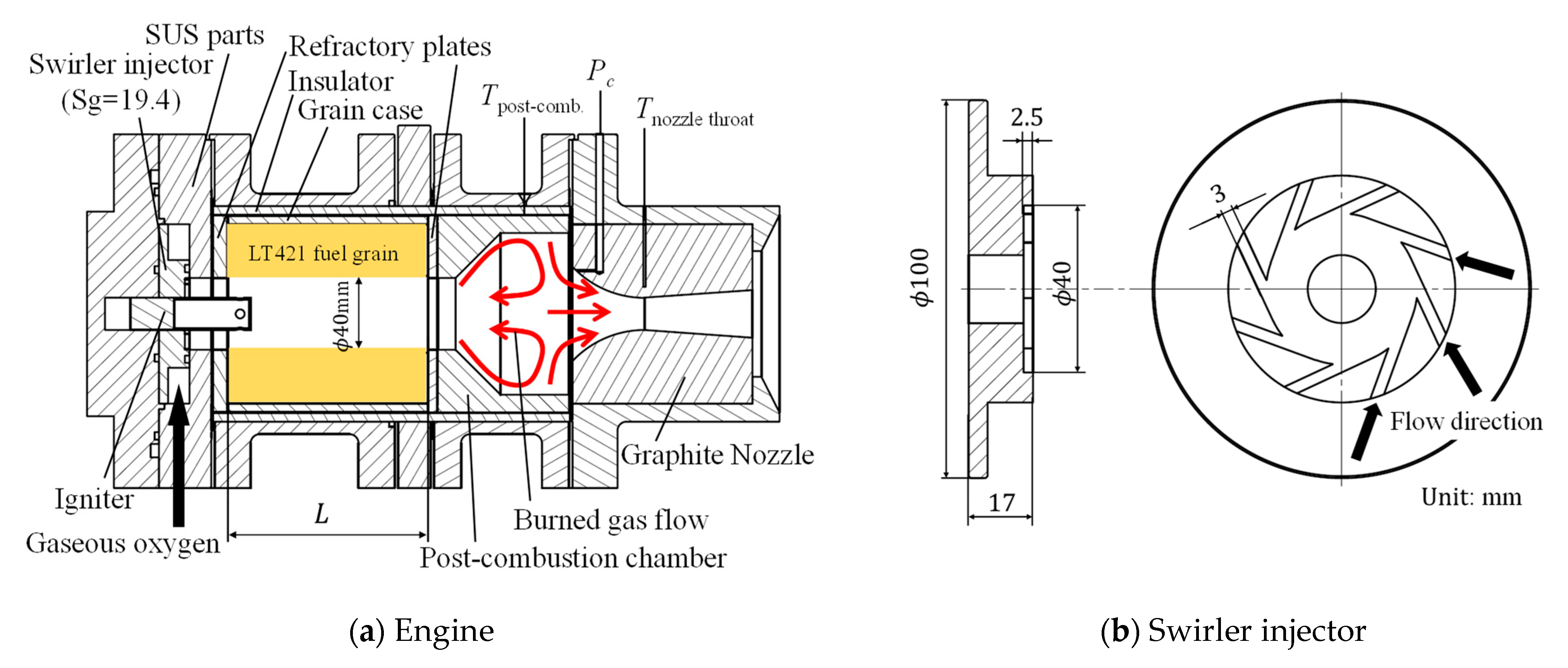
A cross-sectional view of the engine used in the experiment is presented in Figure 3a. The engine consisted of a single-port fuel grain (LT421), swirler injector, igniter, post-combustion chamber, and nozzle. The igniter was prepared using model rocket A8-3, and the burned gas was ejected orthogonally to the grain surface through four injection holes in the igniter. Figure 3b presents a swirler injector that generates a swirling flow of oxygen. The swirl number S is defined by the following equation, using both the axial flux of the angular momentum J φ and axial thrust J x [39]:
S = J φ J x r e x   ,
J φ = 0 r e x u θ r ρ u x 2 π r d r ,  
J x = 0 r e x u x ρ u x 2 π r d r + 0 r e x p 2 π r d r .  
The following equation, which omits the static pressure term, estimates the input velocity distribution in the swirler injector based on the injector geometry, thus providing a good approximation of the swirl number.
S g = J φ J x r e x   ,
J x = 2 π 0 r e x ρ u x 2 r d r .  
In this study, we refer to this as the geometrical swirl number Sg. The geometrical swirl number depends on the oxidizer mass flow rate and representative radius of the swirler, as shown in Equations (4) and (5). The Sg of the swirler injector used in this study is calculated using the following equation based on Equation (4):
S g = r e x w / 2 r e x π r e x 2 n A s l i t   .
The swirler used in this study had a representative radius of rex = 20 mm, w = 3 mm, n = 8, Ainj = 7.5 mm2, and thus, Sg = 19.4. The authors conducted several firing tests using similar swirlers with m ˙ o x up to 1.35 kg/s and r e x = 2.5–28 mm, and the fuel regression rate correlated well with Sg. The oxidizer mass flow rate and representative radius of the swirler in this study were also within the experimental range.
A post-combustion chamber was installed to improve combustion efficiency [40]. The post-combustion chamber comprised graphite. In this engine, the swirling motion of the burned gas was maintained up to the nozzle inlet because the oxygen was provided with a strong swirl [41]. The post-combustion chamber actively utilized a swirling flow and had a trailing edge to create a recirculation flow, as shown in Figure 3a. This was intended to increase the combustion efficiency by mixing the burned gas and unburned fuel.
A graphite plate was installed on the injector side of the grain as a refractory material to protect the stainless steel from high-temperature burned gas. Bakelite plates, which are thermosetting phenolic resins, were also used in these experiments. A Bakelite plate was placed between the fuel grain and post-combustion chamber as an insulator to prevent the end face of the fuel grain from melting owing to the heat from the post-combustion chamber. A cylindrical insulator fabricated using Bakelite or Lossna board, which is a heat-resistant inorganic material reinforced using glass fiber, was installed around the periphery of the fuel grain and post-combustion chamber to reduce the heat transferred to the stainless-steel case.
Three nozzle types with different throat diameters and expansion ratios were used in the experiment. The C4M nozzle had a throat diameter of 18 mm, expansion ratio of 5.4, and designed combustion chamber pressure of 4 MPa. The C1M nozzle had a throat diameter of 12 mm, an expansion ratio of 2.5, and a designed combustion chamber pressure of 1 MPa. The C1Mr nozzle had a designed combustion chamber pressure of 1 MPa and a throat diameter of 18 mm, which is similar to the case of the C4M nozzle, with an expansion ratio of 2.18. Firing tests were conducted with the combustion chamber pressure set to approximately 1 MPa. Because there were no data on the fuel regression rate of the LT421 at the beginning of the study, the oxygen mass flow rate was increased stepwise during the test. In the first test, a C1M nozzle was used; however, as the oxygen mass flow rate increased, the combustion-chamber pressure exceeded 1 MPa, and a C4M nozzle with a larger throat diameter, which was in stock and could be used immediately, was temporarily used. In this case, the nozzle was used under overexpanded conditions; however, in this study, emphasis was placed on the fuel regression rate. As the data on the regression rate increased with each firing test and the accuracy of the preliminary prediction of engine performance improved, a C1Mr nozzle with the same throat diameter as that of C4M was fabricated and used in the experiment.

2.1.2. Fuel Grain Fabrication

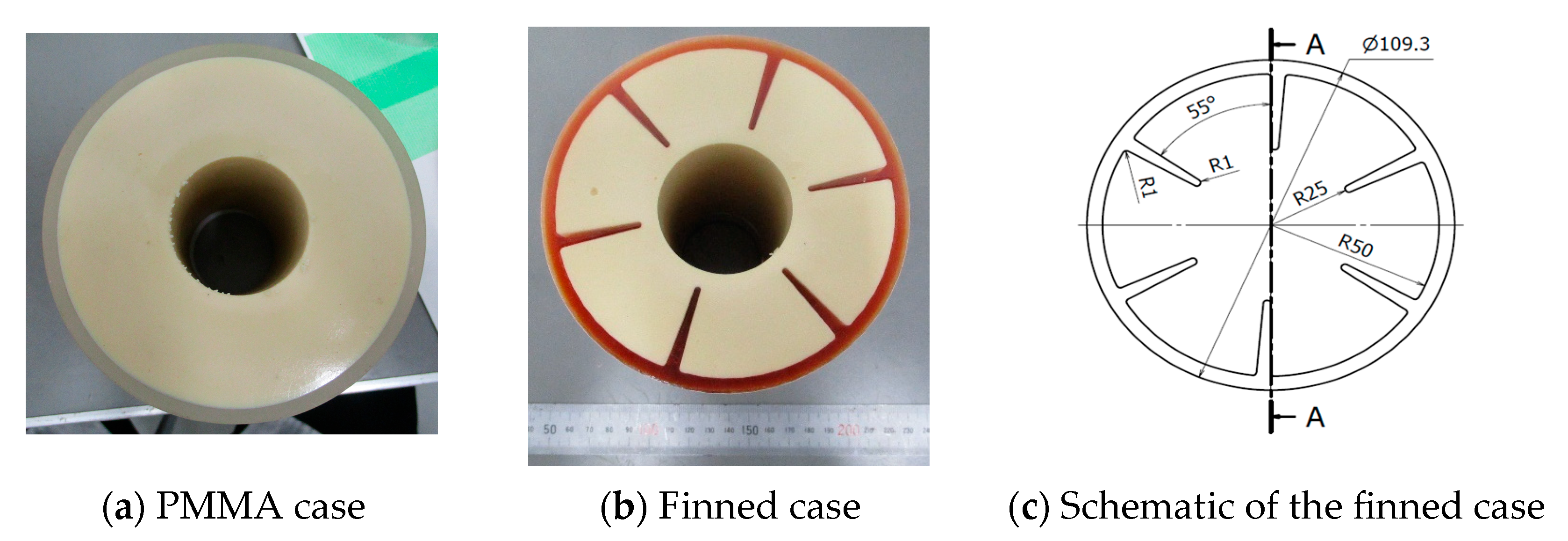
Figure 4a presents the molded LT fuel for the PMMA case. First, the LT421 was placed in a glass beaker and heated to 393 K using an electric heater. The melted fuel was then poured into a PMMA cylindrical case and solidified by natural cooling to a room temperature of 283–301 K. A round polypropylene (PP) rod was inserted at the center of the cylinder. A round PP rod was pulled out after solidification to form single-port fuel.
As described below, the LT fuel peeled off from the PMMA fuel when the oxidizer mass flow rate increased. Firing tests were conducted using a finned case fabricated using a 3D printer. Figure 4b presents the LT fuel molded into a finned case. The molding method was the same as that used for the PMMA case, and the LT Fuel was poured into the finned case. A schematic of the finned case is presented in Figure 4c. The main objective of this study was to prevent grain separation. Therefore, the case shape was simple. However, as there are some studies in which the shape of the case induces a flow that is effective in increasing the regression rate [42], we plan to study the shape of this case in the future. The material used was AR-H1, a photocurable resin mainly comprising acrylic monomers, and a Keyence AGILISTA-3200 was used for the fabrication. The cause of the fuel grain separation, in this case, is considered to be the shear force of the swirling oxygen flow acting on the inner surface of the grain. Hence, the fins protruded into the cylinder in six circumferential directions to support the circumferential forces acting on the grains. The fin shape was determined to increase the LT fuel-filling rate inside the case. The mass-filling ratio of the LT fuel in the designed finned case is 94.4 mass% compared to that in the PMMA case without fins.

2.1.3. Engine Test Facility

An overview of the experimental apparatus used is presented in Figure 5. The engine was fixed to the thrust stand, and oxygen was supplied from the cylinder. To suppress combustion, nitrogen was supplied to the engine through the same piping as that used for oxygen. An electric spark was used to ignite the igniter installed inside the engine, and an electric wire was connected to the igniter through the nozzle outlet.
The oxygen supply pressure was set to choke the flow such that the mass flow rate was not subject to fluctuations in the combustion chamber pressure. The oxygen mass flow rate under choke conditions is expressed as follows:
m ˙ o x = C d A t P u R o x T u κ 2 κ + 1 κ + 1 κ 1   .
During the experiments, the orifice diameter and oxygen supply pressure were adjusted to achieve the specified mass flow rate. The flow coefficient was determined for each orifice type through calibration experiments of the oxygen gas flow rate under choked conditions.
The combustion chamber pressure was measured at the nozzle inlet, where the burned gas flow stagnated. The oxygen mass flow rate was measured using pressure and temperature sensors installed upstream of the orifice. The wall temperature of the post-combustion chamber was measured using a K-type sheathed thermocouple with an outer diameter of 1 mm installed on the outer wall. The nozzle-throat wall temperature was measured 6.3 mm from the inner surface of the throat using a K-type sheathed thermocouple with an outer diameter of 1 mm. The thrust force was measured using a load cell.
The pressure, thrust, and temperature were recorded using a data logger. The sampling rate was set as 1 kHz. However, the response time of the thermocouples was slower than the sampling rate by approximately 10 Hz. The pressure sensor used for the combustion chamber pressure measurement had a frequency response of the order of 10 kHz, but the sampling rate of the data logger was a rate-limiting process, and its frequency response was less than 500 Hz according to the sampling theorem. The pressure sensors used to evaluate the oxygen mass flow rate were low-pass filtered at a threshold of 300 Hz to increase the signal-to-noise ratio. The load cell output was low-pass-filtered at a threshold of 300 Hz.
The load cell output was calibrated before each firing test after the engine and piping were installed. The maximum uncertainty of the measured values was ±5 N. The experimental results confirmed that the thrust stand experienced a natural vibration of 15–16 Hz after the engine was installed.

2.2. Data Analysis and Experimental Condition

2.2.1. Setting Targets for Equivalence Ratios

As fundamental data for setting the experimental conditions, the specific impulse of LT421-oxygen for the equivalence ratio was calculated using NASA CEA at combustion chamber pressures of 1 and 4 MPa. Figure 6 presents the calculation results. The equivalence ratio with the highest Isp varied with the combustion-chamber pressure. At Pc = 1 MPa, Isp peaked at an equivalence ratio of approximately 1.3. As pressure increases, the equivalence ratio value at which Isp maximizes decreases with φ = 1.2 at 4 MPa. The experimental conditions were set based on these data.

2.2.2. Regression Rate and Oxidizer Mass Flux

The oxidizer mass flux is expressed by the following equation and varies with the oxygen mass flow rate and time-averaged port diameter:
G o x = 4 m ˙ o x π d a v e 2   ,
The time-averaged port diameter is defined by the following equation, and the port diameter at the end of combustion varies with the burn time [43]:
d a v e = d i + d f 2   ,
d f = d i 2 + 4 w f π L ρ f .
The time-averaged fuel regression rate across the grains (referred to as the fuel regression rate in this study) was calculated using the following equation:
r ˙ = d f d i 2 t b     .

2.2.3. Experimental Conditions

Firing tests were conducted using the oxygen mass flow rate and burn time as parameters for investigating the effect of the oxidizer mass flux on the fuel regression rate. The experimental conditions and target values for each firing test are listed in Table 3.
When the oxygen mass flow rate was varied, the target burn time was set to a constant of 4 s. The firing tests were initiated at a low oxygen mass flow rate, and its value was increased in steps. For each test, the correlation formula of the fuel regression rate for predicting the engine performance was modified, and the conditions were set sequentially to achieve an equivalence ratio with a high specific impulse at a combustion chamber pressure of approximately 1 MPa. Therefore, the number of nozzles used in each test was varied. In particular, the C1Mr nozzle caused a large erosion at #719, which is described later. To indicate the history of use of this nozzle, the order in which it was used is indicated by a number such as C1Mr-1. In addition, the finned cases were used under conditions #715 and #719 because fuel grain separation occurred frequently in the PMMA case when the oxygen mass flow rate was 100 g/s or greater.
When the burn time was varied, the oxygen mass flow rate and grain shape remained constant. At a burn time of 13 s at #714, a fuel grain with a thickness of 30 mm was expected to burn out based on the fuel regression rate correlation at an oxygen mass flow rate of 80 g/s. To validate this prediction, a firing test #717 with a longer burn time of 16 s was conducted. All the nozzles used in this series of firing tests were C1Mr. Bakelite was used as insulation between the PMMA and stainless-steel cases. The heat insulator plate on the swirler injector side of the grain was changed from graphite to Bakelite only for #711.

2.2.4. Data Analysis

The relative error of each value based on the experimental measurements was evaluated using the following equations [43]:
R = d f d i   ,
E d f = E d i R 2 + 0.5 1 1 R 2 2 E w f 2 + E ρ f 2 + E L 2 2 1 / 2   ,
E r ˙ = R R 1 E d f 2 + 1 R 1 E d i 2 + E t b 2 1 / 2 ,
E G o x = 2 R R 1 E d f 2 + 2 R 1 E d i 2 + E m ˙ o x 2 1 / 2 ,
The following values were used for each firing test: E w f = 0.062, E d i = 0.008, E ρ f = 0.01, E L = 0.005, and E m ˙ o x = 0.025.
The C* efficiency can be expressed by the following equation, assuming a uniform pressure field in the engine:
η C C e x p C t h = P c , e x p A t m ˙ e x p / P c , t h A t m ˙ t h   ,
Assuming that the experimental time-averaged propellant mass flow rate is equal to the theoretical mass flow rate, the C* efficiency can be determined from the ratio of the experimental and theoretical pressures [44]:
η C C e x p C t h = P c , e x p P c , t h   ,
The theoretical pressure was calculated using the following equation, with the values calculated using NASA CEA, the experimental time-averaged equivalence ratio, and the nozzle throat area:
m ˙ t h = P c , t h A t κ M w R 0 T c , t h 2 κ + 1 κ + 1 κ 1   .

3. Experimental Results and Discussion

3.1. Effect of Oxygen Mass Flow Rate on Fuel Regression Rate

3.1.1. Typical Combustion Condition

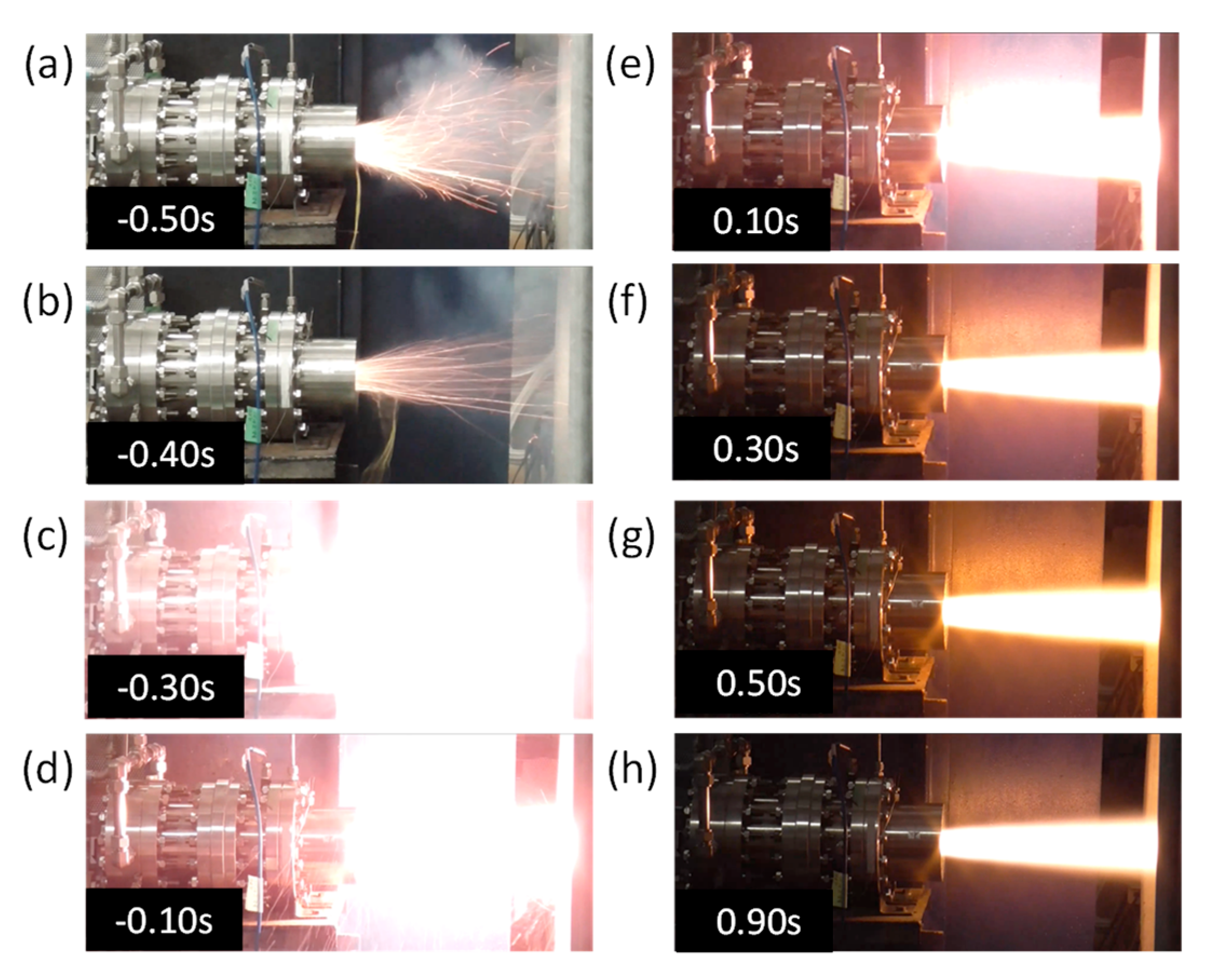
Figure 7 presents the time histories of the oxygen mass flow rate, combustion chamber pressure, and thrust for #701, and Figure 8 presents the appearance of the exhaust plume during firing. The burn time was defined as the time at which the combustion chamber pressure exceeded 80% of the time-averaged value. This was determined via iterative calculations to determine the average pressure value in the section from rise to fall, while using the start and end times of combustion as parameters, and to determine the section with the longest burn time. It should be noted that the burn time presented in the graph differs from the programmed sequence times for the ignition and oxygen supply. The oxygen mass flow rate was maintained at a constant during the combustion because of the choke. The ignition of the igniter occurs at approximately −0.5 s. After the igniter ignition, the combustion chamber pressure increased more slowly than the thrust. Figure 8c shows that 0.2 s after the ignition of the igniter, a strong luminescence appeared at the outlet of the nozzle, which is an indication that the grain was ignited. The emission of the exhaust flame was subsequently weakened until 0.1 s, and from 0.3 s, the shape of the exhaust plume and its emission became static. During this time, it is considered that the recirculation flow of the burned gas in the post-combustion chamber was insufficiently formed, and much of the molten fuel was discharged unburned; therefore, the increase in the combustion chamber pressure was thought to be slower than the thrust. Although it contained a large amount of unburned fuel, the thrust increased more steeply than the combustion chamber pressure owing to the large mass flow exiting the nozzle. This difference between the combustion chamber pressure and thrust caused by the ignition delay of the grain was observed in many cases in this study, although the degree of difference varied from test to test. The time variations in the combustion chamber pressure and thrust did not coincide until approximately 1 s after ignition. The pressure stabilized after 1 s. In this study, the combustion state was transient, with significant changes from ignition to approximately 2 s. In addition, the pressure increased slowly after 2 s with an increase in the burn time. The thrust also increased in response to an increase in the pressure.
For the same engine with PP fuel using a similar swirler injector and ignitor, the increases in the combustion chamber pressure and thrust were in good agreement, as shown in Figure 9. In the previous firing tests, the ignition delay of the fuel grain was not a problem when PP was used in the SOFT engine. In a study conducted by Merotto et al., which compared the combustion conditions of HTPB and paraffin-based fuels, it was found that the transient condition was longer before the combustion condition settled for the paraffin-based fuel, which is similar to the case of the present study [45]. Hence, it is unlikely that the engine configuration was the cause of this, but rather a phenomenon unique to LT421, which has a low melting point.
In this study, it is highly likely that the fuel regression rate depends on the oxygen mass flow rate rather than the oxidizer mass flux and that the effect of the port diameter change is negligible.
r ˙ = F m ˙ o x F m ˙ o x ,   d a v e   ,
Therefore, the fuel mass flow rate is proportional to the port diameter according to the following equation:
m ˙ f = r ˙ ρ f π d L d   .
Hence, the fuel mass flow rate was considered to have increased with time. Because the oxygen mass flow rate was constant in this test, the propellant mass flow rate increased; thus, the combustion chamber pressure increased with time.
Small oscillations were observed in the thrust. As shown in Figure 10a, these oscillations appeared even when the thrust magnitude changed. To investigate the cause of this oscillation, the engine was placed on a thrust stand, as in the firing test, and gas supply piping was connected to the engine. The right end of the thrust stand, shown in Figure 5, was struck with a hammer to apply the same excitation force as the thrust to the load cell. The results thus obtained are presented in Figure 10b. Figure 10c presents an enlarged view of the thrust history of #715. The oscillation frequencies of the two were approximately 15–16 Hz, which is in good agreement. Therefore, the oscillation in the thrust history is attributed to the natural frequency of the thrust stand.

3.1.2. Fuel Grain Separation by Shear Force of Swirling Flow

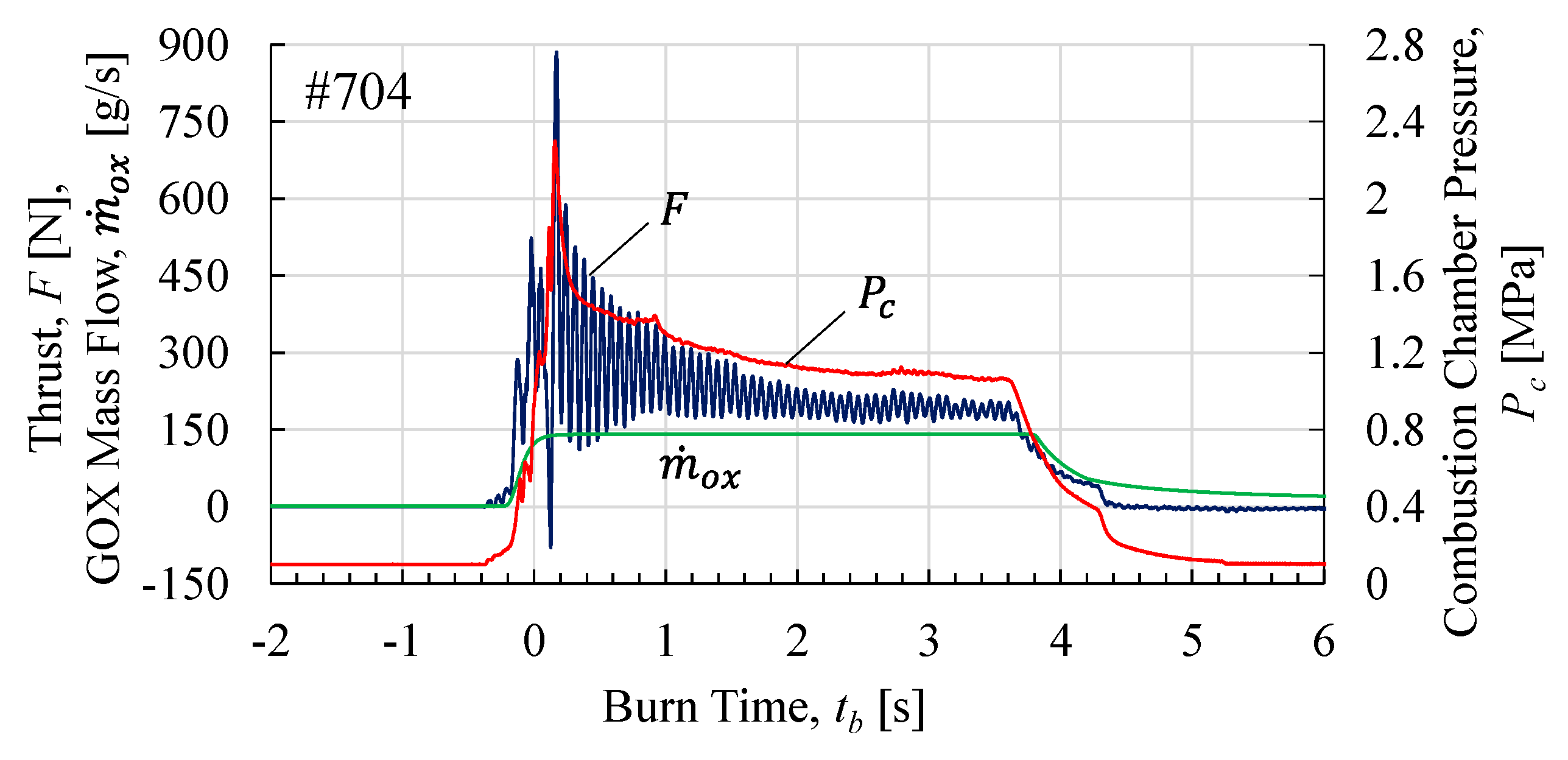
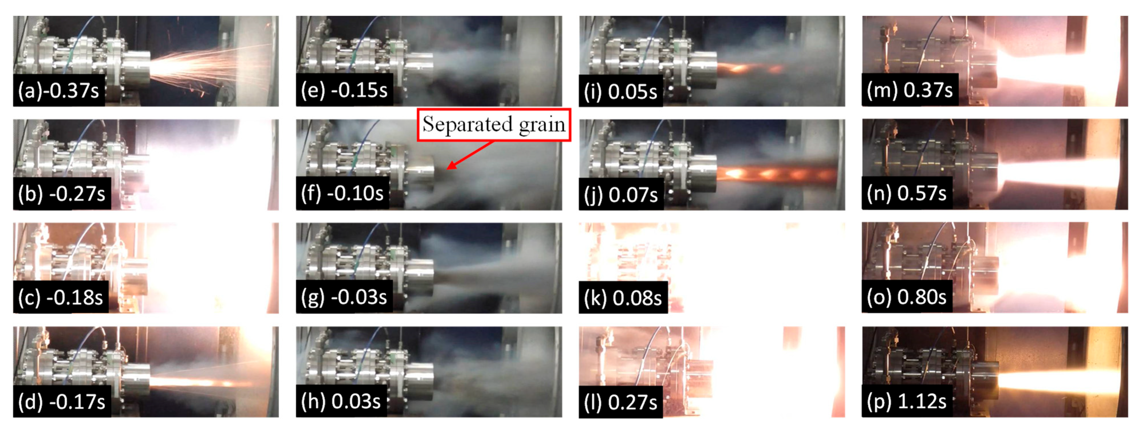
When the oxygen mass flow rate was increased to 100 g/s or greater, the LT fuel grain often separated from the PMMA case immediately after the combustion started. When this event occurs, the unburned grains are cleanly separated from the inner surface of the PMMA case, passed through the nozzle, and discharged outside the engine. Figure 11 and Figure 12 present the data and appearance of the exhaust plume at the nozzle outlet for the grain-separation event for #704, respectively. The combustion chamber pressure increased as the grain ignited 0.1 s after the igniter ignited at −0.37 s. However, under the present conditions, the fuel grain is considered to have separated from the case at −0.18 s, and the exhaust plume became small at −0.17 s, and thereafter until 0.03 s, only a large amount of soot was visible, while the exhaust flame was not visible. At −0.10 s, the separated grain was observed as a black shadow ejected from the nozzle. Video images showed that the separated grain was ejected from the nozzle from −0.10 s to 0.03 s. During this time, combustion continued in the engine, and while the combustion chamber pressure increased owing to the grain partially blocking the nozzle throat, a sudden decrease in thrust was observed. After the grains were discharged, an exhaust flame was observed again at 0.05 s. Simultaneously, the unburned gas remaining inside the engine suddenly erupted, causing a pressure spike owing to the rapid combustion at 0.08 s. Subsequently, the exhaust plume gradually stabilized, and the engine transitioned to stable combustion; however, at 0.80 s, the exhaust plume momentarily became larger, and a change in the combustion chamber pressure was observed.
Such grain separation did not always occur at oxygen mass flow rates of 100 g/s or greater, and in some cases, such as #701, normal combustion occurred even at 107.0 g/s. However, grain separation also occurred in the tests at 107.9 (#698), 111.9 (#707), and 140.8 (#704) g/s, and approximately 100 g/s was considered as the reference value for the occurrence of grain separation.
To confirm the adhesive strength between the PMMA case and LT421 fuel, an LT fuel with a thickness of 30 mm, which is the same thickness as that in the firing test presented in Figure 13, was prepared by sandwiching it between two PMMA plates. The LT fuel specimen was rectangular, 100 mm long, 50 mm wide, and 30 mm thick. The length of the adhesive surface of the LT fuel with the PMMA plate was almost identical to that in the firing test case. As shown in Figure 13, when one of the PMMA plates was fixed, and a load was applied to the other plate, separation began to occur between the LT fuel and PMMA plate when a shear stress of approximately 5 kPa was applied. Subsequently, the shear stress of the swirling flow acting on the inner surface of the LT fuel grains during the early stages of combustion was examined. The model is illustrated in Figure 14. The geometric swirl number in this engine can be approximated using the axial and tangential velocities as follows:
S g u θ u x   ,
The velocity of the burned gas is expressed as
u = u x 2 + u θ 2 = m ˙ p ρ b S p m ˙ o x ρ b S p   ,
Here, the propellant mass flow rate is assumed to be equal to the oxygen mass flow rate because grain separation occurred in the early stage of combustion. Using Equations (21) and (22), the tangential velocity of the burned gas was
u θ = m ˙ o x ρ b S p 1 1 + 1 S g 2   ,
Assuming that the molten layer of the LT fuel flows at the same velocity as the burned gas, the shear stress produced can be expressed using the thickness and viscosity of the molten layer as follows:
τ w = μ u y μ u θ y   ,
When we used the calculation following values of ρ b = 0.9348 kg/m2, S p = 0.0099 m2, y = 1 mm, and μ = 0.668 Pa·s, the tangential velocity for #704, for which m ˙ o x = 0.141 kg/s, was 15.2 m/s and the shear stress was estimated to be 10.2 kPa. Although an approximate estimate was obtained using the same values, the oxygen mass flow rate at which the shear stress reached 5 kPa was 69 g/s. These calculations were considered reasonable with respect to the experimental results. Fuel separation was thought to be caused by shear stress from the swirling flow. Considering this result, firing tests #715 and #719 were conducted using the finned cases.

3.1.3. Combustion Condition with Finned Case

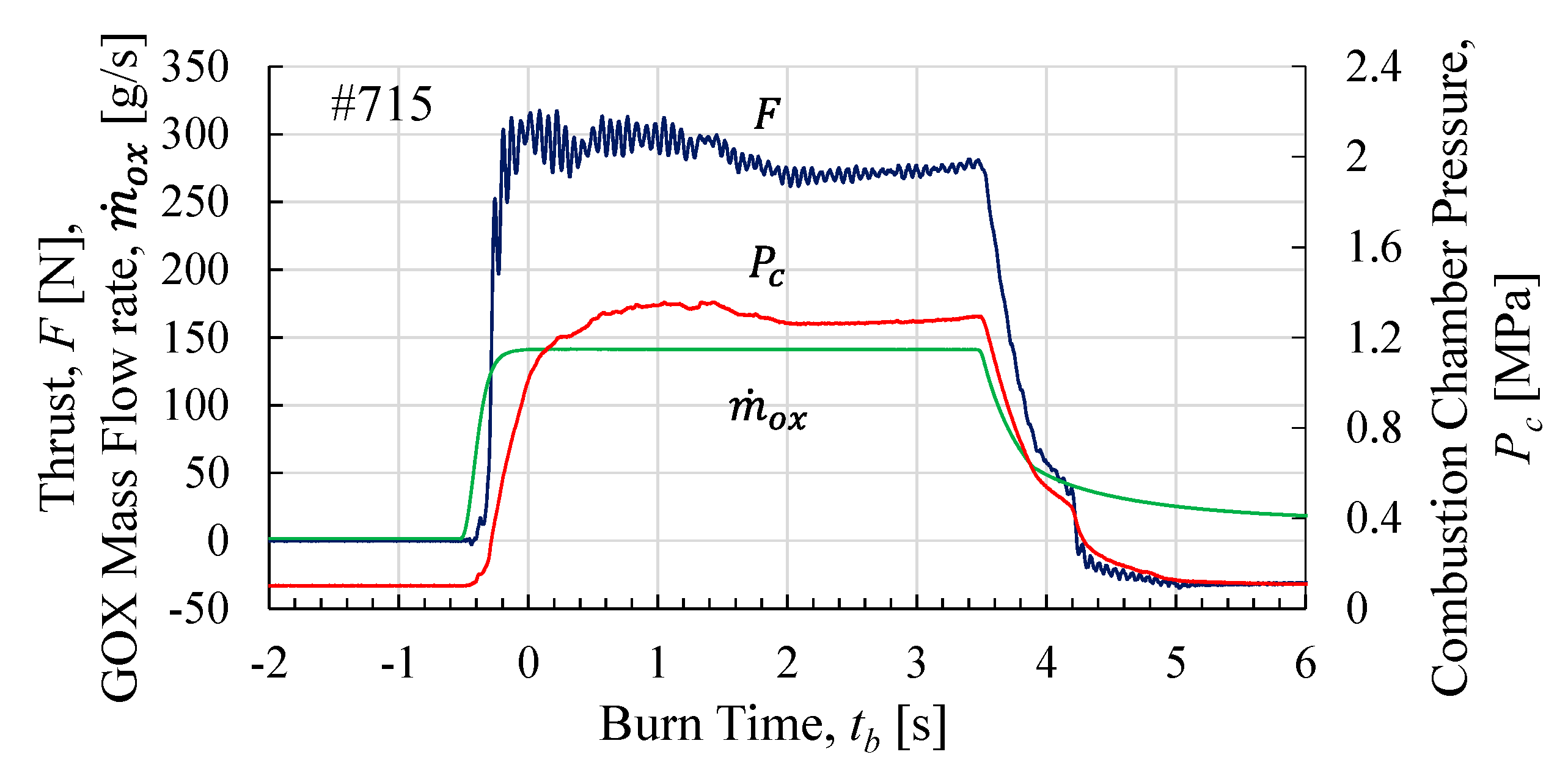
Figure 15 presents the data for #715. The fins were effective in preventing fuel separation even when the oxygen mass flow rate was increased to over 100 g/s. However, because the fins mainly comprised acrylic resin, which burns more slowly than LT fuel, there was a concern that the fins would remain after the LT fuel was burned and consumed, thus impeding the swirling flow. The data showed that the combustion chamber pressure and thrust increased as the oxygen mass flow rate increased compared with those of #701. The combustion characteristics observed before the case change, such as the slow increase in the combustion-chamber pressure relative to the thrust and the transient condition of the fluctuating combustion-chamber pressure and thrust for approximately 2 s after ignition, were also observed when the finned case was used, and the time history was similar to that presented in Figure 7. Figure 16 presents the fuel grains after the firing test for #715. Although the fins receded more slowly than in the LT fuel, the burned shape was similar to that of the LT fuel. Consequently, there was no significant change in the flow field owing to the fins. During the test, no erosion occurred at the nozzle.
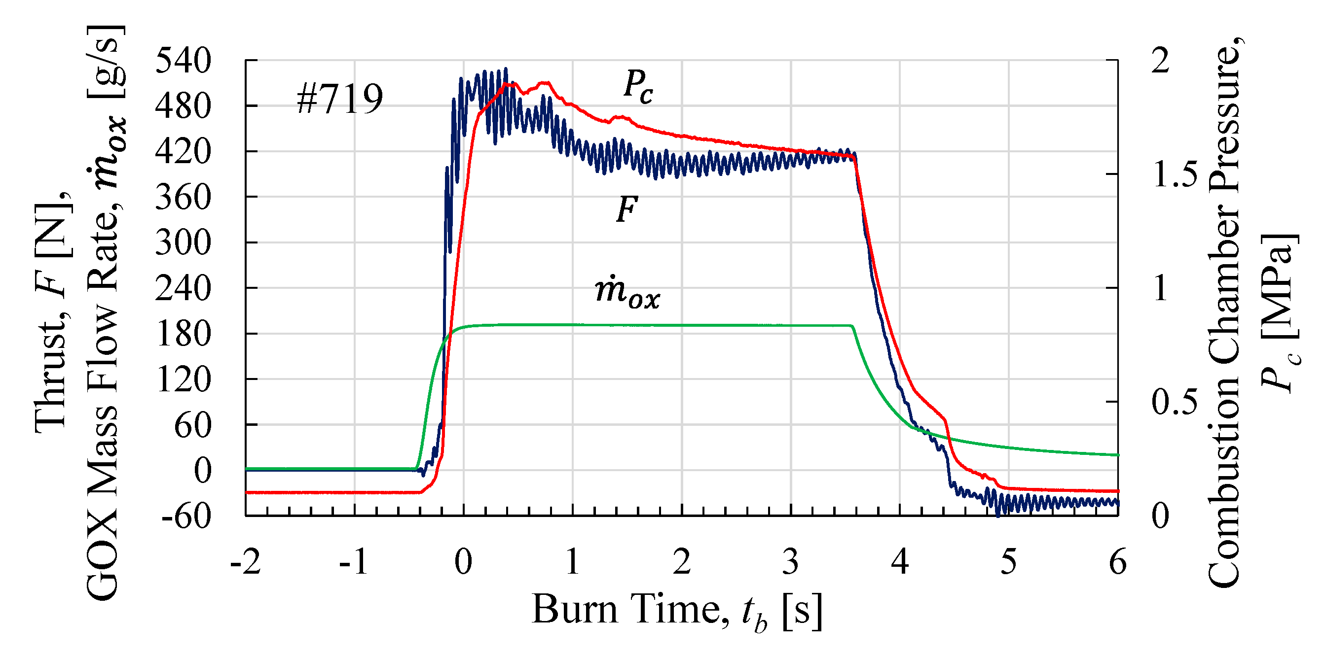
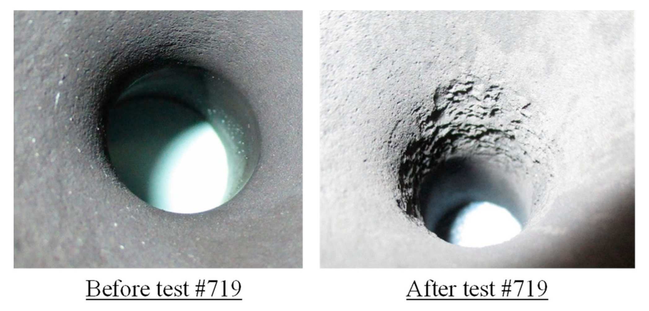
Figure 17 presents the data for #719. The pressure decreased gradually during combustion, and the thrust also decreased with pressure from approximately 0.5 s to 1.5 s. Observations of the nozzle after the test showed that erosion occurred in the nozzle throat. Figure 18 shows photographs of the nozzle throat before and after combustion, wherein the erosion was particularly pronounced. The same nozzle was used in the firing tests described in Section 3.2, where the burn time was a parameter. However, the throat diameter did not change during the firing tests. For #719, a particularly large depression circumferentially developed in the throat at the nozzle inlet side, and the throat diameter increased from 18 mm to 19.6 mm. Although the combustion chamber pressure decreased during combustion owing to the nozzle throat erosion, the thrust remained constant or increased slowly after approximately 2 s. This is because the nozzle used under these conditions expanded properly at Pc = 1 MPa. As the combustion chamber pressure decreased, it approached the design combustion chamber pressure. As a result, the exhaust velocity at the nozzle outlet increased, and the thrust was maintained.

3.1.4. Time-Averaged Engine Performance and Fuel Regression Rate Correlation

Table 4 lists the time-averaged results of the firing tests. Except in the case of #688, the equivalence ratios did not deviate significantly from the theoretical optimum values. As mentioned in Section 2.1.1, the lack of data on the fuel regression rate of LT421 at the beginning of this study made it impossible to predict the engine performance in advance and prepare a nozzle that would expand optimally to match the combustion chamber pressure. Therefore, in the first test (#688), the equivalence ratio deviated significantly from the optimum value for the maximum specific impulse. In addition, as listed in Table 4, the nozzles used in each test did not reach the optimum expansion conditions. Therefore, Isp was much lower than the theoretical value and is not listed in the table. The tests were conducted with a stepwise increase in the Gox activity as the oxygen mass flow rate increased. The fuel regression rate increased with Gox; however, the relationship between the two is discussed later. The C* efficiency was very good, and in some cases, the C* efficiency exceeded one. This is because the C* efficiency was calculated using Equation (17), which assumes a uniform pressure field in the combustion chamber, as described in Section 2.2.4. In contrast, swirling-flow-type engines create a large pressure gradient in the combustion chamber owing to the swirling flow [46]. Past evaluations of the authors’ engine have estimated that the pressure near the wall is several percent higher than that at the center of the combustion chamber [47]. Because the combustion chamber pressure was measured at the periphery of the nozzle inlet in this study, it is possible that, in this study, the experimental value was evaluated to be a few percent higher. The exhaust plume at the nozzle outlet was observed to swirl owing to the short engine length, and it is highly possible that the swirling flow also affected the pressure. Therefore, the main reason for the C* efficiency being greater than one is that the combustion chamber pressure in the test was estimated to be several percent higher. In addition, the time-averaged equivalence ratio was used to estimate the theoretical combustion chamber pressure; however, in reality, the equivalence ratio was likely to change during combustion, which also affects the C* efficiency as an error factor.
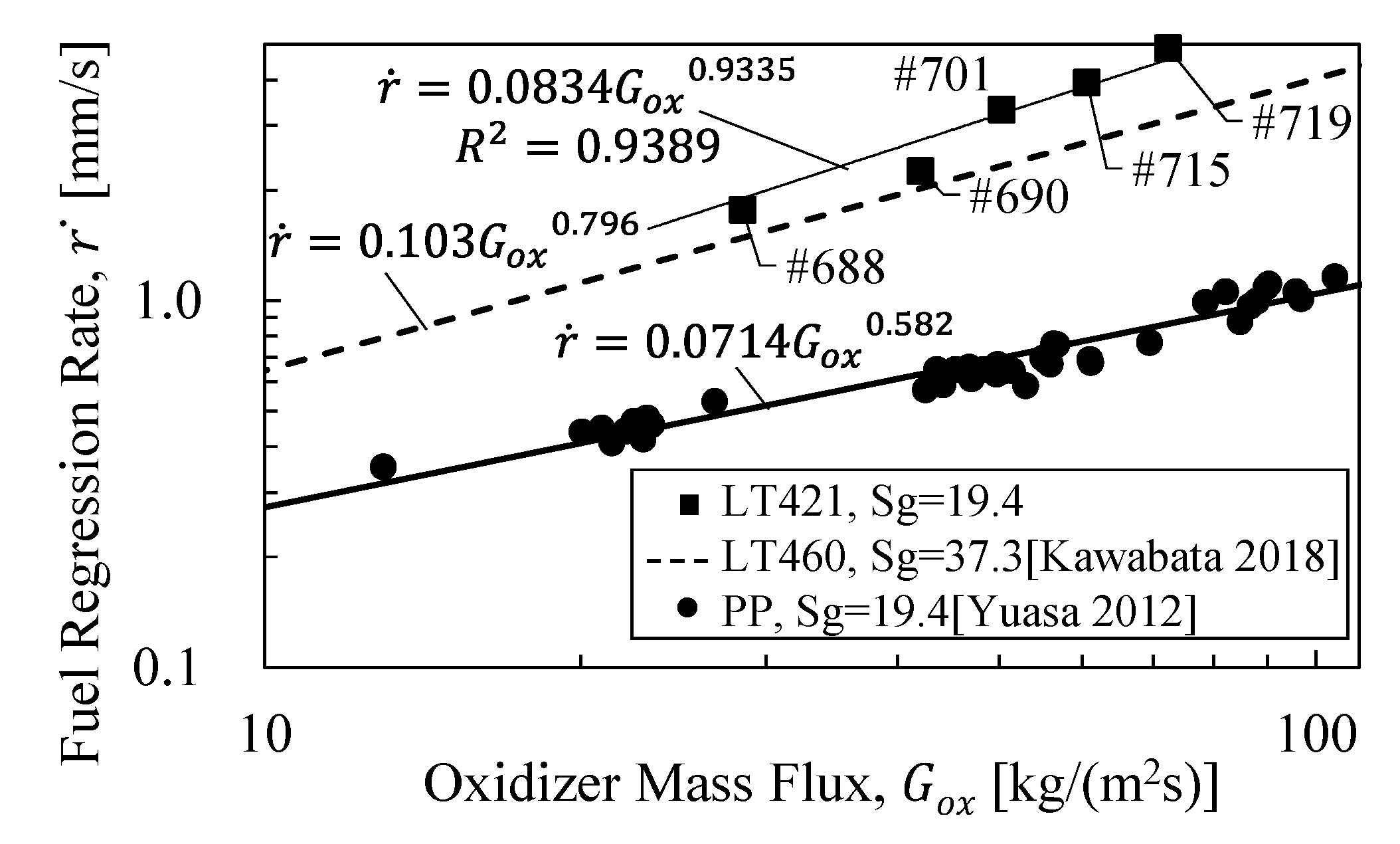
Figure 19 presents the fuel regression rate based on the oxidizer mass flux. In addition to the data obtained from these tests, data previously obtained by the authors for PP fuel [48] and data obtained by Kawabata et al. for LT460 fuel in a swirling-flow-type engine [34] are presented. The fuel regression rate of LT421 was fairly correlated with Gox, except in the case of #690. The data-fitted correlation formula was r ˙ = 0.0834 G o x 0.9335 . Although the data for #690 were different from the other test data, the reason for this was unclear. Compared with the fuel regression rate of the PP fuel with the same Sg = 19.4 in a similar engine, the fuel regression rate of LT421 was more than four times higher than that of the PP fuel. The fuel regression rate was also higher for LT421 than for LT460 for the same Gox. This was owing to the lower viscosity of LT421 than that of LT460.
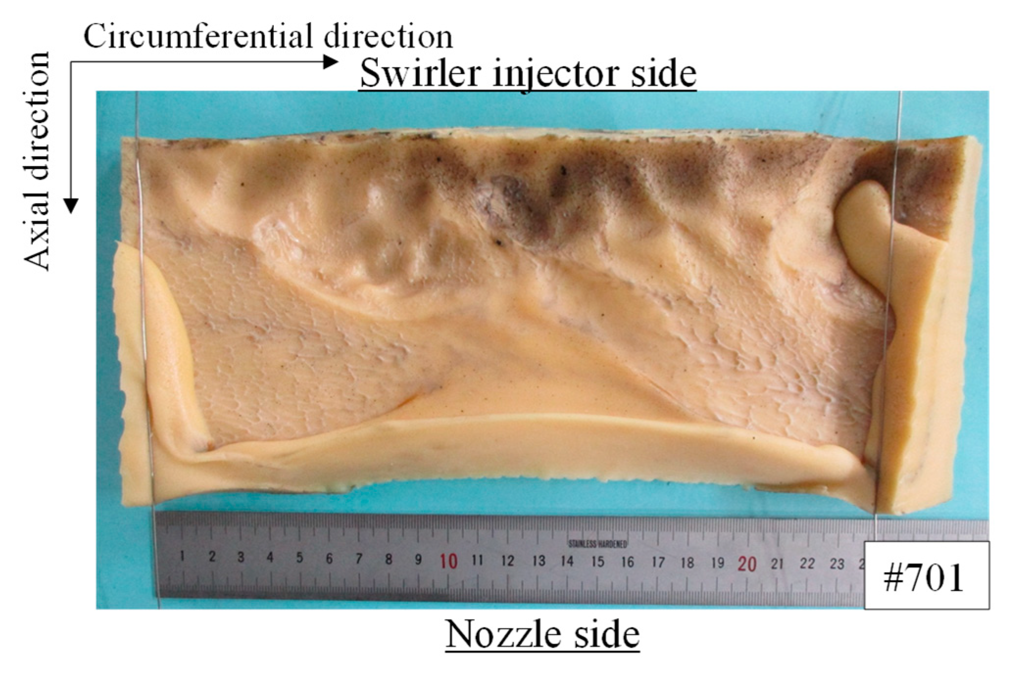
Figure 20 presents the burned surface of the grain after the test conducted for #701. The upper and lower parts of the photograph show the swirler injector and nozzle sides, respectively. The left and right ends correspond to the lower surfaces of the grain when installed in the engine, and the central part corresponds to the upper surface of the grain. A large circumferential indentation was observed on the injector side. Fifty millimeters downstream of the leading edge of the grain, below the large depression, there was a pattern of small rings arranged from left to right. This pattern is related to the eddy scale of turbulence generated during combustion. The direction of the ring pattern was consistent with that of the oxygen flow from the swirler injector. A similar pattern was observed in a study conducted by Kawabata et al. [34]. The ring pattern at the center of the fuel grain was absent, and the reason for this remains unclear.
The authors proposed the following fuel regression rate correlations for the SOFT hybrid rocket engines [49]:
r ˙ f = 5.63 × 10 5 m ˙ o x / A i n j μ o x S g 0.541         x = 0 ~ L f ,
r ˙ r = 2.33 × 10 3 m ˙ o x + m ˙ f A a v e d a v e d i S g 0.729   x = L f ~ L   ,
L f = 0.328 × d i 3 4 · m ˙ o x μ o x · S g 1 4   .
In the leading-edge region, the swirling oxygen acts as a wall jet and dominates the boundary layer thickness and, thus, the fuel regression rate. In the rear region, wherein the turbulent boundary layer was well-developed, the propellant mass flux dominates the boundary layer thickness and fuel regression rate. In this study, we examined whether these correlations could be applied to LT fuels. The lengths of the leading-edge regions are summarized in Table 5. It was found that, for the range of oxygen mass flow rates in these tests, the fuel grain length was approximately equal to Lf, and the leading-edge correlation of Equation (25) could be applied over the entire length of the grain. Figure 21 presents the relationship between the regression rate and the leading-edge parameter. In the regression rate correlation, the exponent for the parameter was the same as that for the PP fuel. It can be observed that the data for the LT fuel were also in good agreement with the correlation equation for the leading edge. This result was consistent with the earlier discussion of the pressure history in Figure 7, wherein the fuel regression rate was considered to be more strongly related to the oxygen mass flow rate than to the mass flux. In this study, the fuel grain length was short, and the oxidizer swirling flow strongly affected the entire grain length. However, as the engine is scaled up in the future, the grain length will increase, and correlation Equation (26) for the rear region, which depends on the propellant mass flux, will also become important. This will be a subject of future research.

3.2. Effect of Burn Time on Fuel Regression Rate

3.2.1. Combustion Conditions and Fuel Regression Rate

To investigate the fuel regression rate of LT421–oxygen, the oxidizer mass flux was varied with the burn time rather than with the oxygen mass flow rate. The objective of the firing tests was also to investigate the presence of erosion in the post-combustion chamber and nozzle. Fundamental data on the graphite used in the post-combustion chamber and nozzle are available in [50], and the data on erosion in hybrid rocket motors are available in [51,52].
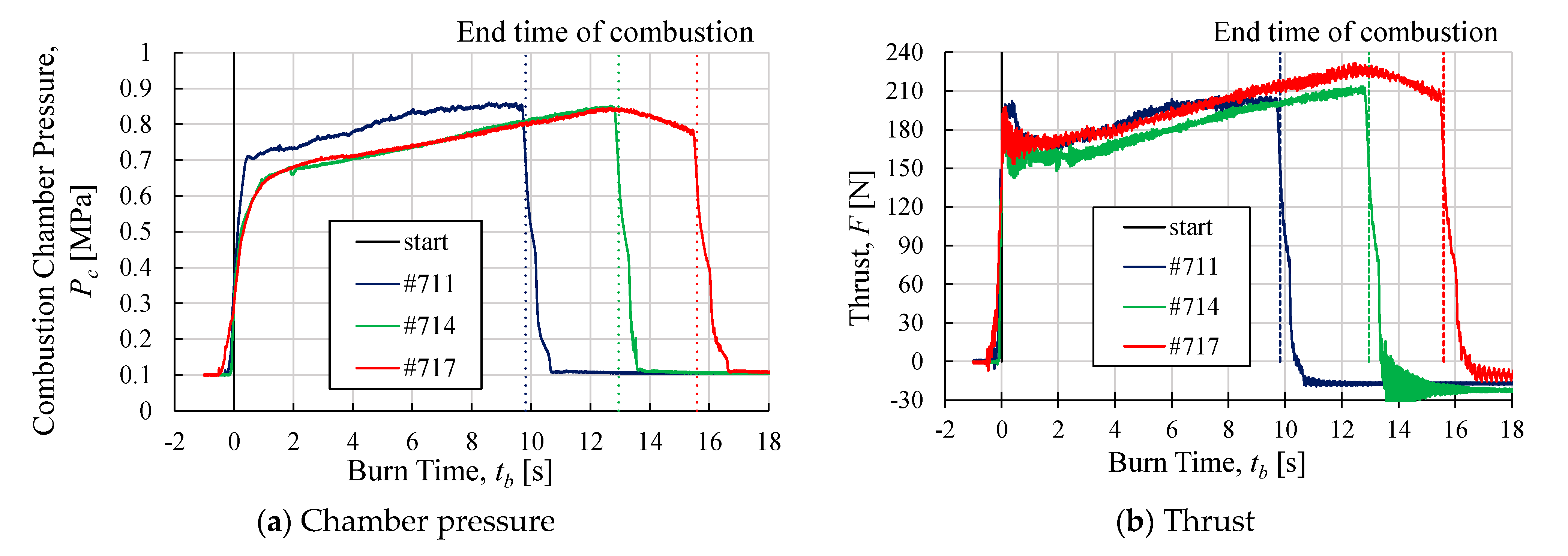
The time histories of the combustion chamber pressure and thrust are presented in Figure 22a,b, respectively, and the time-averaged values are listed in Table 6. The combustion-chamber pressures of #714 and #717 demonstrated almost the same profile, showing an increasing trend as the burn time increased. The time variation of the thrust with the burn time was also in good agreement with the time variation of the pressure. If the fuel regression rate depended only on the oxygen mass flow rate, as discussed in Section 3.1, it can be explained that the fuel mass flow rate increased with the surface area of the grain port during combustion; thus, the combustion chamber pressure also increased. In contrast to the results for #701 shown in Figure 7, the pressure gradient remained constant as the burn time increased, and this trend did not change. This suggests that the fuel regression rate characteristics did not change as the burn time increased.
The same nozzle, C1Mr, was used for all the tests. The designed combustion-chamber pressure at which the nozzle expanded optimally was 1 MPa. The increase in thrust was attributed to an increase in the combustion-chamber pressure and propellant mass flow rate.
Observation of the experimental data shows that the pressure for #711 was higher than those for #714 and #717, although the slope of the pressure increase was similar to those for #714 and #717. Although the oxygen mass flow rate for #711 was less than those for #714 and #717, as listed in Table 6, the fuel regression rate was higher; thus, the fuel mass flow rate was higher. The adiabatic flame temperature for #711 was lower than those for #714 and #717, which is unlikely to be the cause of the higher fuel regression rate for #711. To investigate the cause of this, we examined the conditions of the engine parts after the firing tests were conducted and found that the Bakelite plate used for the leading edge of the grain was significantly burned in #711, as shown in Figure 23. In contrast, #714 and #717 comprised graphite as the leading-edge plate, and no erosion or other burn damage occurred. This suggests that the fuel regression rate for #711 was affected by the burning of the Bakelite plate. However, Bakelite does not burn easily, and even if the mass loss of the burned Bakelite was considered, the fuel regression rate was inconsistent with the experimental values. Therefore, it is highly likely that the fuel mass flow rate increased owing to the change in the flow field at the leading edge of the fuel grain caused by the combustion of the Bakelite plate.
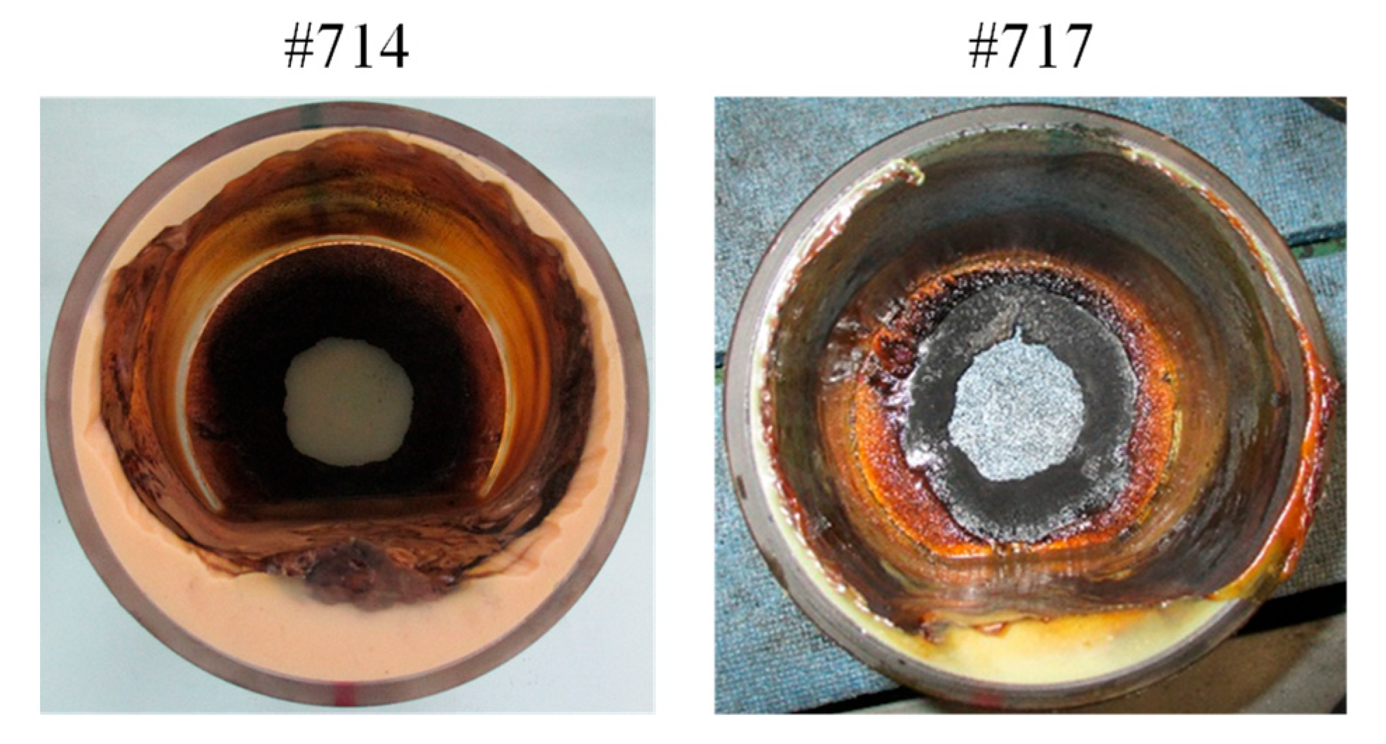
On comparing the combustion-chamber pressure and thrust histories for #714 and #717, both the pressure and thrust for #717 were observed to change from an increasing trend to a decreasing trend after approximately 13 s. This burn time was the time when the LT fuel was expected to burn out in the preliminary estimation; even after the LT fuel burned out, there was a PMMA case with LT fuel grains molded into it in the combustion chamber, and this case continued to burn in #717. However, the fuel regression rate of PMMA was lower than that of the LT fuel, thus resulting in a lower fuel mass flow rate and, consequently, a lower combustion chamber pressure and thrust. Figure 24 presents photographs of the LT fuel after the firing tests, as observed from the swirler injector side. In #714, the LT fuel remained in the PMMA case, although the bottom of the case was thicker because the molten LT fuel flowed and was collected after the firing test. This indicates that the LT fuel maintained its cylindrical shape during combustion even though the burn time was increased. When combustion was suppressed with the supply of nitrogen gas, the molten fuel flowed to the bottom and accumulated. In #717, the LT fuel was almost completely consumed, except at the bottom of the PMMA case. It can also be confirmed that the PMMA case burned. However, residual LT fuel was also observed at the bottom of the PMMA case. This suggests that the LT fuel that was liquefied during combustion remained in the combustion chamber for a long time owing to the swirling flow.
Figure 25 presents the fuel regression rates for #714 and #717 according to the leading-edge parameter. The data for #711 were excluded from the graph based on the above discussion. Compared to the correlation equation for the fuel regression rate for LT421 obtained in Section 3.1, the values for #714 and #717 with varying burn times were lower. Even when compared to the data deviation for the PP fuel, this difference in values is considered significant, thus indicating that this leading-edge parameter alone is insufficient for sorting the data. It is suspected that one factor causing this difference is the change in the thickness of the boundary layer formed by the swirling flow in the leading-edge region as the port diameter increased. In the tests conducted, the port diameter of the LT fuel varied from 40 to 100 mm. In contrast, the firing tests were conducted by the authors [49] when the fuel port diameter was increased to 110 mm. Thus, in this study, the correlation equation covers the range of port diameters. Hence, the change in the swirling flow field due to the increase in the fuel port diameter is not considered to be the cause of the deviation from the correlation equation. This factor is yet to be elucidated and is a subject to investigate in future research.

3.2.2. Effect of Burn Time on Wall Temperatures

The wall temperatures of the nozzle throat and post-combustion chamber are presented in Figure 26. The same post-combustion chamber and nozzle were used for tests 711, 714, and 717. The time histories of the nozzles showed that the temperature changes were small from the start of combustion until 2 s. Subsequently, the temperature increased from 2 to 4 s. From 4 s, the temperature increase slowed and continued at an almost constant rate, reaching its peak value 2–3 s after the end of combustion. The change in the temperature gradient from 2 s to 4 s and after 4 s appeared to correspond to the effect of the transient phase from the start of combustion to approximately 2 s, as shown in Figure 7 and Figure 15. During this period, the combustion state changed significantly, and the flow of the burned gas through the nozzle was unsteady. After 4 s, the combustion state was stabilized, the burned gas flow through the nozzle was nearly steady, the boundary layer near the nozzle wall developed, and the heat transfer decreased. A difference in the temperature gradient was observed in the temperature history after 4 s, with the gradient increasing in the order of the total nozzle usage time. The inspection of the nozzle after each firing test showed no change in the nozzle-throat diameter until #719; however, the surface became rough at the nozzle inlet contraction.
The wall temperature of the post-combustion chamber exhibited greater temporal variation than the time history of the nozzle wall. Post-experimental inspections showed that, although the wall temperature was higher in the post-combustion chamber than in the nozzle, no degradation of the surface properties or erosion occurred. It was hypothesized that this is because the flow path in the post-combustion chamber has an enlarged shape, as shown in Figure 3, resulting in a slower burned gas velocity near the wall surface and a lower heat flux owing to heat convection. However, because the surface area was greater than that of the nozzle, the amount of heat transferred from the burned gas was greater than that from the nozzle, and the temperature gradient was higher than that of the nozzle. The difference in temperature change among the firing tests is thought to be related to the condition of the Bakelite used as the heat-insulation material outside the post-combustion chamber, as shown in Figure 27. Before the firing test in #711, the Bakelite was partly carbonized to a gray color because of the heat from the post-combustion chamber. The backside of the Bakelite was not burned, corresponding to the position of the LT fuel, and no change in the color of the Bakelite occurred. In the firing test in #714, the carbonization of Bakelite progressed further, and fine crack-like surface features were observed. In the firing test in #717, the thickness of the Bakelite did not change, but carbonization progressed further in the direction of the thickness. The temperature history of #711 exhibited a gradual temperature gradient from 2 s to 6 s, and the gradient increased after 6 s. According to one study [53], the thermal degradation of phenolic resins proceeds slowly up to approximately 700 K, and the rate of degradation increases beyond this temperature. Based on this characteristic, Bakelite was considered to have acted as an ablator and absorbed heat from the post-combustion chamber until approximately 6 s after the start of combustion in #711. However, because of the thermal degradation of the Bakelite surface in this test, the ablation effect of Bakelite was weakened in #714 and #717, and a large temperature gradient and continuous increase in temperature were observed after 2 s.

4. Conclusions

The fuel regression rate of LT421, a low-melting-point thermoplastic fuel combined with a swirling-flow-type engine, was investigated to obtain a high fuel regression rate. Gaseous oxygen was used as the oxidizer, and Sg = 19.4 was set as the swirl strength. The oxygen mass flow rate and burn time were varied as the parameters of the oxidizer mass flux. In addition, the heat resistance of the engine components, which is necessary for the practical use of the engine, was investigated via firing tests with different burn times. In particular, the presence of erosion in the post-combustion chamber and the nozzle fabricated using graphite are discussed. The findings of this study are as follows.
When the LT fuel was applied to the SOFT engine, an ignition delay of the fuel grain occurred. This did not occur in the case of the PP fuel in a similar engine. A transient combustion state, wherein the combustion chamber pressure and thrust fluctuated, was observed for up to approximately 2 s after ignition. After this state, the combustion stabilized, and the combustion pressure tended to increase or remain constant over time. This trend with respect to the burn time did not change until 13 s, when the fuel burned out, thus suggesting that the fuel regression rate was strongly dependent on the oxygen mass flow rate rather than the oxidizer mass flux.
The LT fuel was molded into a cylindrical PMMA case for the firing tests. When the oxygen mass flow rate was 100 g/s or greater, the shear force generated by the swirling oxygen flow caused the fuel grains to separate from the PMMA case. Fuel separation occurred immediately after the start of combustion, and the separated fuel passed through the nozzle throat and was exhausted outside the engine because of its high flexibility.
By attaching fins to the inner surface of the cylindrical PMMA case, the LT fuel was burned without separation, and the highest fuel regression rate of 4.88 mm/s was achieved at an oxygen mass flow rate of 190 g/s, which corresponded to Gox = 72.4 kg/(m2s). Although the fins mainly comprised acrylic resin and the fuel regression rate was lower than that of the LT fuel, the change in the flow field due to the fins was small. The pressure and thrust profiles did not differ from those of the case without fins.
At the same oxidizer mass flux, the fuel regression rate of LT421 was approximately four times greater than that of PP when using the same engine. The fuel regression rate of LT421 was even higher than that of LT460, owing to its lower viscosity coefficient. The correlation between the fuel regression rate and oxidizer mass flux obtained with the oxygen mass flow rate as a parameter was r ˙ = 0.0834 G o x 0.9335 , which had a higher mass flux exponent than those of PP and LT460. When the fuel regression rate was organized in terms of the grain leading-edge parameter, the data could be organized with the same exponent as the correlation obtained for the same engine using PP fuel. Based on the time history of the combustion-chamber pressure, it was more appropriate to organize the fuel regression rate for this engine as a parameter based on the oxygen mass flow rate. However, the results of the firing tests with the burn time as a parameter could not be organized well using only this parameter.
The fuel grain, which was 30 mm thick, burned out after a burn time of 16 s. In contrast, the molten fuel remained at the bottom of the combustion chamber after combustion. LT421 was considered to be the fuel that was liquefied during combustion, it remained in the combustion chamber for a long time owing to the swirling flow.
The roughness of the nozzle inlet surface became more noticeable as the number of uses increased and the wall temperature gradient during combustion increased. The erosion of the nozzle throat occurred when the oxygen mass flow rate increased from 140 to 190 g/s. The increase in the wall temperature of the post-combustion chamber was significantly affected by the condition of the Bakelite installed outside the chamber. The post-combustion chamber reached a higher wall temperature than the nozzle owing to its larger surface area; however, no erosion was observed.

Author Contributions

Conceptualization, T.O., M.T. and T.S.; methodology, T.O., M.T. and T.S.; software, T.O. and M.T.; validation, T.O., M.T. and T.S.; formal analysis, T.O. and M.T.; investigation, T.O. and M.T.; resources, T.O. and M.T.; data curation, T.O. and M.T.; writing—original draft preparation, T.S.; writing—review and editing, T.O., M.T. and T.S.; supervision, T.S. All authors have read and agreed to the published version of the manuscript.

Funding

This research received no external funding.

Data Availability Statement

Not applicable.

Acknowledgments

The authors would like to thank Hitomi Ozaki and Naoki Yabe for their technical support during the firing tests.

Conflicts of Interest

The authors declare no conflict of interest.

Nomenclature

A i n j area of circle with swirler exit diameter
A s l i t cross-sectional area of swirler slit
A t nozzle throat area
C*characteristic exhaust velocity
C d flow coefficient
dgrain port diameter
d a v e time-averaged grain port diameter
d i initial grain port diameter
d f final grain port diameter
d t nozzle throat diameter
Erelative error
G o x oxidizer mass flux
Ispspecific impulse
J φ axial flux of angular momentum
J x axial flux of the axial thrust
Llength of fuel grain
L f axial distance of flow-development region
m ˙ f fuel mass flow rate
m ˙ o x oxidizer mass flow rate
m ˙ p propellant mass flow rate
M w molar mass of burned gas
n number of swirler slit
p static pressure of fluid
P c combustion chamber pressure
P u orifice upstream pressure
Rfinal to initial grain port diameter ratio
R 0 universal gas constant
R o x gas constant of oxygen
r radius
r e x radius of swirler slit exit
r ˙ time-averaged fuel regression rate
r ˙ f fuel regression rate in grain leading-edge region
r ˙ r fuel regression rate in grain rear edge-region
S swirl number
S g geometrical swirl number
S p total surface area of grain port and post-combustion chamber
t b burn time
T c burned gas temperature at combustion chamber
T u orifice upstream temperature
u absolute flow velocity
u x axial flow velocity
u θ tangential flow velocity
w width of swirler slit
w f burned mass of fuel grain
x axial distance along fuel grain port
y thickness of molten fuel layer
η C C* efficiency
κ specific heat ratio
ρ density of fluid
ρ b density of burned gas
ρ f density of fuel grain
φ equivalence ratio
μ viscosity coefficient
μ o x viscosity coefficient of oxygen
τ w shear stress
Subscripts
expexperimental
ththeoretical

References

  1. Kuo, K.K.; Chiaverini, M.J. Challenges of Hybrid Rocket Propulsion in the 21st Century. In Fundamentals of Hybrid Rocket Combustion and Propulsion; Chaiverini, M.J., Kuo, K.K., Eds.; Progress in Astronautics and Aeronautics; AIAA: Reston, VA, USA, 2007; pp. 593–638, NASA RP-1311. [Google Scholar]
  2. Takahashi, A.; Shimada, T. Essentially Non-explosive propulsion Paving a Way for Fail-Safe Space Transportation. Transact. Jpn. Soc. Aeronaut. Space Sci. Space Technol. Jpn. 2018, 16, 1–8. [Google Scholar] [CrossRef] [Green Version]
  3. Virgin Galactic. Available online: https://www.virgingalactic.com/ (accessed on 2 May 2023).
  4. Yuasa, S.; Yamamoto, K.; Hachiya, H.; Kitagawa, K.; Oowada, Y. Development of a Small Sounding Hybrid Rocket with a Swirling-Oxidizer-Type Engine. In Proceedings of the 37th AIAA Joint Propulsion Conference and Exhibit, Salt Lake City, UT, USA, 8–11 July 2001. AIAA Paper 2001-3537. [Google Scholar] [CrossRef]
  5. Karabeyoglu, A.; Zilliac, G.; Castellucci, P.; Urbanczyk, P.; Inalhan, G.; Cantwell, B. Flight Demonstration of the High Burning Rate Hydrocarbon-Based Hybrid Rocket Fuels. In Proceedings of the 39th AIAA/ASME/SAE/ASEE Joint Propulsion Conference and Exhibit, Huntsville, AL, USA, 20–23 July 2003. AIAA Paper 2003-5196. [Google Scholar] [CrossRef]
  6. Kobald, M.; Schmierer, C.; Fischer, U.; Tomilin, K.; Petrarolo, A. A Record Flight of the Hybrid Sounding Rocket HEROS 3. Transact. Jpn. Soc. Aeronaut. Space Sci. Space Technol. Jpn. 2018, 16, 312–317. [Google Scholar] [CrossRef] [Green Version]
  7. Gilmour Space Technologies. Available online: https://www.gspace.com/ (accessed on 2 May 2023).
  8. TiSPACE. Available online: https://www.tispace.com/ (accessed on 2 May 2023).
  9. HyImpulse Technologies. Available online: https://www.hyimpulse.de/en/ (accessed on 2 May 2023).
  10. MJOLNIR SPACEWORKS. Available online: https://www.mjolnir-sw.com/ (accessed on 2 May 2023).
  11. Letara. Available online: https://www.letara.space/ (accessed on 2 May 2023).
  12. Kamps, L.; Hirai, S.; Nagata, H. Hybrid Rockets as Post-Boost Stages and Kick Motors. Aerospace 2021, 8, 253. [Google Scholar] [CrossRef]
  13. Mazzetti, A.; Merotto, L.; Pinarello, G. Paraffin-based Hybrid Rocket Engines Applications: A Review and a Market Perspective. Acta Astronaut. 2016, 126, 286–297. [Google Scholar] [CrossRef]
  14. Knuth, W.H.; Chiaverini, M.J.; Sauer, J.A.; Gramer, D.J. Solid-Fuel Regression Rate Behavior of Vortex Hybrid Rocket Engines. J. Propuls. Power 2002, 18, 600–609. [Google Scholar] [CrossRef]
  15. Yuasa, S.; Shimada, O.; Imamura, T.; Tamura, T.; Yamamoto, K. A Technique for Improving the Performance of Hybrid Rocket Engines. In Proceedings of the 35th AIAA Joint Propulsion Conference and Exhibit, Los Angeles, CA, USA, 20–24 June 1999. AIAA Paper 1999-2322. [Google Scholar] [CrossRef]
  16. Nagata, H.; Okada, K.; San’da, T.; Akiba, R.; Satori, S.; Kudo, I. New Fuel Configurations for Advanced Hybrid Rockets. In Proceedings of the 49th International Astronautical Congress, Melbourne, VIC, Australia, 28 September–2 October 1998. Paper IAF-98-S.3.09. [Google Scholar]
  17. Carrick, P.; Larson, C. Lab Scale Test and Evaluation of Cryogenic Solid Hybrid Rocket Fuels. In Proceedings of the 31st AIAA Joint Propulsion Conference and Exhibit, San Diego, CA, USA, 10–12 July 1995. AIAA Paper 1995-2948. [Google Scholar] [CrossRef]
  18. Karabeyoglu, M.A.; Altman, D.; Cantwell, B.J. Combustion of Liquefying Hybrid Propellants, Part 1: General Theory. J. Propuls. Power 2002, 18, 610–620. [Google Scholar] [CrossRef]
  19. Karabeyoglu, M.A.; Cantwell, B.J. Combustion of Liquefying Hybrid Propellants, Part 2: Stability of Liquid Films. J. Propuls. Power 2002, 18, 621–630. [Google Scholar] [CrossRef]
  20. Galfetti, L.; Merotto, L.; Boiocchi, M.; Maggi, F.; DeLuca, L.T. Experimental Investigation of paraffin-based Fuels for Hybrid Rocket Propulsion. Proc. Prog. Propuls. Phys. 2013, 4, 59–74. [Google Scholar] [CrossRef] [Green Version]
  21. Kobald, M.; Schmierer, C.; Ciezki, K.H.; Schlechtriem, S.; Toson, E.; De Luca, L.T. Viscosity and Regression Rate of Liquefying Hybrid Rocket Fuels. J. Propuls. Power 2017, 33, 1245–1251. [Google Scholar] [CrossRef]
  22. Kim, S.; Moon, H.; Kim, J.; Cho, J. Evaluation of Paraffin–Polyethylene Blends as Novel Solid Fuel for Hybrid Rockets. J. Propuls. Power 2015, 31, 1750–1760. [Google Scholar] [CrossRef]
  23. Kumar, R.; Ramakrishna, P.A. Studies on EVA-Based Wax Fuel for Launch Vehicle Applications. Propellants Explos. Pyrotech. 2016, 41, 295–303. [Google Scholar] [CrossRef]
  24. Tang, Y.; Chen, S.; Zhang, W.; Shen, R.; DeLuca, L.T.; Ye, Y. Mechanical Modifications of Paraffin-based Fuels and the Effects on Combustion Performance. Propellants Explos. Pyrotech. 2017, 42, 1268–1277. [Google Scholar] [CrossRef]
  25. Ishigaki, T.; Nakagawa, I. Improving Physical Properties of Wax-Based Fuels and Its Effect on Regression Rate. J. Propuls. Power 2020, 36, 123–128. [Google Scholar] [CrossRef]
  26. Veale, K.; Adali, S.; Pitot, J.; Brooks, M. A review of the performance and structural considerations of paraffin wax hybrid rocket fuels with additives. Acta Astronaut. 2017, 141, 196–208. [Google Scholar] [CrossRef]
  27. Oztan, C.; Coverstone, V. Utilization of additive manufacturing in hybrid rocket technology: A review. Acta Astronaut. 2021, 180, 130–140. [Google Scholar] [CrossRef]
  28. Bisin, R.; Paravan, C.; Alberti, S.; Galfetti, L. A new strategy for the reinforcement of paraffin-based fuels based on cellular structures: The armored grain—Mechanical characterization. Acta. Astronaut. 2020, 176, 494–509. [Google Scholar] [CrossRef]
  29. Bisin, R.; Paravan, C. A new strategy for the reinforcement of paraffin-based fuels based on cellular structures: The armored grain—Ballistic characterization. Acta. Astronaut. 2023, 206, 284–298. [Google Scholar] [CrossRef]
  30. Lin, X.; Qu, D.; Chen, X.; Wang, Z.; Luo, J.; Meng, D. Three-dimensional printed metal-nested composite fuel grains with superior mechanical and combustion properties. Virtual Phys. Prototyp. 2022, 17, 437–450. [Google Scholar] [CrossRef]
  31. Sakurai, T.; Oishige, Y.; Saito, K. Fuel Regression Behavior of Swirling-Injection End-Burning Hybrid Rocket Engine. J. Fluid Sci. Technol. 2019, 14, JFST0025. [Google Scholar] [CrossRef] [Green Version]
  32. Wada, Y.; Jikei, M.; Kato, R.; Kato, N.; Hori, K. Application of Low Melting Point Thermoplastics to Hybrid Rocket Fuel. Transact. Jpn. Soc. Aeronaut. Space Sci. Space Technol. Jpn. 2012, ists28, Pa_1–Pa_5. [Google Scholar] [CrossRef] [Green Version]
  33. Wada, Y.; Kawabata, Y.; Kato, R.; Kato, N.; Hori, K. Observation of Combustion Behavior of Low Melting Temperature Fuel for a Hybrid Rocket Using Double Slab Motor. Int. J. Energetic Mater. Chem. Propuls. 2016, 15, 351–369. [Google Scholar] [CrossRef]
  34. Kawabata, Y.; Banno, A.; Wada, Y.; Ozawa, K.; Shimada, T.; Kato, N.; Hori, K.; Nagase, R. Experimental Investigation of Fuel Regression Rate of Low-Melting-Point Thermoplastic Fuels in the Altering-Intensity Swirling-Oxidizer-Flow-Type Hybrid Rocket Engine. Transact. Jpn. Soc. Aeronaut. Space Sci. Space Technol. Jpn. 2018, 16, 267–273. [Google Scholar] [CrossRef]
  35. Gordon, S.; McBride, B. Computer Program for Calculation of Complex Chemical Equilibrium Compositions and Applications; National Aeronautics and Space Administration: Cleveland, OH, USA, 1994. [Google Scholar]
  36. Wada, Y.; Kato, R.; Kato, N.; Hori, K. Small Rocket Launch Experiment using Low Melting Point Thermoplastic Fuel/N2O Hybrid Rocket. In Proceedings of the 49th AIAA/ASME/SAE/ASEE Joint Propulsion Conference, San Jose, CA, USA, 14–17 July 2013. AIAA Paper 2013-4050. [Google Scholar] [CrossRef]
  37. Banno, A.; Wada, Y.; Mishima, Y.; Tsugoshi, T.; Kato, N.; Hori, K.; Nagase, R. Pyrolysis Behavior of a Paraffin-based Thermoplastic Polymer used in Hybrid Rocket Fuel. Int. J. Energetic Mater. Chem. Propuls. 2019, 18, 341–354. [Google Scholar] [CrossRef]
  38. Oishi, T.; Tokyo Metropolitan University, Hino, Tokyo, Japan; Kato, N.; Katazen Corp., Obu, Aichi, Japan. Personal communication, 2021.
  39. Beer, J.M.; Chigier, N.A. Combustion Aerodynamics; Reprint; Robert E. Krieger Publishing Company: Malabar, FL, USA, 1983; pp. 109–115. [Google Scholar]
  40. Saito, D.; Yuasa, S.; Hirata, K.; Sakurai, T.; Shiraishi, N. Combustion Characteristics of Paraffin-Fueled Swirling Oxidizer-Flow-Type Hybrid Rocket Engines. In Proceedings of the 48th AIAA/ASME/SAE/ASEE Joint Propulsion Conference and Exhibit, Atlanta, GA, USA, 30 July–1 August 2012. AIAA Paper 2012-3904. [Google Scholar] [CrossRef]
  41. Yuasa, S.; Ide, T.; Masugi, M.; Sakurai, T.; Shiraishi, N.; Shimada, T. Visualization and Emission Spectra of Flames in Combustion Chamber of Swirling-Oxidizer-Flow-Type Hybrid Rocket Engines. J. Therm. Sci. Technol. 2011, 6, 268–277. [Google Scholar] [CrossRef] [Green Version]
  42. Zhang, Z.; Lin, X.; Wang, Z.; Wu, K.; Luo, J.; Fang, S.; Zhang, C.; Li, F.; Yu, X. Effects of swirl injection on the combustion of a novel composite hybrid rocket fuel grain. Acta Astronaut. 2022, 199, 174–182. [Google Scholar] [CrossRef]
  43. Karabeyoglu, M.A.; Cantwell, B.J.; Zilliac, G. Development of Scalable Space-Time Averaged Regression Rate Expressions for Hybrid Rockets. J. Propuls. Power 2007, 23, 737–747. [Google Scholar] [CrossRef]
  44. Yuasa, S.; Shiraishi, N.; Sakamoto, M.; Sezaki, C.; Hirata, K.; Sakurai, T. Evaluation Method of C* Efficiency of Swirling-Oxidizer-Flow-Type Hybrid Rocket Engines. J. Jpn. Soc. Aeronaut. 2011, 59, 97–101. (In Japanese) [Google Scholar] [CrossRef] [Green Version]
  45. Merotto, L.; Boiocchi, M.; Milova, P.; Monzani, M.R.; Galfetti, L. Development of an Experimental Lab-scale Set Up for Transient Combustion Investigation in Hybrid Rockets. In Proceedings of the 63rd International Astronautical Congress, Naples, Italy, 1–5 October 2012. Paper IAC-12-C4.2.25. [Google Scholar]
  46. Bellomo, N.; Barato, F.; Faenza, M.; Lazzarin, M.; Bettella, A.; Pavarin, D. Numerical and Experimental Investigation of Unidirectional Vortex Injection in Hybrid Rocket Engines. J. Propuls. Power 2013, 29, 1097–1113. [Google Scholar] [CrossRef]
  47. Kitagawa, K.; Sakurazawa, T.; Yuasa, S. Combustion Experiment to Evaluate a LOX Vaporization Nozzle for a Swirling-Oxidizer-Flow-Type Hybrid Rocket Engine with a 1500N-Thrust. Space Technol. Jpn. JSASS 2007, 6, 47–54. (In Japanese) [Google Scholar] [CrossRef] [Green Version]
  48. Yuasa, S.; Shiraishi, N.; Hirata, K. Controlling Parameters for Fuel Regression Rate of Swirling-oxidizer-flow-type Hybrid Rocket Engine. In Proceedings of the 48th AIAA/ASME/SAE/ASEE Joint Propulsion Conference and Exhibit, Atlanta, GA, USA, 30 July–1 August 2012. AIAA Paper 2012-4106. [Google Scholar] [CrossRef]
  49. Sakurai, T.; Yuasa, S.; Ando, H.; Kitagawa, K.; Shimada, T. Performance and Regression Rate Characteristics of 5-kN Swirling-Oxidizer-Flow-Type Hybrid Rocket Engine. J. Propuls. Power 2017, 33, 891–901. [Google Scholar] [CrossRef]
  50. Matsui, K.; Tsuji, H.; Makino, A. The Effects of Water Vapor Concentration on the Rate of Combustion of an Artificial Graphite in Humid Air Flow. Combust. Flame. 1983, 50, 107–118. [Google Scholar] [CrossRef]
  51. Acharya, R.; Kuo, K.K. Effect of Chamber Pressure and Propellant Composition on Erosion Rate of Graphite Rocket Nozzle. J. Propuls. Power 2007, 23, 1242–1254. [Google Scholar] [CrossRef]
  52. Kamps, L.; Hirai, S.; Sakurai, K.; Viscor, T.; Saito, Y.; Guan, R.; Isochi, H.; Adachi, N.; Itoh, M.; Nagata, H. Investigation of Graphite Nozzle Erosion in Hybrid Rockets Using Oxygen/High-Density Polyethylene. J. Propuls. Power 2020, 36, 423–434. [Google Scholar] [CrossRef]
  53. Solyman, W.S.E.; Nagiub, H.M.; Alian, N.A.; Shaker, N.O.; Kandil, U.F. Synthesis and characterization of phenol/formaldehyde nanocomposites: Studying the effect of incorporating reactive rubber nanoparticles or Cloisite-30B nanoclay on the mechanical properties, morphology and thermal stability. J. Radiat. Res. Appl. Sci. 2016, 10, 72–79. [Google Scholar] [CrossRef] [Green Version]
Figure 1. Theoretical specific impulse of LT421-oxygen and typical HR fuels calculated using NASA CEA.
Aerospace 10 00713 g001
Figure 2. Viscosity coefficient of LT421 and LT460.
Aerospace 10 00713 g002
Figure 3. Schematic of the engine and the swirler injector.
Aerospace 10 00713 g003
Figure 4. Molded LT fuel into (a) PMMA and (b) finned cases. (c) schematic of the finned case.
Aerospace 10 00713 g004
Figure 5. Experimental apparatus.
Aerospace 10 00713 g005
Figure 6. Specific impulse of LT421-oxygen for the equivalence ratio.
Aerospace 10 00713 g006
Figure 7. Time history of the oxygen mass flow rate, combustion chamber pressure, and thrust for #701.
Aerospace 10 00713 g007
Figure 8. Appearance of the exhaust plume during firing for #701.
Aerospace 10 00713 g008
Figure 9. Typical time history for the same SOFT engine with PP fuel using a similar swirler injector and ignitor.
Aerospace 10 00713 g009
Figure 10. Small oscillations observed in the thrust.
Aerospace 10 00713 g010
Figure 11. Data for the grain-separation event for #704.
Aerospace 10 00713 g011
Figure 12. Appearance of the exhaust plume at the nozzle outlet for the grain-separation event for #704.
Aerospace 10 00713 g012
Figure 13. Adhesive strength test between the PMMA case and the LT421 fuel.
Aerospace 10 00713 g013
Figure 14. Schematic of the shear stress of the swirling flow acting on the inner surface of the LT fuel grain.
Aerospace 10 00713 g014
Figure 15. Time history of the oxygen mass flow rate, combustion chamber pressure, and thrust for #715.
Aerospace 10 00713 g015
Figure 16. Photograph of the fuel grain after firing test for #715.
Aerospace 10 00713 g016
Figure 17. Time history of the oxygen mass flow rate, combustion chamber pressure, and thrust for #719.
Aerospace 10 00713 g017
Figure 18. Photographs of the nozzle before and after the firing test for #719.
Aerospace 10 00713 g018
Figure 19. Relationship between fuel regression rate and oxidizer mass flux: LT460 data (Kawabata, Y.; Banno, A.; Wada, Y.; Ozawa, K.; Shimada, T.; Kato, N.; Hori, K.; Nagase, R. Experimental Investigation of Fuel Regression Rate of Low-Melting-Point Thermoplastic Fuels in the Altering-Intensity Swirling-Oxidizer-Flow-Type Hybrid Rocket Engine. Transact. Jpn. Soc. Aeronaut. Space Sci. Space Technol. Jpn. 2018, 16, 267–273. [34]), PP data (Yuasa, S.; Shiraishi, N.; Hirata, K. Controlling Parameters for Fuel Regression Rate of Swirling-oxidizer-flow-type Hybrid Rocket Engine. In Proceedings of the 48th AIAA/ASME/SAE/ASEE Joint Propulsion Conference and Exhibit, Atlanta, GA, USA, 30 July–1 August 2012. AIAA Paper 2012-4106. [48]).
Aerospace 10 00713 g019
Figure 20. Burned surface of the grain after the test conducted for #701.
Aerospace 10 00713 g020
Figure 21. Relationship between the regression rate and leading-edge parameter: PP data (Sakurai, T.; Yuasa, S.; Ando, H.; Kitagawa, K.; Shimada, T. Performance and Regression Rate Characteristics of 5-kN Swirling-Oxidizer-Flow-Type Hybrid Rocket Engine. J. Propuls. Power 2017, 33, 891–901. [49]).
Aerospace 10 00713 g021
Figure 22. Time histories of the combustion chamber pressure and thrust.
Aerospace 10 00713 g022
Figure 23. Bakelite and graphite plates used for the leading edge of the grain for #711 and #714.
Aerospace 10 00713 g023
Figure 24. Photographs of the LT fuel after the firing tests observed from the swirler injector side.
Aerospace 10 00713 g024
Figure 25. Fuel regression rates for #714 and #717 according to the leading-edge parameter: PP data (Sakurai, T.; Yuasa, S.; Ando, H.; Kitagawa, K.; Shimada, T. Performance and Regression Rate Characteristics of 5-kN Swirling-Oxidizer-Flow-Type Hybrid Rocket Engine. J. Propuls. Power 2017, 33, 891–901. [49]).
Aerospace 10 00713 g025
Figure 26. Wall temperatures of the nozzle throat and post-combustion chamber.
Aerospace 10 00713 g026
Figure 27. Condition of the Bakelite used as the heat-insulation material outside the post-combustion chamber.
Aerospace 10 00713 g027
Table 1. Compositions and properties of LT fuels.
Sample No.LT421LT462LT464LT460
CompositionStyrene series resin [%]891113
Low melting resin [%]13333231
Liquefacient (fatty acid) [%]4036
Paraffin oil [%]75575349
Element ratioC [%]35363636
H [%]65636363
O [%]0.40.611
Physical propertySpecific gravity0.890.920.920.92
Mechanical propertyYang’s modulus [kPa]37.7169.3267.7617.7
Maximum stress [MPa]0.090.260.410.58
Maximum strain [%]378.8319.4344.0300.2
Table 2. Maximum specific impulse and O/F values at Pc = 4 MPa.
FuelLT421Paraffin Wax
(FT0070)
PEPPHTPB
Isp [s]257.3289.6290.2286.7287.0
O/F, mass3.022.462.442.442.08
Table 3. Experimental conditions and target values for each firing test.
3.1. Firing Tests Varying Oxygen Mass Flow Rate
Exp. No. m ˙ o x t b LNozzle d t φ Grain CaseRefractory Plate
(g/s)(s)(mm)(-)(mm)(-)(-)Leading-Edge Side
#68850450C1M121.28PMMAGraphite
#690854111C1M121.28PMMABakelite
#6981154111C4M181.17PMMABakelite
#7011154111C4M181.17PMMABakelite
#7041504111C4M181.34PMMAGraphite
#7071154111C1M121.46PMMABakelite
#7151504111C1Mr-3 *181.34FinnedGraphite
#7192004111C1Mr-5 *181.29FinnedGraphite
3.2. Firing Tests Varying Burn Time
#711801091.4C1Mr-1 *18-PMMABakelite
#714801391.4C1Mr-2 *18-PMMAGraphite
#717801691.4C1Mr-4 *18-PMMAGraphite
* The numbers indicate the number of times the nozzle was used.
Table 4. Time-averaged results of the firing tests varying oxygen mass flow rate.
Exp. No. m ˙ o x m ˙ f d f G o x t b φ P c F r ˙ η C *
(g/s)(g/s)(mm)(kg/(m2s))(s)(-)(MPa)(N)(mm/s)(-)
#68848.9 ± 0.611.353.4628.5 ± 2.43.780.770.775841.77 ± 0.080.97
#69077.8 ± 1.034.157.0342.1 ± 3.43.781.461.5241762.26 ± 0.100.99
#698107.9 ± 1.3Grain separation
#701107.0 ± 1.353.864.1050.3 ± 3.83.641.670.9772293.32 ± 0.131.07
#704140.8 ± 1.8Grain separation
#707111.9 ± 1.4Grain separation
#715140.3 ± 1.862.868.5862.8 ± 4.63.631.491.2742813.93 ± 0.151.04
#719190.3 ± 2.482.875.6972.4 ± 5.13.661.451.6984254.88 ± 0.181.11
Table 5. Lengths of the leading-edge regions in each firing test.
Exp. No. m ˙ o x μ o x L f L
(g/s)(Pa·s)(mm)(mm)
#68848.9 ± 0.62.015 × 10−576.850
#69077.8 ± 1.02.031 × 10−586.1111
#701107.0 ± 1.32.020 × 10−593.4111
#715140.3 ± 1.82.026 × 10−599.9111
#719190.3 ± 2.42.034 × 10−5107.7111
Note: d i = 40 mm and Sg = 19.4 were used for the calculation.
Table 6. Time-averaged results of the firing tests varying burn time.
Exp. No. m ˙ o x m ˙ f d f G o x t b φ P c F r ˙ η C * Tc,th
[g/s][g/s][mm][kg/(m2s)][s][-][MPa][N][mm/s][-][K]
#71175.2 ± 0.938.486.5923.9 ± 1.69.821.700.7871882.37 ± 0.081.242223
#71482.8 ± 1.033.191.1924.5 ± 1.612.951.330.7391831.98 ± 0.061.023006
#71782.5 ± 1.032.797.8822.1 ± 1.415.591.320.7501991.86 ± 0.061.043018
Disclaimer/Publisher’s Note: The statements, opinions and data contained in all publications are solely those of the individual author(s) and contributor(s) and not of MDPI and/or the editor(s). MDPI and/or the editor(s) disclaim responsibility for any injury to people or property resulting from any ideas, methods, instructions or products referred to in the content.