Abstract
With the in-depth research on hypersonic aerodynamics and hypersonic propulsion technology, humans are growing closer to space travel. Recent studies have shown that the pre-cooled air-turborocket (ATR) or turboexpander engines are some of the potential propulsion methods for reusable space vehicles and single stage-to-orbit (SSTO) missions because they have a high specific impulse at low Mach numbers, which can overcome the problem of the “thrust gap” in turbine-based combined-cycle (TBCC) engines. The ATR engine needs an additional oxidizing agent and the turboexpander engine usually uses hydrogen as fuel, which has low energy density and poor safety. To address this problem, this paper proposed a high-energy-density (HED) hydrocarbon-fueled turboexpander engine, and its feasibility has been proven through a simplified thermodynamic model. Through detailed thermodynamic analysis based on the energy and pressure balance, this paper analyzed the performance characteristics of the engine to evaluate its capacity to work in a wide speed range at low Mach numbers. The results show that the endothermic hydrocarbon-fueled turboexpander engine has good specific impulse in Mach 0∼4 at an equivalence ratio of 0.7∼1.3, and the turboexpander engine can be combined with the dual-mode scramjet and become an efficient acceleration method for SSTO missions and the reusable spacecraft.
1. Introduction
Many countries and co-operations are turning their attention and budgets to hypersonic propulsion systems, and there has been significant progress on such technologies in terms of supersonic inlet design and hypersonic aerodynamics. Research on dual-mode scramjets has widened the maximum flight Mach numbers, but ramjet engines cannot work at low Mach numbers. This leads to the combined-cycle engine becoming the mainstream of future propulsion systems due to its overall performance and wide adoption. The main combined-cycle power systems that have been studied include the rocket-based combined-cycle (RBCC) engine and the TBCC engine [1,2].
Japan and the United States studied a special TBCC engine, called the ATR engine, which can be used on a repeatable aircraft [3,4]. Contemporary designs of the ATR engine were based on the concept of an Italian researcher named Campini, who developed a kind of jet engine where compressed air is supplied by a fan driven by a piston engine [4]. In the ATR engine, an independent gas generator is used to generate fuel-rich gas for the turbine to drive the compressor to pressurize the incoming air. Then, the air enters the combustor. In the combustor, pressurized air from the compressor and fuel-rich gas from the turbine are mixed and burned, and then high-temperature gas passes through the nozzle to generate thrust. ATR engines can use a variety of fuel systems, with a specific impulse range of 600∼1500 s, a thrust-to-weight ratio of 10∼20, a flight airspace of 0∼25 km, and a flight speed range of Mach 0∼4 [5]. Nan et al. [6] carried out thermodynamic simulation and experimental research on the bipropellant ATR engine, showing that the engine can achieve a specific impulse of more than 800 s for the entire envelope, and proved that the ATR engine is a reliable propulsion system in the low Mach number range for space vehicles. In 1986, the Japanese Institute of Space and Astronautical Science (ISAS) proposed the air turboramjet with expander cycle (ATREX) engine, in which an expansion cycle was developed on the basis of the ATR engine that uses coolant expansion to drive the turbine [7,8]. It has heat exchange components installed in the intake and near the combustor to heat up the coolant. Compared to the gas-cycle air-turborocket engine (ATR-GG), its structure and thermodynamic cycle are more complex and more difficult to control. On the basis of the ATREX, ISAS further developed a pre-cooled turbine engine (PCTJ). From 2008 to 2014, the PCTJ ground test was carried out with liquid hydrogen as a coolant and fuel, and a balloon-based operation vehicle (BOV) platform was used to carry out the test [9]. The flight test was carried out to verify that the PCTJ can achieve a working time of more than 30 s under Mach 2.0 conditions [9,10,11]. In 2022, ISAS conducted Mach 4 simulation experiments on the PCTJ engine and verified the starting sequence under Mach 4 conditions and the reliability of the turbomachinery in a short time frame [12].
Other types of cycles have been proposed and analyzed based on the ATR and ATREX engines. Scimitar is a wide-speed-range engine design driven by a turboexpander, which is designed by Reaction Engines Ltd., UK. The core compressor is driven by a closed Brayton cycle with helium, and the bypass fan is driven by the pre-combustion gas of liquid hydrogen fuel [13,14]. The Scimitar engine can work in the speed range of Mach 0∼5 by adjusting the working mode of each component, and performance analysis shows that the engine has a specific impulse of more than 3400 s at low speed and can be as high as 4077 s at Mach 4 [15]. Li et al. [16] analyzed the performance of the solid propellant ATR engine. The specific thrust of the solid propellant ATR engine can reach 3000 m/s, but its specific impulse is much lower than that of the liquid propellant ATR engine, which is lower than 800 s. Miranda et al. [17] analyzed a liquid hydrogen-fueled ATR engine without pre-combustion and pre-cooling via parametric analysis of non-dimensional parameters and performance, and provided the design operating line from take-off to Mach 4. Zhao et al. [18] proposed a pre-cooled and fuel-rich pre-burned mixed-flow turbofan (PFPMT) cycle, which uses a fuel-rich gas generator as the combustor of the turbofan. The specific thrust and the specific impulse of this cycle can be greater than 1100 m/s and 3650 s, respectively. The NUAA-PTRE (Nanjing University of Aeronautics and Astronautics, pre-cooled turborocket engine) uses endothermic hydrocarbon and liquid oxygen as coolant to pre-burn the gas generator [19,20]. This engine can work at Mach 0∼6, and the specific impulse reaches its highest at Mach 2 and Mach 4.2, which is about 1030 s. Luo et al. [21] applied the pulse detonation cycle (PDC) on the ATR and ATREX engines and proposed hybrid pulse detonation engines, which can improve the hot gas pressure, making it 1.84 and 1.96 times higher than traditional ATR and ATREX engines, respectively.
Although the ATR expander engine fueled by liquid hydrogen or liquid methane [22] has great performance, the use of liquid hydrogen or methane as fuel has problems such as low energy density, large loading space, and poor safety. In addition, when the aircraft enters hypersonic flight, the pre-cooler needs to deeply cool the high-temperature air in a very short time. In this situation, ice immediately forms when the water in the air makes contact with the low-temperature pre-cooler, resulting in the loss of mainstream pressure and decreased engine performance. Compared to liquid hydrogen and liquid natural gas, HED hydrocarbon fuel has a high energy density and relatively stable physical properties and can be stored in a wide temperature range [23]. Furthermore, HED hydrocarbon fuel has an additional chemical heat sink, which can be used for the thermal protection of the wall of the combustor and nozzle [24,25,26]. The high-temperature hydrocarbon-fueled turboexpander was originally applied to regenerative active cooling in the scramjet engine. Here, hydrocarbon fuel with a high heat sink is heated through the wall of the combustor and nozzle and enters the turboexpander [27]. The turboexpander can drive fuel pumps or generate electric power through a generator. Prototype experiments have proven that high-temperature endothermic hydrocarbon fuel has the ability to effectively drive the turboexpander in the concept of an endothermic hydrocarbon-fueled turboexpander [28,29].
The HED hydrocarbon-fueled non-precooled turboexpander cycle can simplify the engine structure and increase the thrust-to-weight ratio of the full-speed-range combined-cycle engine. The cycle has high specific impulse and specific thrust under a high equivalence ratio condition, which is more suitable for the needs of low-Mach-number acceleration. Since HED hydrocarbon fuel has a poor working capacity in turboexpanders, this paper first demonstrates the feasibility of an endothermic hydrocarbon fuel expansion cycle. Based on the data on the physical properties of different types of hydrocarbon fuels in existing studies, a thermodynamic model of an HED hydrocarbon-fueled turboexpander engine is established, and the performance of the engine is modeled and simulated. Parametric studies are performed with the model, and the sensitivity of non-dimensional parameters and cycle performance are analyzed. Finally, the characteristics of a Mach 0∼4 cycle are analyzed. The results show that the HED hydrocarbon-fueled turboexpander engine is suitable for reusable space vehicles or SSTO missions and can be a solution to the low-Mach-number acceleration process of the combined engine.
2. Working Principle and Feasibility of the Turboexpander Engine
2.1. Working Principle of Turboexpander Engine
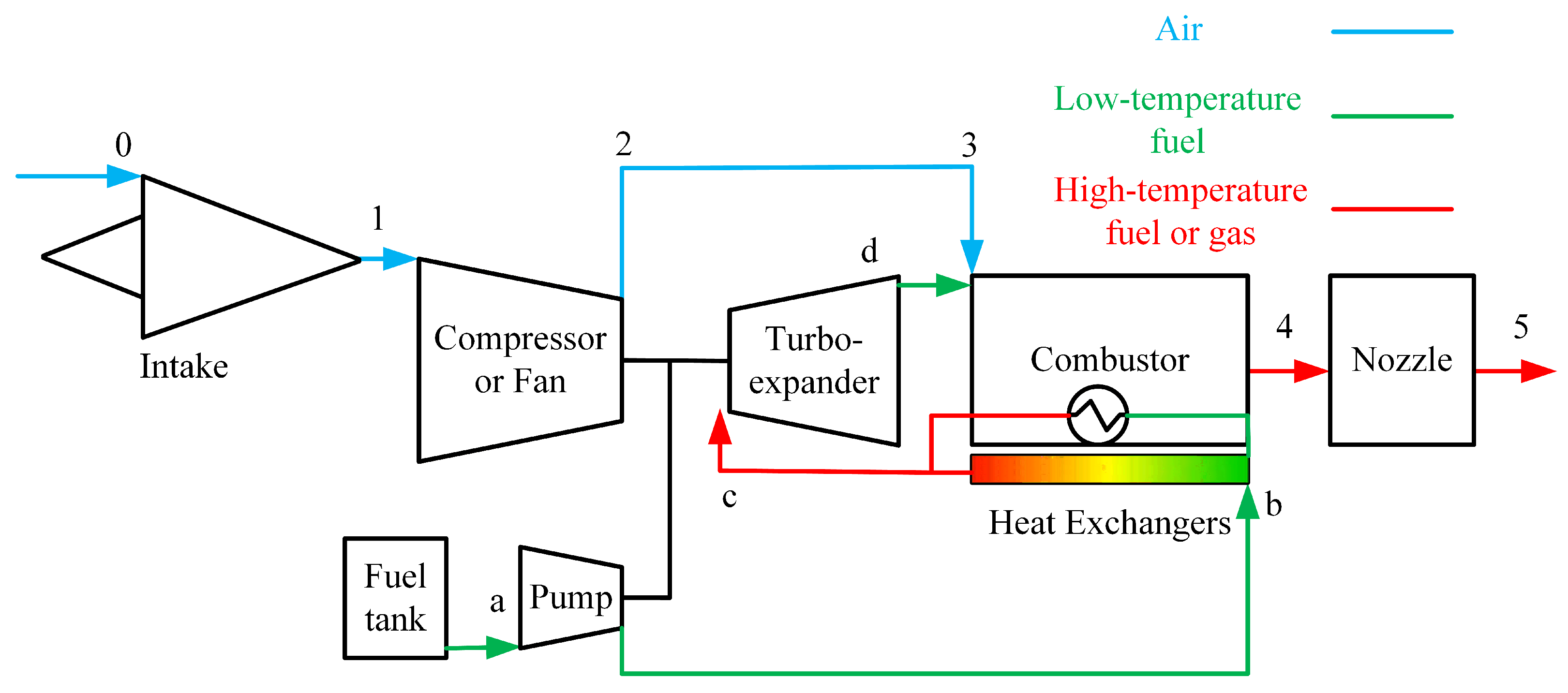
The cycle scheme of the turboexpander engine is shown in Figure 1. The scheme is composed of a Rankine cycle with fuel as the working fluid and a Brayton cycle with air as the working fluid. On the fuel side, the fuel is pressurized to a high pressure using a pump, and it then enters the heat exchanger in the combustor. The heat generated by the combustor heats the fuel to a high temperature to drive the turboexpander, and the energy generated by the turboexpander can be used to pressurize the fuel and the inlet air via a pump and a compressor or fan, respectively. On the air side, the incoming air enters the engine through the intake and is pressurized by the compressor or fan. Then, the air is mixed with the fuel from turboexpander and ignited in the combustor, and finally, the combusted gas is exhausted through the nozzle to generate thrust.
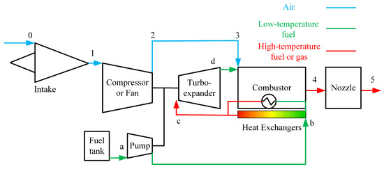
Figure 1.
Cycle scheme of the turboexpander engine.
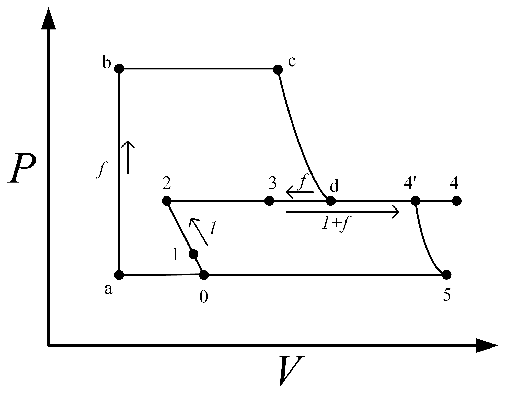
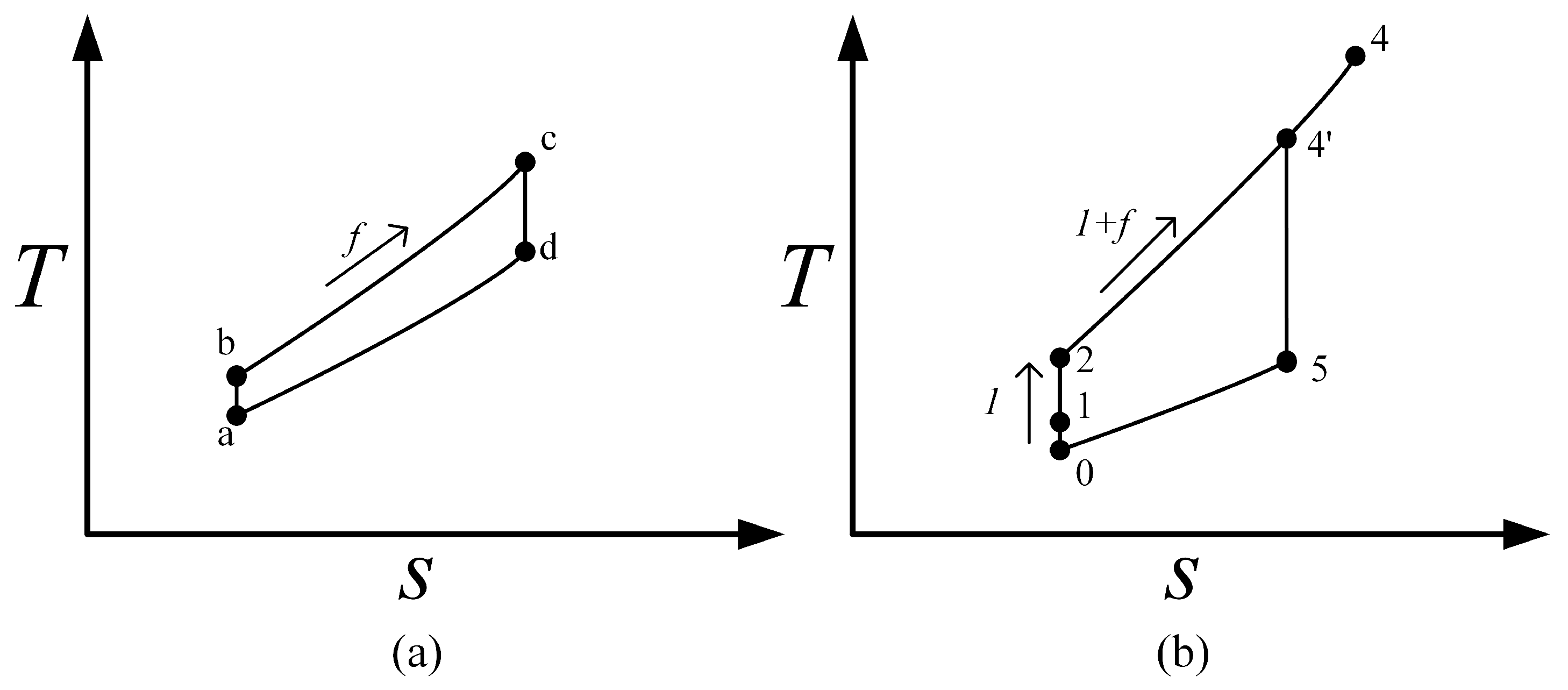
Figure 2 and Figure 3 are the P-V diagram and the T-s diagram of an ideal turboexpander engine cycle. The processes with Arabic numerals stand for air and gas, and the processes with lowercase English letters stand for fuel. In the figure, 0–1 is the compression process of the intake; 1–2 is the isentropic compression process of the compressor or fan; and 2–3 and d–3 show the mixing process of air and fuel in the front of combustor. Before mixing the fuel with air, a–b is the compression process of the pump, and b–c is the heating process of the cold side, where the heat is from the combustion in the combustor. After the mixing process, 3–4 stands for the combustion process; 4–4’ stands for the heat exchange on the hot side; and 4’–5 is the process that the gas ideally expands to ambient pressure through the nozzle and generates power.
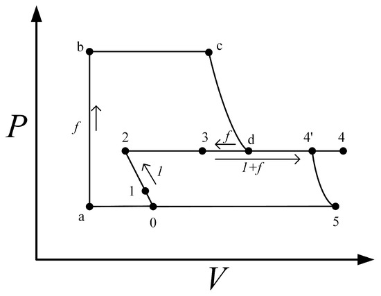
Figure 2.
Pressure–volume diagram of the turboexpander engine.

Figure 3.
Temperature-entropy diagram of the turboexpander engine: (a) fuel; (b) air and gas.
For liquid hydrogen- or liquid methane-fueled turboexpander engines, low-temperature liquid fuel can first pass through a pre-cooler in the inlet to reduce the total temperature of the incoming air flow and become heated, increase the fuel temperature, and then enter the heat exchanger to participate in heat transfer. In this way, the power demand of the compressor can be reduced and the total pressure ratio can be increased with the same turbine output power, thus improving the performance of the engine. However, the energy mass density of cryogenic liquid hydrogen or methane is low and requires a cryogenic pump, and the quality and frosting of the pre-cooler need to be considered, as mentioned in Section 1.
2.2. Feasibility of Turboexpander Engine
Like common turbine engines, the turboexpander engine also has very strict requirements on energy balance. However, the HED hydrocarbon fuel is regarded as a kind of undesirable working fluid for the turboexpander. This paper introduced the concept of the ‘feasibility of the engine’ to analyze the possibility of using HED hydrocarbon as the fuel for the turboexpander engine using an ideal thermodynamic model. The feasibility is a range of values for the engine parameters, which can ensure that the engine meets the same design requirement compared to the engines using other fuels. To evaluate the feasibility of the engine, an ideal thermodynamic model of the performance of the turboexpander engine was built. This model assumes that all the efficiencies are 1, there is no pressure loss in the engine, and the exhaust gas is ideally expanded to the ambient pressure in the nozzle. Moreover, because the power of liquid and gas pressurization is different, this model assumes that the pump power comes from outside the cycle rather than from the turbine.
As the specific impulse is important in wide-speed-range hypersonic vehicles, the feasibility analysis takes the gross specific impulse as the factor determining the feasibility of the engine. The ideal gross specific impulse of the engine can be given by Equation (1):
where g is the acceleration of gravity, f is the fuel-to-air ratio, is the constant pressure specific heat of the gas, is the total temperature of the combusted gas, is the specific heat ratio of the gas, and is the total pressure ratio of the compressor.
With the assumptions of neglecting the power of the pump and that efficiencies are set to 1, all the mechanical power generated by the turbine is transferred to the compressor or fan to pressurize the air, so the pressure ratio can be given by Equation (2):
where , , and are the constant pressure specific heat, the total temperature, and the specific heat ratio of the air, respectively; the subscript ‘1’ stands for the entrance of the compressor and subscript ‘c’ stands for the entrance of the turbine; and is the expansion ratio of the turbine. Equation (2) contains parameters of the characteristics of the turboexpander that affect its output power, which further affect the pressure ratio and performance. To simplify the analysis, the factor K is introduced to evaluate the capacity of the turboexpander to the output mechanism power, as shown in Equation (3):
The temperature of the combustor outlet reflects the total enthalpy of the gas in the combustor. In a turboexpander engine, part of the energy that is exchanged by the combustor through the heat exchanger finally returns to the combustor. If the total heat exchanging is and the work output of the turbine is , the total enthalpy of the fuel before the mixing process can be given by Equation (4) and the total enthalpy of air before the mixing process can be given by Equation (5):
where is the power of the compressor, which is equal to in the ideal thermodynamic model. Therefore, the total temperature of the combustor exit can be given by Equation (6):
where is the lower heating value (LHV) of the fuel, is the total specific enthalpy of the compressor outlet air, and is the constant pressure heat capacity of the combustor outlet gas. Substituting Equations (4) and (5) into Equation (6) and simplifying it, the effect of the amount of heat exchanged is eliminated, as shown in Equation (7), where the value of is neglected because it is usually much smaller than that of :
Let to simplify the equations. Substituting Equations (2) and (7) to Equation (1), the ideal specific impulse of the turboexpander engine can be given by Equation (8):
where represents the combined influence of the specific heat ratio of the combustor exhaust gas and the compressor inlet air, which is close to 1. For example, under ground conditions, for the HED hydrocarbon fuel is approximately 0.93. The value of f can be given by Equation (9):
where is the equivalence ratio and is the chemical stoichiometric ratio. When the vehicle accelerates, the engine often operates at a high equivalence ratio close to 1 for a higher thrust. Therefore, this model assumes that the engine works under the constant of 1. Then, is used to replace the fuel/air ratio to characterize the engine performance during acceleration instead of the fuel/air ratio.
The feasibility of the engine can be analyzed based on Equation (8). If the ideal specific impulse is too low, there is no advantage in using such fuels over others, or the engine cannot even run at other conditions. Equation (8) contains two groups of parameters: the working condition parameters and the engine design parameters. The parameters of the working condition include the equivalence ratio of the engine and the physical properties of the air before the compressor ( and ); the design parameters of the engine include the fuel type, which determines values of , , , , and , and the maximum inlet temperature and expansion ratio of the turbine. When the operating conditions of the engines are the same, the choice of fuel significantly influences the ideal performance of the engine. The higher the , , and of the fuel, the higher the specific impulse of the engine.
For turboexpander engines with different fuels, the main differences are the design parameters, mostly with regard to K. Hydrocarbon fuels used for aircraft propulsion systems have closed and , where generally does not exceed 48 MJ/kg, and is around 0.067, so the factor K can be considered as the theoretical minimum requirement for the turboexpander engine in the design . Rearranging and simplifying Equation (8), K can be expressed as Equation (10):
To further explain the feasibility of the HED hydrocarbon-fueled turboexpander engine, the ideal value of K at ground state is calculated. This is because when the engine is working under supersonic conditions, the pressurization of the intake can help the engine obtain a higher thrust to increase the specific impulse. Compared to other types of engines, it is more difficult for the turboexpander engine to gain enough thrust at the ground state than at other speeds. Under this condition, is 288.15 K through the US Standard Atmosphere model, and the of air at this temperature is 1004 J/kg/K, so the value of should be J/kg. Table 1 shows the value of for different fuels, and Figure 4 shows the minimum value of K needed to achieve the target performance for the turboexpander engine. The red asterisk and the star marks are the estimated values in the studies of [17,22], which used liquid methane and liquid hydrogen as fuel, respectively. The results show that increases with K, but the increase rate decreases. Compared to using hydrocarbon fuels, hydrogen-fueled expander engines can easily reach a higher K value, and for the same K, their theoretical specific impulse is higher, so the performance of hydrogen-fueled expander engines is much higher than that of hydrocarbon-fueled expander engines. The HED hydrocarbon-fueled engine and the methane-fueled engine have similar trends, but the theoretical specific impulse is lower. The use of liquid hydrogen for the pre-cooling scheme is also analyzed; the compressor inlet temperature is assumed to be 100 K lower than the environment temperature. The result indicates that the pre-cooling can significantly reduce the feasibility factor curve due to being reduced, so the cycle can obtain a higher specific impulse when the pre-cooler is used. Furthermore, ignorance of the efficiencies of the components, such as the turbine and compressor, caused the theoretical values of to be much higher than the test values. This method is helpful for the qualitative analysis of the performance of the turboexpander engines, but it has large errors and needs more detailed analyses.

Table 1.
Feasibility factor of the turboexpander engines with different fuel types.
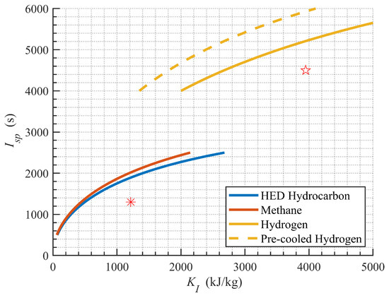
Figure 4.
Variation of the design specification of specific impulse with the minimum feasibility factor. Star and asterisk mean LH2 in Ref. [17] and pre-cooled methane in Ref. [22], respectively.
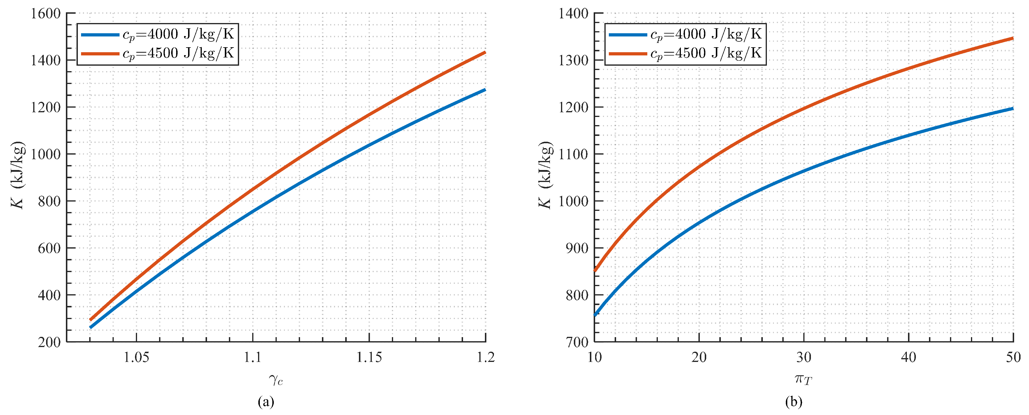
Although Figure 4 shows that the HED hydrocarbon-fueled engine has similar feasibility curves to the methane-fueled engine, the physical properties of the HED hydrocarbon fuels cause its K to be lower than the methane-fueled engine. The feasibility factor contains the high-temperature physical properties of the fuels and the inlet temperature and the expansion ratio of the turboexpander. As shown in Figure 5, and greatly affect the value of K. For a methane-fueled engine with of 10, K is 1068.17 kJ/kg, but the HED hydrocarbon-fueled engine with the same only has K of 559.36 kJ/kg, which is only 52.37% of the methane-fueled engine’s K. However, if can be increased to 50, the value of K can reach 903.21 kJ/kg, which is close to that of the methane-fueled engine. Liquid hydrocarbon fuels can be pressurized to very high pressures with relatively lower power use, and research has shown that an ultra-high expansion ratio turbine with an expansion ratio of 50 has an inner efficiency greater than 0.5 [30]. Therefore, it is feasible to achieve a decent performance using turbines with a high expansion ratio.
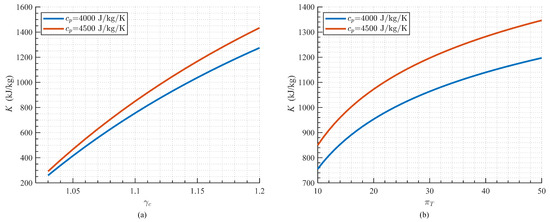
Figure 5.
Variation in the feasibility factor with (a) specific heat ratio of high-temperature HED hydrocarbon fuel and (b) turbine expansion ratio with the turbine inlet temperature of 1050 K.
3. Model of HED Hydrocarbon-Fueled Turboexpander Engine
To study the performance characteristics and the influencing factors of the HED hydrocarbon-fueled turboexpander engine, the thermodynamic model needs to be built.
3.1. Intake
The intake can reduce the speed of the incoming airflow to satisfy the inlet requirement of the fan or compressor, and this process is accompanied by flow losses. The mass flow capture coefficient and the total pressure recovery coefficient are the main parameters of intake performance. The of supersonic intake is 0.97 to 0.99 at subsonic speed, and its value for the supersonic condition is given by the equation according to the US military standard MIL-E-5008B [31] shown in Equation (11):
Then, the total pressure of the fan inlet can be given by Equation (12), and the temperature is the stagnation temperature under the current speed:
3.2. Turbomachinery
The power requirement of the fuel pump is considered in the cycle analysis. In addition to the energy balance, there is also the turning speed balance and the pressure balance. The balance of the turning speed depends on the components’ design; the thermodynamic analysis does not consider it. Let the injection pressure difference be ; then, the outlet pressure of the pump according to the pressure balance can be given by Equation (13):
where is the total pressure recovery of the fuel in the heat exchanger. Also, due to the work balance limitation, iterative calculation is needed as shown in Figure 6 [22]. The input design parameters include the design expansion ratio of the turboexpander and the fuel type, and non-dimensional parameters include the coefficients and efficiencies of each component. Based on the calculated fan pressure ratio , the pressure and temperature of fan outlets and can be obtained. Furthermore, the power of the fuel pump, fan, and turboexpander can be calculated by Equation (14) to Equation (16) [32]:
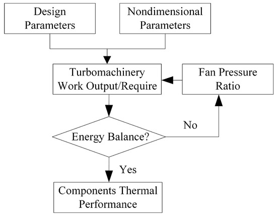
Figure 6.
Iterative calculation process of parameters for the turbomachinery component.
3.3. Fuel
As another important parameter in Figure 6, the physical properties for different types of fuel are very complex. Due to the insufficient research on the thermodynamic properties of cracked endothermic hydrocarbon fuel, this study estimated the constant pressure capacity and the specific heat ratio by the conversion rate of the gas state and the fractions of the cracked product in the literature [33], which are shown in Equations (17)–(19). is the mass of the gas product, and is the total mass of the fuel feed in the cracking experiment. and are the mole fraction and of the species i in the product, respectively. R is the ideal gas constant, where the value is 8.3145 J/mol, and is the average molar mass of the product:
of endothermic fuel varies with residence time, pressure, and temperature. For the convenience of analysis, this paper used the method of linear interpolation to calculate the physical properties of fuel cracking vapor and neglected the influence of residence time.
3.4. Heat Exchanger
This analysis assumed that the total temperature of the turboexpander inlet can be made constant by controlling the combustion organization and the heat-exchanging area. The pressure at the heat exchanger outlet can be given by Equation (20), and the heat exchanged energy can be given by Equation (21), where is the heat exchange effectiveness:
The is the ratio of the actual heat received by the fuel from the heat exchanger and the heat released to the heat exchanger from the combustor [22,34]. This article assumes that heat not absorbed by the fuel from the combustor is transferred outside of the cycle, as shown in Equation (22):
3.5. Combustor
Thermodynamic analysis of aircraft engines generally neglects the enthalpy of the injected fuel. Because the temperature and mass flow rate of the fuel are small, it hardly changes the temperature of the combustor [35]. However, in the turboexpander engine, the fuel temperature at the turbine outlet is still high, so its enthalpy is considered in the analysis. The energy of the fuel at the inlet of the combustor is the difference between the total heat absorbed by the fuel in the heat exchanger and the heat output by the turbine, which is ; then, the temperature of the combustor outlet can be given by Equation (23):
where is the combustion efficiency, and is interactively calculated by the chemical equilibrium and . The combustor outlet pressure is given by Equation (24):
where is the total pressure recovery coefficient of the combustor.
3.6. Nozzle and Performance
The nozzle can generate thrust by accelerating the high-temperature gas from the combustor. This paper assumes that the turboexpander engine nozzle uses a variable-geometry nozzle to ensure the wide-speed-range performance of the engine and so that the gas can ideally expand in the nozzle. The exhaust speed can be given by Equation (25):
where is the total pressure recovery coefficient of the nozzle and is the static pressure of the ambient air.
For engines aimed at the acceleration process of wide-speed-range hypersonic vehicles, the specific impulse and the specific thrust are the two most important parameters. An engine cycle with a high specific thrust means that the thrust per unit of capture area is higher, which can reduce the size of the engine, thereby reducing the dead weight. A high specific impulse means that the engine can provide more thrust with less fuel consumption, and the aircraft still has more fuel reserves when it reaches the target speed. The specific thrust and specific impulse can be given by Equations (26) and (27):
4. Parametric Study
4.1. Cycle Parameters of Hydrocarbon-Fueled Turboexpander Engine
The analysis in Section 2.2 showed that the most important factor influencing the performance is K, which contains the design expansion ratio of the turboexpanders and the physical properties of the high-temperature fuel. Table 2 shows the properties of several typical HED hydrocarbon fuels at the temperature at which they have the highest gas product conversion rate. N-decane is a common substitute for aviation kerosene and has a high . The analysis of this product used the latest research by Yu from the Harbin Institute of Technology [36], which is close to the Ward PDD model [37]. EHF-851 is a kind of endothermic hydrocarbon fuel mixture; the literature does not provide specific components on this fuel, but it provides an average molecular mass of 147 g/mol, and the average molecular formula of is estimated [38]. RP-3 is also called China NO.3 aviation kerosene and is used in active thermal protection [39,40]. Because it has a high conversion rate and a high fraction of small-molecular products and olefin products, it has a specific heat ratio higher than that of other fuels. Methylcyclohexane (MCH) is another HED substitute fuel used in research. It showed decent thermodynamic properties in the study by Liu [41]. In addition to these normal fuels, exo-THD reformed by water steam is a special type of working fluid for the turboexpander [42]. This technology is commonly used to improve the heat sink in a regenerative cooling scramjet because of its high chemical heat sink. The product contains a high concentration of CO and , so the specific heat ratio is much higher than that of hydrocarbon fuel alone. This article will not discuss this in detail, because additional propellant water leads to a lower of the fuel and higher , so the specific impulse of the cycle would be significantly reduced.
Table 2.
Reviews of the gas properties of cracking products of hydrocarbon fuels.
The standard working condition for the parametric study referenced the design point of hydrogen-fueled turboexpander engine in [17], where the flight speed is Mach 2 and the altitude is 18,000 m. The pressure and temperature of the fuel tank are assumed to be 0.3 MPa and 300 K. Unless otherwise specified, it is assumed that the efficiencies of the oil pump, fan, and turbine in the rotating parts at the design point are 0.70, 0.86, and 0.80, respectively. Assuming that the heat exchange efficiency is 0.90, the total pressure loss in the heat exchanger is 10%, the combustion efficiency and the total pressure recovery coefficient of the combustor and the nozzle are both 0.95, and the combustion efficiency is also 0.95.
4.2. Influence of the Design Parameters
The design parameters are the most important influence factors for the performance of the turboexpander engine, where fuel selection, the inlet temperature, and the design expansion ratio of the turboexpander are the three main design parameters. First, the key parameters of the engine under Mach 2 working conditions when using different HED hydrocarbon fuels are shown in Table 3. The specific impulse and the specific thrust under the frozen hypothesis are also calculated. Except for EHF-851 that lacks data under frozen hypothesis, all other data are from the references in Section 4.1 and NIST Chemistry WebBook [36,39,40,41,43]. Here, is 50, and is 1050 K. As an endothermic hydrocarbon fuel, RP-3 has a higher , so its value of K is higher than others and even twice the value of the n-decane-fueled engine. The of MCH fuel is lower than that of RP-3 fuel, and the K is 31.5% lower than that of the RP-3-fueled engine. Because the of MCH fuel is much higher than RP-3 (8.81%), the MCH-fueled engine still has a slightly higher specific thrust than the RP-3-fueled engine. Under the frozen hypothesis, values are about 4∼9% lower than the results considering fuel cracking.
Table 3.
Performance comparison with different HED hydrocarbon fuels.
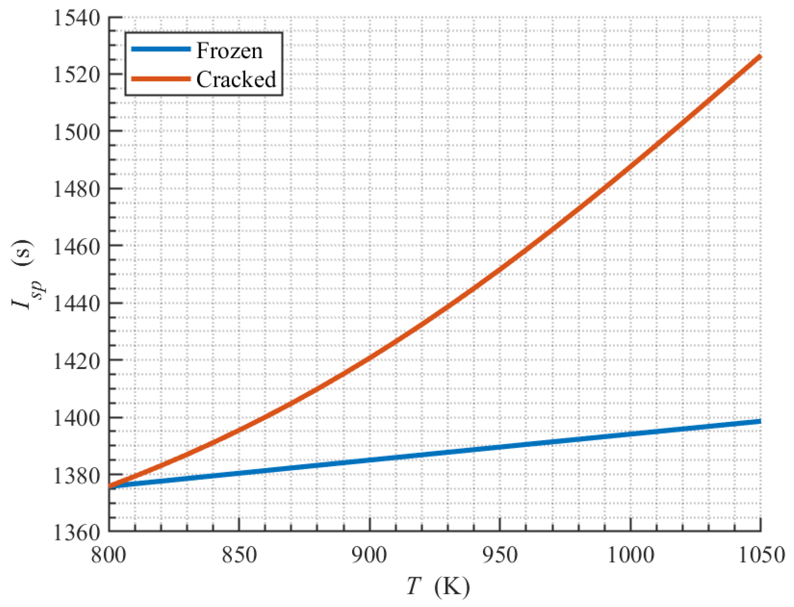
The inlet fuel temperature is another important parameter in the cycle design. The variation in performance with different values of is calculated using the RP-3 fuel, which is shown in Figure 7. Under the temperature range of 800 to 1050 K, the increase in leads to an increase in specific impulse, but the performance with a variable physical property condition is much higher than that of the frozen physical property condition. The curve in the frozen assumption is almost linear, and the specific impulse is 8.42% lower than the value when cracking is considered at 1050 K. This is because, in addition to the output power of the turboexpander, also influences the conversion ratio of the fuel. A higher can increase the conversion ratio and decrease the average molar mass of crack production, further increasing and to improve the engine performance.
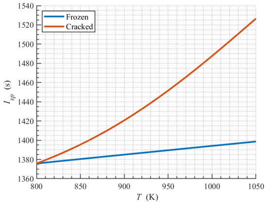
Figure 7.
Variation in specific impulse with the inlet temperature of the turboexpander.
The fuel type and decide the value of K, which is considered the most important design parameter of the cycle. When the fuel is selected and the inlet temperature of the turboexpander is constant, the design expansion ratio of the turboexpander and the working equivalence ratio are two influencing factors that should be considered. The variation in specific thrust and specific impulse with different values of and is shown in Figure 8. The higher the design pressure ratio of the expansion turbine, the greater the specific impulse. A higher thrust was also reflected in the influence of K on the cycle performance in a previous study. However, when increases, the performance gain from increasing becomes weaker. A slope change occurs in the region close to because the performance variation is different for rich-fuel or lean-fuel combustion. The extra fuel can increase slightly, but it cannot add more energy to the cycle. The average increase in the engine-specific impulse is 4.33% when increases from 10 to 40, but it only increases by 0.86% when increases from 50 to 80. Furthermore, an increase in reduces the specific impulse of the engine, but increases the specific thrust of the engine, and the performance of the engine is highly sensitive to it. Within the range of variation in the engine equivalence ratio of ±0.3, the average fluctuation of the specific impulse is 9.40%, and the specific thrust is ±29.44%. This is because a change in the equivalence ratio of the engine will directly affect the working ability of the turbine and increase the total pressure ratio and thrust of the engine.
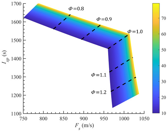
Figure 8.
Variation in specific impulse and specific thrust with different turbine expansion ratios and equivalence ratios.
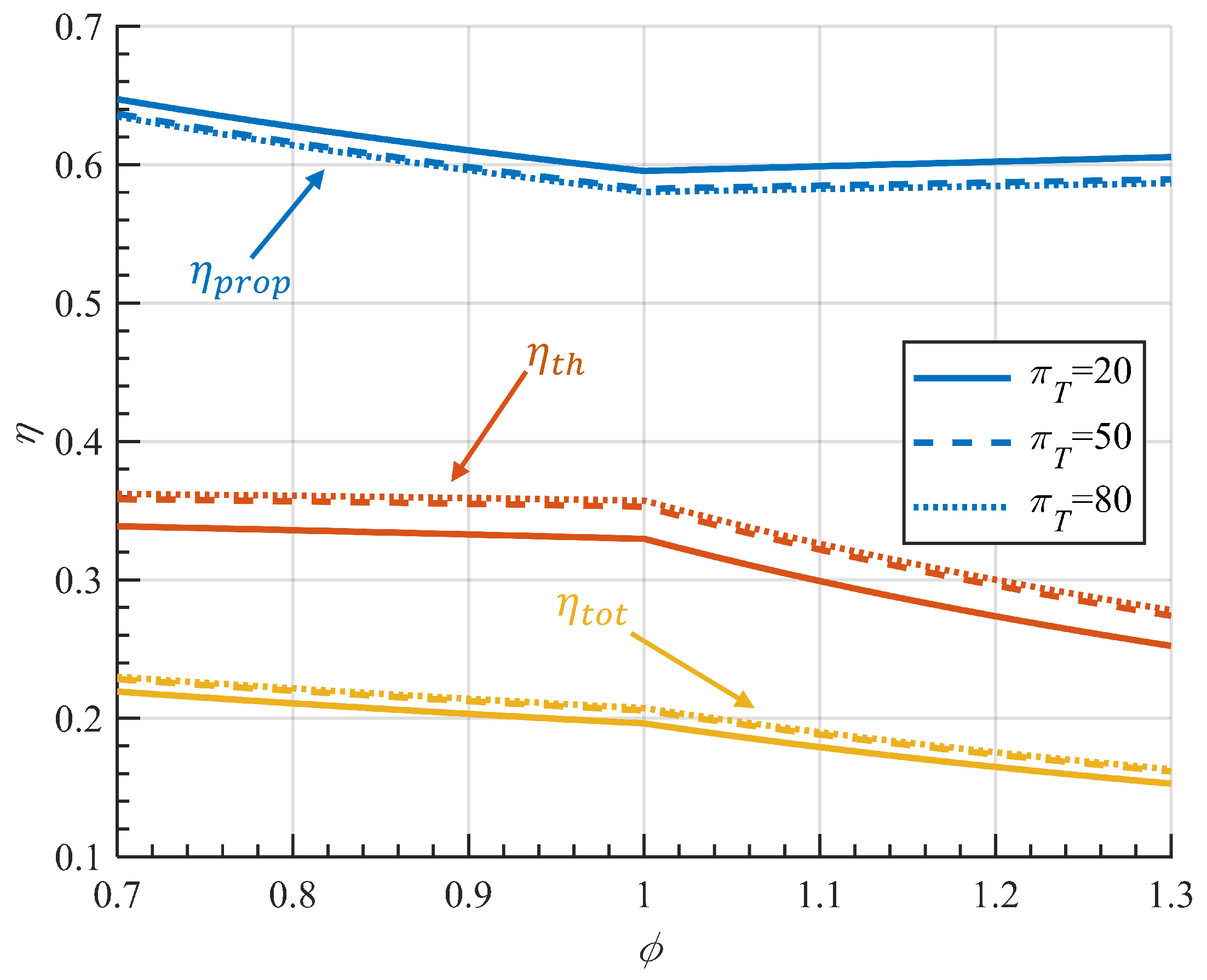
Figure 9 shows the variation in key engine efficiency under the reference condition. The propulsive efficiency is approximately 0.60, and it decreases first and then increases slowly after . The thermal efficiency is almost the same under lean-fuel conditions and decreases under rich-fuel conditions. As a result, the total efficiency of the engine with a of 20 decreases from 0.22 to 0.20 when increases from 0.7 to 1.0, and then decreases to 0.15 when increases to 1.3. Furthermore, increasing the turbine expansion ratio can improve the total efficiency, but the increase is very small in a high turbine expansion ratio. The variation in efficiency also explains the reason for the slope change at the stoichiometric point shown in Figure 8.
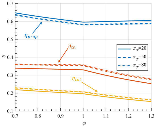
Figure 9.
Variation in propulsive, thermal, and global efficiencies with the equivalence ratios.
Although the design can use a high-expansion-ratio turbine to compensate for the lack of working ability of the HED hydrocarbon fuel, the heat exchanger and turbine may be extremely difficult to design and manufacture. For example, if is 100, the outlet pressure of the fuel pump will be as high as 32.34 MPa, which is unrealistic. Therefore, the expansion ratio of the engine should be carefully chosen in the design. Since the hydrocarbon-fueled turboexpander engine aims at the low Mach number acceleration of the reusable hypersonic vehicle, the high specific impulse means that the engine is more fuel-efficient for a certain period of time. However, if the specific impulse of the engine is increased by reducing the equivalence ratio, the reduction in the specific thrust will lead to a lower thrust and acceleration of the vehicle, and more time will be wasted in this process, which has a negative effect on fuel consumption that may affect the payload mass.
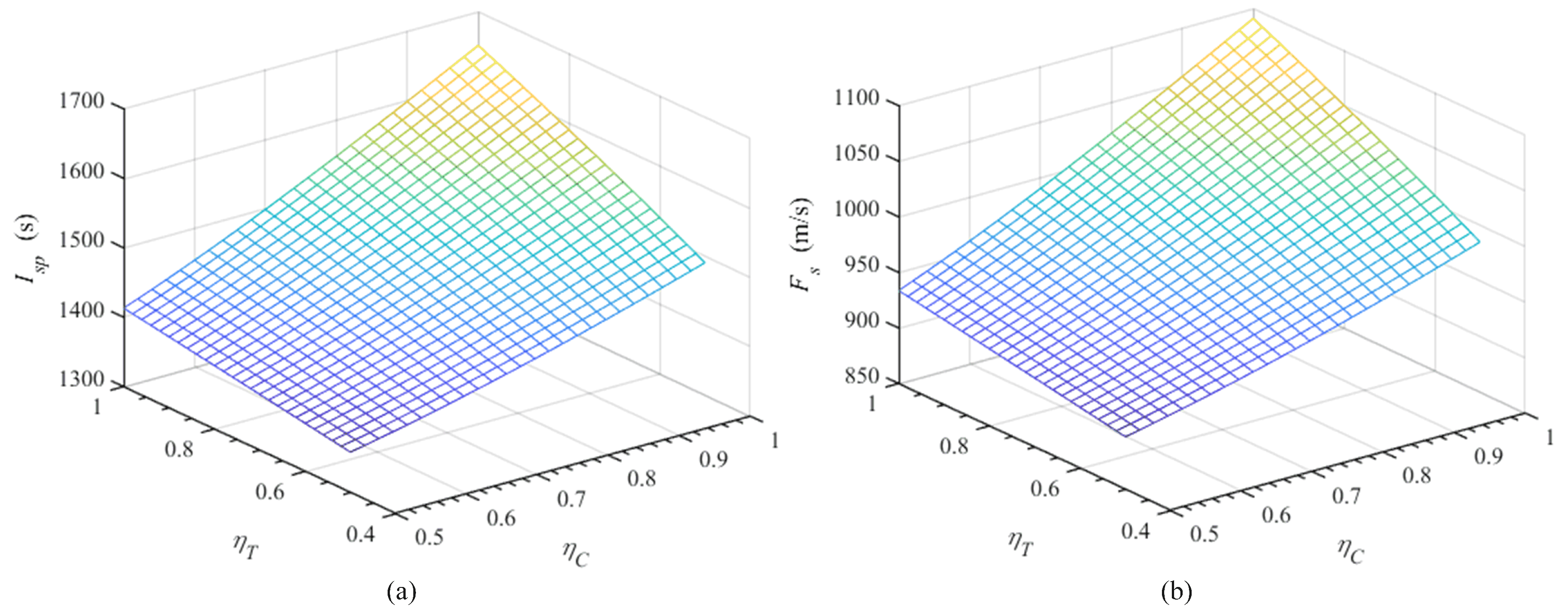
This engine uses a high-expansion-ratio turboexpander to increase the compressor power, which can cause the low efficiency of the turboexpander and the problem of the balance of rotation speed. Compressors with a low pressure ratio and high mass flow rate usually have a smaller rotational speed, but turboexpanders with a high expansion ratio and low mass flow rate have a high rotational speed. Therefore, the performances with different and under the Mach 2 condition have been evaluated, as shown in Figure 10, where the equivalence ratio is 1. and increase approximately linearly with the increasing . For the same , the increase rate of and is slightly higher at high . When and are 0.50, and are 1358.31 s and 897.50 m/s, respectively. However, under the Mach 0 condition, because the intake does not pressurize the air, the pressure ratio is lower and the engine performance is reduced. Under this condition, the impacts of and on performance are more evident. and are only 238.67 s and 157.70 m/s, respectively, while and are 0.50, which is only 15.40% of and , while and are 1. Therefore, the compressor and turboexpander efficiencies are important for engine performance. Especially at lower speeds, the design of the compressor and turboexpander can dramatically affect engine performance.
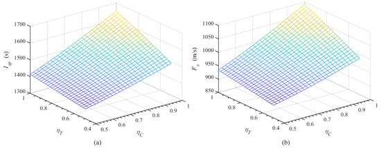
Figure 10.
The (a) specific impulse and (b) specific thrust of the engine with different efficiencies of compressor and turboexpander.
4.3. Sensitivity of Non-Dimensional Parameters of Turbomachinery and Heat Exchange
The design of the hydrocarbon fuel steam turboexpander and the low-pressure-ratio fan in this engine is a special combination compared with the turbomachinery system of ordinary aero-engines, so it is necessary to analyze the influence of the performance of the turbomachinery system on the performance of the engine. Moreover, the combustor needs a large heat exchange area to heat the fuel to about 1000 K, which will increase the flow pressure loss both in the combustion chamber and in the heat exchanger, so the influence of the pressure loss in the cycle is also analyzed. Table 4 shows the percentage change in key performance when the main coefficients and efficiencies changed by ±5%. The analysis shows that only the isentropic efficiency of the turbine has an impact on the output work of the turbine, which is 6.25%. This is because the decoupling of the compressor and the working medium of the turbine makes the work of the turbine relatively independent. The efficiency of the turboexpander and compressor has a greater impact on the pressure ratio of the compressor. The factor that has the greatest impact on engine performance is the speed loss coefficient of the engine nozzle because it directly affects the working ability of the gas in the nozzle. In addition, engine performance is also sensitive to changes in the efficiency of the compressor and the total pressure recovery coefficient of the combustor. In this engine cycle, the total pressure recovery of the heat exchanger, the heat exchange efficiency, and the efficiency of the pump have less influence on the engine performance, which is mainly because the mass flow rate of the working fluid in these components is much smaller than the air mass flow rate when the equivalence ratio is near 1.
Table 4.
Sensitivity analysis of nondimensional parameters of the turbomachinery and the heat exchange process.
4.4. Full-Range Performance
As the dual-mode scramjet engine is regarded as the best solution for SSTO vehicles between Mach 2/3 and Mach 12 or even higher speeds [35], the engine combined with the dual-mode scramjet engine can obtain good performance in Mach 0∼3. Therefore, the performance of the hydrocarbon-fueled turboexpander engine in Mach 0∼3 was analyzed.
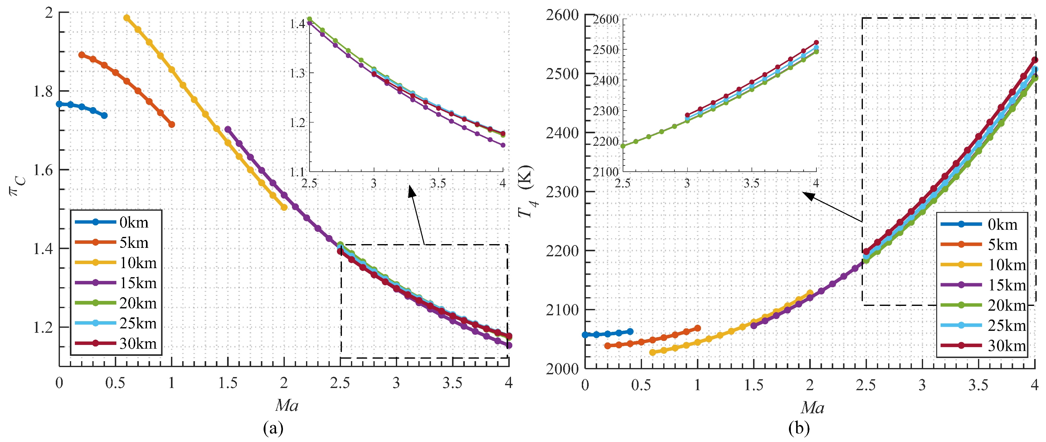
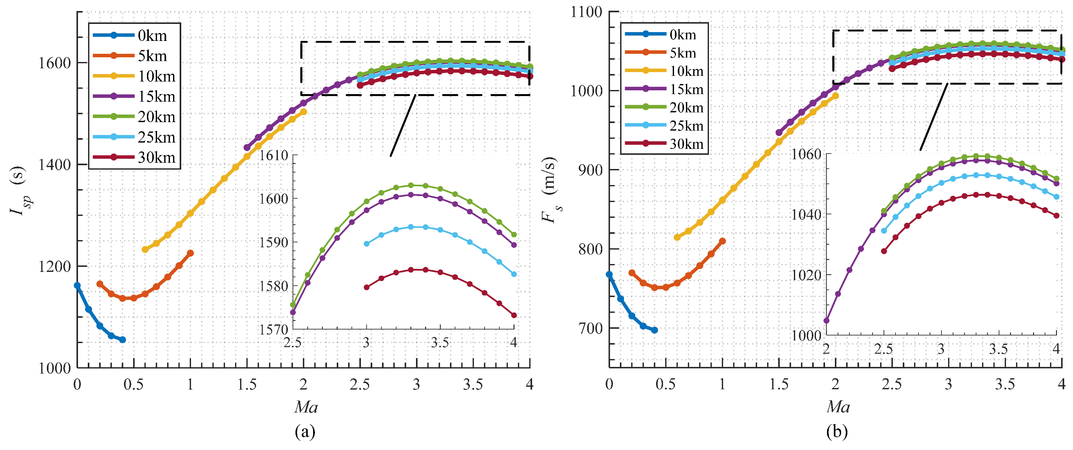
The engine performance changes at different Mach numbers are shown in Figure 11 and Figure 12. The specific impulse and specific thrust of the engine have the same trend, and they are lower at subsonic speed and reach the lowest at Mach 0.6. The transition from subsonic to supersonic causes the discontinuity result at Mach 1, where the intake pressurized the incoming air to increase the total pressure and temperature, which will be further discussed later in the article. An increase in flight altitude can improve performance because the total enthalpy of the inlet air is reduced. In supersonic flight, the engine performance no longer increases with the increase in the flight altitude. Performance is the highest when the flight altitude is about 20 km, and the engine performance decreases slightly with the increase in the flight altitude. The specific output power of the turboexpander remains constant because the decoupling of the working fluid in the turbomachinery leads to the inlet air barely impacting the output power of the turbine. However, since the total temperature of the incoming flow increases when the engine flight speed increases, it is difficult for the turboexpander to pressurize the incoming air. Therefore, as shown in Figure 11, the total pressure ratio of the engine decreases with increasing Mach number. When the Mach number is low, the higher the flight altitude, the lower the total temperature of the incoming air, which is helpful to boost the engine compressor. However, when the Mach number is high, the performance of the engine does not change much with the change in flight altitude because the aircraft enters the stratosphere, where the incoming air temperature does not change much. Furthermore, since the total temperature and turbine pressure ratio of the turbine inlet fuel are the same in the cycle, the turbine output power is the same when the turbine’s isentropic efficiency is neglected, so the performance of this cycle changes less at high Mach numbers.
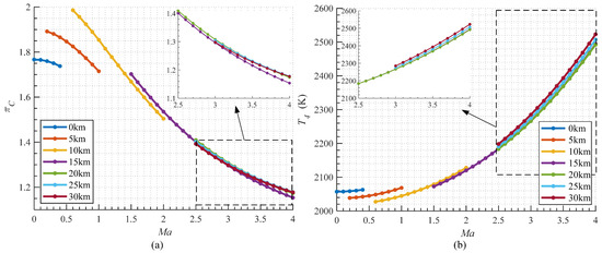
Figure 11.
Variation of (a) total pressure ratio and (b) combustor outlet temperature in different flight conditions.
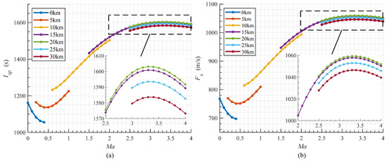
Figure 12.
Variation in (a) specific impulse and (b) specific thrust with different Mach numbers.
Since the engine needs to work in a wide range of speeds, the impact of the off-design point performance of components, like the intake and the compressor, cannot be ignored in the actual flight mission, but it is difficult to find the precise efficiencies of these components because they are largely dependent on their design. However, the approximate value or trend of the engine can be estimated through some assumptions. Assuming that the compressor operating line is similar to turbine engines, the flow capture coefficient and the compressor efficiency were estimated using Gasturb 12. The design point is still at Mach 2 and the flight trajectory is shown in Figure 13a. of the design point is 100 kg/s. The variation in the mass flow rate and the compressor efficiency in different Mach numbers is shown in Figure 13b. This paper assumes that the total pressure recovery coefficients of the combustor and the nozzle are constant, and the efficiency change in the pump and turboexpander are neglected.
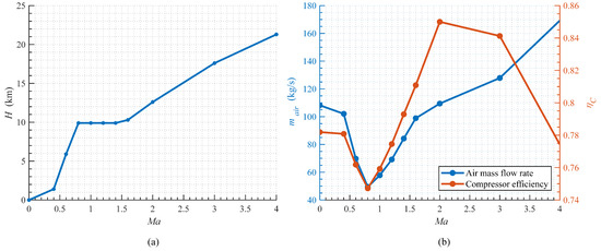
Figure 13.
The (a) flight trajectory of vehicle and (b) variation in the air mass flow rate and efficiency of compressor at different Mach numbers.
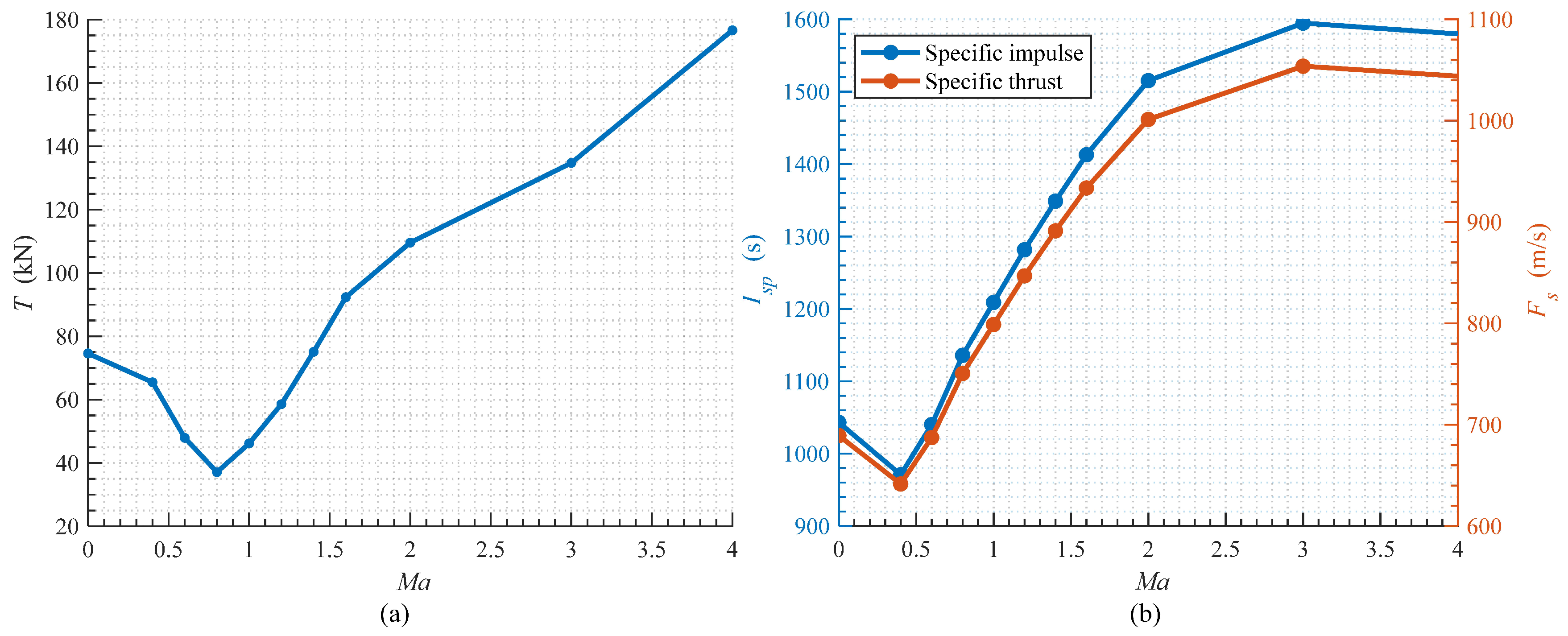
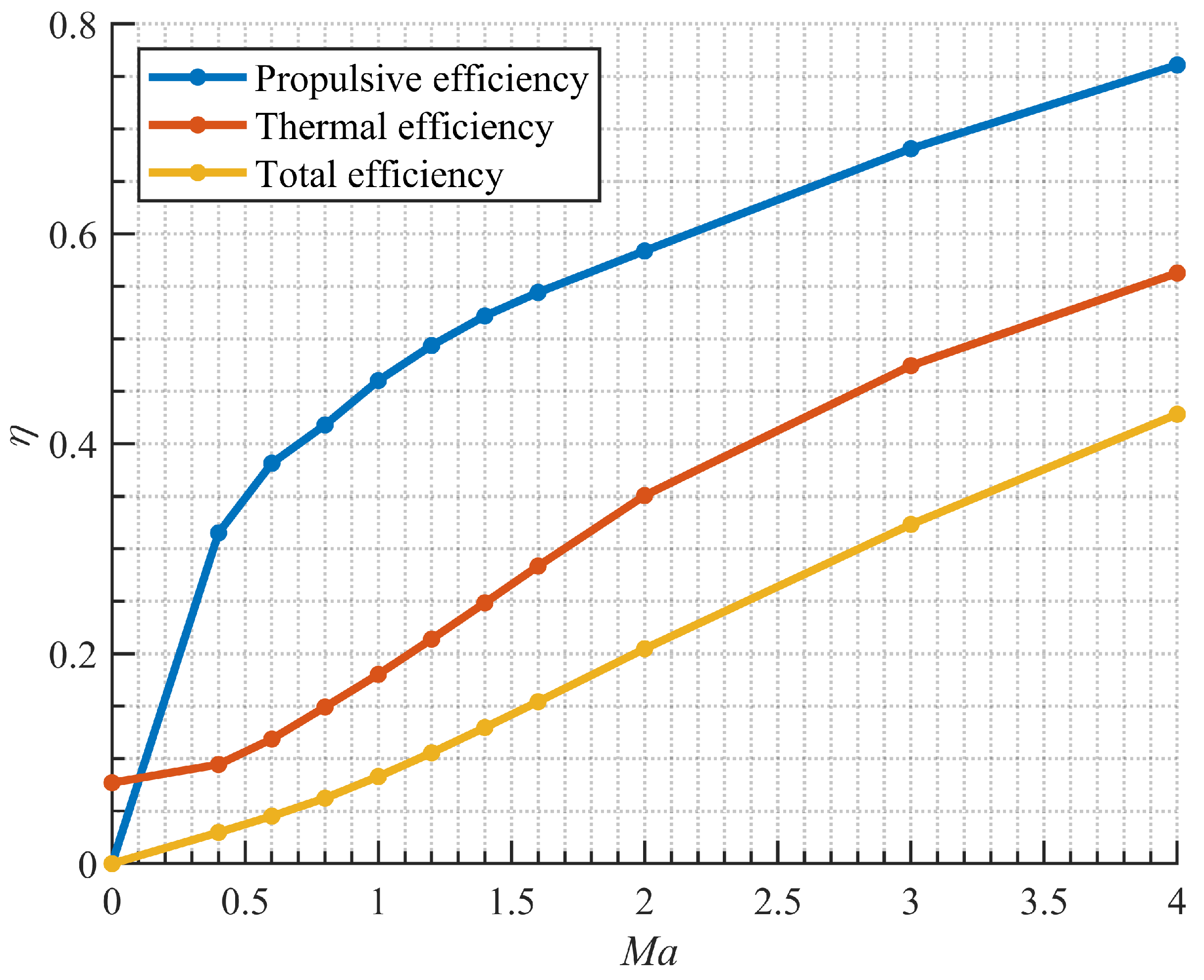
Figure 14 shows the predicted engine performance at Mach 0∼4. Due to the increase in , the thrust of the engine continues to increase after Mach 0.8. The and values have the same trend that decreases first until Mach 0.4 and then increases. The and values reach their highest points at Mach 3, and the values are 1594.80 s and 1053.76 m/s, respectively. After that, and decrease due to a large drop in compressor efficiency. Under the ground condition, and are 1043.17 s and 689.27 m/s, respectively. Figure 15 shows the variation in engine efficiency with Mach numbers, where propulsive, thermal, and total efficiency increase with increasing Mach numbers. The thermal efficiency is 0.077 at the ground, and the propulsive, thermal, and total efficiency are 0.76, 0.56, and 0.43 at Mach 4, respectively.
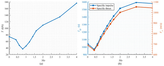
Figure 14.
The (a) thrust and the (b) specific impulse and specific thrust of the engine in a typical flight trajectory.
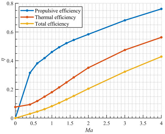
Figure 15.
Variation in engine efficiency with Mach numbers.
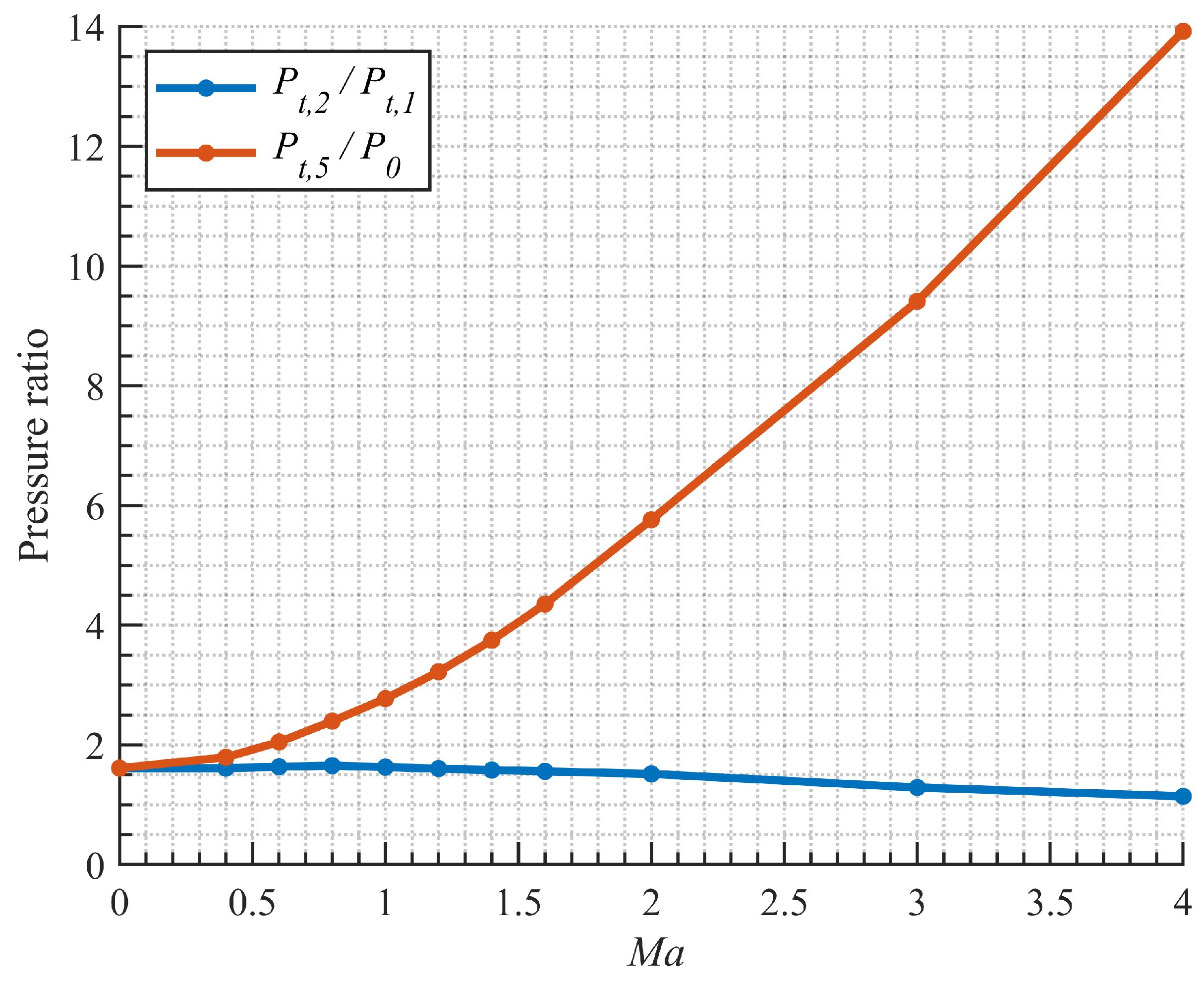
The reason why the performance of the engine increases at supersonic speeds can also be found in the variation of the pressure ratios shown in Figure 16. The compressor’s total pressure ratio first increases to a maximum value of 1.65 at Mach 0.8 from 1.61 at Mach 0, and then decreases as the Mach number increases. In supersonic flight, the incoming air obtains a high total pressure ratio due to the shock waves at the intake system. Although the compressor total pressure ratio decreases, the pressure ratio of the nozzle still increases significantly with increasing Mach number, and the engine performance increases. When the flight speed exceeds Mach 3, the performance of the engine decreases due to the decrease in compressor efficiency.
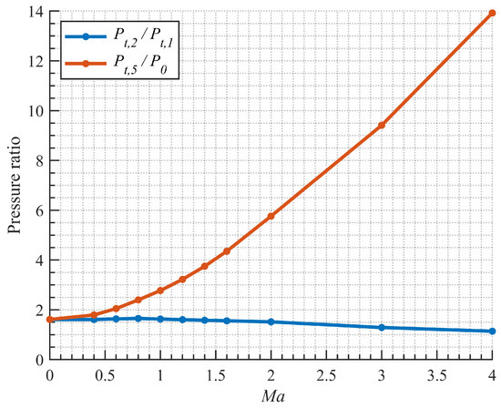
Figure 16.
Variation in pressure ratios of compressor and nozzle with different Mach numbers.
5. Discussion
Using the high conversion rate of endothermic hydrocarbon fuel at high temperatures can significantly improve the power output of the turboexpander engine. However, due to the lack of research on the cracked product of endothermic hydrocarbon fuels, this article used a simplified method to calculate the physical properties of the fuel and may cause errors. The analysis shows that the power output capacity of the turboexpander is the most important factor in increasing engine performance, so the inlet temperature and the design expansion ratio should be as high as possible. However, considering the injection pressure of the fuel in the combustor, a high expansion ratio requires high pressure in the heat exchanger, and the improvement in performance by increasing the expansion ratio of the turboexpander decreases with the increasing expansion ratio of the turboexpander. Therefore, high performance and structural realization need to be balanced, which depends on the design of the turboexpander. The design of turbomachinery components also impacts the results of the engine’s full-range performance, and the operating line of the engine may be different from that of the turbine engines in Gasturb; this can be further studied in future research.
According to thermodynamic analysis and parametric study, increasing the equivalence ratio can improve the specific thrust but decrease the specific impulse. For the consideration of fuel consumption, although the high specific impulse can decrease the fuel mass flow rate, the total fuel consumption may increase because the acceleration time is extended. Therefore, an appropriate equivalence ratio should be carefully chosen depending on the mission.
6. Conclusions
In conclusion, for the low-Mach-number acceleration target of reusable hypersonic vehicles and SSTO missions, the performance of HED hydrocarbon-fueled turboexpander engines was analyzed. The feasibility of turboexpander engines was analyzed using a simplified ideal cycle model, and the results suggested that a turboexpander with a high expansion ratio can make up for the lacking thermodynamic performance of HED hydrocarbon fuel. Parametric studies showed that using an endothermic hydrocarbon fuel such as RP-3 can improve engine performance because the mixture of its high-temperature cracked product has high constant-pressure-specific heat and a high specific heat ratio. A parametric study of the RP-3-fueled turboexpander engine was conducted; the results showed that increasing the expansion ratio of the turboexpander can increase the engine performance, and a higher equivalence ratio increases the specific thrust but decreases the specific impulse. The total pressure recovery coefficient of the combustor and the nozzle, and the compressor efficiency are the most significant non-dimensional parameters that influence engine performance, and the engine with an expansion ratio of 50 and a turboexpander inlet temperature of 1050 K has good performance in Mach 0∼4 with up to a specific impulse of 1594.80 s at Mach 3. Engine performance is the lowest under the Mach 0.8 condition, where the specific impulse is 970.92 s and the specific thrust is 641.53 m/s. Furthermore, the engine efficiency is higher in supersonic flight due to the compression of the intake.
The endothermic hydrocarbon-fueled turboexpander engine with a high turboexpander expansion ratio showed decent performance with the help of the high cracking conversion of the endothermic hydrocarbon fuel, which has reference implications for the propulsion system design of future aerospace vehicles. Further analysis can focus on the influence of the realistic performance of components, such as the impact of the high expansion ratio on the efficiency of the turboexpander and the capacity of heat exchanger. The dynamic characteristics of the cycle should be analyzed in future work, which is important for studying the starting and control methods of the engine.
Author Contributions
Conceptualization, W.B. and Y.W.; methodology, J.G. and J.Z.; software, J.G.; validation, W.S.; formal analysis, J.G.; writing, J.G.; visualization, Z.K.; supervision, W.B. and J.Z. All authors have read and agreed to the published version of the manuscript.
Funding
This research was funded by the National Natural Science Foundation of China (Grants No. 12102110) and the Program 1912.
Data Availability Statement
Data are contained within the article and the references.
Conflicts of Interest
The authors declare no conflict of interest.
Nomenclature
| Alphabetic letters | |
| constant-pressure heat capacity | |
| f | fuel-to-air ratio |
| chemical stoichiometric ratio | |
| F | thrust |
| specific thrust | |
| g | acceleration of gravity |
| h | specific enthalpy |
| H | altitude |
| lower heating value | |
| specific impulse | |
| K | turbine work output capacity |
| mass flow rate | |
| Mach number | |
| P | pressure |
| rate of heat exchange | |
| s | entropy |
| T | temperature |
| V | velocity |
| power of turbomachinery components | |
| Greek letters | |
| efficiency | |
| specific heat ratio | |
| pressure ratio | |
| total pressure recovery coefficient | |
| equivalence ratio | |
| air mass flow capture coefficient of the intake | |
| Subscripts | |
| B | combustor or burning process |
| C | compressor |
| parameter under frozen hypothesis | |
| heat exchanger | |
| injection | |
| I | ideal or theoretical value |
| inlet | |
| N | nozzle |
| propulsive | |
| P | pump |
| t | stagnation values |
| thermal | |
| total | |
| T | turboexpander |
| Symbols | |
| ATR | Air Turborocket |
| ATREX | Air Turboramjet with Expander |
| BOV | Balloon-Based Operation Vehicle |
| exo-THD | Exo-tetrahydrodicyclopentadiene |
| GG | Gas Generator |
| HED | High Energy Density |
| ISAS | Japanese Institute of Space and Astronautical Science |
| LHV | Lower Heating Value |
| MCH | Methylcyclohexane |
| PCTJ | Pre-Cooled Turbojet |
| PDC | Pulse Detonation Cycle |
| PFPMT | Pre-Cooled and Fuel-Rich Pre-Burned Mixed-Flow Turbofan |
| RBCC | Rocket-Based Combined Cycle |
| SSTO | Single Stage to Orbit |
| TBCC | Turbine-Based Combined Cycle |
References
- Zuo, F.Y.; Mölder, S. Hypersonic wavecatcher intakes and variable-geometry turbine based combined cycle engines. Prog. Aerosp. Sci. 2019, 106, 108–144. [Google Scholar] [CrossRef]
- Zhang, T.T.; Wang, Z.G.; Huang, W.; Chen, J.; Sun, M.B. The overall layout of rocket-based combined-cycle engines: A review. J. Zhejiang Univ.-Sci. A 2019, 20, 163–183. [Google Scholar] [CrossRef]
- Briggs, M.; Campbell, J.; Andrus, S.; Burgner, G. Synthesis and performance of an Air-TurboRamjet-propelled supersonictarget vehicle. In Proceedings of the 22nd Aerospace Sciences Meeting, Reno, NV, USA, 9–12 January 1984; p. 75. [Google Scholar] [CrossRef]
- Bussi, G.; Colasurdo, G.; Pastrone, D. Analysis of air-turborocket performance. J. Propuls. Power 1995, 11, 950–954. [Google Scholar] [CrossRef]
- Christensen, K. Air Turborocket/Vehicle Performance Comparison. J. Propuls. Power 1999, 15, 706–712. [Google Scholar] [CrossRef]
- Nan, X.; Liu, Y.; Ma, Y.; Ma, J. Thermodynamic process and operating characteristics of air turbo rocket engine. Acta Aerodyn. Sin. 2022, 40, 181–189. [Google Scholar] [CrossRef]
- Mizobata, K.; Kimura, H.; Sugiyama, H.; Sato, T.; Kobayashi, H. Conceptual Design of Flight Demonstrator Vehicles for the ATREX Engines. In Proceedings of the 12th AIAA International Space Planes and Hypersonic Systems and Technologies, Norfolk, VA, USA, 15–19 December 2003; p. 7028. [Google Scholar] [CrossRef]
- Sato, T.; Tanatsugu, N.; Hatta, H.; Goto, K.; Kobayashi, H.; Omi, J.; Tomike, J. Development study of the ATREX engine for TSTO spaceplane. In Proceedings of the 10th AIAA/NAL-NASDA-ISAS International Space Planes and Hypersonic Systems and Technologies Conference, Kyoto, Japan, 24–27 April 2001; p. 1839. [Google Scholar] [CrossRef]
- Fujita, K.; Tsuboi, N.; Sawai, S.; Kobayashi, H.; Miyaji, K.; Uchiyama, T. Aerodynamic Design of Balloon-Based Operation Vehicle for Precooled Turbojet Engine Demonstration. In Proceedings of the 15th AIAA International Space Planes and Hypersonic Systems and Technologies Conference, Dayton, OH, USA, 28 April–1 May 2008; p. 2658. [Google Scholar] [CrossRef]
- Taguchi, H.; Hongoh, M.; Kojima, T.; Saito, T. Mach 4 Performance Evaluation of Hypersonic Pre-Cooled Turbojet Engine. In Proceedings of the 22nd AIAA International Space Planes and Hypersonics Systems and Technologies Conference, Orlando, FL, USA, 17–19 September 2018; p. 5203. [Google Scholar] [CrossRef]
- Taguchi, H.; Kobayashi, H.; Kojima, T.; Ueno, A.; Hongoh, M.; Harada, K.; Aoki, T. Hypersonic Flight Experiment Plan of Pre-Cooled Turbojet Engine. In Proceedings of the 18th AIAA/3AF International Space Planes and Hypersonic Systems and Technologies Conference, Tours, France, 24–28 September 2012; p. 5840. [Google Scholar] [CrossRef]
- Taguchi, H.; Harada, K.; Kobayashi, H.; Hongoh, M.; Masaki, D.; Nishida, S. Mach 4 Simulating Experiment of Pre-Cooled Turbojet Engine Using Liquid Hydrogen. Aerospace 2022, 9, 39. [Google Scholar] [CrossRef]
- Fernandez-Villace, V.; Paniagua, G. Numerical Model of a Variable-Combined-Cycle Engine for Dual Subsonic and Supersonic Cruise. Energies 2013, 6, 839–870. [Google Scholar] [CrossRef]
- Tanbay, T.; Durmayaz, A. Energy, exergy and ecological analysis and multiobjective optimization of the hydrogen-fueled Scimitar engine with fixed nozzle geometry. Int. J. Hydrog. Energy 2022, 47, 19876–19887. [Google Scholar] [CrossRef]
- Fernandez-Villace, V.; Paniagua, G. Simulation of a Variable-Combined-Cycle Engine for Dual Subsonic and Supersonic Cruise. In Proceedings of the 47th AIAA/ASME/SAE/ASEE Joint Propulsion Conference & Exhibit, San Diego, CA, USA, 31 July–3 August 2011. [Google Scholar] [CrossRef]
- Li, J.; Liu, K.; Gao, Y.; Liu, S.; Wang, W.; Liu, Y. Combustion Characteristics Experimental Study of Solid Hydrocarbon Propellant for Air-Turbo Rocket. J. Propuls. Power 2018, 34, 1198–1205. [Google Scholar] [CrossRef]
- Rodríguez-Miranda, I.; Fernández-Villacé, V.; Paniagua, G. Modeling, Analysis, and Optimization of the Air-Turborocket Expander Engine. J. Propuls. Power 2013, 29, 1266–1273. [Google Scholar] [CrossRef]
- Zhao, W.; Huang, C.; Zhao, Q.; Ma, Y.; Xu, J. Performance analysis of a pre-cooled and fuel-rich pre-burned mixed-flow turbofan cycle for high speed vehicles. Energy 2018, 154, 96–109. [Google Scholar] [CrossRef]
- Yao, Z.; Guo, Y.; Liu, M.; Zhou, S. Performance study of a pre-cooled turbo-rocket combined engine under a wide Mach number of 0∼5. Case Stud. Therm. Eng. 2022, 38, 102307. [Google Scholar] [CrossRef]
- Yao, Z.; Guo, Y.; Niu, J.; Jin, Z.; Yu, T.; Guo, B.; Pu, W.; Wei, X.; Jin, F.; Li, B.; et al. Optimization Design of the NUAA-PTRE: A New Pre-Cooled Turbine Engine Adapting to 0∼5 Mach Number. Aerospace 2023, 10, 185. [Google Scholar] [CrossRef]
- Luo, S.; Sun, Y.; Song, J.; Liu, J. Performance analysis of a hybrid pulse detonation engine using liquid hydrogen as fuel. Int. J. Hydrogen Energy 2022, 47, 21537–21551. [Google Scholar] [CrossRef]
- Luo, J.; Yang, S.; Zhang, J.; Li, J.; Xiang, Z.; Zhang, W. Performance Analysis of Expander Cycle Air-Turborocket with Methane-Precooled. J. Propuls. Technol. 2021, 42, 1964–1975. [Google Scholar] [CrossRef]
- Heiser, W.H.; Pratt, D.T. Hypersonic Airbreathing Propulsion; AIAA: Reston, VA, USA, 1994. [Google Scholar]
- Li, H.; Qin, J.; Jiang, Y.; Zhou, W.; Bao, W.; Huang, H. Experimental study on the thermodynamic characteristics of the high temperature hydrocarbon fuel in the cooling channel of the hypersonic vehicle. Acta Astronaut. 2019, 155, 63–79. [Google Scholar] [CrossRef]
- Xu, Q.; Li, H.; Feng, Y.; Li, X.; Ling, C.; Zhou, C.; Qin, J. Dynamic thermo-physical characteristics of high temperature gaseous hydrocarbon fuel thermal power generation for regeneratively cooled hypersonic propulsion system. Energy 2020, 211, 118722. [Google Scholar] [CrossRef]
- Zhang, D.; Qin, J.; Feng, Y.; Ren, F.; Bao, W. Performance evaluation of power generation system with fuel vapor turbine onboard hydrocarbon fueled scramjets. Energy 2014, 77, 732–741. [Google Scholar] [CrossRef]
- Qin, J.; Bao, W.; Zhang, S.; Zhou, W. Comparison during a scramjet regenerative cooling and recooling cycle. J. Thermophys. Heat Transf. 2012, 26, 612–618. [Google Scholar] [CrossRef]
- Li, H.; Qin, J.; Jiang, Y.; Zhang, D.; Cheng, K.; Bao, W.; Huang, H. Experimental and theoretical investigation of power generation scheme driven by thermal cracked gaseous hydrocarbon fuel for hypersonic vehicle. Energy Convers. Manag. 2018, 165, 334–343. [Google Scholar] [CrossRef]
- Li, H.; Qin, J.; Bao, W.; Huang, H. Performance improvement of gaseous hydrocarbon fuel driven thermal power generation systems for hypersonic vehicles. Energy Convers. Manag. 2019, 199, 111949. [Google Scholar] [CrossRef]
- Zhang, R. Aerodynamic Performance Research on Ultra High Expansion Ratio Turbine (in Chinese). Master’s Thesis, Harbin Institute of Technology, Harbin, China, 2014. [Google Scholar]
- Waters, M.H. Turbojet-Ramjet Propulsion System for All-Body Hypersonic Aircraft; National Aeronautics and Space Administration: Washington, DC, USA, 1971.
- Zhang, R. Research on Air Turbo Ramjet Expander Engine Component Matching and Performance Optimization (in Chinese). Ph.D. Thesis, University of Chinese Academy of Sciences, Beijing, China, 2018. [Google Scholar]
- Liu, G.; Jia, X.; Tian, Y.; Gong, S.; Wang, L.; Zhang, X. Preparations and remarkable catalytic cracking performances of Pt@ FGS/JP-10 nanofluids. Fuel 2019, 252, 228–237. [Google Scholar] [CrossRef]
- Shah, R.K.; Sekulic, D.P. Fundamentals of Heat Exchanger Design; John Wiley & Sons: Hoboken, NJ, USA, 2003. [Google Scholar]
- Wang, Y.; Cheng, K.; Tang, J.; Liu, X.; Bao, W. Analysis of the maximum flight Mach number of hydrocarbon-fueled scramjet engines under the flight cruising constraint and the combustor cooling requirement. Aerosp. Sci. Technol. 2020, 98, 105594. [Google Scholar] [CrossRef]
- Yu, W.; Zhou, W.; Jia, Z.; Han, Z. Characteristics of scramjet regenerative cooling with endothermic chemical reactions. Acta Astronaut. 2022, 195, 1–11. [Google Scholar] [CrossRef]
- Ward, T.A.; Ervin, J.S.; Zabarnick, S.; Shafer, L. Pressure Effects on Flowing Mildly-Cracked n-Decane. J. Propuls. Power 2005, 21, 344–355. [Google Scholar] [CrossRef]
- Li, Y.; Jin, B.; Zhang, X.; Liu, G. Pyrolysis and heat sink of an endothermic hydrocarbon fuel EHF-851. J. Anal. Appl. Pyrolysis 2021, 155, 105084. [Google Scholar] [CrossRef]
- Zhong, F.; Fan, X.; Yu, G.; Li, J.; Sung, C.J. Thermal Cracking and Heat Sink Capacity of Aviation Kerosene Under Supercritical Conditions. J. Thermophys. Heat Transf. 2011, 25, 450–456. [Google Scholar] [CrossRef]
- Fu, Y.; Huang, H.; Wen, J.; Xu, G.; Zhao, W. Experimental investigation on convective heat transfer of supercritical RP-3 in vertical miniature tubes with various diameters. Int. J. Heat Mass Transf. 2017, 112, 814–824. [Google Scholar] [CrossRef]
- Liu, B.; Wang, Z.; Zhu, Q.; Li, X.; Wang, J. Performance of Pt/ZrO2–TiO2–Al2O3 and coke deposition during methylcyclohexane catalytic cracking. Fuel 2017, 200, 387–394. [Google Scholar] [CrossRef]
- Zheng, Q.; Xiao, Z.; Xu, J.; Pan, L.; Zhang, X.; Zou, J.J. Catalytic steam reforming and heat sink of high-energy-density fuels: Correlation of reaction behaviors with molecular structures. Fuel 2021, 286, 119371. [Google Scholar] [CrossRef]
- Linstrom, P.; Mallard, W.G. NIST Chemistry WebBook, NIST Standard Reference Database Number 69; National Institute of Standards and Technology: Gaithersburg, MD, USA, 2023.


Disclaimer/Publisher’s Note: The statements, opinions and data contained in all publications are solely those of the individual author(s) and contributor(s) and not of MDPI and/or the editor(s). MDPI and/or the editor(s) disclaim responsibility for any injury to people or property resulting from any ideas, methods, instructions or products referred to in the content. |
© 2023 by the authors. Licensee MDPI, Basel, Switzerland. This article is an open access article distributed under the terms and conditions of the Creative Commons Attribution (CC BY) license (https://creativecommons.org/licenses/by/4.0/).