Article

Energy Analysis for Solar-Powered Unmanned Aerial Vehicle under Static Soaring

School of Aeronautic Science and Engineering, Beihang University, Beijing 100191, China
*
Author to whom correspondence should be addressed.
Aerospace 2023, 10(9), 779; https://doi.org/10.3390/aerospace10090779
Submission received: 13 July 2023 / Revised: 23 August 2023 / Accepted: 24 August 2023 / Published: 31 August 2023

Abstract

:
Endurance is a critical factor for solar-powered unmanned aerial vehicles (SUAVs). Taking inspiration from birds, SUAVs have the ability to harvest extra energy from atmospheric thermal updrafts to extend their endurance. Though recent research has mainly focused on estimating the characteristics of thermal updrafts, there is a noticeable dearth of studies investigating the energy performance of SUAVs during soaring under different conditions. To begin with, this work establishes a thermal updraft and SUAV energy model. In addition, it introduces an integrated guidance and control process to achieve static soaring within thermal for SUAVs. Numerical simulations are implemented to analyze the electric energy performance at different solar irradiation levels, SUAV velocities and thermal strengths. Several remarkable conclusions are drawn from the simulations, which could provide significant insights for SUAVs to further exploit thermal energy.

1. Introduction

The endurance of unmanned aerial vehicles (UAVs) is a key element to their performing and completing missions successfully. Since solar power is considered renewable, it has potential as a power source for long-distance flights in UAVs [1]. Some studies have contributed to improving the applications of SUAVs, such as surveillance [2], eavesdropping [3] and communication [4]. However, both the solar panel area and the battery capacity impose restrictions on the endurance of SUAVs. For this reason, SUAV power system optimization plays a significant role in the continuation of its journey [5]. In addition, taking advantage of the flight environment is another way to acquire extra energy for SUAVs. Atmospheric thermal, also called updraft, occurs when heating changes at the surface of the Earth, and the air near the ground becomes less dense than the surrounding air [6]. Birds can soar with thermal, which may help humans on small fixed-wing aircrafts obtain energy by soaring as well. Allen [6] developed a thermal model that describes the location, radius and strength of the updraft in a three-dimensional space.
The most important procedure for SUAVs being able to soar is to estimate the location of the thermal updraft. However, it is difficult to predict thermals directly through any onboard sensor. In reference to different principles, several methods have been discussed to achieve soaring through thermal updrafts, such as the optimal control-based method [7,8], total energy-based feedback control [9,10], the Kalman filter-based technique [11,12] and a reinforcement learning-based algorithm [13,14]. By adopting these methods, an SUAV is able to climb to a higher altitude with little energy consumption and then glide for a distance towards its destination.
Several experiments have been carried out to discuss the application of soaring for UAVs. Emmanuel Schermann et al. [15] established a stochastic optimization problem and solved an optimal trajectory to improve surveillance ability through thermals. Paolo Gunetti et al. [16] proposed a mission management system combined with autonomous soaring with traditional control to generate flight plans automatically. Due to the risk of collision for multi-UAVs, Cobano et al. [17] used the rapidly exploring random trees algorithm to avoid collision during cooperative thermal detection. Klas Andersson et al. [18] tested cooperative soaring by multiple UAVs and found the restriction that the cooperation was impaired by separation and flight altitude.
SUAVs could gain advantages from static soaring through thermal as well. SUAVs differ from electric UAVs in endurance performance, which depends not only on the battery capacity but is also determined by the solar irradiance. The solar power generation calculation is complicated and is influenced by the date, time, location and attitude. Considering the restrictions of the flight environment and the SUAV’s parameters, Mateja et al. [19] developed an energy system model for simulation. Peciak et al. [20] presented the application of a solar cell for a vertical take-off and landing (VTOL) UAV, analyzing the endurance performance of the UAV during continuous flight. Huang et al. [21] presented a path-planning procedure to calculate the optimal energy path for a SUAV while tracking a fixed target in 3D space. Wu and Wang [22] analyzed the effect of different latitudes and longitudes on solar energy generation and put forward an energy endurance map to evaluate the SUAV’s endurance performance. Daniel J. Edwards et al. [23] considered the net power for SUAVs during continuous circular flight and solved the optimal bank angle to maximize the power input from both solar cells and thermal updraft. Furthermore, scholars have improved several optimization algorithms to achieve the maximum energy for different missions, such as single SUAV target-tracking problems [24], multiple SUAV target tracking [25] and path planning [26]. Finally, these works investigate the methods for and performance of SUAV endurance extension through wind field [27] and thermal updraft data [28].
Recent research focuses on thermal location perception and the utilization of soaring to enhance endurance for UAVs. Few works have explored the electric energy storage in SUAVs during the soaring and gliding phases under different conditions.
Static soaring has been widely adopted for low-altitude fixed-wing UAVs, but the drone’s endurance could be further enhanced by combining thermal updraft and solar energy. A great number of studies focus on the maximum energy in the SUAV path-planning problem, and a few works investigate the advantages of SUAV static soaring and its influences. Despite discussing the effect of different bank angles on the net power of SUAVs during soaring, further investigation into the effects of other parameters on the variation in electric energy is also necessary. Several articles discuss using the climbing altitude to evaluate the amount of energy harvested from the atmospheric thermal. The energy conversion during the gliding phase is not ignored, but this is not suitable for SUAVs. For these reasons, this paper aims to study the electric energy variation in SUAVs during soaring under different conditions. To begin with, we establish the required model involving thermal updraft, solar radiation, kinematics and energy of the SUAV. Moreover, a feedback control-based integrated method is adopted to guide the SUAV soaring in thermal. In addition, a simulation is executed to analyze the changes in electric energy during the soaring and gliding phases. The impact on solar radiation is compared with energy costs (SUAV velocity), soaring time (thermal strength) and gliding time (SUAV velocity). We also propose the concept of equivalent endurance to evaluate the energy that the SUAV harvests from thermal by soaring.
The rest of this paper is divided as follows. A corresponding model is built for simulation in Section 2. A brief soaring method and process for the SUAV are introduced in Section 3. Section 4 presents the simulation result for energy analysis during soaring under different conditions. Finally, Section 5 provides a conclusion for this work.

2. Problem Formulation

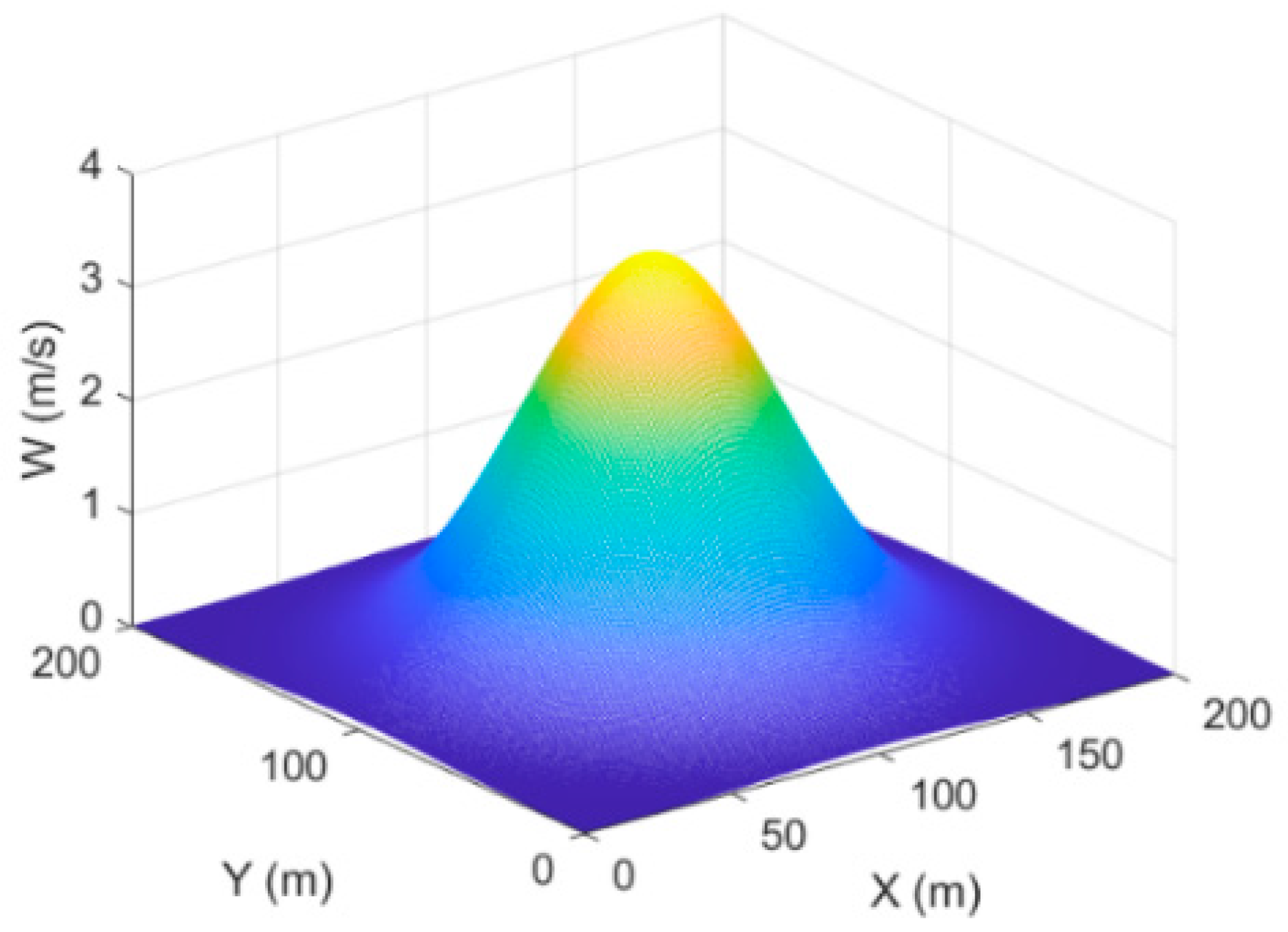
2.1. Model of Thermal

A soaring UAV is able to extract energy from the thermal updraft. It is a Gaussian distribution based on thermal radius and strength. The Gaussian model defines the vertical wind, with the vertical velocity as a function of distance from the thermal center [11]:
w t h = W max e ( x x t h ) 2 + ( y y t h ) 2 R 2
where xth and yth are the center of the thermal, Wmax and R are the maximum intensity and radius of the thermal, respectively, and wth is the vertical velocity of the SUAV during soaring. Figure 1 presents an example of a thermal updraft model whose Wmax is 3.5 m/s and R is 50 m.

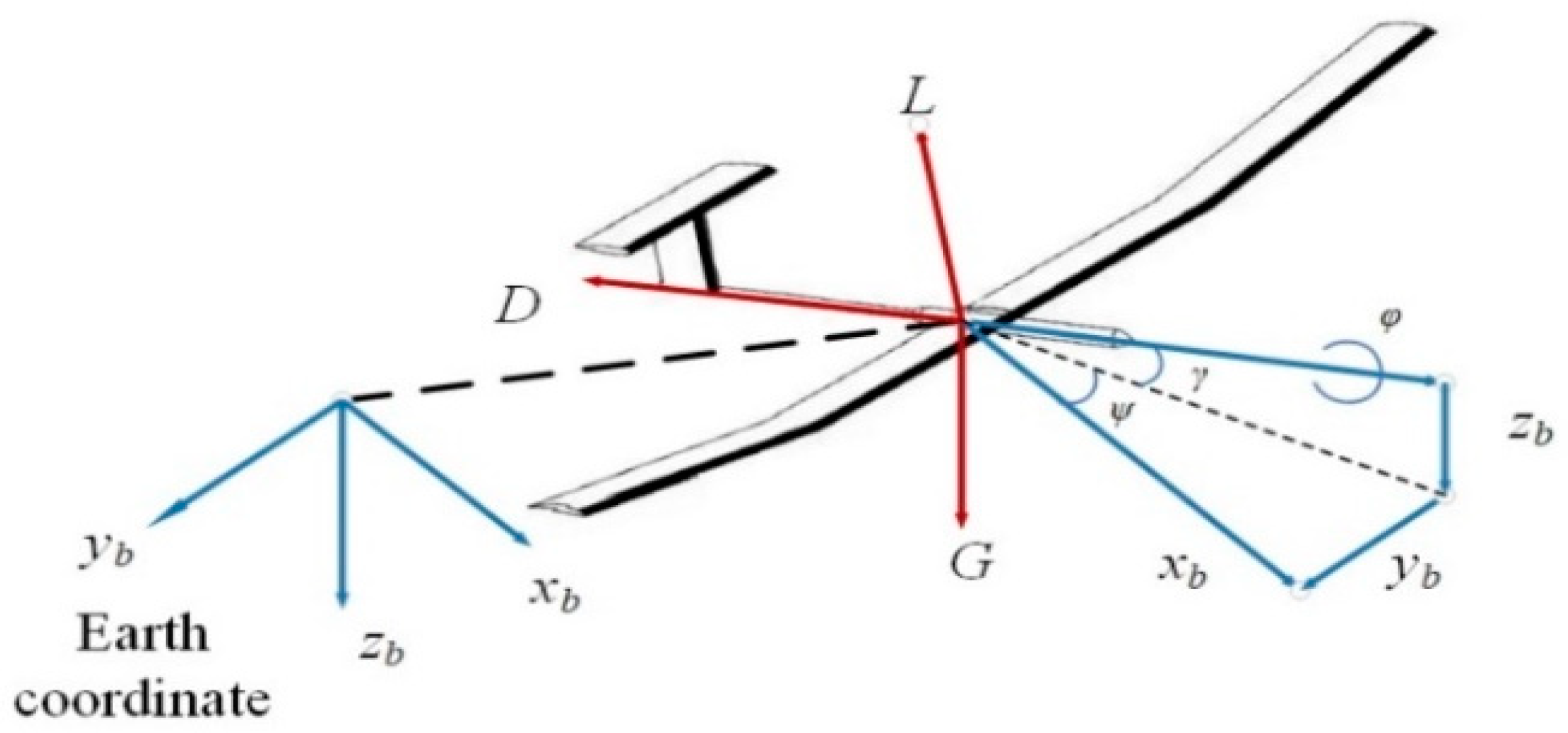
2.2. Vehicle Kinematic Model

To soar with the thermal updraft, a simplified SUAV dynamic model is employed for simulation purposes. The pitch rate is more complicated in the soaring process, and the aim of this work is to analyze the electric energy variation in the SUAV through thermal. For this reason, the control outputs u1 and u2 can be assumed to be controlled automatically by autopilot and ignored in the model, especially in the soaring process. In addition, assuming gravity and lift are equal, the SUAV velocity maintains a constant value in the flight. Based on ref. [29] and the assumptions above, we establish a five-degree-of-freedom (DOF) dynamic model:
{ x ˙ = V cos ψ cos γ y ˙ = V sin ψ cos γ z ˙ = V sin γ + w t h γ ˙ = L cos ϕ     m g cos γ m V ψ ˙ = L sin ϕ m V cos γ
where x, y are the position of the SUAV; z is the altitude; V is the speed; g is the gravitational acceleration; CL is the lift coefficient; and ψ, γ, ϕ are the heading angle, flight path angle and bank angle, respectively (see Figure 2). In this work, the thrust is zero during the gliding phase, and the flight path angle can be calculated in Section 4 depending on the force balance analysis of the drag and weight of the SUAV.

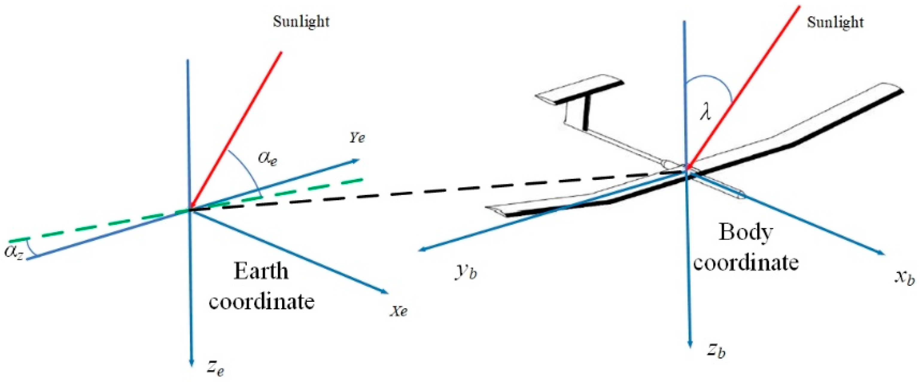
2.3. Solar Irradiance Model

The SUAV can acquire energy from sunlight and convert it into electric energy through the solar panel. The solar radiation can be computed according to the following steps. First, we compute the solar irradiance I (W/m2), which is perpendicular to the horizontal solar panel on the wing [30]:
I = I 0 ( 1 + 0.034 cos 2 π n d a y 365.25 )
where I0 is the solar constant, and nday is the number of days starting from January 1st in a year.
The absorbed and diffused solar irradiation from sunlight by the SUAV are affected by atmospheric conditions and air mass. A series of empirical functions can approximate the solar energy losses. According to Hottel [31], the beam radiation Ib can be given including the solar zenith angle and altitude for four climates as follows [32]:
I b = I τ b
where τb is the direct atmospheric transmittance expressed as:
τ b = r 0 a 0 + r 1 a 1 e ( r k k / cos ( α z ) )
where r0, r1 and rk are correction factors under different climate types and seasons. The corresponding values are r0 = 1.03, r1 = 1.01 and rk = 1 in midlatitude winter [32]. a0, a1 and ak are the constants associated with altitude, which can be calculated as follows [31]:
{ a 0 = 0.4237 0.00821 ( 6 z ) 2 a 1 = 0.5055 0.00595 ( 6.5 z ) 2 k = 0.2711 + 0.01858 ( 2.5 z ) 2
Similar to Equation (4), the diffuse radiation Id is:
I d = I τ d
where the diffuse atmospheric transmittance τd can be obtained from the following empirical expression [31]:
τ d = 0.271 0.294 * τ b
The solar altitude angle αe and solar azimuth angle αz are variables under different solar times and latitudes with the following expression [30]:
sin α e = sin n l a t sin δ + cos n l a t cos δ cos ω ( t ) sin α z = cos δ cos ω ( t ) cos α e δ = 0.4093 sin ( 2 π ( 284 + n d a y ) 365 ) ω ( t ) = 0.2618 ( 12 t l o c a l )
where nlat is the latitude, δ is the declination angle of the sun, ω(t) is the hour of the sun, and tlocal is the current time of the day.
Next, the solar incident angle on the surface of the wing is calculated in order to obtain the solar irradiance on the wing of the SUAV. It describes the angle between the sunlight and the solar panel on the airfoil of the SUAV. An earth coordinate frame and a body-fixed coordinate frame are built (see Figure 3), in which E, N, D point to the orientations of east, north and ground, respectively. We define the unit vector of the sunlight Vp under the earth coordinate frame:
V p = [ cos α e cos α z cos α e sin α z sin α e ]
In the body-fixed coordinate frame, the unit vector Vb along the reverse direction of the axis Obzb towards the ground can be expressed as:
V b = [ 0 0 1 ] T
Then, the vector Vp can be converted into the vector Vpb according to the principle of rotating coordinate transformation, which yields:
V p b = L x ( ϕ ) L y ( γ ) L z ( ψ ) [ cos α e cos α z cos α e sin α z sin α e ]
where Lx, Ly, Lz are the element rotation matrices. The flight path angle (or the pitch angle) is ignored in the function because it is small (less than 5 degrees) in the gliding and soaring phase.
According to Equations (5)–(8) above, the incident angle λ is achieved:
cos λ = cos α e sin α z cos ψ sin ϕ cos α e cos α z sin ψ sin ϕ + sin α e cos ϕ

2.4. Energy Model of the SUAV

If the incident angle and the attitude of the SUAV are known, the power generation can be calculated. The SUAV electric power input is expressed as [30]:
P b = { cos λ I b   if   cos λ 0 0 if   cos λ < 0 P d = I d cos 2 ϕ 2 P i n = ( P b + P d ) η s o l a r S s o l a r
where Pb, Pd are the beam irradiance and the diffuse irradiance. In addition, Ssolar is the area of the solar panel, and ηsolar is the conversion efficiency of the solar cell.
We assume the lift and gravity of the SUAV are in balance during the whole flight. According to this assumption, the SUAV power output is calculated as [30]:
{ P o u t = T V η p r o p T = D = 1 2 ρ V 2 S C D C D = C D 0 + C L 2 ε π R a C L = 2 m g ρ V 2 S cos ϕ
where T is the thrust, ηprop is the propeller efficiency, D is the drag force, ρ is the air density, S is the area of the wing, CD is the drag coefficient, CD0 is the parasitic drag coefficient, ε is the Oswald efficiency factor, Ra is the aspect ratio of the wing, CL is the lift coefficient, m is the mass, and g is the gravity.
Hence, the energy generation Ein, consumed energy Eout and stored electric energy Etotal are obtained:
E i n ( t 0 , t f ) = t 0 t f P i n d t E o u t ( t 0 , t f ) = t 0 t f P o u t d t
E t o t a l = E i n E o u t

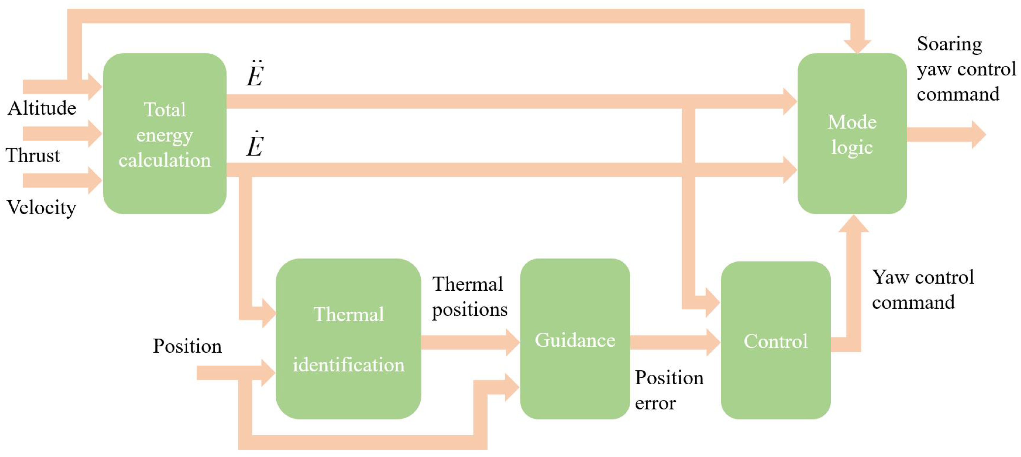
3. Integrated Guidance and Control Process for Soaring

3.1. Total Energy and Autonomous Soaring Process

Thermal center estimation plays a significant role in soaring, since the SUAV raises its altitude by circling the estimated center. However, no onboard sensor can measure the actual vertical airspeed in practice. Therefore, it is necessary to predict the thermal location and vertical velocity through limited parameters for the SUAV during flight. The concept of total energy concerning the potential and kinetic of the SUAV is developed to assist in estimating the thermal center location. The normalized total energy E and energy rate E ˙ are defined as follows:
E = h + V 2 2 g
E ˙ = h ˙ + V V ˙ g
where h is the altitude, which is the same as z in the function. Finally, the energy acceleration E ¨ is obtained after differentiation.
Figure 4 shows the whole structure and process for autonomous soaring once the SUAV flies closer to the updraft. The input in the system is the velocity, thrust, altitude and position of the SUAV. To begin with, the energy rate and its derivative are obtained. The goal of the estimator is to predict the location of the thermal center using the measurement from the energy variometer with the data from the SUAV’s sensor or state. In this work, the soaring radius is set to 30 m based on the SUAV’s minimum turn rate radius. The guidance and control block are used to calculate the turn rate command to guide the SUAV to circle the thermal center. Finally, the mode logic block is used to determine whether the SUAV needs to switch to the soaring mode or if it will fail, depending on the value of the altitude.
In the thermal identification block, the historical flight data of the SUAV’s position and energy rate E ˙ are stored in a n*3 matrix:
[ P x 1 P y 1 E ˙ 1 P x 2 P y 2 E ˙ 2 P x n P y 1 E ˙ n ]
where the subscript n denotes the nth recorded historical data. The vertical velocity of the SUAV close to a thermal is approximately equal to the average of the E ˙ column.
Then, the thermal center can be estimated in different manners such as the weighted average, the Gaussian regression and the Kalman filter. Referring to Allen, this work utilizes the weighted average to estimate the thermal location. The estimation function corresponds to the “Thermal identification” block in Figure 4 and calculates the output for guidance and control.

3.2. Guidance and Control

Finally, a guidance law, a feedback controller and a mode logic (see Equations (17)–(20)) are established similar to ref. [14] to lead the SUAV in soaring around the center of the thermal when predicting the updraft location. The SUAV will switch to the soaring mode if the E ˙ is above 0.3 m/s, and the thermal is left out once it has climbed 100 m.
S = ( x x ^ t h ) 2 + ( y y ^ t h ) 2
ψ s o a r = V r
e p = r S
ψ ˙ = k 1 E ¨ s + k 2 e p + k 3 e ˙ p + ψ s o a r
where S is the distance between the SUAV and the predicted thermal center, r and ψsoar are the radius and heading angle during soaring, ep is the difference between r and S, and E ˙ is the required feedback control when the SUAV soars in the thermal. The simulation result for using different thermals to achieve soaring is presented in Section 5.

4. Simulation and Results

This section provides a series of numerical simulations to investigate the effect of different factors (e.g., solar radiation, strength or velocity) on energy variation for SUAVs during soaring. In this work, we consider the scenario in Beijing (39.93° N, 116.28° E) at 16:00 on March 1st. The initial position of the SUAV and the thermal are (0, 0) and (200, 200), respectively. The strength of the thermal is 2.5 m/s, and the radius is 50 m. We assume that the SUAV maintains a constant velocity of 10 m/s during the flight process. To eliminate the influence of different altitudes on soaring and gliding time, the soaring height is limited to 100 m. The initial altitude of the SUAV is 500 m, and the altitude limit is about 600 m. The other parameters regarding the SUAV are referred to in ref. [28] and are listed in Table 1.
The motion of the SUAV includes the cruise phase, gliding phase and soaring phase. In this paper, the thrust is zero when the SUAV glides, and the flight path angle is set to −4.3 degrees according to the force balance analysis of the drag and weight of the SUAV (V = 10 m/s). The flight path angle of the SUAV under different velocities during the gliding phase is presented in Table 2.

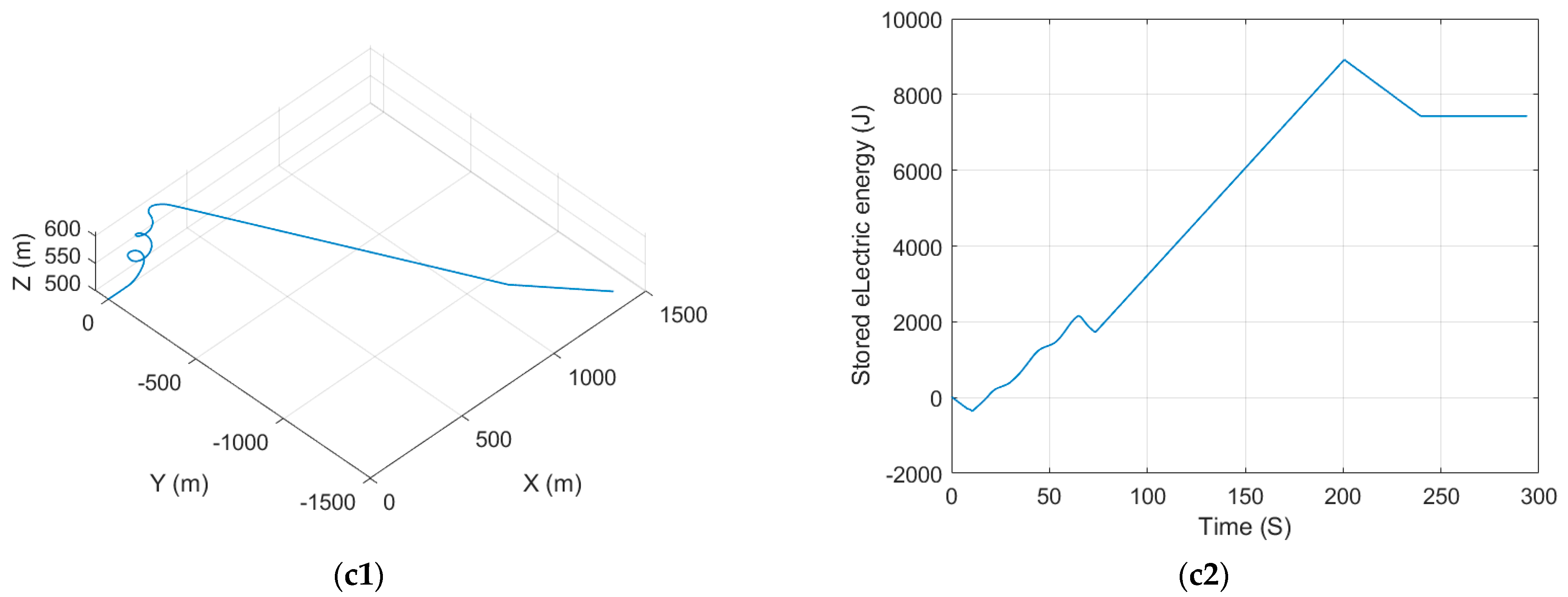
4.1. Stored Electric Energy Analysis

Figure 5 shows a typical trajectory of the SUAV with the thermal. At first, the SUAV cruises at a specific altitude of 500 m. It turns to soar around the thermal center when it flies close to the updraft. Once the SUAV climbs about 100 m, it leaves the thermal and starts to glide until descending to 500 m.
We can also conclude from Figure 5 that the gliding time and the soaring time are relatively close for SUAVs, even though the gliding distance is much longer than the soaring height in the 3D space. This means the SUAV can acquire enough energy from both the gliding and soaring processes under this condition.
According to Equations (3)–(5), for different dates or times, different solar radiation will appear, which leads to diverse solar power generation for solar cells. Figure 6 shows the SUAV’s electric energy input and storage profile under different dates and local times. During soaring and gliding, it is apparent that the electric generation would be affected by solar irradiation. For example, the value of solar energy generation at 12:00 is three times that of 16:00, and it is four times that of stored electric energy. The battery of the SUAV could be charged in the two phases, and stronger solar irradiation allows the SUAV to gain more energy benefits from thermals.
Figure 7 shows the energy storage in SUAVs with or without soaring at different velocities. The stored electric energy of the SUAV can be increased to 2.75 × 10⁴ J through thermal at the velocity of 13 m/s, whereas the value is 1.75 × 10⁴ J if the velocity is 10 m/s. The endurance of SUAVs can be extremely improved by soaring with thermal. In doing so, the SUAV’s energy will benefit from soaring if the energy consumption is greater. SUAVs maintain a very small thrust consumption during the soaring and gliding phases (see Figure 8) regardless of the velocity. By contrast, different velocities have a great impact on the SUAV’s energy consumption during the cruise phase.
Figure 8 shows the input, output and charge (or discharge) power profiles for SUAVs with thermal at different velocities and local times. The SUAV’s velocity has a small influence on the power output during the soaring and gliding phases due to the fact that both phases produce a smaller electric power output. For this reason, and in conjunction with the conclusion in Figure 6, solar radiation, instead of velocity, plays the leading role in the charge power of the SUAV during soaring and gliding.
Figure 9 presents the electric energy storage profile at different SUAV velocities and thermal strengths. Based on the force balance of the drag and weight of the SUAV, at different velocities, the SUAV will generate different flight path angles during gliding. The corresponding flight path angle is calculated as 4.5 degrees (V = 11 m/s), 4.8 degrees (V = 12 m/s) and 5.1 degrees (V = 11 m/s), respectively. With the different flight path angles, a faster velocity results in a shorter gliding time, and less strength leads to a rise in soaring time in the thermal.
Figure 9a shows that a lower velocity of the SUAV brings on an extra 50 s gliding time. The velocity of 10 m/s produces an additional 2700 J electric energy than that the velocity of 13 m/s.
Figure 10 presents the SUAV’s altitude profile through thermal at different thermal strengths (a) and velocities (b). The difference in soaring time for the SUAV may reach 50 s at different thermal strengths, and the gliding time at V = 10 might be nearly 40 s longer than that at V = 13 m/s. Theoretically, more soaring and gliding time brings about more charging time for the SUAV, but the amount of electric energy storage is determined by power and time. For this reason, a longer soaring and gliding time are conducive for energy harvesting for the SUAV at the same power input, meeting the results in conjunction with Figure 9a and Figure 10b. Nevertheless, the velocity determines the flight path angle, which affects the gliding time. Thus, a slower velocity would produce more gliding time to increase the electric energy gains. Combined with Figure 6, Figure 9 and Figure 10, the electric energy variation is primarily influenced by solar irradiation, which has the most significant impact. Following this, the thermal strength also contributes to the variation, and the energy is less affected by the SUAV’s velocity.

4.2. Equivalent Endurance

The stored electric energy increases during the soaring and gliding processes, whereas it gradually decreases when the SUAV switches to cruise mode. Figure 11 shows the electric energy profile of the SUAV during the soaring, gliding and cruise phases with one thermal. It is clear that the SUAV’s stored electric energy under 10 m/s decreases to zero at 537 s, and the corresponding values under diverse SUAV velocities are different.
The total time remaining minus the time spent soaring and gliding is approximately equal to the additional endurance time that the SUAV obtains from the thermal. This time can be regarded as the equivalent endurance time, and the corresponding distance is the equivalent endurance distance. The equivalent endurance varies with the SUAV’s velocity (or power consumption). The SUAV can determine whether it is supposed to operate with thermal in order to soar based on the proposed equivalent endurance when it flies toward the destination. The SUAV would spend excessive energy to reach the thermal if the updraft is too far away from the SUAV or the destination.

4.3. SUAV Velocity Selection and Energy Variation under Time Constraints

According to Figure 8 and the energy model of Equation (15), a slower velocity will lead to a decrease in the electric power. However, the SUAV needs to consider time constraints and minimum velocity when performing its tasks. This condition is discussed in this work. The end of the mission is assumed to be set (1410, 1410) for simplification. Table 3 presents the SUAV’s energy optimal velocity under different time constraints and thermal strengths.
Figure 12 presents the flight trajectory and electric energy profiles under different thermal strengths and time constraints. The SUAV’s velocity in each condition is calculated based on the time constraint for the maximum electric energy. Comparing Figure 12(a1,a2) with Figure 12(b1,b2), it can be concluded that for the same thermal strength, a shorter time constraint will cause the SUAV to reach its destination at a faster speed and spend more and more energy. Furthermore, comparing Figure 12(a1,a2) with Figure 12(c1,c2) shows that slower thermal strengths will lead to faster SUAV velocity under the same time constraints. That is because a slower thermal strength leads to an increase in soaring time, which in turn shortens the gliding and soaring time costs.
In summary, the time cost for a SUAV to reach its destination through thermal consists of two components. The soaring time depends on the thermal strength, and the gliding and cruising time is determined by the SUAV’s velocity. In the case of mission time constraints, the SUAV will choose different velocities to ensure that the energy is maximized while reaching the destination.

5. Conclusions

This work aims to discuss the electric energy performance of a SUAV soaring through thermal under different conditions. It provides a detailed analysis of the impact of thermal strength, solar irradiation and velocity on variations in electric energy, which has not been explored before. Several compelling conclusions can be drawn from the simulation results.
(1)
The SUAV has advanced endurance with thermal, with a more pronounced effect observed when the SUAV’s thrust consumption is higher.
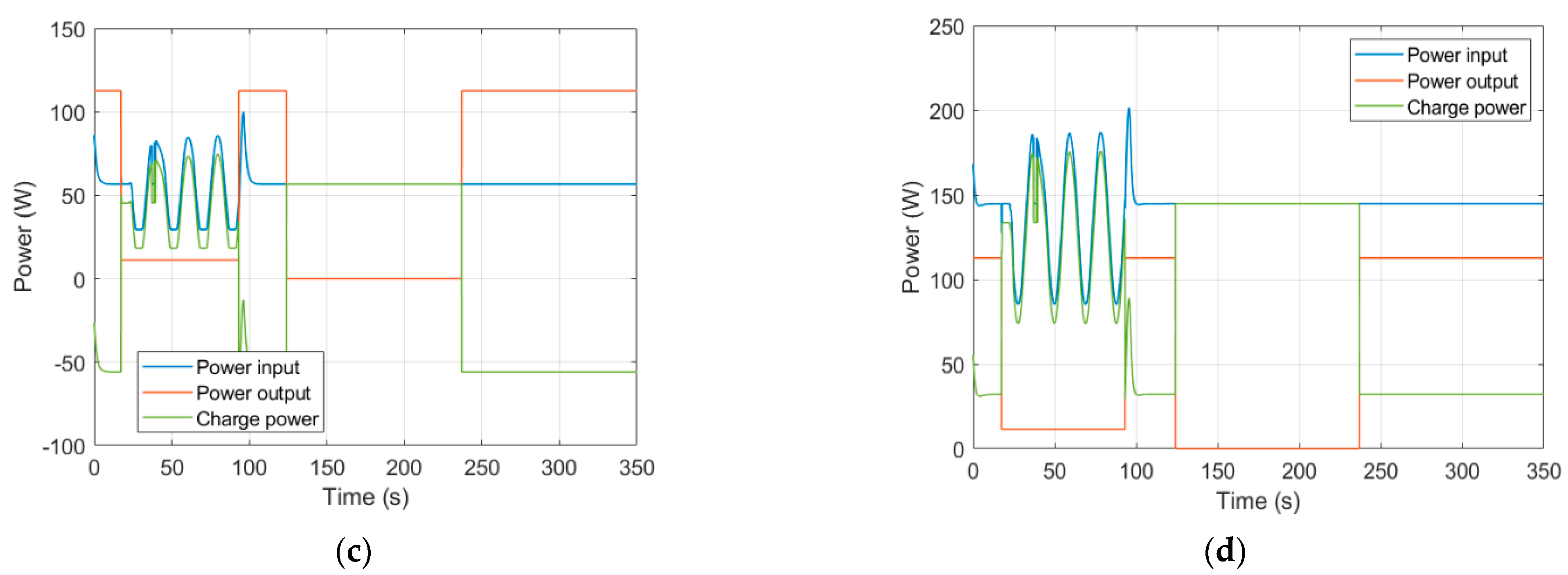
(2)
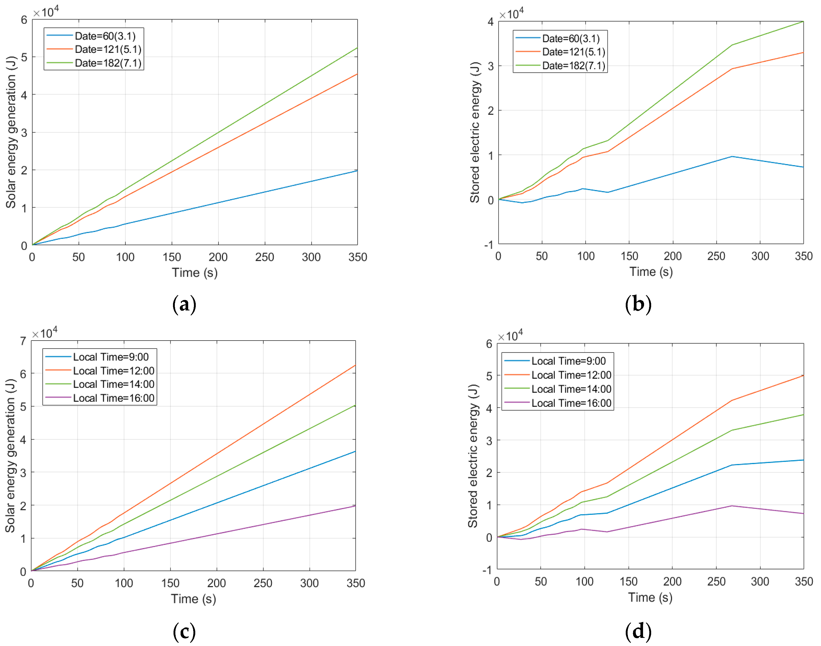
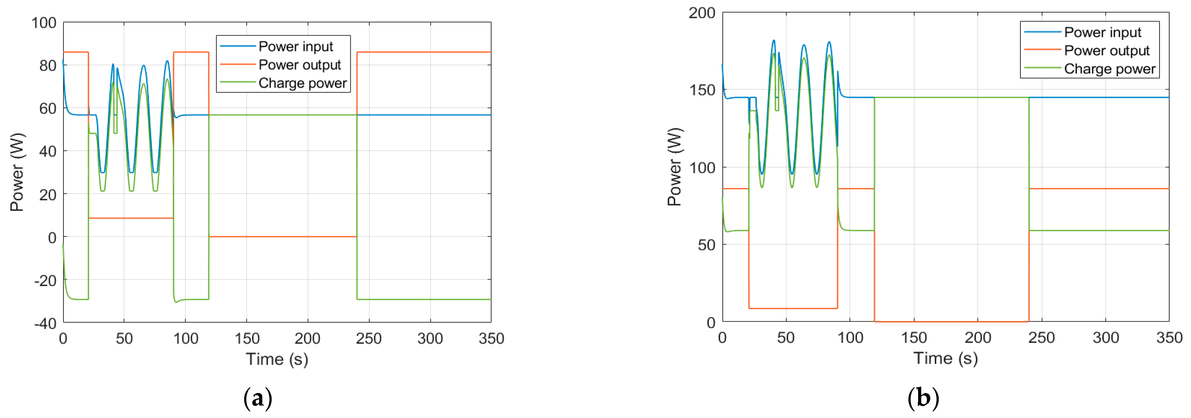
The charging power of the SUAV is mainly determined by solar irradiation during soaring and gliding, whereas the influence of velocity and power consumption is not as crucial as previously presumed. This is because the thrust remains at a low level during the soaring or gliding phase.
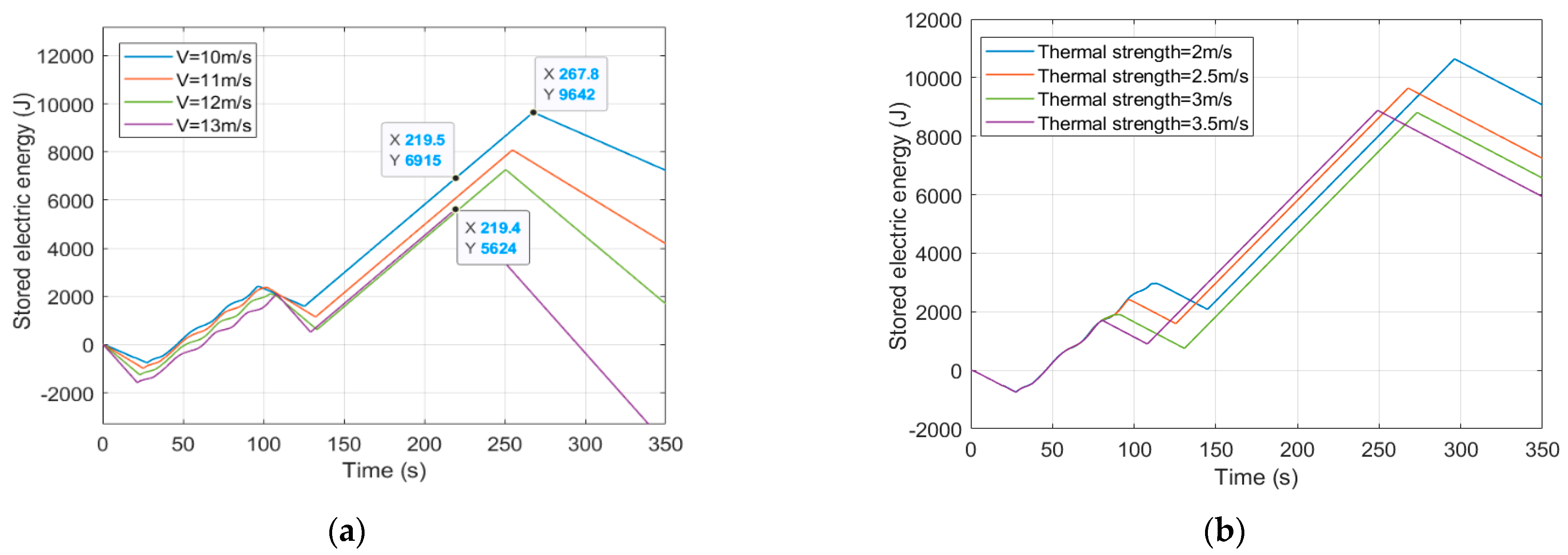
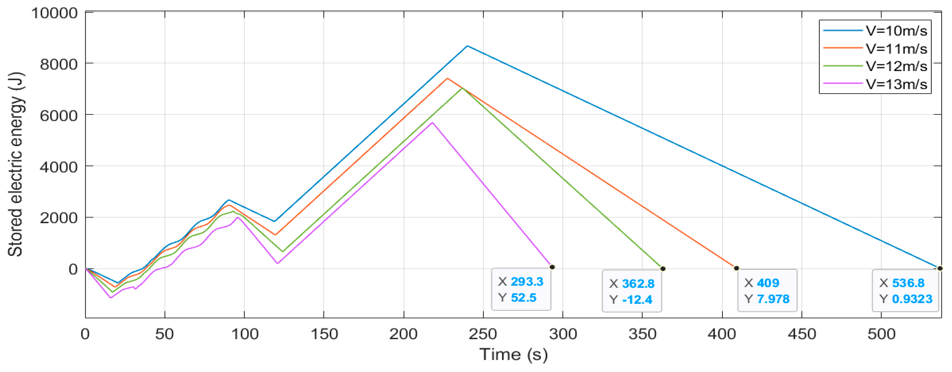
(3)
Both power and time play significant roles in the electric energy harvested from thermals. Velocity and thermal strength independently affect the gliding and soaring time, thereby influencing the electric energy storage at the same power.
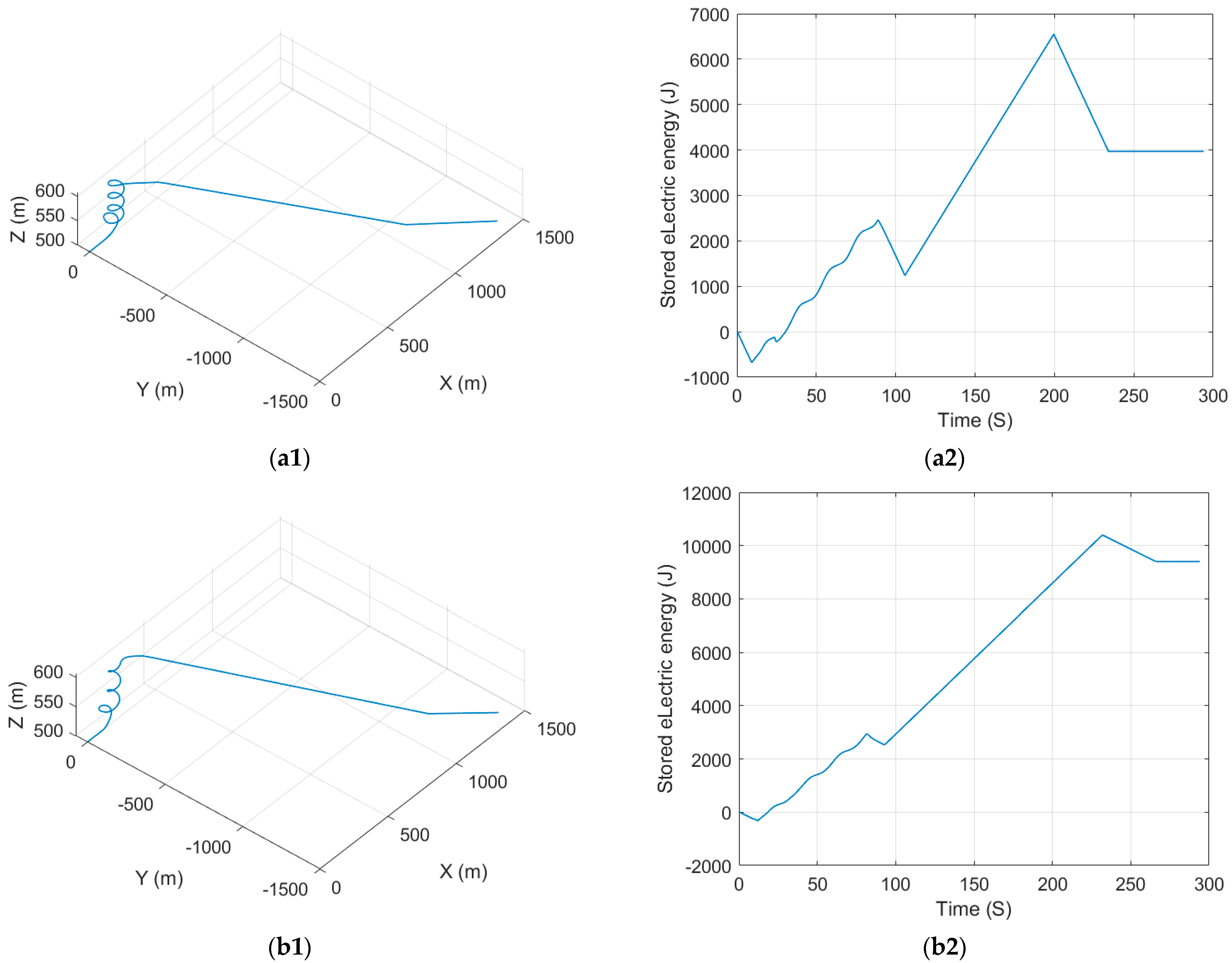
(4)
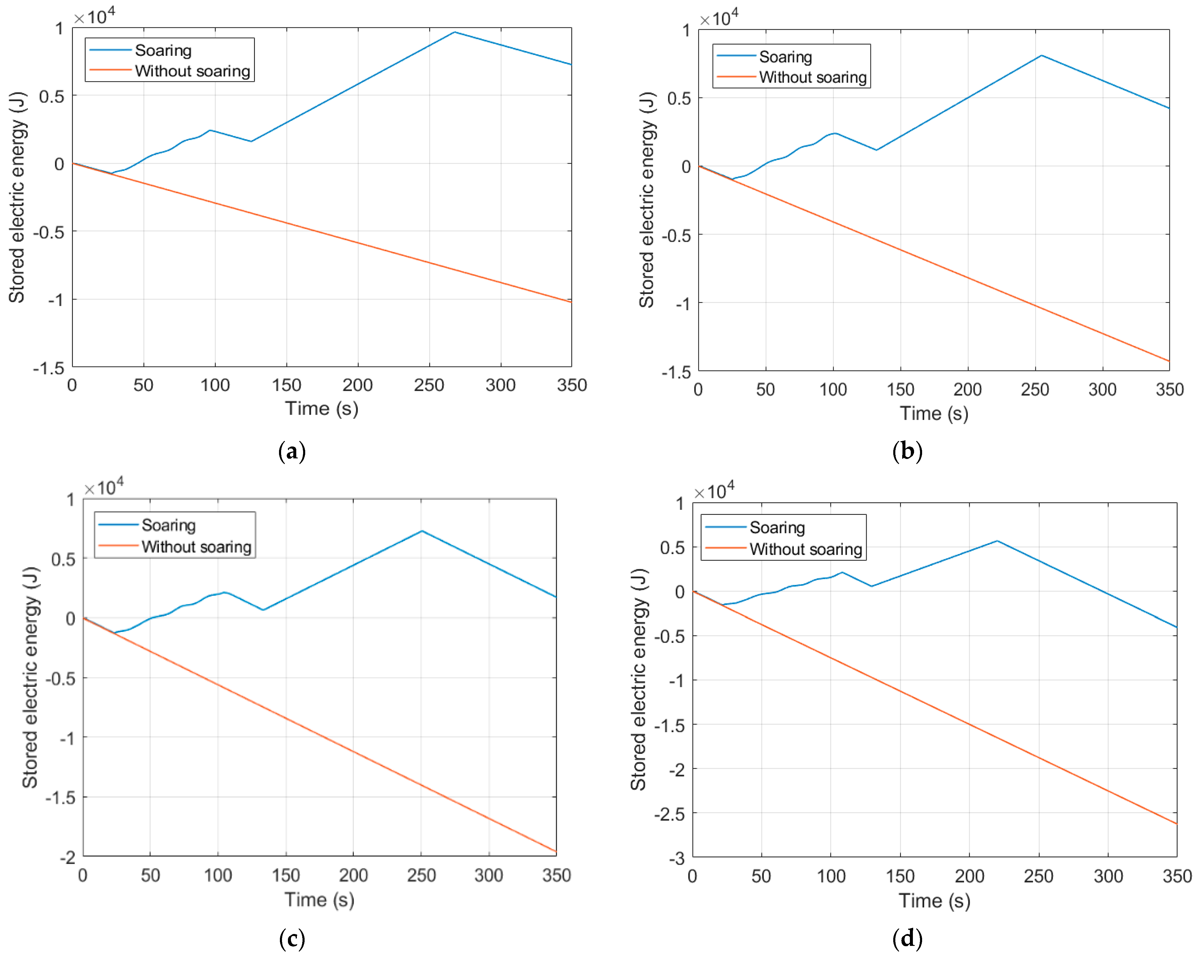
The concept of equivalent endurance is put forward to evaluate the extra energy that the SUAV harvests from a thermal compared to a direct flight condition.
(5)
The time constraint is considered to obtain the most appropriate velocity for the SUAV by soaring to meet possible mission conditions. The SUAV’s chosen velocity is influenced by the limited time and thermal strength.
These conclusions have essential insights for improvements in SUAV endurance with soaring through thermals. Furthermore, the mission time constraint will be taken into account to establish a multi-objective optimization problem to be researched in a further work.

Author Contributions

Conceptualization, Y.W. and K.L.; methodology, Y.W., K.L. and H.L.; software, Y.W. and Y.L.; validation, Y.W., A.Z. and H.L.; formal analysis, Y.W., A.Z. and Y.L.; investigation, Y.W. and H.L.; resources, K.L. and D.W.; data curation, Y.W., A.Z. and Y.L.; writing—original draft preparation, Y.W., A.Z., H.L. and Y.L; writing—review and editing, K.L. and D.W.; visualization, Y.W.; supervision, K.L. and D.W.; project administration, K.L.; funding acquisition, K.L. All authors have read and agreed to the published version of the manuscript.

Funding

This work is supported by the Chinese National Natural Science Foundation (No. 61773039) and the Aeronautical Science Foundation of China (No. 2017 × 51018).

Institutional Review Board Statement

Not applicable.

Informed Consent Statement

Not applicable.

Data Availability Statement

Not applicable.

Conflicts of Interest

The authors declare no conflict of interest.

References

  1. Gao, X.Z.; Hou, Z.X.; Guo, Z.; Chen, X.Q. Reviews of methods to extract and store energy for solar-powered aircraft. Renew. Sustain. Energy Rev. 2015, 44, 96–108. [Google Scholar] [CrossRef]
  2. Hu, S.Y.; Ni, W.; Wang, X.; Jamalipour, A. Disguised Tailing and Video Surveillance with Solar-Powered Fixed-Wing Unmanned Aerial Vehicle. IEEE Trans. Veh. Technol. 2022, 71, 5507–5518. [Google Scholar] [CrossRef]
  3. Huang, H.L.; Savkin, A.V. Energy-efficient decentralized navigation of a team of solar-powered UAVs for collaborative eavesdropping on a mobile ground target in urban environments. Ad Hoc Netw. 2021, 117, 102485. [Google Scholar] [CrossRef]
  4. Lun, Y.B.; Yao, P.; Wang, Y.X. Trajectory Optimization of SUAV for Marine Vessels Communication Relay Mission. IEEE Syst. J. 2020, 14, 5014–5024. [Google Scholar] [CrossRef]
  5. Li, K.; Wu, Y.; Bakar, A.; Wang, S.; Li, Y.; Wen, D. Energy System Optimization and Simulation for Low-Altitude Solar-Powered Unmanned Aerial Vehicles. Aerospace 2022, 9, 331. [Google Scholar] [CrossRef]
  6. Allen, M. Updraft Model for Development of Autonomous Soaring Uninhabited Air Vehicles. In Proceedings of the 44th AIAA Aerospace Sciences Meeting and Exhibit, Reno, NV, USA, 6–12 January 2006. [Google Scholar]
  7. Kahveci, N.E.; Ioannou, P.A.; Mirmirani, M.D. Adaptive LQ Control with Anti-Windup Augmentation to Optimize UAV Performance in Autonomous Soaring Applications. IEEE Trans. Control Syst. Technol. 2018, 16, 691–707. [Google Scholar] [CrossRef]
  8. Walton, C.; Kaminer, I. Alternate Strategies for Optimal Unmanned Aerial Vehicle Thermaling. J. Aircr. 2018, 55, 2347–2356. [Google Scholar] [CrossRef]
  9. Allen, M.; Lin, V.; Samuel, T. Guidance and Control of an Autonomous Soaring Vehicle with Flight Test Results. In Proceedings of the 45th AIAA Aerospace Sciences Meeting and Exhibit, Reno, NV, USA, 8–11 January 2007. [Google Scholar]
  10. Tabor, S.; Guilliard, I.; Kolobov, A. ArduSoar: An Open-Source Thermalling Controller for Resource-Constrained Autopilots. In Proceedings of the 25th IEEE/RSJ International Conference on Intelligent Robots and Systems, Madrid, Spain, 1–5 October 2018. [Google Scholar]
  11. Kahn, A.D. Atmospheric Thermal Location Estimation. J. Guid. Control Dyn. 2017, 40, 2359–2365. [Google Scholar] [CrossRef]
  12. Notter, S.; Gross, P.; Schrapel, P. Fichte, Multiple Thermal Updraft Estimation and Observability Analysis. J. Guid. Control Dyn. 2020, 43, 490–503. [Google Scholar] [CrossRef]
  13. Chung, J.J.; Lawrance, N.R.J.; Sukkarieh, S. Learning to soar: Resource-constrained exploration in reinforcement learning. Int. J. Robot. Res. 2015, 34, 158–172. [Google Scholar] [CrossRef]
  14. Notter, S.; Schimpf, F.; Muller, G.; Fichter, W. Hierarchical Reinforcement Learning Approach for Autonomous Cross-Country Soaring. J. Guid. Control Dyn. 2022, 46, 114–126. [Google Scholar] [CrossRef]
  15. Schermann, E.; Omran, H.; Durand, S.; Kiefer, R. Stochastic Trajectory Optimization for Autonomous Soaring of UAV. In Proceedings of the 11th International-Federation-of-Automatic-Control (IFAC) Symposium on Nonlinear Control Systems, Vienna, Austria, 4–6 September 2019. [Google Scholar]
  16. Gunetti, P.; Thompson, H.; Dodd, T. Autonomous mission management for UAVs using soar intelligent agents. Int. J. Syst. Sci. 2013, 44, 831–852. [Google Scholar] [CrossRef]
  17. Cobano, J.A.; Alejo, D.; Vera, S.; Heredia, G.; Ollero, A. Multiple gliding UAV coordination for static soaring in real time applications. In Proceedings of the 2013 IEEE International Conference on Robotics and Automation, Karlsruhe, Germany, 6–10 May 2013. [Google Scholar]
  18. Andersson, K.; Jones, K.; Dobrokhodov, V.; Kaminer, I. Thermal Highs and Pitfall Lows -Notes on the Journey to the First Cooperative Autonomous Soaring Flight. In Proceedings of the 51st IEEE Annual Conference on Decision and Control, Maui, HI, USA, 10–13 December 2012. [Google Scholar]
  19. Mateja, K.; Skarka, W.; Peciak, M.; Niestrój, R.; Gude, M. Energy Autonomy Simulation Model of Solar Powered UAV. Aerospace 2023, 10, 479. [Google Scholar] [CrossRef]
  20. Peciak, M.; Skarka, W.; Mateja, K.; Gude, M. Impact Analysis of Solar Cells on Vertical Take-Off and Landing (VTOL) Fixed-Wing UAV. Energies 2023, 16, 247. [Google Scholar] [CrossRef]
  21. Huang, Y.; Chen, J.G.; Wang, H.L.; Su, G.F. A method of 3D path planning for solar-powered UAV with fixed target and solar tracking. Aerosp. Sci. Technol. 2019, 92, 831–838. [Google Scholar] [CrossRef]
  22. Wu, J.F.; Wang, H.L.; Huang, Y.; Zhang, M.H.; Su, Z.K. Solar-Powered Aircraft Endurance Map. J. Guid. Control Dyn. 2019, 42, 687–694. [Google Scholar] [CrossRef]
  23. Edwards, D.J.; Kahn, A.D.; Kelly, M.; Heinzen, S.; Scheiman, D.A.; Jenkins, P.P.; Walters, R.; Hoheisel, R. Maximizing net power in circular turns for solar and autonomous soaring aircraft. J. Aircr. 2016, 53, 1237–1247. [Google Scholar] [CrossRef]
  24. Huang, Y.; Wang, H.L.; Yao, P. Energy-optimal path planning for Solar-powered UAV with tracking moving ground target. Aerosp. Sci. Technol. 2016, 53, 241–251. [Google Scholar] [CrossRef]
  25. Wu, J.; Wang, H.; Li, N.; Yao, P.; Huang, Y.; Su, Z.; Yu, Y. Distributed trajectory optimization for multiple solar-powered UAVs target tracking in urban environment by Adaptive Grasshopper Optimization Algorithm. Aerosp. Sci. Technol. 2017, 70, 497–510. [Google Scholar] [CrossRef]
  26. Wu, J.F.; Wang, H.L.; Li, N.; Yao, P.; Huang, Y.; Yang, H.M. Path planning for solar-powered UAV in urban environment. Neurocomputing 2018, 275, 2055–2065. [Google Scholar] [CrossRef]
  27. Kim, S.H.; Padilla, G.E.G.; Kim, K.J.; Yu, K.H. Flight Path Planning for a Solar Powered UAV in Wind Fields Using Direct Collocation. IEEE Trans. Aerosp. Electron. Syst. 2020, 56, 1094–1105. [Google Scholar] [CrossRef]
  28. Oettershagen, P.; Stastny, T.; Hinzmann, T.; Rudin, K.; Mantel, T.; Melzer, A.; Wawrzacz, B.; Hitz, G.; Siegwart, R. Robotic technologies for solar-powered UAVs: Fully autonomous updraft-aware aerial sensing for multiday search-and-rescue missions. J. Field Robot. 2018, 35, 612–640. [Google Scholar] [CrossRef]
  29. Walton, C.; Kaminer, I.; Dobrokhodov, V.; Jones, K.D. New Insights into Autonomous Soaring. In Proceedings of the 2017 IEEE 56th Annual Conference on Decision and Control, Melbourne, Australia, 12–15 December 2017. [Google Scholar]
  30. Xin, W.; Yao, P.; Xie, Z. Comprehensive optimization of energy storage and standoff tracking for solar-powered UAV. IEEE Syst. J. 2020, 14, 5133–5143. [Google Scholar]
  31. Hottel, H.C. A simple model for estimating the transmittance of direct solar radiation through clear atmospheres. Sol. Energy 1976, 18, 129–134. [Google Scholar] [CrossRef]
  32. Duffie, J.A.; Beckman, W.A. Solar Engineering of Thermal Processes, 4th ed.; John Wiley & Sons, Inc.: Hoboken, NJ, USA, 2013. [Google Scholar]
Figure 1. Thermal updraft model for Wmax = 3.5 m/s, R = 50 m.
Aerospace 10 00779 g001
Figure 2. Forces and Euler angles for the SUAV.
Aerospace 10 00779 g002
Figure 3. Solar incidence angle on the SUAV.
Aerospace 10 00779 g003
Figure 4. Autonomous soaring guidance and control process.
Aerospace 10 00779 g004
Figure 5. The SUAV trajectory for soaring and gliding process: (a) 3D space, (b) xy plane, (c) z plane (altitude).
Aerospace 10 00779 g005
Figure 6. SUAV energy variation through thermal under V = 10 m/s: (a) solar energy generation at 16:00 on different dates, (b) stored electric energy at 16:00 on different dates, (c) solar energy generation on May 1st at different local times, (d) stored electric energy on May 1st at different local times.
Aerospace 10 00779 g006
Figure 7. The SUAV’s stored electric energy with or without soaring under different velocities at 16:00 on May 1st: (a) V = 10 m/s, (b) V = 11 m/s, (c) V = 12 m/s, (d) V = 13 m/s.
Aerospace 10 00779 g007
Figure 8. The SUAV input, output and charge power under different velocities and at different local times on May 1st: (a) V = 10 m/s, local time = 16:00; (b) V = 10 m/s, local time = 14:00; (c) V = 12 m/s, local time = 16:00; (d) V = 12 m/s, local time = 14:00.
Aerospace 10 00779 g008aAerospace 10 00779 g008b
Figure 9. The SUAV’s stored electric energy profile at 16:00 on May 1st under different (a) velocities and (b) strengths.
Aerospace 10 00779 g009
Figure 10. The SUAV altitude profile under different strengths (a) and velocities (b).
Aerospace 10 00779 g010
Figure 11. The SUAV’s electric energy storage under different velocities.
Aerospace 10 00779 g011
Figure 12. SUAV flight trajectory and electric energy: (a1,a2) time constraint 230 s, V = 13 m/s, thermal strength = 2.5 m/s; (b1,b2) time constraint 260 s, V = 10 m/s, thermal strength = 2.5 m/s; (c1,c2) time constraint 230 s, V = 10.8 m/s, thermal strength = 3.5 m/s.
Aerospace 10 00779 g012aAerospace 10 00779 g012b
Table 1. Parameters of the SUAV.
SignTitle 2ValueUnit
I0Solar irradiance1367W/m2
τbBeam optical depths0.626N/A
τdDiffuse optical depths1.707N/A
SsolarSolar cell area1.37m2
SWing area1.75m2
mMass6.93kg
ρAir density1.26kg/m3
CD0Parasitic drag0.025N/A
εOswald efficiency factor0.92N/A
RaAspect ratio of the wing18.5N/A
ηpropPropeller efficiency60%N/A
ηsolarSolar cell efficiency22%N/A
Table 2. SUAV flight path angle under different velocities.
SUAV velocity10 m/s11 m/s12 m/s13 m/s
Flight path angle−4.4 degree−4.5 degree−4.8 degree−5.1 degree
Table 3. SUAV energy optimal velocity under different time constraints and thermal strengths.
Thermal Strength260 s230 s
2.5 m/s10 m/s13 m/s
3.5 m/s9.2 m/s--
Disclaimer/Publisher’s Note: The statements, opinions and data contained in all publications are solely those of the individual author(s) and contributor(s) and not of MDPI and/or the editor(s). MDPI and/or the editor(s) disclaim responsibility for any injury to people or property resulting from any ideas, methods, instructions or products referred to in the content.

