Abstract
The docking mechanism is the key system for realizing the lunar-orbit docking mission of two spacecraft, which needs to have both capture correction and connection hold functions. The different stiffness requirements between the capture correction process, where low stiffness is desired, and the connection hold process, where high stiffness is desired, pose a significant challenge to the design of the docking mechanism. In this paper, an active capture claw docking mechanism is designed. Under the constraints of being lightweight and having an envelope size, three sets of independent claw mechanisms are designed using the modular design idea to achieve the performance optimization and function integration of the docking mechanisms. The theoretical model of the collision dynamics between the active and passive docking mechanisms is established; the stiffness value range of the docking mechanism is determined, and the typical docking conditions are simulated and verified. The results show that the stiffness design in this paper can satisfy the requirements of the two docking processes. The active capture claw docking mechanism developed was applied to the lunar surface sample return mission successfully and played an important role in the lunar-orbit docking mission.
1. Introduction
Space docking is a core technology for accomplishing various missions in space, such as unmanned sample return from outer planets, space station construction and maintenance, spacecraft on-orbit services and manned moon landing [1,2]. The use of the lunar-orbit rendezvous and docking mode in lunar sample return missions can increase the sample return capability and significantly improve mission efficiency. The docking mechanism is the key system for realizing a space docking mission of two spacecraft. Currently, the space docking mechanisms can be classified into two types, passive capture docking mechanism and active capture docking mechanism, according to the mode of capture. Passive capture docking mechanism realizes the deviation correction and initial connection through the initial relative kinetic energy, which will generate a large collision load. As a result, it requires the use of a variety of energy-consuming damping devices to realize energy dissipation and collision load control, resulting in a large mass and volume of the passive capture docking mechanism. Therefore, it is mainly used for manned spacecraft docking and is not able to meet the lightweight and envelope size requirements of unmanned spacecraft [3,4,5,6]. The active capture docking mechanism can realize reliable low-speed capture and can significantly reduce the contact collision load and the mass and volume of the docking mechanism at the same time. Therefore, the active capture docking mechanism can better meet the requirements of a docking mission for unmanned spacecraft [7].
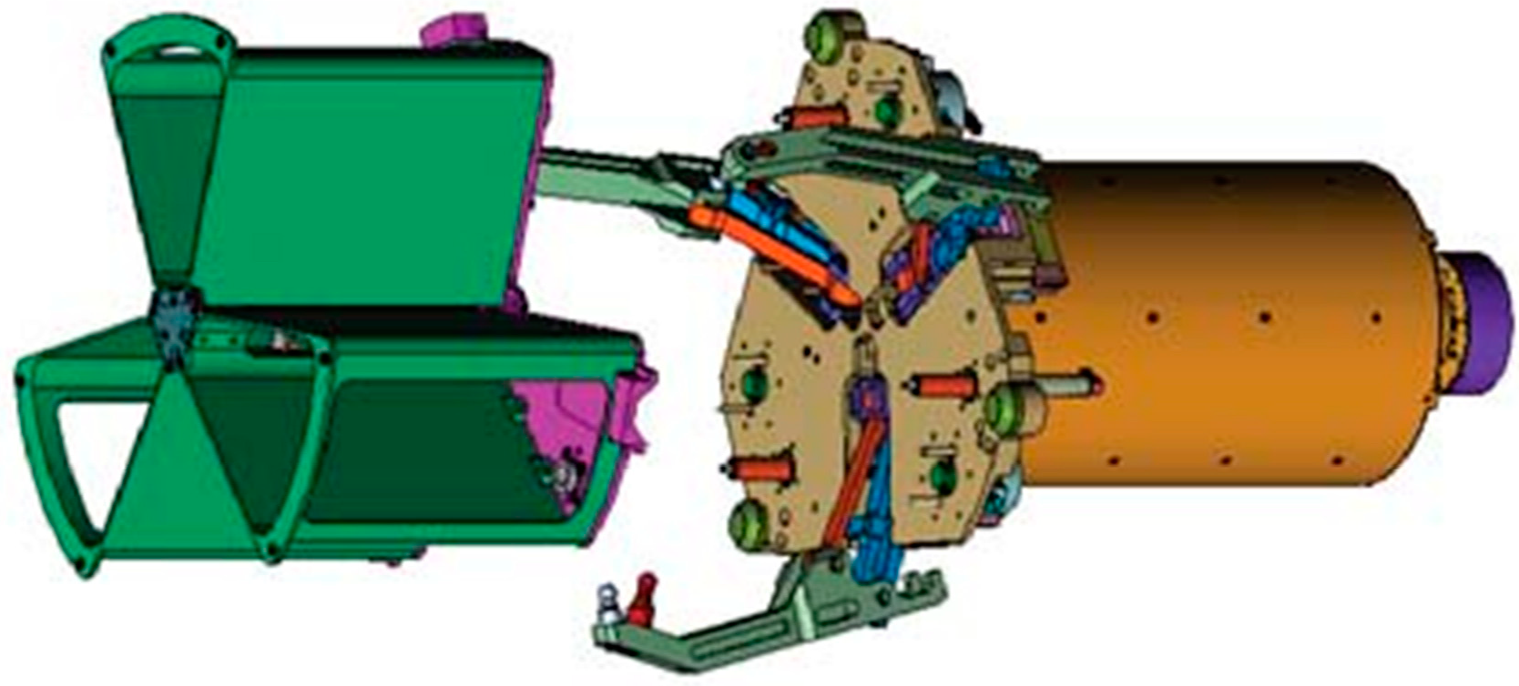
Currently, there have been some studies of active capture docking mechanisms [8]. U.S. Orbit Express is a docking mechanism utilizing a three-finger configuration, which was validated on-orbit in March 2007 [9,10]. The active part contains a three-linked-finger mechanism, seen in Figure 1, which opens its spring-driven fingers before docking to form a large capture space, and is driven by a single motor during the docking process to capture and correct a three-petal passive docking part. The end-effector of the passive part is installed with hooks that cooperate with the fingers to keep the connection. The rubber material at the end of the fingertips provides cushioning and collision force control. However, this three-finger docking mechanism utilizes a central configuration, which is not able to form a natural center channel to transfer the sample or other objects between spacecraft. The docking mechanism of Japan’s Experimental Satellite VII (ETS-VII) utilizes a claw configuration and completed the first on-orbit docking in July 1998 [11,12]. The active part contains three jaw mechanisms, which can be driven independently, and the passive part contains three sets of locking handles, which can realize the capture, correction and connection of two spacecraft. The natural center channel is formed by using the peripheral configuration and can be used for arranging the circuit and liquid replenishment device, but its capture performance is a little poor [12]. The Autonomous Micro-Satellite Docking System (AMDS) led by Michigan Aerospace Corporation (MAC) contains an active part of the retractable flexible rod and a passive part of the tapered structure. The passive part cooperates with the active flexible rod for capture. The magnetic force at the top of the rod achieves initial connection retention, and the flexible rod is pulled back to achieve alignment and structural connection through three locating pins. However, the flexible rod is difficult to validate on the Earth’s gravity [13,14,15], and the centered configuration is not conducive to form the item transfer channel, so AMDS has not been validated yet.

Figure 1.
Orbital Express docking mechanism [10].
This paper focuses on the lunar sample return mission, which requires the completion of docking between two unmanned spacecraft on lunar orbit to realize sample transfer. The mass of the two spacecraft docked on lunar orbit is about 2.0 tons and 0.4 tons. Their absolute mass is smaller, but the relative mass ratio is much larger, compared with the low-Earth-orbit spacecraft. The docking mechanism needs to automatically accomplish the capture correction and connection hold function of the two spacecraft on lunar orbit, in the middle of which, a channel for sample transfer needs to be formed. Therefore, the authors of this paper present the design of a new type of docking mechanism with a peripheral configuration of the active capture claw.
The design of this docking mechanism is very challenging due to the requirements of being lightweight and having miniaturization, where the capture correction and connection hold functions will be realized by the single mechanism. In the design of the docking mechanism, the functions of capture correction and connection hold give different requirements of the loads on the docking mechanism. During the capture correction process, small mass spacecraft are prone to bounce back at high speeds due to the excessive collision forces, resulting in capture failures. Active capture motion introduces additional energy that also increases the collision force. Excessive collision forces may also cause structural damage. Therefore, the capture correction process expects small contact collision loads. However, during the connection hold process after the capture correction is completed, the docking mechanism is required to withstand loads from multiple directions of the docking surface to ensure the stability of the combined spacecraft [16]. Therefore, a high load-carrying capacity is desired during the connection hold process. The design of the stiffness of the docking mechanism directly affects the force load between the docking mechanisms, and it is very important to analyze and design the stiffness of the docking mechanism. Selecting the appropriate stiffness to control the loads between the docking mechanisms is the key technique in the design of docking mechanisms. The ETS-VII of Japan requires collision avoidance processes, resulting in poor capture performance. The Orbit Express of the U.S. reduces the collision force by the damping of the rubber material at the end of the docking mechanism, but at the same time, it is not favorable to maintain the connection after docking due to the low stiffness of the connection. The existing docking mechanism stiffness design research is so limited that it is difficult to guide the active capture claw docking mechanism stiffness design. Therefore, in this paper, the stiffness design of the docking mechanism is carried out in depth.
The second part of this paper introduces the lunar sample return docking mission and the whole docking process. The third part introduces the general design idea. The fourth part introduces the stiffness design of the capture correction process. The fifth part introduces the stiffness design of the connection hold process. The sixth part introduces the simulation verification. The general design mainly adopts the exploratory research method. The preliminary verification is carried out by the quantitative analysis method and the simulation method. On the basis of the collision dynamics theory analysis, the model is further established by MSC ADAMS and Abaqus, and the simulation verification is carried out. The real product is verified by the flight mission. The last part is the conclusion.
2. Active Capture Claw-Type Docking Mechanism
2.1. Docking Mechanism Design
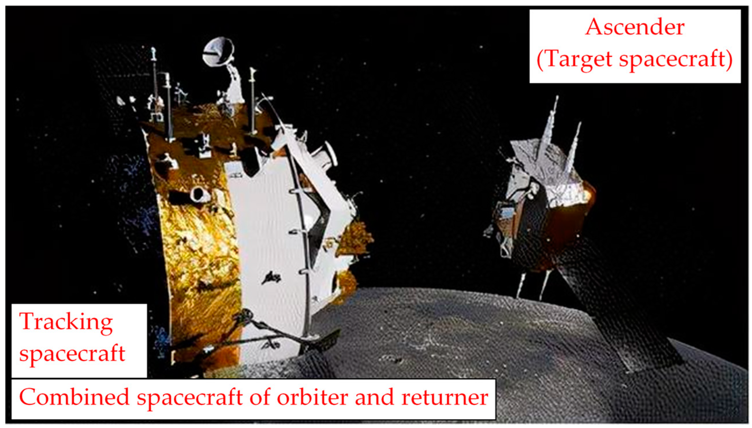
The Lunar Sample Return Explorer consists of an orbiter, a returner, a lander and an ascender. During rendezvous and docking on lunar orbit, the ascender (the right side in Figure 2), which carries the sample container, acts as the target spacecraft and is fitted with a passive docking mechanism, while the combined spacecraft of the orbiter and returner, consisting of the orbiter and the returner, is fitted with an active docking mechanism and acts as the tracking spacecraft (the left side in Figure 2).
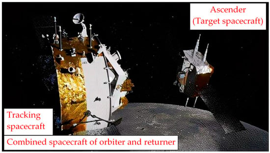
Figure 2.
Lunar-orbit rendezvous and docking mission.
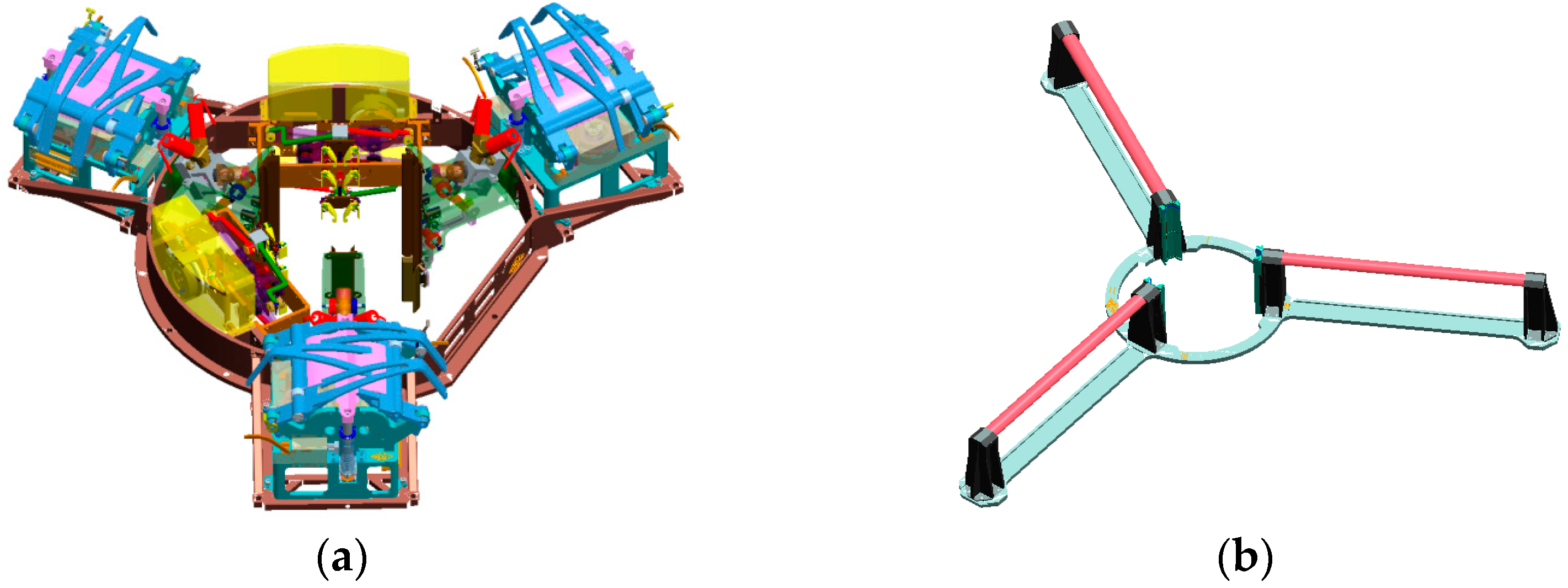
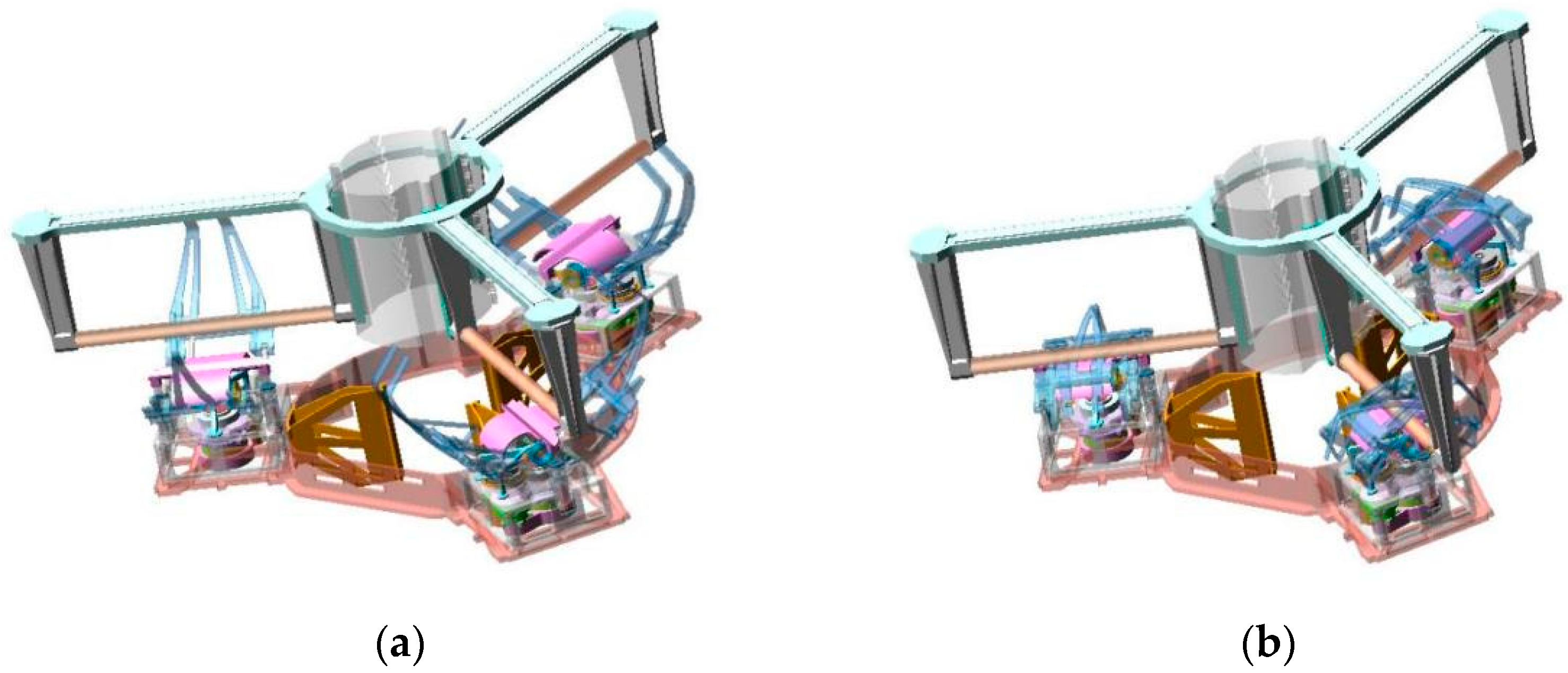
To accomplish the docking mission between the tracking spacecraft and the target spacecraft on lunar orbit, a new active capture claw-type docking mechanism is designed, consisting of two parts, the Active Docking Mechanism (ADM) and the Passive Docking Mechanism (PDM), seen in Figure 3. The docking mechanism adopts a peripheral configuration with a natural channel formed in the center for sample transfer. The active docking mechanism consists of three sets of independently actuated gripper mechanisms, which are responsible for capture correction and connection hold functions. The passive docking mechanism consists of three sets of locking handles, which are distributed in the circumferential position. It has a simple structure and is lightweight; thus, it has significant advantages in the processes of lunar landing, lunar surface work and ascent and takeoff.
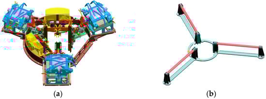
Figure 3.
Composition of the docking mechanism. (a) Active docking mechanism. (b) Passive docking mechanism.
The docking function is the basis to realize the sample transfer mission, which requires the completion of the initial connection between the spacecraft under the initial docking condition deviation. The claw-type docking mechanism is designed to actively capture targets that meet the initial conditions for docking using an active capture strategy. The docking mechanism performs the functions of capture, alignment, locking and holding; provides an accurately aligned transfer path for the transfer mechanism; and withstands the loads on the docking surface during the joint flight. In order to meet requirements, such as repeated docking in orbit, the mechanism also needs to be able to realize separation functions.
The masses and moment of inertia of the two docked spacecraft are shown in Table 1.

Table 1.
Mass characteristics of spacecraft and ascender during docking.
2.2. Working Principle of Docking Mechanism
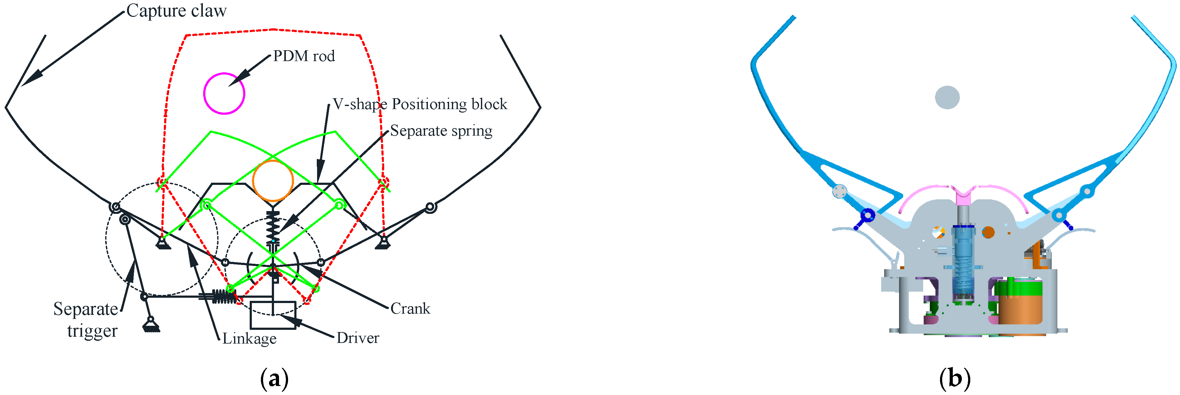
The docking function adopts a modular design, with three sets of claw-type mechanisms evenly distributed along the circumference. Each claw-type mechanism is responsible for capturing and locking one set of locking handles and is capable of realizing the constraint of three degrees of freedom of the locking handles, including two translational degrees of freedom along the X and Z directions and one rotational degree of freedom around the Z axis. The three sets of locking handle axes are not parallel and have an angle of 120° relative to each other. The locking handles enable the three sets of claw-type mechanisms to realize the constraint of the other three degrees of freedom of the locking handle, including the constraint of one degree of freedom of translation along the Y direction and the constraint of two degrees of freedom of rotation around the YZ axis. The combination of three sets of claw-type mechanisms realizes the complete constraint of six degrees of freedom between the active and passive spacecraft, which strengthens the connection’s load-bearing capacity. The working principle of the claw mechanism is shown in Figure 4, where the mechanism in the open-claw position is shown in Figure 4b in order to better understand the working principle in Figure 4a. Two sets of crank-rocker four-link mechanisms are used, including drive crank, intermediate linkage, rocker, capture claw and housing. The left and right claws are fixedly connected to the rockers in the two sets of four-link mechanisms. The rocker can drive the claws for a wide range of capturing, correcting and locking motions because it is capable of a wide range of motion. The left and right cranks are connected together by bevel gears. The two cranks are driven by a drive mechanism to synchronize the reverse movement of the two cranks.
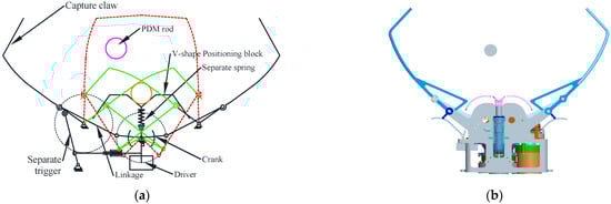
Figure 4.
Working principle of the claw-type mechanism. (a) Working principle. (b) Open-claw position.
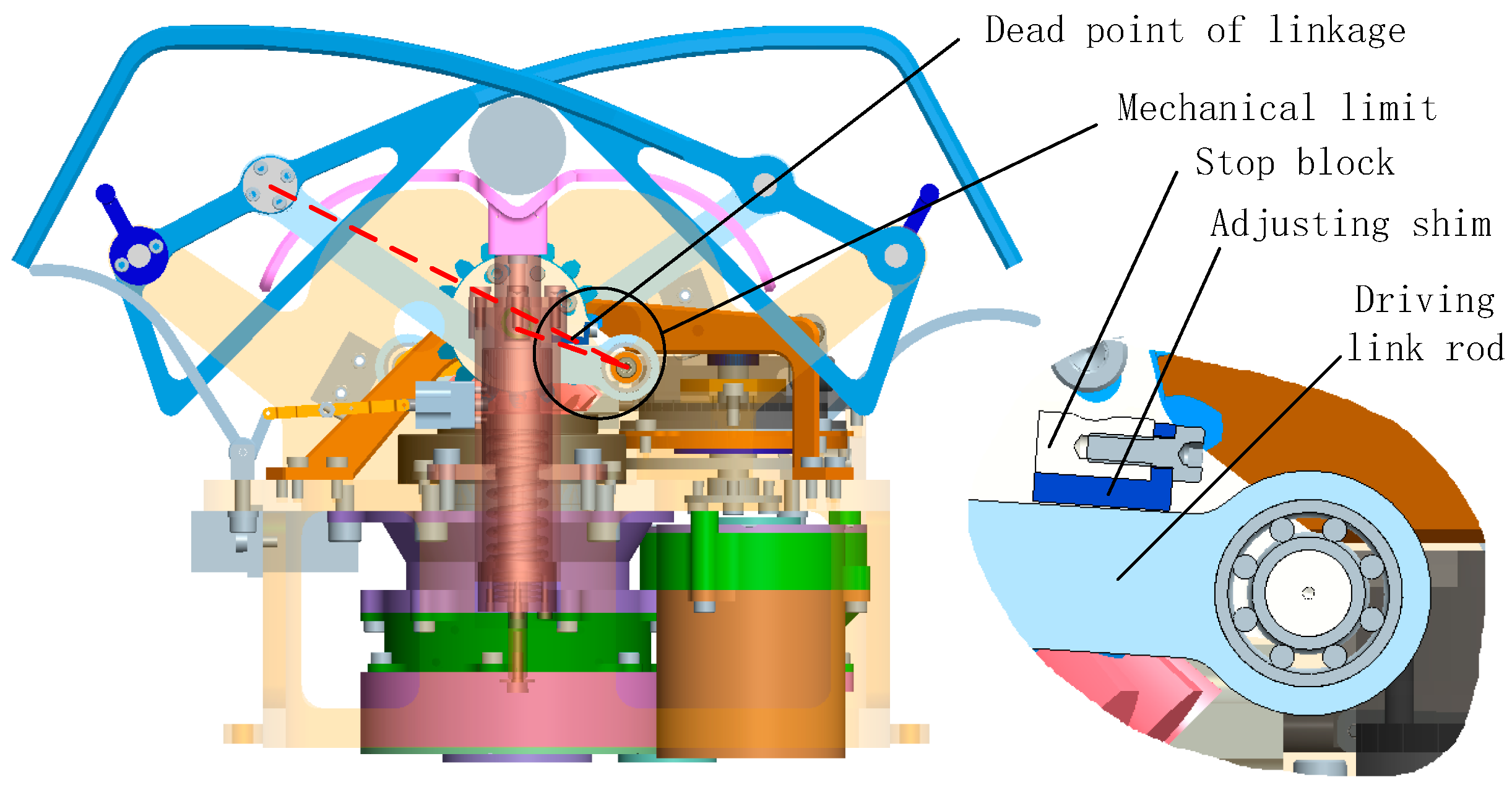
A V-block is installed in the center locking position of the claw-type mechanism for correction and positioning. The V-block and the left and right locking claws work together to realize the positioning correction of the locking handle in Figure 5a. The claws are locked in position by means of a dead center plus mechanical limits and a unidirectional transmission of the claw drive; the locking position can be seen in Figure 5b. The dead point and mechanical limit principle are shown in Figure 6. By combining the dead point and mechanical limit, the mechanism can maintain the locking position.
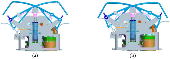
Figure 5.
The correction and locking of claw-type mechanism. (a) Correction position. (b) Locking position.
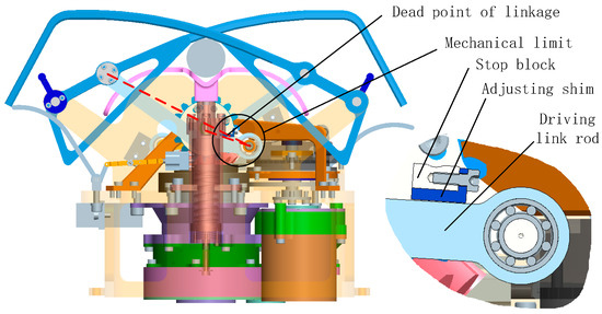
Figure 6.
Principe of dead-center position of the claw-type mechanism and mechanical limiting.
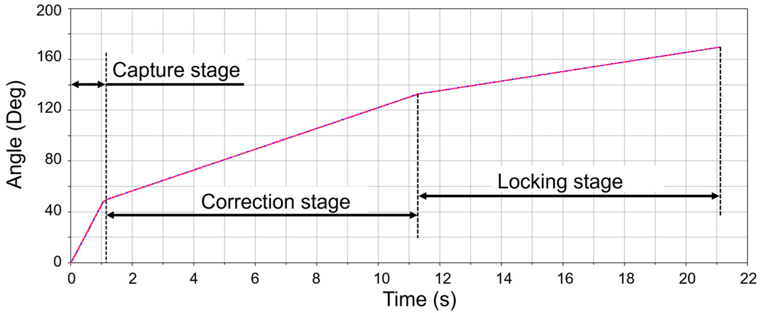
In order to ensure the different requirements of different working stages, in the capture stage, the motor works in high speed to realize the fast closing of the claw. In other stages, the motor speed is appropriately reduced to realize slow correction and locking so that the positioning accuracy of docking can be improved. The total stroke of the rotation is about 170° from the open state to the end of the locking. The whole stroke is divided into several stages, such as capture, correction and locking, and can be finished in 21 s [17], seen in Figure 7. After the docking is completed, if the separation function needs to be performed, the claw-type mechanism can be actively opened to release the lock handle. This gives the docking mechanism the ability to repeat the docking process on orbit in order to deal with various failures during the mission.
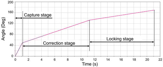
Figure 7.
Variation curve of the angle of the claw.
2.3. Working Process of the Docking Mechanism
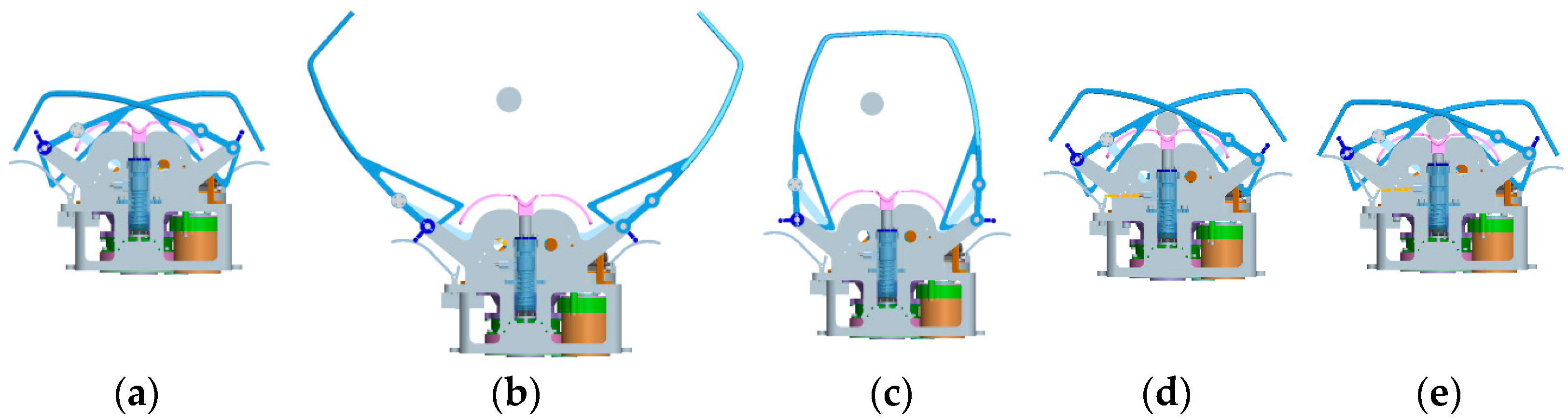
The claw docking mechanism adopts a modular design. Three sets of claw-type mechanisms work independently to move synchronously to realize the docking function. The working process of a single claw is shown in Figure 8. During the launch, the claw-type mechanism is retracted to reduce the overall height of the whole detector system. In order to fulfill the capture function, the capture mechanism needs to satisfy the inclusiveness requirement with respect to the maximum positional deviation of the locking handle. Before executing the capture command, the capture mechanism is able to adapt to the positional inclusion requirement under the combination of the various positional deviations of the initial conditions, allowing the locking handle to enter into the space that can be captured by the holding claw. When the capture action is executed, the claw can form a closed capture space to the locking handle to ensure reliable capture. The correction process will eliminate the positional deviation between the two sets of docking mechanisms and ensure the alignment of the center axis of the spacecraft, laying the foundation for the subsequent sample transfer mission. The claw mechanism would be subjected to multidirectional loads between the docking surfaces to ensure the stiffness of the connection between the spacecraft.
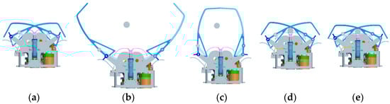
Figure 8.
The calibration and locking of claw-type mechanism. (a) Launch state; (b) Docking preparation; (c) Capture; (d) Correction; (e) Locking.
3. Principle of Stiffness Design
Stiffness design has a significant impact on the function, performance and quality of the docking mechanism and is one of the key points in the design of docking mechanisms. Due to the difference in requirements between the capture process and the connection process, large docking mechanisms generally have separate stiffness designs for the flexible capture system and the rigid connection system to meet the functional specifications. In addition, there is a need for a synergistic design of layouts and work strokes [18,19,20]. Generally, the flexible capture system is installed in the center position, which mainly solves the design problems of stiffness and damping parameters, such as collision rebound and energy dissipation, while the rigid connection system is installed in the peripheral position, which mainly solves the problems of sealing, large load bearing and reliable separation, seen in Figure 9. This design, which requires two systems, a flexible capture system and a rigid connection system, is mainly used for the docking mechanism of a manned spacecraft as shown in Figure 9 [21,22,23,24]. However, the large mass and size of the manned spacecraft docking mechanism are not suitable for docking missions of small spacecraft.

Figure 9.
Manned spacecraft docking mechanism.
The design of the stiffness of the active capture and claw-type docking mechanism is also divided into two parts: capture correction and connection hold. The stiffness of the capture correction process is mainly realized through the structural optimization design of the claw to ensure that the collision load matches the structural strength during the docking process. The stiffness of the connection hold process is mainly for the demand of connection bearing. Through the force analysis of the connecting rod mechanism, the strength and transmission requirements are proposed to ensure the connection hold function of the docking mechanism. Both stiffness properties are integrated into one single claw-type mechanism through coordinated optimization. Moreover, this stiffness-integrated design effectively reduces the mass and envelope size of the docking mechanism compared to the traditional two stiffness-independent designs.
4. Stiffness Design of Capture Process
As the first step in the docking process, the capture function is the foundation of the docking function. During the capture process, due to the relative lateral and axial velocities between the two spacecraft, the collisions will happen between the active and passive docking mechanisms. Although the collision force of the claw docking mechanism in this paper is significantly lower than that of the large docking mechanism, it still has a huge impact on the docking performance and structural strength, so it is necessary to analyze and propose reasonable design indexes of the claw strength and the equivalent stiffness.
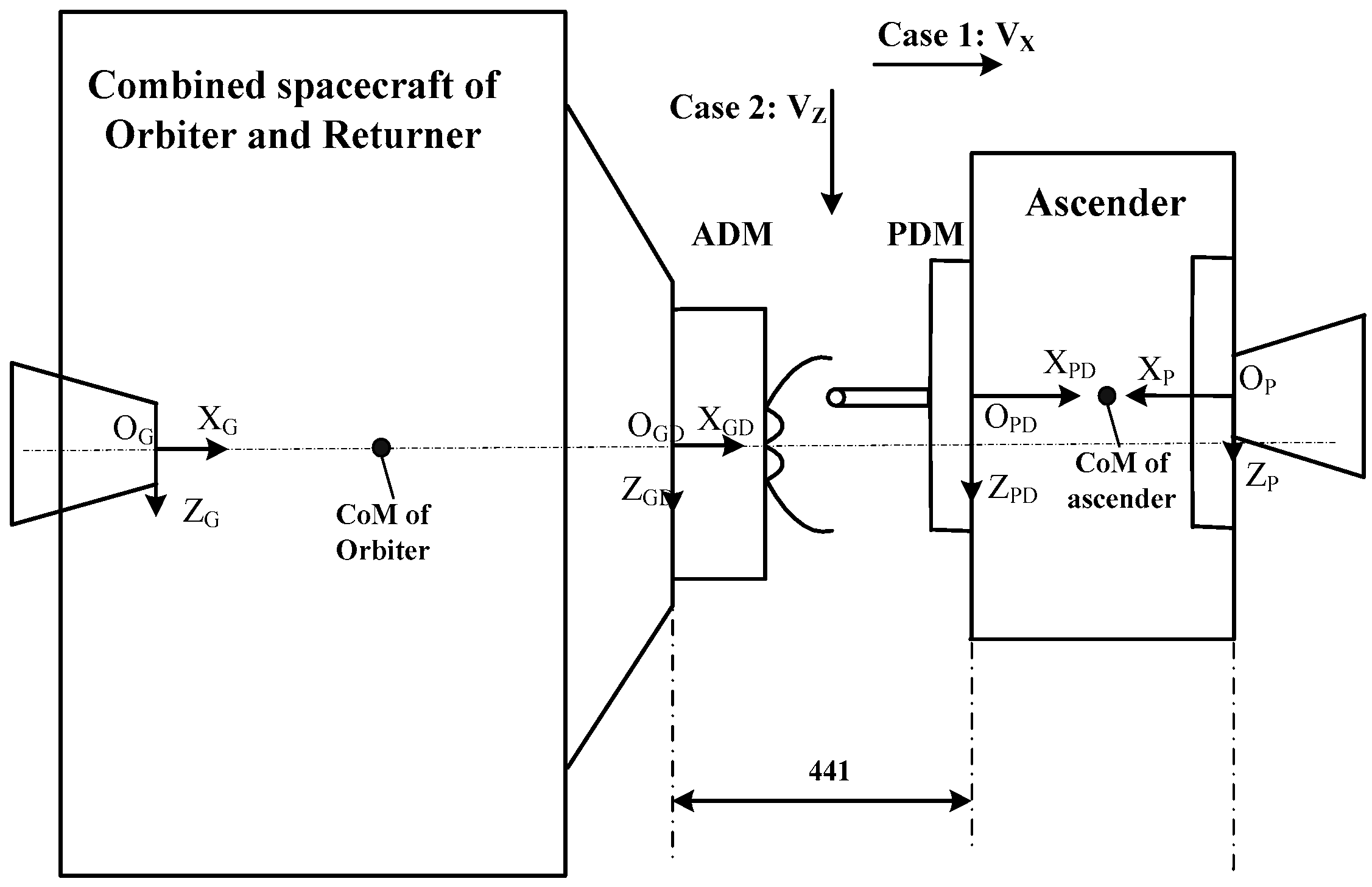
The initial deviation condition captured by the docking mechanism is called the initial docking condition and is the basic input condition for the design of the docking mechanism. The initial docking conditions are defined within the coordinate system of the two sets of docking surfaces, seen in Figure 10. OG-XGYGZG is the mechanical coordinate system of the tracking spacecraft (combined spacecraft of the orbiter and returner). OP-XPYPZP is the mechanical coordinate system of the target spacecraft (ascender). OPD-XPDYPDZPD is the docking surface coordinate system of the target spacecraft (ascender). OGD-XGDYGDZGD is the docking surface coordinate system of the tracking spacecraft (ascender).

Figure 10.
Definition of the docking process coordinate systems.
The collision process between docking mechanisms needs to be considered when docking mechanisms are captured. The collision is mainly caused by the relative velocities between the active and passive docking mechanisms, including the initial relative velocity between the two spacecraft and the velocity generated by the capture motion of the holding claws. The forces generated by the collision can lead to changes in the motion of the spacecraft, causing a risk of separation. Therefore, the claw-type mechanism is required to move rapidly before and after the first collision to form a closed space to ensure that there is no further separation between the two docked spacecraft. The rapid motion of the claw is closely coupled with the magnitude of the initial collision load, which is a key point for modeling and analysis.
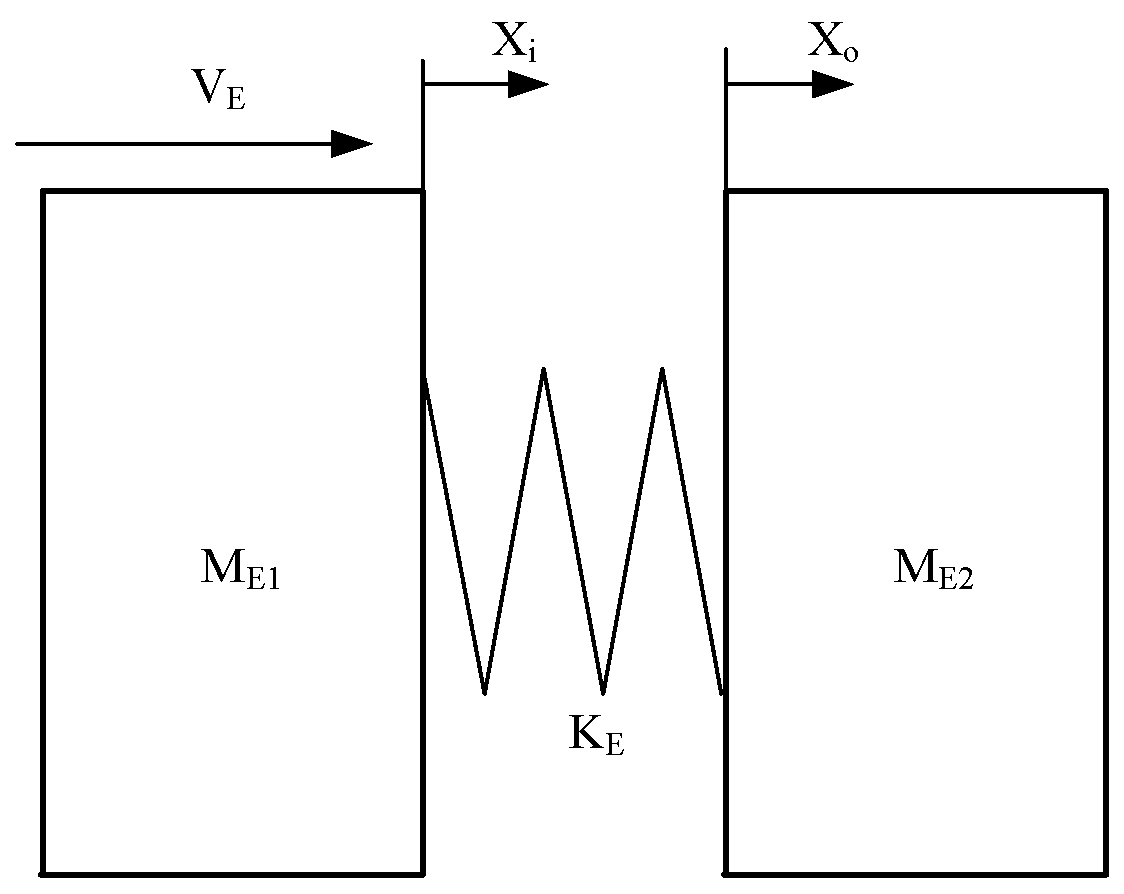
Collisions in any direction can be decomposed into a combination of axial and lateral collisions. In order to simplify the analysis process, the force cases of axial collision (Case 1) and lateral collision (Case 2), as shown in Figure 10, were modeled and analyzed separately. The collision at the location of the initial contact of the docking mechanism produces elastic deformations and causes the changing movements of the spacecraft. This process will be equivalent to an elastic collision model in theoretical calculations, seen in Figure 11. For the other collision cases, under the condition that the same control method was used for the initial conditions, it can be decomposed into a combination of the two working conditions. As a result, the peak value of the collision load remains unchanged.
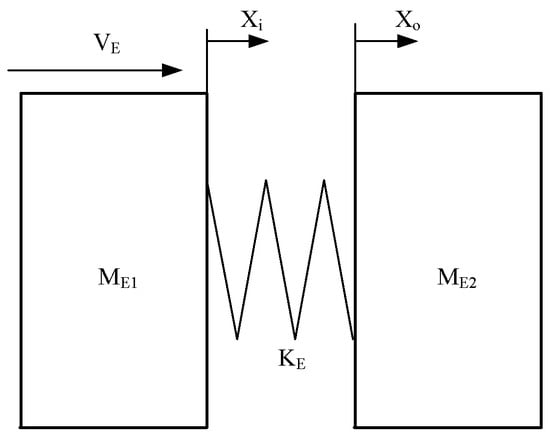
Figure 11.
Equivalent theoretical model of two spacecraft docking collision dynamics.
Losses, such as frictional resistance and material damping, have a small effect during collisions, so these losses are neglected. Assuming that energy is conserved during the collision of the two spacecraft, that the initial relative kinetic energy is converted to elastic potential energy and that a collision load is generated at the point of contact, the following equations can be written:
where xi is the displacement of the active tracking spacecraft and x0 is the displacement of the passive target spacecraft and a1 and a2 are the accelerations of two spacecraft. F is the collision force; is the equivalent stiffness of impact point; and are the equivalent masses of two spacecraft; and is the initial relative velocity of two spacecraft. Considering that the lateral deflection of the axial collision is small, the deflection motion and its effects are ignored in the model for Case 1. The two working condition parameters were calculated differently, and their differences are shown in Table 2.
Table 2.
Description of parameters for equivalent models.
When the condition is satisfied, the relative velocity of the two spacecraft is zero. At this time, no more structures are compressed and the collision force between the spacecraft reaches its maximum value. The time of the lock handle entering the capture range, collision, recovery and finally rebound separation to escape from the capture range can be used to hold the claw to form a closed space. Solving the above Equations (1)–(5) leads to the result:
where is the equivalent mass of the two spacecraft. According to Equation (7), it can be seen that the equivalent stiffness and equivalent collision velocity of the contact need to be optimally designed in order to control the collision load during the capture process when the mass characteristics of the spacecraft are determined. The main design constraints are:
- Less stiffness reduces the maximum crash load and increases the space available for claw closure. However, too little stiffness can lead to an insufficient structural load-bearing capacity for subsequent calibration and locking functions, or even increase the risk of large end deformation or structural damage during calibration or of escape of the locking handle from the capture space;
- The most significant influence on the collision load is the equivalent relative motion velocity. In addition to the initial relative velocity, the velocity of the claw’s own movement also has a large influence. Slow capture velocity is effective in reducing collision loads, but is not conducive to rapid formation of closed spaces. Excessive capture velocity can cause a dramatic increase in the collision load, leading to an increase in the weight of the claw-type mechanism and drive mechanism, which is not conducive to the lightweight design of the mechanism. So, the capture performance and light weight need to be balanced in design;
In summary, the claw-type mechanism stiffness design needs to be lightweight on the basis of multiparameter and multiconstraint design in terms of collision stiffness and capture motion velocity, etc. Considering the driving power of the claw-type mechanism and the load-bearing strength, the lock handle and other structures are designed to have a maximum load limit of 300 N. The velocity of the claw’s capture motion is influenced by the drive power and the drive mechanism, so the maximum velocity of the collision position on the claw is designed to be 0.1 m/s. According to the envelope size of the spacecraft and the layout, the distance between collision position and the center of mass of the active and passive spacecraft is 1.7 ± 0.05 m and 0.55 ± 0.05 m. By substituting the known parameters into Equation (7), the calculation result can be obtained that the contact stiffness of the claw at the collision position should be satisfied with less than 25 N/mm, so that the collision load is not greater than 300 N.
5. Stiffness Design of Connection Hold Process
In order to ensure that the claw can withstand sufficient vibration loads in the subsequent stages to meet the requirements of continued operation, it is also necessary to carry out a stiffness design analysis for the claw-type docking mechanism. After the two spacecraft have completed docking, the claw mechanism also needs to have the ability to overcome various external loads. The docking surfaces should not separate, and the positioning accuracy of the docking can be maintained. According to the attitude control requirements of the combined spacecraft after docking, the external loads on the docking surface are about a 30 Nm bending moment and 25 N axial tension under the action of various attitude control engines.
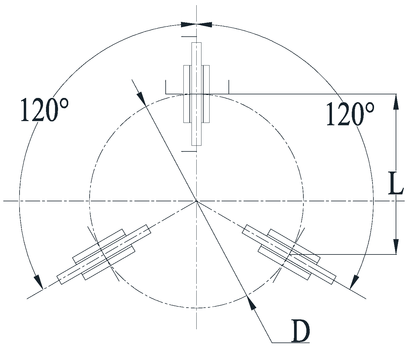
The claw-type mechanism adopts a crank-rocker mechanism to drive the connecting rod over the dead center to realize the self-locking of the mechanism in the locking state. In addition, the claw drive mechanism is also self-locking in the reverse direction. Therefore, in the locked state, the load-bearing function of the docking mechanism is mainly realized by the locking claw structure. In order to maintain the locking state, the load capacity of the combination of multiple claw-type mechanisms should be larger than all external superimposed loads. The worst case of a moment load is the sum of the moment equivalent tension and external tension in one single set of claws. For the three-point layout, the bending moment formed by rotating around the axis of the two sets of claws produces the greatest tensile load on a single set of claws. The corresponding flipping arm of force is, in the case of a 120° distribution of the three locking points, equal to 1.5 times the radius of the distribution circle, seen in Figure 12.
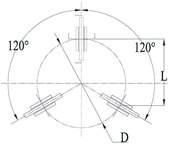
Figure 12.
Load-bearing layout of docking surface.
Considering the number of claw mechanisms and the diameter of the distribution circle and other parameters, the requirements for a single set of claw mechanisms to carry external tension loads are:
where is the average distribution diameter of the claw-type mechanism (about 700 mm), is the external bending moment, and is the external axial tension. Substituting the above parameters into Equation (8) gives:
In this paper, we took the value .
In order to reduce the tolerance requirements for subsequent sample transfer, the accuracy of the docking mechanism needs to ensure that the maximum deformation under the rated load is [25]. In addition, the left and right sides have claws to carry the load together. As a result, the stiffness of the locking point of the claw under the external load is not less than . It can be seen that the stiffness requirements of the capture process of 25 N/mm and the connection hold process of 85 N/mm are not consistent. Therefore, it is necessary to optimize the design using a variable stiffness configuration of the claw-type mechanism to ensure that both functions are effective.
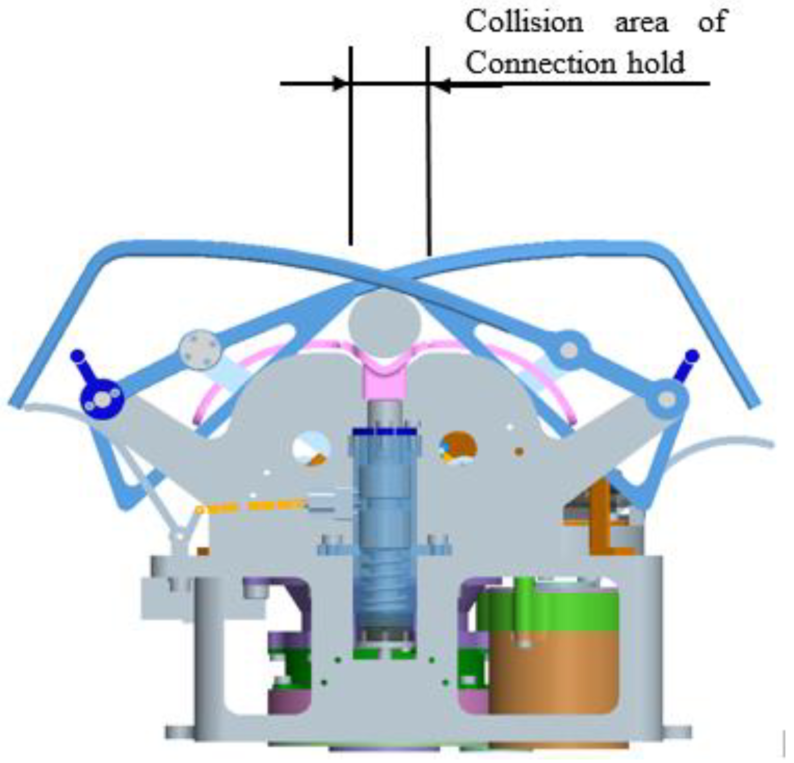
The design of the left and right locking claws mainly considers the capture process using the middle and upper part of the claws. The left and right claws are designed with equal stiffness and strength to meet the needs of the capture load. At the same time, in order to ensure the compatibility of the left and right claws in the process of grasping, single and double claw configurations are used. The connection hold function requires a reinforcement at the root position of the claws, as shown in Figure 13. Therefore, the load-bearing stiffness of the claw is enhanced by increasing the structural cross-section and using reinforcement bars. Considering the lightweight and strength requirements, the claw material is made of titanium alloy TC4, and the processing method of CNC machining is adopted. The results of the design are shown in Figure 14.

Figure 13.
Stiffness design area of connection hold.
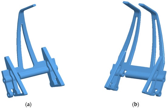
Figure 14.
Structure of the left and right locking claws. (a) Left locking claw. (b) Right locking claw.
Using Abaqus/Stand 6.11-2 software, finite element modeling analysis was applied for the designed claws. A desired payload was applied to the claw-type structure at the nominal height to analyze the structural deformation and stiffness performance, seen in Figure 15. From the figure, it can be seen that the average stiffness of the working section of the single-finger claw during capture correction is 22.1 N/mm, and the average stiffness of the working section of the double-finger claw during capture correction is 22.0 N/mm. The maximum deformation under the collision load is about 7.6 mm. The working section for the connection hold of the left and right claws was strengthened to have higher stiffness, with an average stiffness of 95 N/mm, which meets the requirements for the connection hold process.
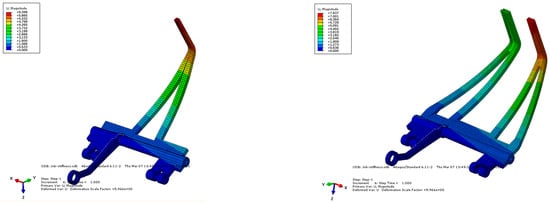
Figure 15.
FEM analysis of claw stiffness during capture process.
6. Analysis and Verification
6.1. Simulation Analysis
Based on the design of the claw-type docking mechanism, using MSC ADAMS software, a digital prototype simulation model was established, seen in Figure 16. The model was used for the simulation and analysis of docking dynamics, and Figure 16a shows the initial state of docking, and Figure 16b shows the final state of docking.
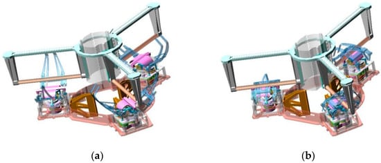
Figure 16.
Simulation model of claw-type docking dynamics. (a) Initial state of docking. (b) Final state of docking.
A simulation analysis of docking dynamics under a variety of typical working conditions was carried out through the simulation model in Figure 16 using MSC ADAMS software and its embedded algorithms, mainly considering the capture performance under single and combined limit deviations in the initial conditions of docking and analyzing the collision loads. Lateral displacement and lateral velocity, which have a strong influence on capture performance and collision, were selected. A simulation analysis of the combined working conditions was performed, using the parameter values in Table 3.
Table 3.
Typical initial docking conditions.
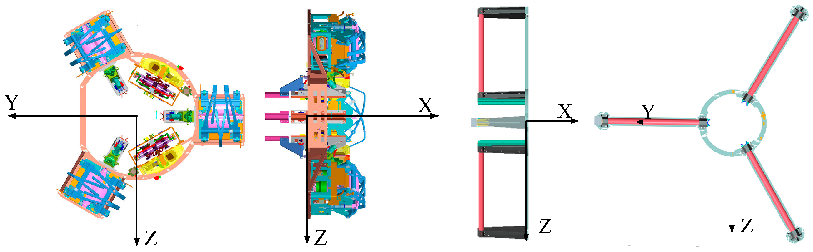
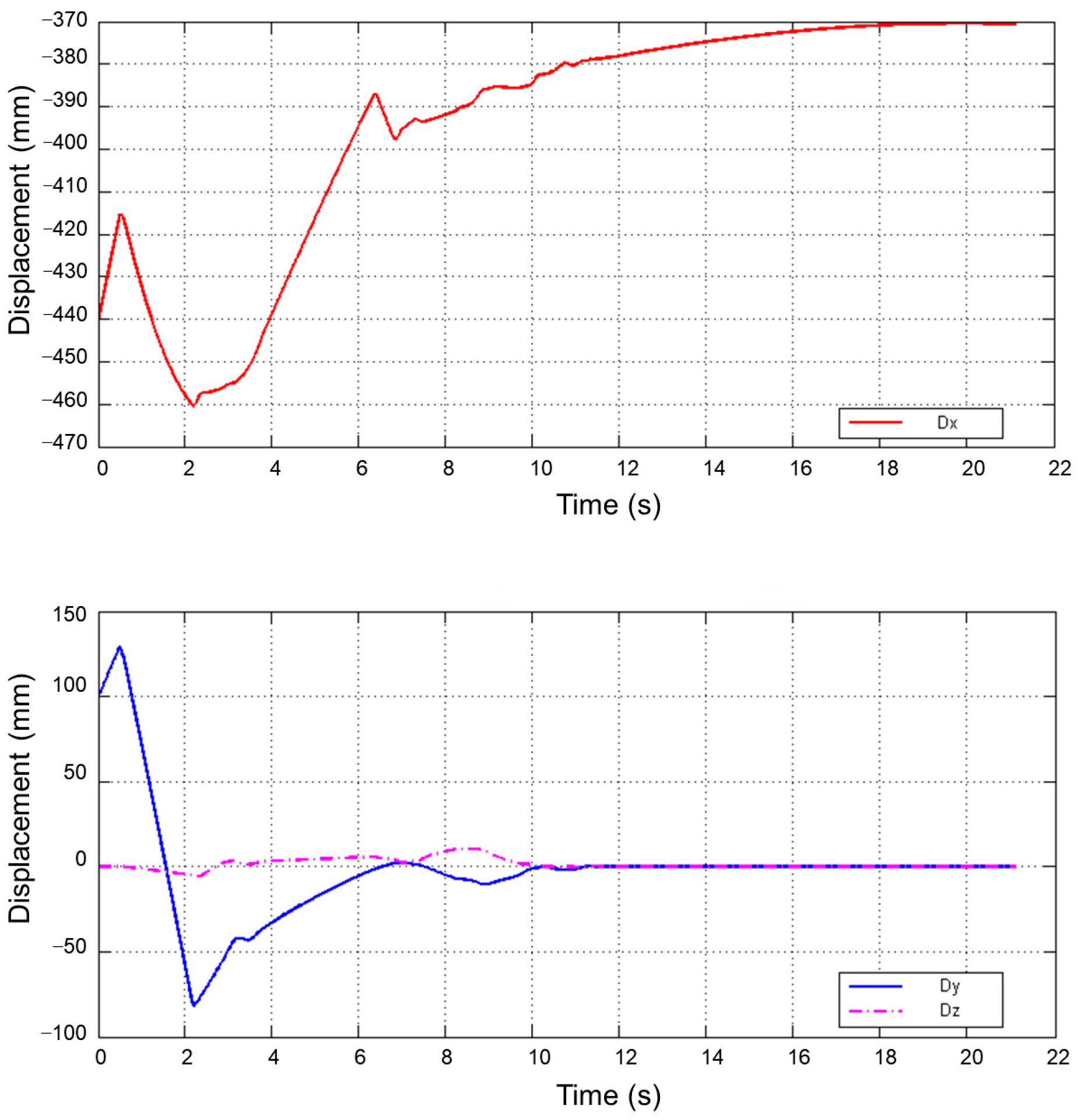
The docking surface coordinate system definition is given in Figure 17. Figure 18 shows the curve of the relative displacement of the docking surface. It can be seen that under the coordinate system of the docking mechanism, the relative displacements of the two spacecraft in three directions gradually converge from the initial deviation to zero, indicating that the docking mechanism is able to accomplish the capture correction successfully.
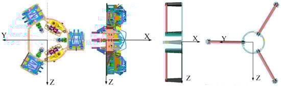
Figure 17.
Docking surface coordinate system definition.
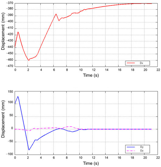
Figure 18.
Curve of the relative displacement of the docking surface.
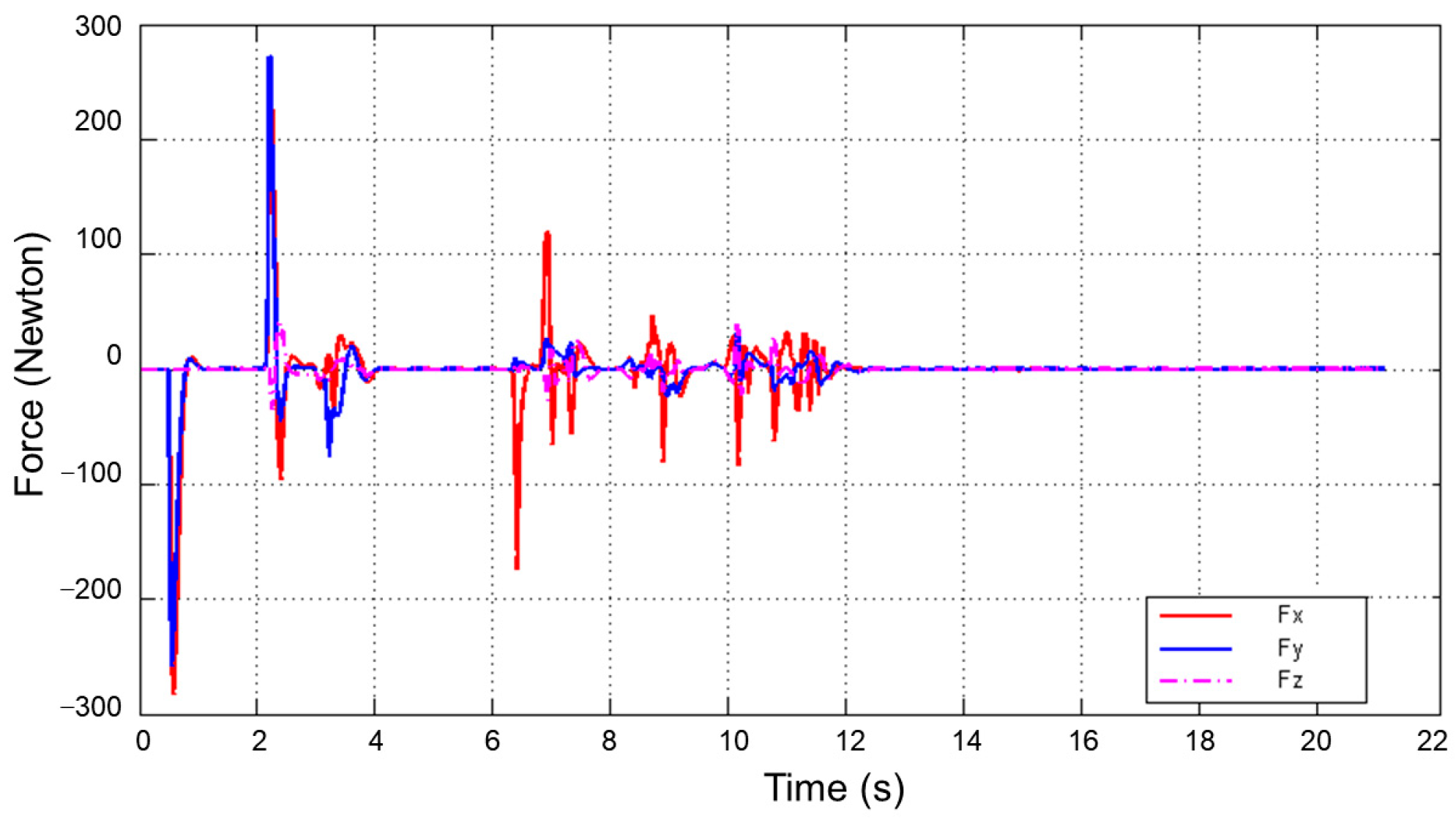
Figure 19 shows the curve of the collision force of the docking mechanism. It can be seen that a slight collision occurred between the docking mechanisms during the docking process. The correction process works successfully. Maximum x-direction collision force is about 290 N; maximum y-direction collision force is about 280 N; maximum z-direction collision force is about 240 N; and the collision load is no more than 300 N. As a result, the stiffness of the docking mechanism is reasonably designed.
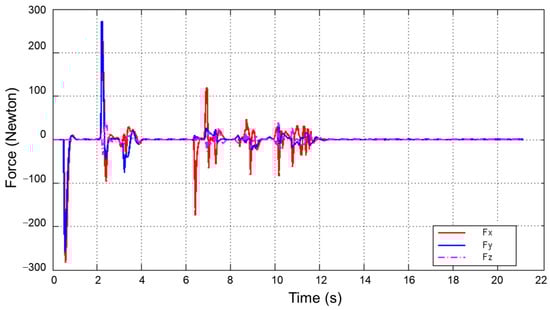
Figure 19.
Curve of the collision force of the docking mechanism.
6.2. Practical Verification
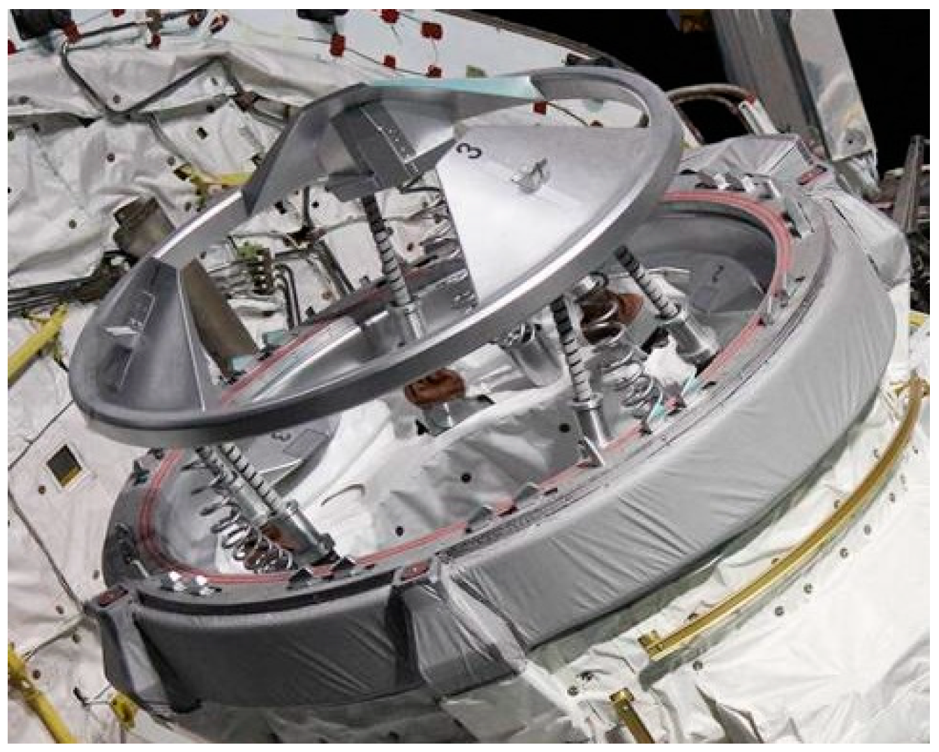
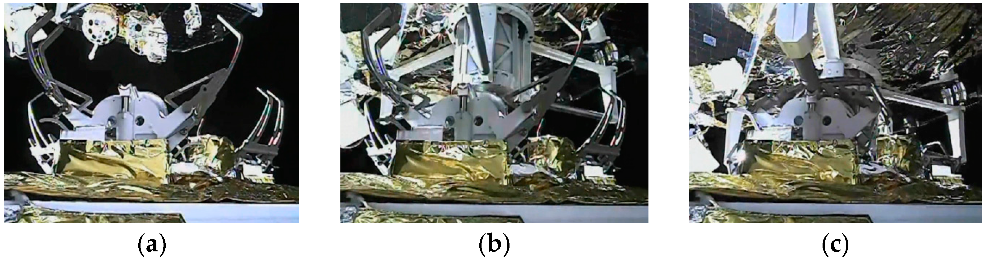
On December 6, 2020, the active capture claw-type docking mechanism successfully completed the docking mission between lunar-orbit spacecraft during the Chang’e V mission of China’s lunar exploration project, seen in Figure 20. The connected state is stable, and it creates a stable transfer channel for sample transfer. During on-orbit operation, the current, moving position and moving time of the docking mechanism were monitored, and the consistency of the telemetry data was better than 96.3%. The successful completion of the on-orbit mission demonstrated that the stiffness of the claw-type docking mechanism was designed correctly and effectively.
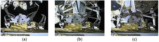
Figure 20.
Active capture docking mechanism on orbit. (a) Approaching stage. (b) Capture stage. (c) Finish stage.
7. Conclusions
In this paper, an active capture claw-type docking mechanism for the lunar sample return mission on orbit is designed. The research focused on the stiffness design of the active capture claw-type docking mechanism. According to the different requirements of the capture correction function and connection hold function, the stiffness of the docking mechanism was designed. By simulating and analyzing the docking mission under typical working conditions, the design was verified to be able to take into account the stiffness requirements of the two functional phases appropriately. The developed active capture claw-type docking mechanism successfully completed the docking mission. The whole working process of the docking mechanism is good, which verifies the correctness and effectiveness of the design in this paper. The novelty of this paper is that a stiffness design method of the active capture claw-type docking mechanism satisfying different stiffness requirements of the capture correction function and connection hold function is proposed. Through the matching design of stiffness demand, the difficulties of multiconstraint design, such as functional integration of claw docking mechanism and lightweight design, have been solved, which can provide a good reference for the subsequent stiffness design of other types of docking mechanisms.
Author Contributions
Conceptualization, W.W. and C.Z.; Methodology, W.W. and C.Z.; software, W.W.; validation, W.W. and C.Q.; Formal Analysis, W.W. and C.Z.; Investigation, W.W. and C.Q.; Resources, L.F. and S.W.; data curation, W.W. and L.F.; writing—Original Draft Preparation, W.W., C.Z., C.Q., L.F. and S.W.; Writing—Review & Editing: W.W. and C.Q.; Visualization, W.W.; supervision, S.W.; project administration, C.Z.; Funding Acquisition: C.Q. and C.Z. All authors have read and agreed to the published version of the manuscript.
Funding
This research was funded by the National Natural Science Foundation of China, grant number 51975351.
Data Availability Statement
The data presented in this study are available on request from the corresponding author. The data are not publicly available due to privacy restrictions.
Conflicts of Interest
The authors declare no conflict of interest.
References
- Zhou, J.P. Space Rendezvous and Docking Technology; National Defense Industry Press: Beijing, China, 2013. [Google Scholar]
- Zhang, C.F. Space Docking Mechanism; Science Press: Beijing, China, 2016. [Google Scholar]
- Shen, T.; Zhang, C.F.; Wang, W.J.; Feng, W.B.; Qiu, H.Y. Dynamic Simulation Analysis of Capture and Buffer System based on Claw-Type Docking Mechanism. Chin. J. Theor. Appl. Mech. 2020, 52, 1590–1598. [Google Scholar]
- Saunders, C.; Lobb, D.; Sweeting, M.; Gao, Y. Building Large Telescopes in Orbit Using Small Satellites. Acta Astronaut. 2017, 141, 183–195. [Google Scholar] [CrossRef]
- Chiu, S.W. Promoting International Co-Operation in the Age of Global Space Governance—A Study On On-Orbit Servicing Operations. Acta Astronaut. 2019, 161, 375–381. [Google Scholar] [CrossRef]
- Maeda, K. Present and Future of Small Satellites—Observation and Communication Missions. IEICE Tech. Rep. 2010, 110, 181–187. [Google Scholar]
- Dick, B.N.; Oesch, C.; Rupp, T.W. Linear Actuator System for the NASA Docking System. In Proceedings of the European Space Mechanisms and Tribology Symposium, Hatfield, UK, 20–22 September 2017. [Google Scholar]
- Zhao, Z.; Shi, J.W.; Wang, W.J.; Liu, Z. Research on Modeling Method of Docking Dynamics of Small Weak Impact Docking Mechanisms. Deep Space Explor. 2011, 9, 37–41. [Google Scholar]
- Leinz, M.R.; Chen, C.T.; Scott, P.; Gaumer, W.; Sabasteanski, P.; Beaven, M. Modeling, Simulation, Testing, and Verification of the Orbital Express Autonomous Rendezvous and Capture Sensor System (ARCSS). In Proceedings of the SPIE 6958, Sensors and Systems for Space Applications II, Orlando, FL, USA, 16–20 March 2008; p. 69580C. [Google Scholar]
- Christiansen, S.; Nilson, T. Docking System Mechanism Utilized on Orbital Express Program. 2008. Available online: https://api.semanticscholar.org/CorpusID:59503091 (accessed on 1 January 2014).
- Oda, M. ETS-VII: Achievements, Troubles and Future. In Proceedings of the 6th International Symposium on Artificial Intelligence and Robotics & Automation in Space: i-SAIRAS 2001, Canadian Space Agency, St-Hubert, QC, Canada, 18–22 June 2001. [Google Scholar]
- Oda, M.; Kawano, I.; Kibe, K.; Yamagata, F. ETS-7, a Rendezvous Docking and Space Robot Technology Experiment Satellite—Result of The Engineering Model Development Work. In Proceedings of the 34th SICE Annual Conference, Hokkaido, Japan, 26–28 July 1995. [Google Scholar]
- Gao, F.; Qi, C.K.; Ren, A.Y.; Zhao, X.C.; Cao, R.; Sun, Q.; Wang, Q.; Hu, Y.; He, J.; Jin, Z.L.; et al. Hardware-in-the-Loop Simulation for the Contact Dynamic Process of Flying Objects in Space. Sci. China Technol. Sci. 2016, 59, 1167–1175. [Google Scholar] [CrossRef]
- Qi, C.K.; Li, D.J.; Hu, Y.; Zheng, Y.; Wang, W.J.; Shou, X.; Gao, F. Learning-Based Distortion Compensation for a Hybrid Simulator of Space Docking. IEEE Robot. Autom. Lett. 2023, 8, 3446–3453. [Google Scholar] [CrossRef]
- Han, W.; Huang, Y.Y.; Chen, X.Q.; Zhang, X. Flexible cone impact dynamics based on space probe-cone docking mechanism. Sci. China Phys. Mech. Astron. 2014, 57, 128–137. [Google Scholar] [CrossRef]
- Ge, X.Y.; Zhou, Q.X.; Liu, Z.Q. Assessment of Space Station On-Orbit Maintenance Task Complexity. Reliab. Eng. Syst. Saf. 2019, 193, 106661. [Google Scholar] [CrossRef]
- Chen, J.Y.; Wang, J.; Fu, L.J.; Yuan, Y.; Hou, C.; Yan, D. Design and Implementation of Control System for Lunar Orbit Docking and Sample Transfer Mechanism. Aerosp. Shanghai 2022, 39 (Suppl. S1), 54–60. [Google Scholar]
- Chen, C.Z.; Nie, H.; Chen, J.B.; Wang, X.T. Analysis of force transmissibility performance of low impact docking mechanism during capturing process. J. Nanjing Univ. Aeronaut. Astronaut. 2014, 22, 301–316. [Google Scholar] [CrossRef]
- Chen, B.D.; Tang, P. The Technology Development of Docking Mechanism System. Aerosp. Shanghai 2005, 22, 6–8, 61. [Google Scholar]
- Zhao, Y.; Cao, X.B.; Sun, Z.W. Dynamic testing method for space docking mechanism. Aircr. Eng. Aerosp. Technol. 2003, 75, 600–604. [Google Scholar]
- Lou, W.H.; Zhang, B.N. Technical Developments in Space Docking Mechanisms. Spacecr. Eng. 1994, 3, 1–22. [Google Scholar]
- Li, J.G.; Ding, J.; Yao, Y.X.; Fang, H.G. A new accuracy design for a 6-dof docking mechanism. Proc. Inst. Mech. Eng. Part C J. Mech. Eng. Sci. 2015, 229, 3473–3483. [Google Scholar] [CrossRef]
- Branz, F.; Olivieri, L.; Sansone, F.; Francesconi, A. Miniature docking mechanism for CubeSats. Acta Astronaut. 2020, 176, 510–519. [Google Scholar] [CrossRef]
- Zhang, L.X.; Shao, J.M.; Zou, H.W.; Zhang, C.F. Analysis and Optimization of Force Transmissibility and Kinematic Performance of Low Impact Docking Mechanism. Manned Spacefl. 2015, 21, 462–467. [Google Scholar]
- Cao, Y.Y.; Fu, L.J.; Wang, W.J.; Liu, Z.; Liu, Z. End Precision Optimization Method and Its On-orbit Application of Sample Transfer Mechanism. Aerosp. Shanghai 2022, 39 (Suppl. S1), 61–66+80. [Google Scholar]


Disclaimer/Publisher’s Note: The statements, opinions and data contained in all publications are solely those of the individual author(s) and contributor(s) and not of MDPI and/or the editor(s). MDPI and/or the editor(s) disclaim responsibility for any injury to people or property resulting from any ideas, methods, instructions or products referred to in the content. |
© 2023 by the authors. Licensee MDPI, Basel, Switzerland. This article is an open access article distributed under the terms and conditions of the Creative Commons Attribution (CC BY) license (https://creativecommons.org/licenses/by/4.0/).