Abstract
An electrically controlled rotor (ECR), also known as a swashplateless rotor, eliminates the swashplate system to implement the primary control via the trailing-edge flaps (TEFs), which can result in enhancements in rotor performance, as well as substantial reductions in weight, drag, and cost. In this paper, the unsteady aerodynamic characteristics of the airfoil with TEF of a sample ECR under unsteady freestream condition are investigated. The CFD results are obtained with sliding and overset grid techniques that simulate the airfoil pitching and flap deflection. Comparative analysis of the aerodynamic characteristics under steady and unsteady freestream conditions at different advance ratios is conducted. At various advance ratios, the lift and drag coefficients are higher at a small angle of attack under unsteady freestream condition; however, it is the opposite at a large angle of attack. The peak values of the lift and drag coefficients show an increased trend with the increase in the advance ratio. On the contrary, the pitch moment and flap hinge moment coefficients demonstrate minor variation under unsteady freestream condition. Furthermore, the aerodynamic characteristics of airfoils become more unsteady with variation in the freestream. Therefore, the lift and drag coefficients of the ECR airfoil with TEF show significant differences between steady and unsteady freestream conditions; however, the pitch moment and the flap hinge moment coefficients show little difference.
1. Introduction
An electrically controlled rotor (ECR), also known as a swashplateless rotor, implements the primary control via the trailing-edge flap (TEF) system. Different from conventional rotors, the deflection of TEF in the ECR system generates pitching moment to drive the blade pitch movement through the aeroelasticity of the blades. The ECR system eliminates the swashplates, mechanical linkages, and hydraulic systems, which effectively reduces the weight cost and parasitic drag power of a helicopter [1] and features simplified structure and enhanced aerodynamic efficiency.
It is necessary to mention that TEF technology has been around for a long time and has been widely employed in helicopter rotors. As early as 1922, the Pescara helicopter employed embedded TEF for blade pitch control, while servo flaps, introduced around 1930, were employed by Kaman and finally implemented for the first time in the Kal 25 helicopter until 1947. After two decades of development, theoretical [2,3] and experimental studies [4,5] on the multi-cyclic twist control rotor were conducted by Kaman in the late 1970s. From the 1980s to the 1990s, the introduction of various new smart materials led to renewed interest in TEF for active vibration control, known as actively controlled flap (ACF), which has a relatively simple structure, low energy consumption, and high efficiency [6,7,8]. ACF technology developed rapidly with many experimental studies. Hassan et al. [9] conducted wind tunnel tests on two airfoils with TEF, HH-06 and HH-10, to investigate the effects of flap offset dimensions. In 2000, a team from Boeing, NASA, and the U.S. Army conducted wind tunnel tests on the smart material actuated rotor technology (SMART) rotor, which verified the ability of the ACF to simultaneously implement vibration reduction, noise alleviation, and achieve aerodynamic performance improvement. In 2005, Eurocopter achieved the first test flight of a smart rotor helicopter with TEF, which marked a new degree of research in TEF rotor technology [10,11]. And from 2009 to 2011, they also conducted a new round of flight tests of the Blue Pulse smart rotor with TEF [12].
As mentioned above, it can be easily seen that TEF works in a high-dynamic-pressure region. Whereas the helicopter rotor normally operates in an unsteady environment due to the blade pitch motion, the deflection of TEF leads to an extremely complex flow field. In addition, when a helicopter is in forward flight, the non-uniform distributions of the freestream velocity cause an adverse effect on the aerodynamic characteristics of the airfoil with TEF, which makes it difficult to analyze the aerodynamic characteristics of the airfoil with TEF [13,14], whether they are employed for primary control or vibration and noise reduction. Therefore, extensive investigations on the unsteady aerodynamic characteristics of the airfoil with TEF are very necessary.
Over the past two decades, researchers have extensively conducted experimental studies of the aerodynamic characteristics of airfoils with TEF under steady freestream velocity. Krzysiak and Narkiewicz [15] conducted wind tunnel experiments to investigate the unsteady aerodynamic loads of the NACA0012 airfoil with TEF under different frequencies and phases; Lee and Su [16] examined the effects of flap deflection on the aerodynamic loads of the NACA0015 airfoil with TEF under different start times and amplitudes through wind tunnel experiments; He and Deparday [17] investigated the flow phenomena over the NACA0015 airfoil with TEF in static or moving conditions during pitching motion using wind tunnel experiments. Pohl et al. [18] conducted wind tunnel tests on a DLR-F15 airfoil with flaps, where the airfoil was fixed at 0 or 12 deg. The tests measured the variations in airfoil dynamic lift response in various scenarios by varying flap motion profiles.
In recent years, CFD methods have been gradually used in the research of airfoils with TEF with the improvement of simulation methods and the increase in computational speed. Shen [19], Straub [20], and Mishra [21] investigated the effects of TEF on the rotor vibration and aerodynamic characteristics through numerical simulation, and found that TEF can reduce the vibration and improve the aerodynamic performance under the input of high-order signals. Gerontakos and Lee [22] investigated the effects of different flap actuation start times, durations, and amplitudes of TEF on the dynamic stall lift and pitching moment, as well as the wake flow structures in an oscillating NACA 0015 airfoil. Gharali and Johnson [23] studied the aerodynamic characteristics of the NACA0012 airfoil at low Reynolds numbers during pitching motions under different freestream conditions and phases. The results indicated that the lift coefficient increased within the phase difference range of 0 to 1/2; Xing, Xu et al. [24] investigated the effects of upward deflection of the TEF on unsteady aerodynamic forces. The results indicated that upward deflection of the TEF could reduce the peak values of drag coefficient and pitch moment coefficient; Su [25] combined CFD results with fuzzy logic to create a rapid calculation model for unsteady aerodynamics of airfoils with TEF. The SA349 rotor airfoil with added flaps was employed to establish the model and validate its feasibility.
Previous experimental and numerical research has demonstrated the potential of TEF for improving the aerodynamic performance of rotor blades and vibration and dynamic stall control, while the investigations have been mainly focused on the parameters and deflection laws of the flap. However, the unsteady freestream velocity has a significant effect on the aerodynamic characteristics of the airfoils [26]. Therefore, this paper aims to investigate the unsteady aerodynamic characteristics of the airfoils with TEF under unsteady freestream conditions. The widely used methods for investigating the unsteady aerodynamic characteristics of airfoils mainly include wind tunnel experiments [27], semi-empirical models, and computational fluid dynamics (CFD) methods [28]. Amongst the above, the process of wind tunnel experiments is complicated, costly, and time-consuming, and the results are susceptible to interference from equipment and the environment. Semi-empirical models, such as the Leishman–Beddoes (L-B) model [29], are confined to particular airfoils, which are unable to characterize the distribution and change process of the flow field. Moreover, the calculation of aerodynamic forces is not accurate enough. The CFD methods can effectively simulate the distribution and change process of the flow field and accurately calculate aerodynamic forces. On this basis, the unsteady aerodynamic characteristics of the airfoil can be precisely analyzed. Therefore, the study in this paper employs the CFD method to simulate the unsteady aerodynamic characteristics of the airfoil.
This paper employs sliding and overset grid techniques with unsteady Reynolds-averaged Navier–Stokes (URANS) equations to numerically simulate the pitching motion of ECR airfoils with TEF during forward flight conditions by the pitching motion used in reference [30]. This study will simulate the aerodynamic forces under both steady and unsteady freestream conditions at various advance ratios and will also involve a comparative analysis of them to investigate the effects of unsteady freestream velocity in aerodynamic characteristics.
2. ECR with TEF
2.1. Airfoil Geometry
This paper presents a study on the airfoil with TEF of a sample ECR. Previous studies [31] have investigated the determination of parameters such as the dimensions and positions of the flap. Assuming the airfoil chord is C, the flap chord is Cf, and the nose overhang is Cb, the flap chord ratio Rf is defined as Rf = Cf/C, and the nose overhang ratio Rb is defined as Rb = Cb/Cf. According to [31], Cf should fall within the range of 0.2 to 0.3, which allows for a larger pitching moment while reducing the hinge moment of the flap, and Rb should be around 0.25. This value helps to reduce the flap hinge moment while avoiding significant lift loss. Based on the comprehensive study of these parameters for the ECR, the airfoil studied in this paper has a chord length of 0.35 m, a flap chordwise size of 25%, and a flap hinge overhang ratio of 0.25. The detailed dimensions of the geometry are shown in Figure 1 and are given in Table 1.
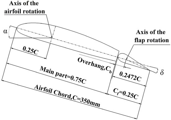
Figure 1.
Main dimensions of the airfoil model with TEF.

Table 1.
Geometry dimensions.
2.2. Control Laws for ECR
Unlike the mode of conventional rotors directly changing the blade pitch through the swashplate, the ECR achieves blade pitch control by generating pitching moment through the flap deflection. This is attained by the control of the flap collective pitch δ0, the flap longitudinal cyclic pitch δ1s, the flap lateral cyclic pitch δ1c, and the flap deflection δ. However, to provide sufficient pitching moment solely through the flap deflection, significant flap deflection is required. Thus, the blade pre-index angle is crucial for pitching control in ECR. According to [30], different blade pre-index angles result in a large difference in flap trim during forward flight. In this study, the blade pre-index angle is 6°, and the motion characteristics of the main part and flap at various advance ratios are considered only for the 1 Ω harmonic component, as described by the following formula:
where α0 is the main part’s average angle of attack (AoA), Δα is the main part’s deflection amplitude, and ω and φα are the main part’s deflection speed and initial phase, respectively.
where δ0 is the flap’s average deflection angle, Δδ is the flap’s deflection amplitude, and φδ is the phase difference between the flap and the main part’s deflection.
According to [30], the pitching motion of the main part and the deflection of the flap were applied in this study. The variations in blade pitch and flap deflection versus azimuth angles for advance ratios μ of 0.1, 0.2, and 0.3 are shown in Figure 2. Since the blade pre-index angle is smaller than the trim requirements for each advance ratio, the flap deflects upwards significantly to generate a nose up moment, increasing the blade pitch. As shown in Figure 2, the blade pitch on the advancing side is smaller than on the retreating side, and the difference between the advancing side and retreating side increases with higher advance ratios. The flap deflection in Figure 2 corresponds to the changes in the main part’s pitching motion. From 0° to 120° azimuth angles, the flap downward deflection generates a nose down moment, decreasing the blade pitch. From 120° to 300° azimuth angles, flap upward deflection generates a nose up moment, increasing the blade pitch.
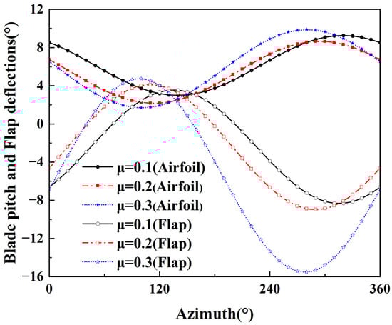
Figure 2.
Motion laws of the main part and flap.
3. The CFD Solver and Grid Geometries
The ECR airfoil with TEF consists of a main part and a flap. To accurately simulate the complex behavior of the flap moving independently while the airfoil is pitching, a sliding grid method, which is advantageous for solving rotating zone problems, is employed to pitch the airfoil at the 1/4 chord length from the airfoil leading edge. This motion is coupled with the motion of the flap by utilizing an overset grid, where interpolation is performed at the airfoil’s trailing edge within the sliding grid’s rotating zone. The coupled flap overset grid pitch around the 1/4 chord length from airfoil leading edge in the rotating zone and simultaneously undergoes independent pitching motion around the axis of rotation of the flap. In terms of the grid, the O-grid technique is applied to the far field, rotating zone, and flap overset grid. The rotating zone extends to 10 chord lengths in all directions, which serves as the background grid for the overset grid. The overset grid extends to four chord lengths in all directions, and the far field boundary extends to forty chord lengths in all directions in order to minimize the effects of numerical reflection. The location of the first row of cells in all grids kept Y+ less than one. Details of medium-resolution grids in three planes are shown in Figure 3.
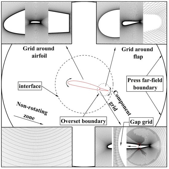
Figure 3.
Grid generation and boundary conditions.
The CFD results are obtained using the CFD flow simulation software ANSYS Fluent 22R1. Since the flow is compressible, a two-dimensional density-based solver was employed in the simulations. The two-equation sst-kω turbulence model, known for its capability to accurately capture near-wall flow separation, is applied for the closure problem. The spatial discretization is achieved by the second-order upwind Flux Difference Splitting (FDS) interpolation within the Roe scheme, and the temporal discretization employs a first-order implicit method. In this study, the time step, dt, is formulated based on the characteristic time of the airfoil, expressed as dt = τ(C/U∞), and it equals 2 × 10⁻⁴ s. The stable calculation results are obtained after five cycles, as verified by requiring that the mean, maximum, and minimum loads changed less than 1% over the ultimate and penultimate cycles. Figure 4 presents the lift coefficient and pitch moment coefficient for the NACA0012 airfoil with a simplified TEF, with the experimental data [15] and CFD computational results [32] for comparison. The airfoil/flap configuration in this study is generated by airfoil data software Profili 2.21. The experimental inflow conditions include a Mach number of 0.4 and a Reynolds number of 1.63 × 10⁶. The rotation axis of the airfoil is located at 35% of the chord length from the airfoil leading edge, while the flap hinge is located at 80%. The pitching motions are as follows:
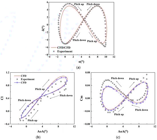
Figure 4.
Comparison of CFD values against experimental value for unsteady aerodynamic force. (a) Airfoil and flap motion in simulation and experiment [32]; (b) lift coefficient [32]; (c) pitch moment coefficient.
A comparison of the simulated and experimental motions of the airfoil and flap is shown in Figure 4a. The lift and moment coefficients generated by the combined airfoil and flap motion are shown in Figure 4b,c, where the calculation results in this paper are compared with the experimental data and calculations in [32]. The results of the calculations in this paper are nearly the same as those in [32], and both show reasonable agreement in unsteady load predictions with the experimental data, and the trends in the lift and moment responses due to unsteady motions of the airfoil and flap are well-captured. The errors in maximum lift and moment coefficients are near 9% and 28%, which might be related to the differences in the airfoil and flap motions between simulation and experiment, as well as the disregard for the three-dimensional effect in the simulation.
4. Analysis of the Aerodynamic Environment of a Helicopter Rotor
The Mach number distribution on the rotor disc plane is shown in Figure 5. The region from the radial section at 0.6 R to 0.8 R is the section with TEF in ECR, where the blade tip Mach number is 0.635, and the advance ratio is 0.3. Figure 5 illustrates that the inflow velocity at the same radial section varies continuously with azimuth angles. The inflow velocity can be described as follows:
where Ma0 is the rotation speed at different sections during blade rotation, Mav is the inflow velocity of the helicopter during forward flight, and θ is the blade’s azimuth angle.
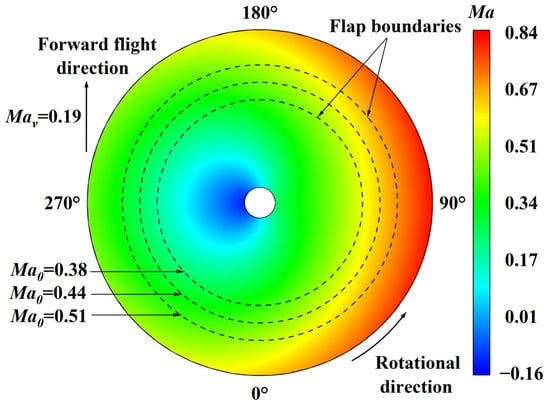
Figure 5.
Mach number distribution on the rotor disc plane.
5. Simulation Result and Analysis
To accurately simulate the aerodynamic characteristics of the ECR airfoil with TEF in forward flight conditions, this paper focuses on the airfoil at the center (0.7 R) of the ECR blades with TEF. This study analyzes the pitching motion of the airfoil under steady and unsteady freestream velocities with an average Mach number of 0.444 at various advance ratios. Both conditions a perform pure pitching motion and the unsteady freestream velocity varies with time. In this section, airfoil and flap motions are based on the sample ECR trim calculation in [30], and only 1 Ω harmonic component is considered in this study. The results presented are organized as follows. First, a grid sensitivity study is conducted on three different grid resolutions. Subsequently, a comparative analysis of the unsteady aerodynamic forces between steady and unsteady freestream velocities at advance ratios of 0.1, 0.2, and 0.3 is conducted.
5.1. Effect of Grid Resolution
To assess the effects of grid resolution, three grids representing level 1 to level 3 of grid resolutions, coarse, medium, and fine, are generated for grid convergence studies. The details of the rotating zone (chordwise direction × normal direction) grids and overset grids (chordwise direction × normal direction) of these grids are summarized in Table 2. A coarse-resolution grid contains 32,000 cells, while the medium grid, obtained by [33], has 68,950 cells, and the fine grid includes 117,200 cells. The sensitivity of CFD simulations to grid resolution is shown in Figure 6. In this figure, the lift, drag, and pitch moment coefficients versus pitching motion are shown for the ECR airfoil pitching motion, where the advance ratio is 0.1 and the Mach number is 0.444, for coarse, medium, and fine grids. The simulations of the unsteady force coefficients for medium and fine grids show great agreement that the mean relative error between the two on a fine grid basis is less than 0.43%, as shown in Figure 6d, which implies low sensitivity to grid resolution for the particular case considered. On the contrary, the mean relative error of the lift coefficient between the coarse and fine grid exceeds 1.2% and the drag coefficient shows significant deviations. Based on this comparison, the medium grids are deemed to be adequate for resolving the flow features and will be used for the results presented in this section.
Table 2.
Computational mesh parameters.
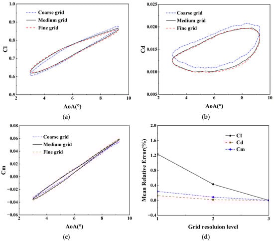
Figure 6.
Comparison of force coefficients with coarse, medium, and fine grids; μ = 0.1, Ma = 0.444. (a) Lift coefficient; (b) drag coefficient; (c) pitch moment coefficient; (d) mean relative error.
5.2. Aerodynamic Characteristics at μ of 0.1
The variations in aerodynamic characteristics of the airfoil with a TEF, with respect to the angle of attack of the main part (at an advance ratio of 0.1), are illustrated in Figure 7. The pitching motion of the main part, the deflection of the flap, and the variation in the freestream velocities are as follows:
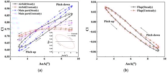
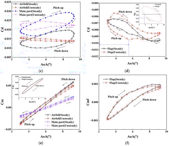
Figure 7.
Aerodynamic characteristics of the airfoil with TEF at μ of 0.1. (a) Lift coefficients of the overall airfoil and the main part; (b) lift coefficient of the flap; (c) drag coefficient of the overall airfoil and the main part; (d) drag coefficient of the flap; (e) pitch moment coefficient; (f) flap hinge moment coefficient.
Figure 7a,b show the lift coefficients of the airfoil, main part, and flap under steady and unsteady freestream velocities, whereas the variations in the steady and unsteady freestream velocities with angles of attack are shown in the inset. In Figure 7a, the main part contributes significantly to the overall lift, and the lift coefficient at unsteady freestream velocity is larger at a small angle of attack due to the larger velocities, while the opposite is observed at a large angle of attack due to the smaller velocities. The decrease in the leading-edge suction pressure coefficient caused by decreased Mach number and the increase in the leading-edge suction pressure coefficient caused by increased Mach number are shown in Figure 8. The effect of compressibility significantly matches the variations in the lift coefficient of the airfoil. With the smooth streamlines and no boundary layer separation and leading-edge vortex shown in Figure 9, the variations in the lift coefficients between both steady and unsteady conditions can be determined to be due to the effects of various velocities and compressibility. With a nearly identical decrease in the lift by the flap, caused by opposing motions between airfoil and flap, a significantly smaller hysteresis loop and stable variation can be observed. A smaller hysteresis loop and stabilizing variations can be observed under unsteady conditions, as the reverse motion results in an almost identical decrease of lift from the flap, which shows little unsteady aerodynamic characteristics.
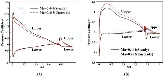
Figure 8.
Pressure coefficient distribution at μ of 0.1. (a) α = 9.26°, δ = −8.31° (pitch down) for Ma = 0.444 (steady) and Ma = 0.415 (unsteady); (b) α = 2.99°, δ = 3.53° (pitch down) for Ma = 0.444 (steady) and Ma = 0.473 (unsteady).
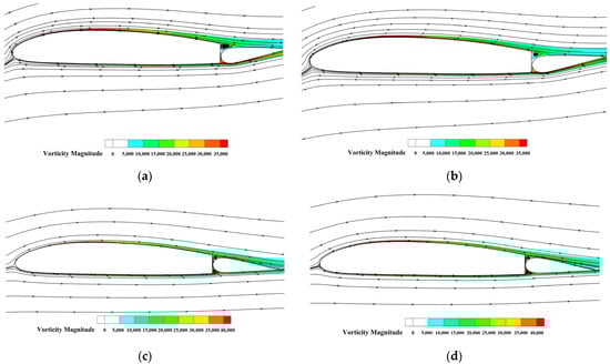
Figure 9.
Vorticity magnitude contour diagrams with instantaneous streamlines at μ of 0.1. (a) α = 9.26°, δ = −8.31° (pitch down) for Ma = 0.444 (steady); (b) α = 9.26°, δ = −8.31° (pitch down) for Ma = 0.415 (unsteady); (c) α = 2.99°, δ = 3.53° (pitch down) for Ma = 0.444 (steady); (d) α = 2.99°, δ = 3.53° (pitch down) for Ma = 0.473 (unsteady).
Figure 7c,d show the drag coefficients of the airfoil, main part, and flap under steady and unsteady freestream velocities, whereas the variations in the steady and unsteady freestream velocities with angles of attack are shown in the inset. The variation in the drag coefficient of the airfoil under unsteady conditions is similar to the lift coefficient, with a slight and stable variation and a small hysteresis loop. As the angle of attack increases, the flap drag coefficient initially decreases and then increases, while the increase is notably slower than the change in velocity, which indicates a significant hysteresis effect on the flap drag coefficient. Due to the influence of the unsteady freestream, the variation of the flap drag coefficient is affected by the hysteresis phenomenon, which provides a larger flap hysteresis loop and shows significant unsteady characteristics.
Figure 7e shows the pitch moment coefficients of the airfoil and main part under steady and unsteady freestream velocities, whereas the flap pitch moment coefficient is shown in the inset. Figure 7 shows the flap hinge moment under steady and unsteady freestream velocities. In these two figures, both the pitch moment and the flap hinge moment coefficients are nearly unaffected by variations in the velocities, exhibiting relatively similar characteristics in both steady and unsteady conditions.
These variations in aerodynamic forces fit well with the changes in characteristics caused by the effect of the compressibility. Therefore, the effect of compressibility needs to be considered under unsteady conditions.
5.3. Aerodynamic Characteristics at μ of 0.2
The variations in aerodynamic characteristics of the airfoil with a TEF, with respect to the angle of attack of the main part (at an advance ratio of 0.2), are shown in Figure 10. The pitching motion of the main part, the deflection of the flap, and the variation in the freestream velocities are as follows:
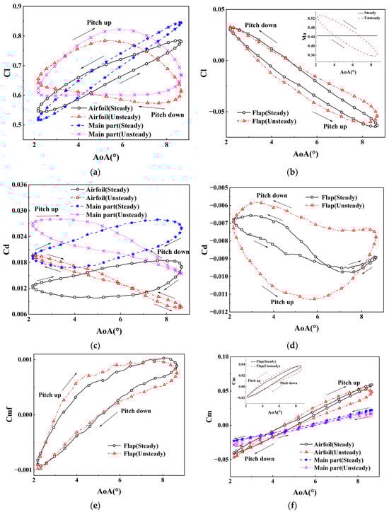
Figure 10.
Aerodynamic characteristics of the airfoil with TEF at μ of 0.2. (a) Lift coefficients of the overall airfoil and the main part; (b) lift coefficient of the flap; (c) drag coefficient of the overall airfoil and the main part; (d) drag coefficient of the flap; (e) pitch moment coefficient; (f) flap hinge moment coefficient.
Figure 11 shows the pressure coefficient distribution on the airfoil for two different Mach numbers. In this figure, the decrease and increase in leading-edge suction pressure coefficient are larger due to the larger variation in unsteady freestream velocities compared to the advance ratio of 0.1. In Figure 11a, a reduced pressure coefficient peak can also be obtained at the lower surface caused by the smaller incoming flow velocity at a large angle of attack, and the reverse can be seen in Figure 11b at a small angle of attack, which suggests that larger velocity variations make the effect of compressibility more pronounced. Figure 12 shows the vorticity magnitude distribution and instantaneous streamlines on the airfoil under steady and unsteady freestream velocities, with no boundary layer separation and leading-edge vortex appearing for little increase in the angle of attack.
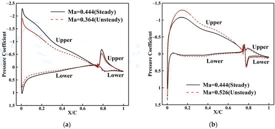
Figure 11.
Pressure coefficient distribution at μ of 0.2. (a) α = 8.65°, δ = −8.96° (pitch down) for Ma = 0.444 (steady) and Ma = 0.364 (unsteady); (b) α = 2.16°, δ = 4.09° (pitch down) for Ma = 0.444 (steady) and Ma = 0.526 (unsteady).
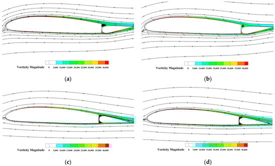
Figure 12.
Vorticity magnitude contour diagrams with instantaneous streamlines at μ of 0.2. (a) α = 8.65°, δ = −8.96° (pitch down) for Ma = 0.444 (steady); (b) α = 8.65°, δ = −8.96° (pitch down) for Ma = 0.364 (unsteady); (c) α = 2.16°, δ = 4.09° (pitch down) for Ma = 0.444 (steady); (d) α = 2.16°, δ = 4.09° (pitch down) for Ma = 0.526 (unsteady).
Figure 10 shows the lift, drag, pitch moment, and flap hinge moment coefficients of the airfoil, main part, and flap, whereas the variations in the steady and unsteady freestream velocities with angles of attack are shown in the inset. In this figure, the lift coefficients appear to be approximately identical to the lift coefficients of the advance ratio of 0.1, while they initially decrease and then increase with the angle of attack at unsteady freestream velocity, caused by more significant effects of the compressibility and hysteresis phenomenon as the variation in the unsteady freestream velocity increases. The lift coefficient hysteresis loop is larger under unsteady conditions, which shows fairly unsteady aerodynamic characteristics. Larger velocity variations lead to a larger hysteresis loop and more variable drag coefficient in the airfoil and flap, which show more unsteady characteristics. The pitch and flap hinge moment coefficients remain in great agreement between steady and unsteady conditions, while a slight increase in hysteresis loop can be observed.
5.4. Aerodynamic Characteristics at μ of 0.3
The variations in aerodynamic characteristics of the airfoil with a TEF, with respect to the angle of attack of the main part (at an advance ratio of 0.3), are shown in Figure 13. The pitching motion of the main part and the deflection of the flap are as follows:
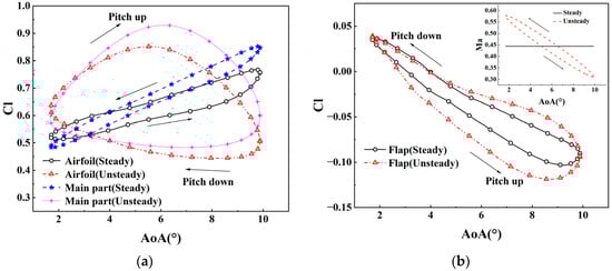
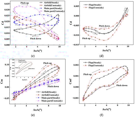
Figure 13.
Aerodynamic characteristics of the airfoil with TEF at μ of 0.3. (a) Lift coefficients of the overall airfoil and the main part; (b) lift coefficient of the flap; (c) drag coefficient of the overall airfoil and the main part; (d) drag coefficient of the flap; (e) pitch moment coefficient; (f) flap hinge moment coefficient.
Figure 14 shows the pressure coefficient distribution on the airfoil for two different Mach numbers. In Figure 14a, the decrease in the leading-edge suction pressure coefficient is very obvious due to the fairly large decrease in velocity at an angle of attack of 9.88° under unsteady conditions, which indicates that the effect of the compressibility is weaker under low-velocity conditions. In Figure 14b, under the increased leading-edge suction pressure coefficient, a significant increased peak and larger lower surface pressure coefficient can be observed at an angle of attack of 1.69° due to the larger velocity and increased effect of compressibility. The velocity distribution at an angle of attack of 1.69° is shown in Figure 15. Figure 16 shows the vorticity magnitude distribution and instantaneous streamlines on the airfoil under steady and unsteady freestream velocities, with some separation of the boundary layer and leading-edge and trailing-edge vortices observed on the flap. In this figure, the flap leading-edge and trailing-edge vortex separation is shown in Figure 16a,c, with a primary recirculating region appearing at an angle of attack of 9.88°. As the velocity is larger, a second recirculating region appears under steady conditions. In Figure 16g, some reversed flow was found at the trailing edge of the flap under unsteady conditions at an angle of attack of 1.69°.
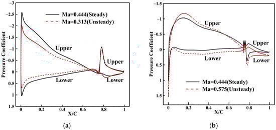
Figure 14.
Pressure coefficient distribution at μ of 0.3. (a) α = 9.88°, δ = −15.52° (pitch down) for Ma = 0.444 (steady) and Ma = 0.313 (unsteady); (b) α = 1.69°, δ = 4.72° (pitch down) for Ma = 0.444 (steady) and Ma = 0.575 (unsteady).
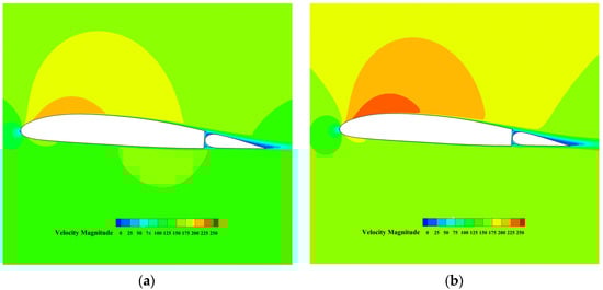
Figure 15.
Velocity magnitude contour diagrams at α = 1.69°, δ = 4.72° for two Mach numbers (pitch down). (a) Ma = 0.444 (steady); (b) Ma = 0.575 (unsteady).
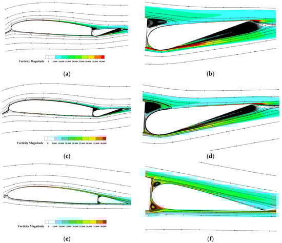
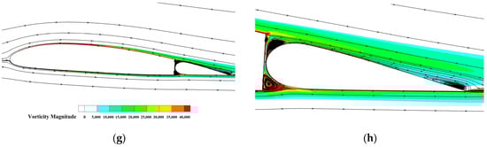
Figure 16.
Vorticity magnitude contour diagrams with instantaneous streamlines at μ of 0.3. (a) α = 9.88°, δ = −15.52° (pitch down) for Ma = 0.444 (steady); (b) detail of flap in (a); (c) α = 9.88°, δ = −15.52° (pitch down) for Ma = 0.313 (unsteady); (d) detail of flap in (c); (e) α = 1.69°, δ = 4.72° (pitch down) for Ma = 0.444 (steady); (f) detail of flap in (e); (g) α = 1.69°, δ = 4.72° (pitch down) for Ma = 0.575 (unsteady); (h) detail of flap in (g).
Figure 13 shows the lift, drag, pitch moment, and flap hinge moment coefficients of the airfoil, main part, and flap, whereas the variations in the steady and unsteady freestream velocities with angles of attack are shown in the inset. In this figure, all of the aerodynamic characteristics show more significant unsteady characteristics due to the larger variations in the freestream velocities, while the pitch moment and flap hinge moment coefficient remain in pretty good agreement under both steady and unsteady conditions. The flap hinge moment coefficient exhibits little fluctuation due to the vortex separation.
6. Conclusions
In this paper, the unsteady aerodynamic characteristics of the airfoil with TEF of a sample ECR are studied using grid, overset grid, and CFD methods. Some meaningful conclusions obtained by comparing the aerodynamic characteristics of the ECR airfoils with TEF under different advance ratios between steady and unsteady freestream conditions are summarized below:
(1) The lift and drag coefficients of the ECR airfoil with flap are significantly affected by unsteady freestream. The lift and drag coefficients are larger at small angles of attack under unsteady freestream conditions due to the variation in the velocity and the effect of the compressibility, while the reverse can be observed at large angles of attack. The effect increases with increasing advance ratios. Both show stable variations and slight unsteady characteristics. As the advance ratios increase, the lift coefficient initially increases and then decreases rapidly with the angle of attack, showing significant hysteresis effects and significant unsteady characteristics caused by unsteady freestream.
(2) The pitch moment and flap hinge moment coefficients of the ECR airfoil with TEF are minimally affected by unsteady freestream. At relatively low advance ratios, they remain almost consistent. As the advance ratios increase, the hysteresis loops of both increase, which shows slight unsteady characteristics. The flap hinge moment coefficient exhibits little fluctuation at large angles of attack due to the vortex separation.
In summary, the lift and drag coefficients of the ECR airfoil with TEF show significant differences between steady and unsteady freestream conditions. The effect of the compressibility increases with increasing advance ratios. The pitch moment and flap hinge moment coefficients are slightly affected by unsteady freestream, which can be approximated using steady freestream in numerical simulations.
Author Contributions
Conceptualization, C.L. and T.S.; methodology, C.L. and H.L.; software, C.L. and H.L.; validation, C.L. and C.A.F.; formal analysis, C.L. and H.L.; investigation, H.L.; resources, K.L. and T.S.; data curation, H.L. and C.A.F. writing—original draft preparation, C.L. and C.A.F.; writing—review and editing, T.S. and K.L. and H.L.; supervision, T.S. and K.L.; funding acquisition, T.S. and K.L. All authors have read and agreed to the published version of the manuscript.
Funding
This research was funded by the Double Thousand Plan Program of Jiangxi Province, (No. jxsq2023101100).
Data Availability Statement
The data that support the study are available from the corresponding author upon reasonable request.
Conflicts of Interest
The authors declare no conflict of interest.
References
- Shen, J.W.; Chopra, I. Swashplateless helicopter rotor with trailing-edge flaps. J. Aircr. 2004, 41, 208–214. [Google Scholar] [CrossRef]
- Mccloud, J.L., III. An analytical study of a multicycle controllable twist rotor. In Proceedings of the Annual National Forum, Washington, DC, USA, 13–15 May 1975. [Google Scholar]
- Lemnios, A.Z.; Dunn, F.K. Theoretical Study of Multicyclic Control of a Controllable Twist Rotor; No. NASA-CR-151959; NASA: Washington, DC, USA, 1976. [Google Scholar]
- Mccloud, J.L., III; Weisbrich, A.L. Wind-tunnel test results of a full-scale multicyclic controllable twist rotor. In Proceedings of the American Helicopter Society, Annual National Forum, Washington, DC, USA, 15–17 May 1978. No. AHS 78-60. [Google Scholar]
- Wei, F.S.; Weisbrich, A.L. Multicyclic Controllable Twist Rotor Data Analysis; No. NASA-CR-152251; NASA: Washington, DC, USA, 1979. [Google Scholar]
- Chopra, I. Status of Application of Smart Structures Technology to Rotorcraft Systems. J. Am. Helicopter Soc. 2000, 45, 228–252. [Google Scholar] [CrossRef]
- Giurgiutiu, V. Review of Smart-Materials Actuation Solutions for Aeroelastic and Vibration Control. J. Intell. Mater. Syst. Struct. 2000, 11, 525–544. [Google Scholar] [CrossRef][Green Version]
- Derham, R. The Aeromechanics of Smart/Active Rotors. In Proceedings of the AHS Aeromechanics Specialists’ Meeting, Atlanta, Georgia, 13–15 November 2000. [Google Scholar]
- Hassan, A.A.; Straub, F.K.; Noonan, K.W. Experimental/numerical evaluation of integral trailing edge flaps for helicopter rotor applications. J. Am. Helicopter Soc. 2005, 50, 3–17. [Google Scholar] [CrossRef]
- Dieterich, O.; Enenkl, B.; Roth, D. Trailing edge flaps for active rotor control aeroelastic characteristics of the ADASYS rotor system. In Proceedings of the American Helicopter Society 62nd Annual Forum Proceedings, Alexandria, VA, USA, 9–11 May 2006; The AHS International, Inc.: Rocklin, CA, USA, 2006. [Google Scholar]
- Roth, D.; Enenkl, B.; Dieterich, O. Active rotor control by flaps for vibration reduction-full scale demonstrator and first flight test results. In Proceedings of the 32nd European Rotor Craft Forum, Maastricht, The Netherlands, 12–14 September 2006. [Google Scholar]
- Rabourdin, A.; Maurich, J.; Dieterich, O. Blue Pulse: Active Rotor Control at Airbus Helicopters—New EC145 Demonstrator and Flight Test Results. In Proceedings of the American Helicopter Society 70th Annual Forum Proceedings, Alex-Alexandria, VA, USA, 27–29 May 2009; The AHS International, Inc.: Rocklin, CA, USA, 2009. [Google Scholar]
- Leishman, J.G. Principles of Helicopter Aerodynamics; Cambridge University Press: Cambridge, UK, 2006. [Google Scholar]
- Conlisk, A.T. Modern helicopter aerodynamics. Annu. Rev. Fluid Mech. 1997, 29, 515–567. [Google Scholar] [CrossRef]
- Krzysiak, A.; Narkiewicz, J. Aerodynamic Loads on Airfoil with Trailing-Edge Flap Pitching with Different Frequencies. J. Aircr. 2006, 43, 407–418. [Google Scholar] [CrossRef]
- Lee, T.; Su, Y.Y. Unsteady airfoil with a harmonically deflected trailing-edge flap. J. Fluids Struct. 2011, 27, 1411–1424. [Google Scholar] [CrossRef]
- He, G.S.; Deparday, J. Stall Delay and Leading-Edge Suction for a Pitching Airfoil with Trailing-Edge Flap. AIAA J. 2020, 58, 5146–5155. [Google Scholar] [CrossRef]
- Pohl, J.; Semaan, R.; Jones, A.R. Dynamic Lift Measurements on an Airfoil with Periodic Flap Motion at High Reynolds Number. In Proceedings of the AIAA Scitech 2019 Forum, San Diego, CA, USA, 7–11 January 2019. AIAA Paper 2019-1396. [Google Scholar]
- Shen, J.; Chopra, I. Aeroelastic Stability of Trailing-Edge Flap Helicopter Rotors. J. Am. Helicopter Soc. 2003, 48, 236–243. [Google Scholar] [CrossRef]
- Straub, F.K.; Charles, B.D. Aeroelastic analysis of rotors with trailing edge flaps using comprehensive codes. J. Am. Helicopter Soc. 2001, 46, 192–199. [Google Scholar] [CrossRef]
- Mishra, A.; Sitaraman, J.; Baeder, J. Computational investigation of trailing edge flap for control of vibration. In Proceedings of the 25th AIAA Applied Aerodynamics Conference, Miami, FL, USA, 25–28 June 2007; p. 4290. [Google Scholar]
- Gerontakos, P.; Lee, T. Dynamic stall flow control via a trailing-edge flap. AIAA J. 2006, 44, 469–480. [Google Scholar] [CrossRef]
- Gharali, K.; Johnson, D.A. Dynamic stall simulation of a pitching airfoil under unsteady freestream velocity. J. Fluids Struct. 2013, 42, 228–244. [Google Scholar] [CrossRef]
- Xing, S.L.; Xu, H.Y. Trailing Edge Flap Effects on Dynamic Stall Vortex and Unsteady Aerodynamic Forces on a Pitching Airfoil, International Journal of Aerospace Engineering. Int. J. Aerosp. Eng. 2022, 2022, 20. [Google Scholar]
- Su, T.Y. A Fuzzy Logic/CFD Combined Approach for Modeling the Unsteady Aerodynamics of an Airfoil with Trailing Edge Flap. J. Nanchang Hangkong Univ. 2022, 36, 14–21. [Google Scholar] [CrossRef]
- Wang, Q.; Zhao, Q.J. Unsteady aerodynamic characteristic analysis of rotor airfoil under variational free stream velocity condition. Hangkong Dongli Xuebao/J. Aerosp. Power 2017, 32, 364–372. [Google Scholar] [CrossRef]
- Pierce, G.A.; Kunz, D.L. The effect of varying freestream velocity on dynamic stall characteristics. In Proceedings of the 32nd Annual National Forum of the American Helicopter Society, Washington, DC, USA, 21 May 1976; NASA: Washington, DC, USA, 1976. [Google Scholar]
- Visbal, M.R.; Shang, J.S. Investigation of the flow structure around a rapidly pitching airfoil. AIAA J. 1989, 27, 1044–1051. [Google Scholar] [CrossRef]
- Leishman, J.G.; Beddoes, T.S. A semi-empirical model for dynamic stall. J. Am. Helicopter Soc. 1989, 34, 3–17. [Google Scholar]
- Su, T.Y.; Lu, Y. Aerodynamic characteristics analysis of electrically controlled rotor based on viscous vortex particle method. Aerosp. Sci. Technol. 2019, 97, 105645. [Google Scholar] [CrossRef]
- Lu, Y.; Wang, H.W. Paramenter Study of the Airfoil with Flap Used for Electrical Controlled Rotor. Helicopter Tech. 2004, 3, 18–22. [Google Scholar] [CrossRef]
- Wang, J.; Yang, M. CFD Simulation of Unsteady Aerodynamics of Airfoil with Trailing-Edge Flap. Comput. Simul. 2011, 28, 88–92. [Google Scholar] [CrossRef]
- Liu, L.; Padthe, A.; Friedmann, P.; Quon, E.; Smith, M.J. Unsteady aerodynamics of an airfoil/flap combination on a helicopter rotor using computational fluid dynamics and approximate methods. J. Am. Helicopter Soc. 2011, 56, 1–13. [Google Scholar] [CrossRef]


Disclaimer/Publisher’s Note: The statements, opinions and data contained in all publications are solely those of the individual author(s) and contributor(s) and not of MDPI and/or the editor(s). MDPI and/or the editor(s) disclaim responsibility for any injury to people or property resulting from any ideas, methods, instructions or products referred to in the content. |
© 2023 by the authors. Licensee MDPI, Basel, Switzerland. This article is an open access article distributed under the terms and conditions of the Creative Commons Attribution (CC BY) license (https://creativecommons.org/licenses/by/4.0/).