Article

Robust Flight Tether for In-Orbit Demonstrations of Coulomb Drag Propulsion

Finnish Meteorological Institute, Erik Palménin Aukio 1, 00560 Helsinki, Finland
*
Author to whom correspondence should be addressed.
Aerospace 2024, 11(1), 62; https://doi.org/10.3390/aerospace11010062
Submission received: 6 November 2023 / Revised: 23 December 2023 / Accepted: 24 December 2023 / Published: 9 January 2024
(This article belongs to the Special Issue Advances in CubeSat Sails and Tethers)

Abstract

:
A new method of producing robust multi-wire tethers for Coulomb drag applications was developed. The multi-wire structure required for redundancy against the micrometeoroid flux of the space environment is realised through the method of wire twist bonding traditionally used for chicken wire. In the case of the Coulomb drag tether, the diameter of the individual wires is 50 μm, which introduces the main technological challenge. To manufacture the tether, a manually driven tether machine was designed and built. Two multi-wire tethers for Coulomb drag applications were produced for two in-orbit demonstrations of the FORESAIL-1 and ESTCube-2 CubeSat missions. The flight tethers were both 60 m long as produced, clearly demonstrating beyond the level of proof of concept the applicability of both the method and the manually driven tether machine. Altogether, 6480 twist bonds were produced without a single wire cut. In this paper, the requirements for the tether are listed and justified. The production method is reviewed, and the 4-wire tether produced is evaluated against the requirements. Finally, the test procedures of the tether are described, and on the basis of the results, it is concluded that the tether can tolerate a tension of 14 g without the twist bonds slipping or the tether structure collectively collapsing. Furthermore, the tether can be reeled from the production reel to the flight reel, which simplifies the final integration of the tether reeling system with the Coulomb drag propulsion device.

1. Introduction

1.1. Coulomb Drag and Propulsion

Coulomb drag is predicted to generate a drag force when an electrically charged object is situated in a space plasma flow [1]. At its simplest, the object can be an electrically conducting wire. The electric field of the wire distorts the flowing charged particles, and a drag force is generated similarly to the air flow around an obstacle in the neutral atmosphere. Note that both polarities distort the plasma flow and cause drag [2,3]. As the electric field is the obstacle, its effective cross-section is much larger than the physical dimensions of the wire itself. In practice, due to the space environment micrometeoroid flux, a single wire would be destroyed in matters of days or weeks, and a multi-wire tether that has a designed degree of redundancy against the micrometeoroid hits has to be used for the required mission life times.
In the space plasma, plasma particles tend to neutralise the charge state of the wire by the ions or electrons depending on the wire polarity. This implies that the charge state has to be actively maintained. An electrical power system is required to run the electrical current system between the wire, the space plasma, and the power system. The magnitude of the current depends on the surface area of the wire. The thinner the wire, the less current is generated, the less power is required, and the lighter the power system is. Thus, the tether should be manufactured using wires as thin as possible. Such a tether is the key component for Coulomb drag propulsion.
Coulomb drag physics and propulsion are different from that of electrodynamic tethers (see, for example, [4]) that rely on the Lorentz force, i.e., tether electric current and external magnetic field. Most importantly, this implies that in a low-Earth orbit, the Earth’s magnetic field causes negligible torque to the Coulomb drag tether. Furthermore, the Coulomb drag tether can be used as a source for spacecraft propulsion in the solar wind where the magnetic field is weak. In the former case, the Coulomb drag can be used to decrease the orbital speed of the satellite as a plasma brake [5]. In the latter case, it can be harnessed to generate a continuous low thrust for a spacecraft equipped with an electric solar wind sail [6].

1.2. Electric Solar Wind Sail

An electric solar wind sail provides a spacecraft with a continuous low thrust arising from the Coulomb drag in the solar wind flow [6]. The tethers of the sail are kept stretched by the centrifugal force, implying a slowly rotating spin-stabilised flight configuration—a multi-tether sail looks like a starfish. With a reasonable spacecraft mass, a characteristic acceleration of 1 mm/s 2 can be achieved at 1 au for the typical solar wind parameters, i.e., plasma number density and solar wind speed. As a rule of thumb, this translates to a delta-v of 6.6 au/year when the spacecraft is accelerated continuously for 1 year. The characteristic acceleration scales in solar distance r as 1/r [7]. It should also be noted that the thrust can be turned off by simply switching off the tether voltage. This is a remarkable feature for the proximity manoeuvres and coasting phases expected for optimal planetary transfer orbits [8]. By modulating the tether voltages synchronistically with the sail rotation, the sail attitude with respect to the sun can be controlled [9,10]. There are several mission analyses that have been performed based on E-sail propulsion: non-Keplerian orbits [11]; electric sail mission analysis for outer solar system exploration [12]; electric sail missions to potentially hazardous asteroids [13]; moving an asteroid with an electric solar wind sail [14]; electric sail for a near-Earth asteroid sample return mission for the case of 1998 KY26 [15]; electric sailing for cometary rendezvous [16]; and nanospacecraft fleets for multi-asteroid touring with electric solar wind sails [17].
In the case of the electric solar wind sail, a positive voltage is applied to the tether [2]. To maintain the tether voltage, an electron emitter is required to run the current system arising from the electron current gathered by the positive tether. The current loop is closed through the power system, the emitter, and the space plasma. This implies that decreasing the tether wire thickness reduces the power system mass, including the solar panels, for efficient characteristic acceleration.

1.3. Plasma Brake

A plasma brake was suggested as a candidate for space debris mitigation by [5]. A plasma brake assumes a negatively biased tether. In principle, the negative tether gathers an ion current from the ionospheric plasma that would imply an ion emitter in the system. However, the ion emitter can be avoided for two reasons: One is that the ion current is smaller than the corresponding electron current by a factor of 43 (the square root of the proton-to-electron mass ratio). The other is that the ionospheric electron number density is large enough to “ground” an electron collecting conducting surface to the ambient plasma potential. Thus, only a high-voltage converter system is required to maintain a high-voltage difference, typically, 1 kV between the tether and the potential of the conducting surface. As the life time of high-voltage converters is much longer than that of ion or electron emitters, the plasma brake can be considered as a passive deorbiting system. Again, the spatial size of the conducting surface area and the high-voltage system mass is dictated by the tether wire diameter through the ion current collected.
Recently, an extensive feasibility study on the plasma brake was carried out as an ESA CleanSat project [18]. It was concluded that the device module designed in the study was lightweight (2 kg), low-cost (50 k€ recurrent), and that it could deorbit a 400 kg satellite from 850 km or a 100 kg satellite from 1200 km in about 6 years. Here, it is assumed that the tether is gravity-gradient-stabilised. Thus, two tethers elongated radially downward and upward can be used, and the masses double to 800 kg and 200 kg, respectively.

1.4. In-Orbit Demonstrations with CubeSats

Presently, there are three collaborative efforts underway to demonstrate the Coulomb drag physics and propulsion, involving LEO, FORESAIL (Finnish Academy, Center of Excellence in Sustainable Space), ESTCube (Estonian Student Satellite Foundation), and Aurora Propulsion Technologies (Finnish startup company). Under the FORESAIL consortium, a FORESAIL-1p satellite is being built to be launched in spring 2024. This is a next iteration of FORESAIL-1 [19] that failed due to loss of communication. ESTCube-2 was launched in October, 2023 [19]. Prior to these efforts, there had been two Cubesats: ESTCube-1 [20] and Aalto-1 (Student satellite of Aalto University) [21]. While these satellites were a success, failures in the tether deployment mechanics or electronics led to unsuccessful tether deployments and precluded further testing of Coulomb drag in LEO [22,23]. However, these efforts have greatly contributed to the further development of the micro-tether and its deployment system.

1.5. Tether Geometries and Bonding Methods

The geometry of a micrometeoroid-resistant multi-wire tether can basically be freely designed to meet the tether lifetime requirements. However, tether manufacturing, i.e., bonding methods, and the deployment of the tether in space exclude the most exotic geometries. Prior to the present work, there have been three related efforts as reviewed below.
A variety of practical geometries for the space tethers have been suggested and patented [24]. Considering the applications in Coulomb drag propulsion, tether types that have wires parallel along with the tether and wires zigzagging between the parallel wires are selected for the present tether manufacturing process.
A wire-to-wire ultrasonic bonding method has been used to produce a Coulomb drag tether [25]. The bonding method dictated the tether geometry. It consisted of a base wire and loop wires, and the wire material was aluminium. Due to the material selection, the oxygen layer of the aluminium had to be removed by ultrasound to achieve the natural cold welding condition of aluminium. The base wire was thicker than the loop wires that were bonded to the base wire, as shown in Figure 1. The diameter of the base wire was 50 μm and that of the three loop wires was 25 µm. ESTCube-1 accommodated a 10 m tether while Aalto-1 already used a tether of 100 m. Furthermore, a single space tether with a length of one kilometre was later produced as a proof of concept [26]. While the production process turned out to be a success, some issues remained. These arose from the requirements for the ultrasonic bonding of thin wires and related requirements concerning the cleanliness of the bonding heads, the accuracy of the wire placements with respect to each other, and to the bonding heads.
Following the ultrasonic bonding method, metals with no oxide layer or a layer that could more easily be removed than that of aluminium were considered. Naturally, noble metals, such as gold, have no oxygen layer. Furthermore, the oxygen layer of silver can be removed by heating the wire to about 300 °C. Thus, the cold welding of these materials was selected as a bonding method which would be more robust than ultrasonic welding. Using gold and silver, this method was successfully tested for the production of short tether samples [28]. However, the tether produced had a geometry of a ladder, and the perpendicular wires (rungs) of the tether overlapped the parallel wires (side rails), leaving the tether with whiskers that could lead to problems with tether deployment. This issue could have been avoided by better design of the tether machine. However, silver wire is extremely prone to the atomic oxygen in LEO and gold is expensive and heavy. For these reasons, cold welding was not developed further for LEO missions. For missions in the solar wind, silver and cold welding may still be reconsidered in the future.
An old and robust method of producing a bond between two metal wires is twisting. This method has been used for producing chicken wire used in several applications from fencing poultry to fishing. As the machines producing chicken wire are extremely robust, this method was selected as a candidate for Coulomb drag tether production. The wires used for the chicken wire are typically from about 1 mm up to several mm. Concerning the chicken wire geometry, the tether geometries described by Hoyt [24] were the natural choice. The scaling of the existing chicken wire machines to the Coulomb drag tether and the wire dimensions introduced the major challenge. In terms of the wire tensile strength, the wire thicknesses introduced a factor of 400 (50 µm), at minimum. In addition to the scaling, the geometry of the traditional machine also had to be modified for thin wires. How these challenges were overcome and the development of the chicken wire Coulomb drag tether machine is described in this work.

2. Tether Manufacturing

2.1. Wire Twisting

When using wire twisting to make the bond between two wires, there are several key requirements for a robust bond. Initially, there are two wires clamped as shown in Figure 2a. One of the clamps (pink) is unyielding, while the other (cyan) feeds the wires under a defined yielding strength. The first requirement is that the twist has to be symmetric, i.e., the bonding head rotation axis has to be centred between the wires to be twisted (Figure 2b). This ensures that both wires will undergo an identical plastic deformation (Figure 2c). If the initial setup is not symmetric and, for example, the rotation axis is aligned with one of the wires, only the other wire will be deformed, and a slipping bond can be expected. Secondly, the number of twists has to be adjusted so that the wire tension remains below the wire material tensile strength. To prevent the wires from cutting, the yielding strength of the wire dispensers is tuned to define the pull strength of the bond. This parameter couples the twist pull strength to the bonding and tether production reliability with a statistical margin to avoid undesired wire cuts.

2.2. Bonding Process in General

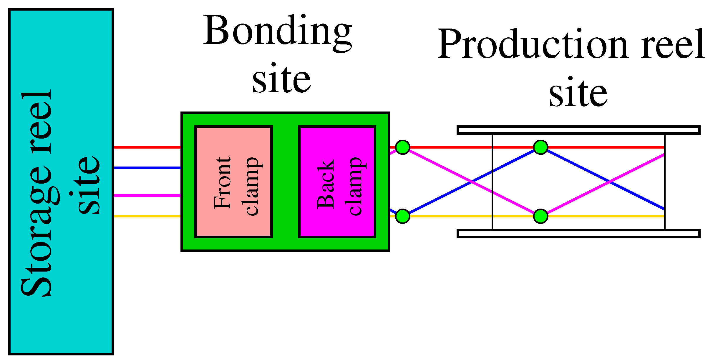
The main components of the tether bonding process are a set of wire storage reels, wire dispensers, a bonding system, and a production reel (Figure 3). Presently, five storage reels can be utilised. The bonding system is such that it has three bonding heads each, as depicted in Figure 2. Furthermore, there are two clamps at the bonding site. One ensures the wire positions during the wire twisting. The other maintains the tether width while the storage reel locations are interchanged according to the tether geometry. In Figure 3, there are four storage reels and three twisting sites employed to bond two wire pairs together (green blobs). The tether is then reeled to a production reel, bond pair by bond pair. After the storage reel interchange, the time used for twisting, clamping, and production reel operation is independent of the tether geometry. The interchange introduces no significant time differences among the geometries relative to the rest of the bonding sequence.

2.3. Tether Geometries

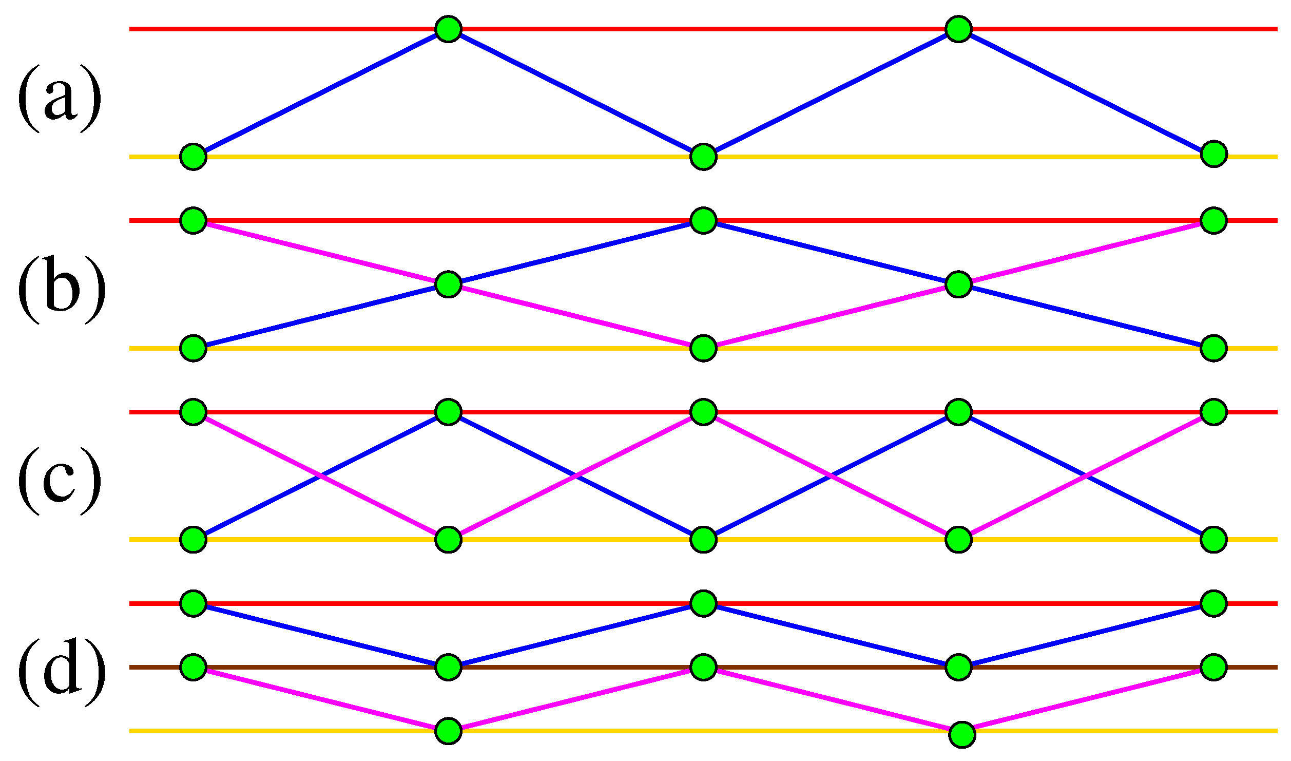
Using the present tether machine, four types of tethers can be produced, as depicted in Figure 4. The distance between the bonds along the tether is fixed by the selected distance between the front and back clamps. It is also possible to freely alternate the wire positions from being parallel to zigzagging along the tether in the manufacturing process. Presently, we have not mixed the parallel wires and zigzagging wires, implying that an intact tether can tolerate the tension of the parallel wire tensile strength instead of the twists without collapsing. This can be utilised during the early deployment of the tether for increased pull strength.

3. Requirements and Implications

The general physical and practical requirements arise from the space environment, the Coulomb drag payload integration and operations, and the tether manufacture. These include drivers for the tether and tether machine requirements, as summarised in Table 1. Some of the requirements were added with hindsight. Furthermore, expected future steps are also considered. Further clarifications, reasoning, and relevant issues are described in the subsections below, as indicated in Table 1.

3.1. Space Environment

3.1.1. Redundancy for Micrometeoroids

The most crucial requirement for the Coulomb drag tether is the micrometeoroid resistance. A single wire lifetime in the space environment micrometeoroid flux is short compared to any useful mission timescale. The lifetime can be extended by adding redundant wires to form a multi-wire tether. In addition to the number of wires, the tether width can be used as a free parameter to design the tether lifetime for the expected micrometeoroid environment. The tether width can be optimised based on space environment micrometeroid flux models, such as MASTER 2009 [29]. An example of such an analysis is provided for the LEO environment for the plasma brake application of the Coulomb drag propulsion in [18]. Here, however, the width of the 4-wire tether (1.5 cm) is selected to comply with the CubeSat payload dimensions. Furthermore, any tendency of the tether to become 3-dimensional after the deployment extends the lifetime since a purely 2-dimensional tether can be cut by a single collision occurring in the tether plane. The tether width dictates the length scale of the bonding site of the tether machine.

3.2. Coulomb Drag Payload Integration and Flight Operations

3.2.1. Payload Integration

The option of moving a ready-made tether from the production reel to the flight reel is practical in many ways. The tether production is independent of the flight model payload integration as several flight tethers can be manufactured by using production reels specific to the tether machine. Thus, the machine does not need to be modified for various flight tether types as the rewinding system can take into account the flight tether details. This also provides the timeline of the integration process with some flexibility. It improves the reliability of the integration. Also, no delicate flight reels are not on hold while attached to the tether machine. Finally, an important aspect of the reel-to-reel option is that the flight tether can be carefully inspected while rewound and careful packing of the flight tether to the flight reel can be ensured. Furthermore, any single wire cuts can be made harmless by cutting the loose wire ends next to the bond.

3.2.2. Deployment and Flight Dynamics

The tether deployment may be prone to single wire cuts and partially reversed overlapping between the tether layers on the reel. Should there be any wire cuts in the flight tether identified during the rewinding process, the tether can be disqualified or the loose wire can be cut next to the bond to minimise the risk of deployment failures. The effect of the cut wire on the reliability of the whole tether lifetime can be neglected. Concerning the deployment, the failures are strongly functions of the centrifugal force or, in general, the pull force available for the deployment.
Concerning the tether flight dynamics after the deployment, it can be expected that serpentine-type curliness of the tether may cause potentially harmful random global oscillations of the effective length of the tether. Determining the spring constant of such a long structure is not trivial, and the production and the flight reels should have sufficient curvature radii to avoid such anomalous spring constants. The wire diameter, together with the wire material, dictates the minimum bending curvature radius that will cause no plastic deformation to the wire. This sets the limits for the wire guiding and the spatial scale of the bonding site.

3.2.3. Electrical Power Consumption

The magnitude of the electrical current gathered by the charged tether is dictated by its surface area. Thus, the thinner the tether wire is, the smaller the electric current magnitude is for a given tether length, geometry, and number of multiple wires. Thus, the wire diameter becomes the main mass driver through the electrical power system, including solar panels adequate to run the required current, although the tether mass itself is negligible.

3.3. Tether Manufacturing

3.3.1. Manual Mode

The present tether machine was developed for manual use. Currently, the production speed is 1 m of tether in 15 min. The production speed is basically independent of the tether geometry, as addressed in Section 2.2. The production speed limited the length and number of the tether samples, but enabled the production of the two flight tethers of FORESAIL-1 and ESTCube-2. When the manual machine was designed, automation was also a key design driver. Thus, the manual machine also serves well as a development version towards a fully automated machine. This means that the designated mechanical parts, the actuators, and the software can be embedded into the manual machine through intermediate steps, while the functionality can be certified after each step by adequate testing and debugging.

3.3.2. Tether Machine Parameters for Calibration

The present tether machine has several free parameters that can be tuned to determine the twist bond strength and to calibrate the machine. The key parameters are described in Table 2. As described in Section 4.3, these parameters are necessary and adequate for the smooth operation of the machine and reliable tether production.

4. Results: Tether Type Selection, Testing, and Production

4.1. Tether Type Selection

For the production, a 4-wire tether of the second kind (Figure 4c) was selected: the wires zigzagging between the parallel wires are not bonded together in the middle of the tether. The resulting tether is shown in Figure 5. The selection was based mainly on three notions: (1) the angle between the parallel and zigzagging wire is the largest; (2) the bonding sequence is the simplest and fastest for the manual mode; and (3) this tether configuration may well be the most 3-dimensional when deployed in space while it is still packing well to the tether reel.
The spatial dimensions of the selected tether are the following: The bond distance is 3.75 cm (distance between the machine front and back clamps), and the tether width is about 1.5 cm. These numbers correspond to an angle of about 22 degrees between the parallel and zigzagging wires. These numbers are determined as averages over several longer tether samples. Note that the sample shown in Figure 5 is not under tension, and the tether dimensions are somewhat misleading. The single aluminium wire thickness was selected to be 50 µm. This diameter corresponds to a tensile strength of 49 g.

4.2. Testing of the Produced Tether

Tests were planned to meet the ESTCube-2 and FORESAIL-1 mission requirements and to take into account the limited number of test samples that could viably be produced by the manually operated tether machine. The testing can be divided into four categories: (1) destructive tests; (2) production tests; (3) vibration tests; and (4) deployment pull-strength tests. These tests are described in detail in the subsections below. The test philosophy was the following: The destructive tests of a set of tether samples were executed to determine the maximum pull strength of both the single twist bond and the entire tether. Then a new set of tether samples were produced, and tether quality, mainly the tether width, was visually inspected during the manufacturing process. After testing these new samples, it was concluded that when the tether remained satisfactory visually during the process, the pull-strength values were satisfied.

4.2.1. Destructive Tests

The single twist bond strength was tested by having a test tether sample hang loosely against a piece of black cardboard for good visibility. The bonds were selected one-by-one, fastened to the cardboard by Kapton tape, and cut free from the tether, as shown in Figure 6 (left). A test mass of 15 g was clamped under the bond (red disk). The test was successful if the addressed bond held, i.e., the twist did not curl open.
To test the tether structural strength as a whole, a test mass of 15 g was attached to a tether specimen, as shown in Figure 6 (middle). The test was successful if the tether sample could stand the test mass without the twist bonds collectively loosening, causing the entire tether sample to collapse.
As the third destructive test, a tether sample was hung under a tension of 15 g. Single tether wires were then cut one-by-one, here and there, along the tether to replicate the micrometeoroid cuts (Figure 6 (right)). The overall tether shape was monitored after each cut, and the test was deemed successful if the tether collapsed to a one-dimensional bunch of wires locally only. Note that the flop down shock induced by these wire cuts is not as harsh in space as in the test.

4.2.2. Tether Production Tests

As the tests of quality were mainly destructive, they cannot be used during the tether production process. It was noted that if the tether twist bonds started slipping during the tether production, the width of the tether started to significantly decrease during a few bonding sequences. This was consistent with the fact that the tether did not withstand the test mass of 15 g without collapsing. On the other hand, when the tether width remained constant during the production, the test mass experiments were successful. Thus, a visual inspection of the tether width during the tether production implied that the tether quality could be considered adequate for large scale tether production.

4.2.3. Vibration Test

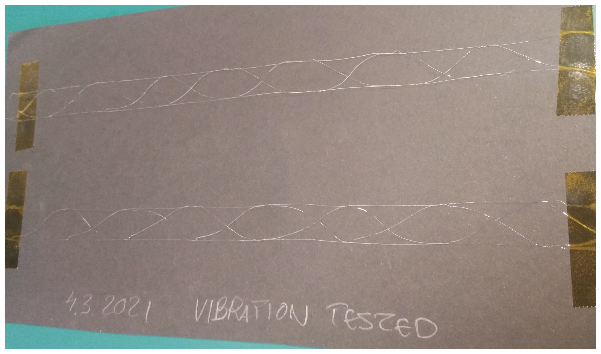
During the development of FORESAIL-1 and ESTCube-2, the Coulomb drag payload was normally vibration tested. The qualification level model had 30 m of tether on the reel. After successful vibration tests, the tether was reeled out for visual inspection (Figure 7), destructive tests (Section 4.2.1), and deployment pull-strength tests (Section 4.2.4).

4.2.4. Deployment Pull-Strength Tests

As the final test, the pull force required for the tether deployment was tested using the deployment mechanism designed for FORESAIL-1 and ESTCube-2. This was performed using both virgin and vibrated tethers. No difference between these test samples was observed, which is in accordance with the visual inspection of the vibrated tether with no damage identified. The experiment was realised by deploying the tether with various test masses attached to the tether. It was concluded that the deployment was reliable when the pull force was more than 0.1 g.

4.3. Production Reliability

The present level of the production reliability of the tether type and the tether machine is the following: Two pieces of flight tethers, both 60 m long, were produced for two Cubesat test missions, FORESAIL-1 and ESTCube-2. Altogether, this corresponds to 6480 bonds. Figure 8 shows the flight tether of FORESAIL-1 on the production reel. During the manufacturing process of these two flight tethers, no single wire cuts occurred. Furthermore, the tether width remained constant throughout the process for the required quality of the flight tether, as described in Section 3. In the case of a single wire cut, the production can be recovered. A wire cut event is only fatal when two wires are simultaneously cut. However, according to the number of successful bonds of 6480, the success rate of nonfatal wire cuts was proportional to 6480.

4.4. Payload Integration

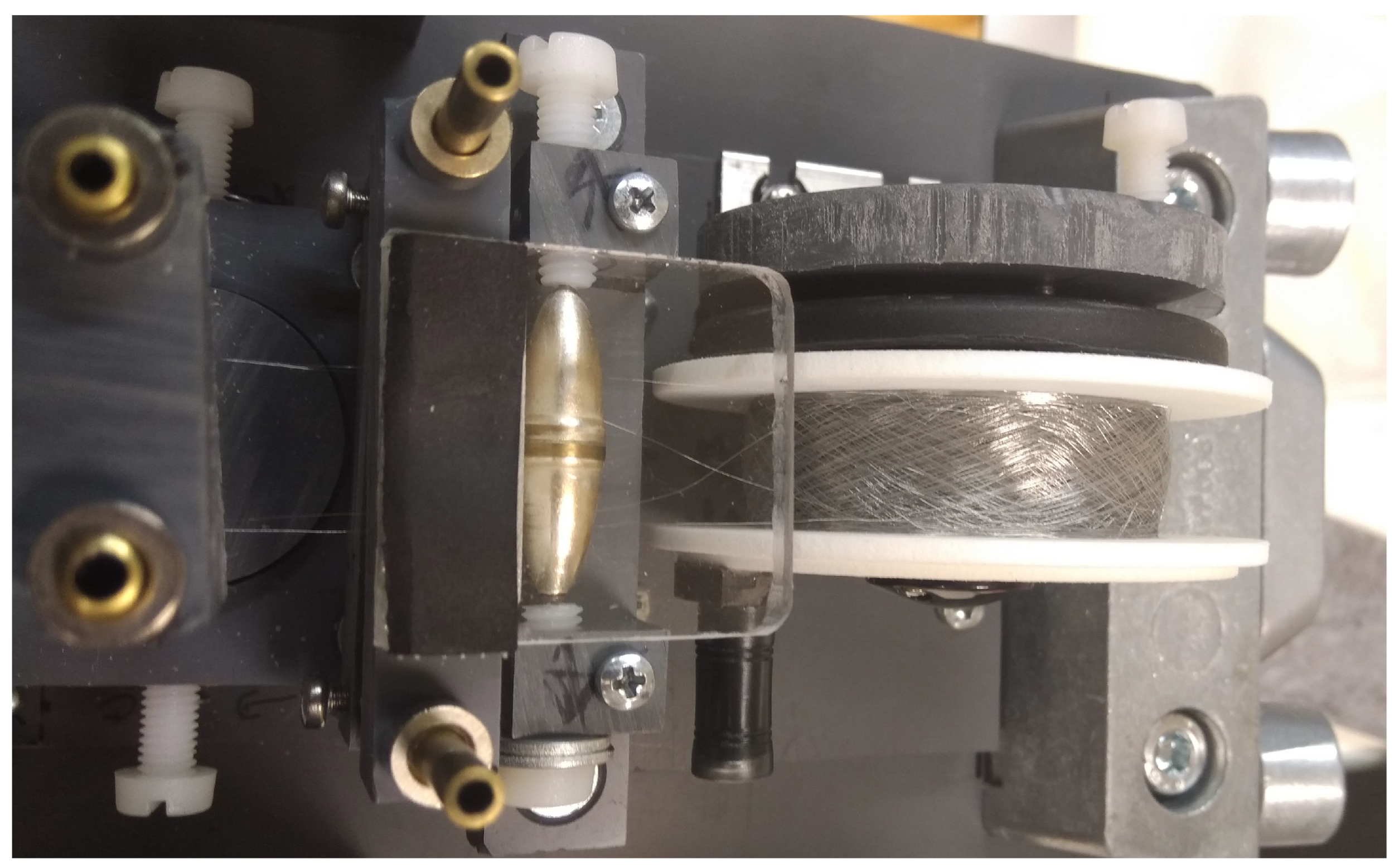
The Coulomb drag payload integration starts with rewinding the flight tether from the production reel to the flight reel, as shown in Figure 9. There is a roller guide that maintains the distance between the tether parallel wires during the process. After the entire tether is on the flight reel, a Kapton foil is attached to the tether and wound on the top of the tether layers. The foil serves as a protective cover but, more importantly, it is further used during the payload integration.
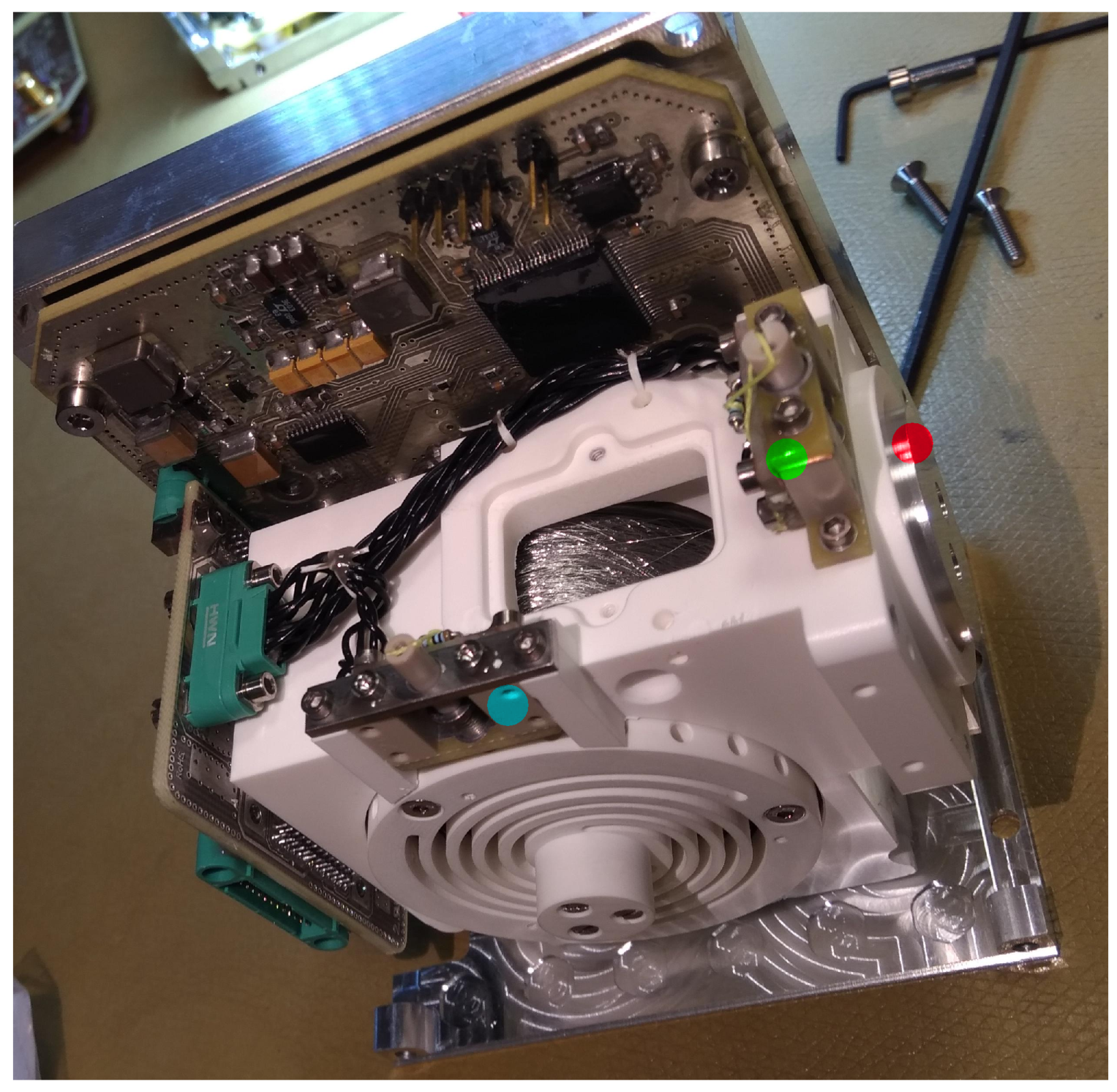
Figure 10 shows the tether as integrated in the Coulomb drag experiment onboard ESTCube-2. After the deployment mechanism (stepper motor and the reel) has been integrated, the foil is used to pull the tether end from the reel throughout the end mass opening. The end mass (red dot in Figure 10) is attached to the tether and reeled back to its position in the end mass opening. The end mass launch locks (green dot in Figure 10) and the reel lock (cyan dot in Figure 10) is fastened.

4.5. Interfaces between Spacecraft

The Coulomb drag experiment was designed to be a plug-and-play payload for easy integration with the spacecraft frame and the electrical systems. It is a self-contained box fitting neatly inside one CubeSat unit.

4.5.1. Mechanical Interface

Figure 11 shows the mechanical interface of the FORESAIL-1 Coulomb drag experiment as an example. The payload is attached to the CubeSat frame using eight M3-screws. In addition, there is an outlet for the end mass and tether through a side panel of the satellite. As the ESTCube-2 had a pair of electron emitters, another outlet for them was required through another side panel.

4.5.2. Electrical Interface

FORESAIL-1 has two electrical interface connectors. One is a pigtail Glenair connector connecting the payload to the CubeSat onboard computer and the electrical power system, as shown in Figure 12 with the connector pin out. The pins include the following: GND: 0 V; BATT: nominally 7.5 V DC; 3V6: 3.6 V DC; PRI_DATA+/−: RS485 serial data differential pair; and SEC_DATA+/−: RS485 serial data differential pair (redundant). The data include the tether voltage, the tether current, the launch lock diagnostics, and several temperature readings, most notably those of the stepper motor and its driver electronics. There is some degree of freedom in selecting the connector and pin out as the selected connector is a pigtail. The other connector is an SMA connector that connects the HV system and the tether to the conducting surface, as described in Section 1.3. In the case of FORESAIL-1, the conducting surface is realized by four deployable rods. ESTCube-2 has deployable solar panel wings with conducting frames to close the tether current system through the space plasma.

5. Conclusions

5.1. Summary

Two 4-wire tethers for two CubeSat missions of FORESAIL-1 and ESTCube-2 were manufactured using a newly developed manually operated tether machine. The bonding of the wires to each other results in redundancy against the micrometeoroid environment in space. The bonding is based on plastic deformation by twisting of the wire pairs similarly to chicken wire. The aluminium wire used has a thickness of 50 µm. The two flight tethers were 60 m long as produced, including altogether 6480 twist bonds. During the bonding process, no single wire cuts occurred, which implies that the twisting method and the machine is robust. Furthermore, the production process can be recovered after a single wire cut, only a double wire cut is fatal for the tether, and, thus, the success rate of nonfatal wire cuts is proportional to 6480. We note here that during the review process of this paper, the flight tether of FORESAIL-1p was produced successfully, which increases the number of successful bonds to 9720.
In this paper, we walked the reader through the whole process of producing a tether, starting from the requirements arising from the Coulomb drag physics and the space environment, to production, testing, and integration of the tether with the Coulomb drag payloads. Most importantly, we emphasised both the multi-wire tether structure needed to withstand the micrometeoroid flux and the basis for the thickness of the selected wire. In the latter case, the thickness dictates the amount of electric current that the tether collects from the space plasma when being charged to a high voltage (±1 kV in our LEO experiments). Thus, the thinner the wire, the less the gathered current, the more light-weighted, and the simpler the associated power system is.
The resulting tether was tested in several ways, including destructive tests, a vibration test, and deployment tests. The destructive tests addressed the single twist bond strength, the tether strength, and the robustness of the tether against wire cuts (micrometeoroid hits). It was concluded that these tests were successful against a test mass of 15 g, meaning that the single bonds and the tether survived both the test mass and the shocks caused by the wire cuts without collapsing. This upper limit for the tether tensile strength is well above that projected for the LEO experiments. Concerning the production process, it was noted that when the twist bonds are not slipping during manufacture, i.e., the tether width is not drastically decreasing, the resulting tether fulfilled the 15 g requirement. Thus, it was possible to visually monitor the quality of the bonds and the tether during the manufacturing process. A 30 m sample of tether was vibration-tested along with the FORESAIL-1 with qualification levels. When this sample was deployed, no damage was observed visually. Furthermore, no differences between the vibrated and the intact tether were observed during the deployment tests. The pull force for the deployment of the tether in both cases was about 0.1 g.

5.2. Discussion

As the present version of the tether machine is manually driven, the number of tether samples used for testing was inadequate for robust statistical analysis and quality assurance. Automation of the machine is under way and automatically produced tether samples are expected to be available soon. This will greatly enhance the statistics for single wire cuts during the manufacturing process and contribute to the test results described above. Furthermore, as rewinding of the tether is possible, several types of damage can be introduced artificially to the tether, for example, cut wires and broken bonds, to better determine the deployment reliability.
Automation was already foreseen when designing and building the manual machine, and actuators, such as the stepper motors, servos, and solenoids, were considered throughout the development process. When using software-guided actuator drivers, the overall mechanics of the machine can be simplified. The part and driver standards for the 3D printers can be considered as the baseline. The design of the mechanics of the automated machine is under way using CAD tools and iterations with 3D-printing.
With a fully automated machine, the production capability can be significantly enhanced. The bonding sequence can be improved and decreased from 30 to 10 s for the automated machine. The automated machine can also be employed continuously for a longer time (12 h) on a daily basis than the manual machine (100 min). A number of identical machines can be built and operated simultaneously. As the automated machine is mechanically simple and applies standard actuators and their off-the-shelf electronic drivers, it can be anticipated that multiple copies of the machine can be manufactured to produce the required number of tethers. Furthermore, based on standard actuator solutions, we do not expect extensive power consumption for the automated machine. Using the numbers projected above translates to a production speed of 6 × 3.75 cm per minute (22.5 cm/min) for the tether dimensions of our CubeSat missions (bonding distance 3.75 cm). In 12 h (one month), 162 m (5 km) of tether can be produced. Typically, a tether for plasma brake applications is wider (6 cm) than the one introduced here (2 cm). This implies a bonding distance of 11.25 cm, a production speed of 67.5 cm/min, and that a 5 km tether can be produced in 10 days. With the new automated tether machine, we are closer to the mass production of the Coulomb drag tether for plasma brakes and electric solar wind sails.

Author Contributions

Design, build, and operation of the tether machine and the tether tests, P.T.; setting requirements, evaluating the tether type and production method concepts, P.J.; software and actuators of the tether machine automation, J.K.; mechanical design of the automated machine, M.M. All authors have read and agreed to the published version of the manuscript.

Funding

This research was funded by The Finnish Centre of Excellence in Research of Sustainable Space through the Academy of Finland grant 312351.

Data Availability Statement

No datasets were used for this research and technology development project.

Acknowledgments

We want to thank the CubeSat teams of FORESAIL-1 and ESTCube-2 for their patience and support in the tether and payload development for these missions. Also, Minna Palmroth is acknowledged for leading the FORESAIL Center of Excellence of the Academy of Finland. Special thanks go to the historical (closed) Malmi airport (IATA: HEM, ICAO: EFHF) of Helsinki for the inspiring surroundings for building the tether machine in the backyard workshop of P. Toivanen.

Conflicts of Interest

The authors declare no conflicts of interest.

Abbreviations

The following abbreviations are used in this manuscript:
ESAEuropean Space Agency
LEOLow-Earth Orbit

References

  1. Janhunen, P. Electric sail for spacecraft propulsion. J. Propuls. Power 2004, 20, 763–764. [Google Scholar] [CrossRef]
  2. Janhunen, P. Simulation study of solar wind push on a charged wire: Basis of solar wind electric sail propulsion. Ann. Geophys. 2007, 25, 755–767. [Google Scholar] [CrossRef]
  3. Janhunen, P. On the feasibility of a negative polarity electric sail. Ann. Geophys. 2009, 27, 1439–1447. [Google Scholar] [CrossRef]
  4. Sanmartin, J.R.; Choiniere, E.; Gilchrist, B.E.; Ferry, J.-B.; Martinez-Sanchez, M. Bare-tether sheath and current: Comparison of asymtotic theory and kinetic simulations in stationary plasma. IEEE Trans. Plasma Phys. 2008, 36, 2851–2858. [Google Scholar] [CrossRef]
  5. Janhunen, P. Electrostatic plasma brake for deorbiting a satellite. J. Propuls. Power 2010, 26, 370–372. [Google Scholar] [CrossRef]
  6. Janhunen, P. The electric sail—A new propulsion method which may enable fast missions to the outer solar system. J. Br. Interplanet. Soc. 2008, 61, 322–325. [Google Scholar]
  7. Janhunen, P. Increased electric sail thrust through removal of trapped shielding electrons by orbit chaotisation due to spacecraft body. Ann. Geophys. 2009, 27, 3089–3100. [Google Scholar] [CrossRef]
  8. Mengali, G.; Quarta, A.; Janhunen, P. Electric sail performance analysis. J. Spacecr. Rocket. 2008, 45, 122–129. [Google Scholar] [CrossRef]
  9. Toivanen, P.; Janhunen, P. Spin plane control and thrust vectoring of electric solar wind sail by tether potential modulation. J. Propuls. Power 2013, 29, 178–185. [Google Scholar] [CrossRef]
  10. Toivanen, P.; Janhunen, P. Thrust vectoring of an electric solar wind sail with a realistic sail shape. Acta Astronaut. 2017, 131, 145–151. [Google Scholar] [CrossRef]
  11. Mengali, G.; Quarta, A. Non-Keplerian orbits for electric sails. Celest. Mech. Dyn. Astron. 2009, 109, 179–195. [Google Scholar] [CrossRef]
  12. Quarta, A.; Mengali, G. Electric sail mission analysis for outer solar system exploration. J. Guid. Control. Dyn. 2009, 27, 740–755. [Google Scholar] [CrossRef]
  13. Quarta, A.; Mengali, G. Electric sail missions to potentially hazardous asteroids. Acta Astronaut. 2010, 66, 1506–1519. [Google Scholar] [CrossRef]
  14. Merikallio, S.; Janhunen, P. Moving an asteroid with electric solar wind sail. Astrophys. Space Sci. Trans. 2010, 6, 41–48. [Google Scholar] [CrossRef]
  15. Quarta, A.; Mengali, G.; Janhunen, P. Electric sail for near-Earth asteroid sample return mission: Case 1998 KY26. J. Aerospace Eng. 2014, 27, 04014031-1–04014031-9. [Google Scholar] [CrossRef]
  16. Quarta, A.; Mengali, G.; Januhen, P. Electric sail option for cometary rendezvous. Acta Astronaut. 2016, 127, 684–692. [Google Scholar] [CrossRef]
  17. Slavinskis, A.; Janhunen, P.; Toivanen, P.; Muinonen, K.; Penttilä, A.; Granvik, M.; Kohout, T.; Gritsevich, M.; Pajusalu, M.; Sünter, I.; et al. Nanospacecraft fleet for multi-asteroid touring with electric solar wind sails. In Proceedings of the 2018 IEEE Aerospace Conference, Big Sky, MT, USA, 3–10 March 2018. [Google Scholar]
  18. Janhunen, P.; Toivanen, P.; Envall, J. Electrostatic Tether Plasma Brake, ESA CleanSat Building Block 15 (BB15) Final Report, ESA CleanSat Project, 18 January 2017. Available online: https://www.electric-sailing.fi/papers/BB15-LSIversion-with-execsum.pdf (accessed on 31 October 2023).
  19. Iakubivskyi, I.; Janhunen, P.; Praks, J.; Allik, V.; Bussov, K.; Clayhills, B.; Dalbins, J.; Eenmäe, T.; Ehrpais, H.; Envall, J.; et al. Coulomb drag propulsion experiment of ESTCube-2 and FORESAIL-1. Acta Astronaut. 2020, 177, 771–783. [Google Scholar] [CrossRef]
  20. Lätt, S.; Slavinskis, A.; Ilbis, E.; Kvell, U.; Voormansik, K.; Kulu, E.; Pajusalu, M.; Kuuste, H.; Sünter, I.; Eenmäe, T.; et al. ESTCube-1 nanosatellite for electric solar wind sail in-orbit technology demonstration. Proc. Est. Acad. Sci. 2014, 63, 200–209. [Google Scholar] [CrossRef]
  21. Praks, J.; Rizwan Mughal, M.; Vainio, R.; Janhunen, P.; Envall, J.; Oleynik, P.; Näsilä, A.; Leppinen, H.; Niemelä, P.; Slavinskis, A.; et al. Aalto-1, multi-payload CubeSat: Design, integration and launch. Acta Astronaut. 2021, 187, 370–383. [Google Scholar] [CrossRef]
  22. Slavinskis, A.; Pajusalu, M.; Kuuste, H.; Ilbis, E.; Eenmäe, T.; Sünter, I.; Laizans, K.; Ehrpais, H.; Liias, P.; Kulu, E.; et al. ESTCube-1 in-orbit experience and lessons learned. IEEE Aerosp. Electron. Syst. Mag. 2015, 30, 13–22. [Google Scholar] [CrossRef]
  23. Rizwan Mughal, M.; Praks, J.; Vainio, R.; Janhunen, P.; Envall, J.; Näsilä, A.; Oleynik, P.; Niemelä, P.; Slavinskis, A.; Gieseler, J.; et al. Aalto-1 multi-payload CubeSat: In-orbit results and lessons learned. Acta Astronaut. 2021, 187, 557–568. [Google Scholar] [CrossRef]
  24. Hoyt, R.P.; Forward, R.L. Alternate Interconnection Hoytether Failure Resistant Multiline Tether. U.S. Patent No. 6286788, 11 September 2001. [Google Scholar]
  25. Seppänen, H.; Kiprich, S.; Kurppa, R.; Janhunen, P.; Hæggström, E. Wire-to-wire bonding of μ-diameter aluminum wires for the Electric Solar Wind Sail. Microelectron. Eng. 2011, 88, 3267–3269. [Google Scholar] [CrossRef]
  26. Seppänen, H.; Rauhala, T.; Kiprich, S.; Ukkonen, J.; Simonsson, M.; Kurppa, R.; Janhunen, P.; Hæggström, E. One kilometer (1 km) electric solar wind sail tether produced automatically. Rev. Sci. Instrum. 2013, 84, 095102. [Google Scholar] [CrossRef]
  27. Rauhala, T.; Seppänen, H.; Ukkonen, J.; Kiprich, S.; Maconi, G.; Janhunen, P.; Hæggström, E. Automatic 4-wire Heytether production for the electric solar wind sail. In Proceedings of the International Microelectronics Assembly and Packing Society Topical Workshop and Tabletop Exhibition on Wire Bonding, San Jose, CA, USA, 22–23 January 2013. [Google Scholar]
  28. Envall, J.; Toivanen, P.; Janhunen, P. Thin multi-wire Coulomb drag tether by diffusive bonding. In Proceedings of the Sixth International Conference of Tethers in Space, Madrid, Spain, 12–14 June 2019. [Google Scholar]
  29. Meteoroid and Debris Models—SPENVIS. Available online: https://www.spenvis.oma.be/help/background/metdeb/metdeb.html (accessed on 1 November 2023).
Figure 1. Wire-to-wire ultrasonic-bonded 4-wire tether as adapted from [27].
Aerospace 11 00062 g001
Figure 2. Twist bonding: (a) Initial wire pair configurations. (b) Half a twist with the rotation axis centred with the wire pair. (c) Three full twists for plastic deformation of the wire pair (red and blue).
Aerospace 11 00062 g002
Figure 3. Schematics of tether bonding process of four wires (red, blue, magenta, and yellow), storage reels (left), bonding system with front and back clamps (middle), and production reel (right).
Aerospace 11 00062 g003
Figure 4. Tether geometries possible for the present tether machine: (a) 3-wire, (b) 4-wire, (c) 4-wire, and (d) 5-wire tethers. The wires shown with separate colours.
Aerospace 11 00062 g004
Figure 5. Sample of the tether type selected.
Aerospace 11 00062 g005
Figure 6. Destructive tests: (left) Single bond strength test, (middle) tether pull-strength test, and (right) tether wire cut test. Four wires have been colored red, blue, magenta, and yellow. The brown rectangles are Kapton tape, and red shapes test masses.
Aerospace 11 00062 g006
Figure 7. Samples of vibration-tested tethers.
Aerospace 11 00062 g007
Figure 8. Tether on the production reel.
Aerospace 11 00062 g008
Figure 9. Rewinding the flight tether to the flight reel.
Aerospace 11 00062 g009
Figure 10. Flight tether integrated in the plasma brake payload of ESTCube-2.
Aerospace 11 00062 g010
Figure 11. Mechanical interface: 8 M3-screw holes (red dots, two of them visible in Figure 12); outlet for the end mass through the platform panel (blue dot); and collar to be attached to the outlet outside the side panel to insulate the HV tether from the spacecraft outer surface.
Aerospace 11 00062 g011
Figure 12. Electrical interface connectors: Glenair pigtail (magenta dot); and SMA bulkhead connector (green dot) together with the pin out of the Glenair connector. The red dots are the mounting holes not visible in Figure 11.
Aerospace 11 00062 g012
Table 1. Tether machine requirements.
Overall Environmental and Technical DriversKey Drivers for Tether RequirementsTether RequirementsKey Drivers for Machine DesignMachine Requirements
Space environment (Section 3.1)micrometeoroids (Section 3.1.1)Number of wiresNumber of wire storage reelsSize of the storage reel site
Tether widthClamp dimensionsSize of the bonding site
3-dimensionalityTether geometryCompliance with geometry
Thermal vacuum, atomic oxygen, ion sputtering, etc.Any metallic alloyTwist bondingTwisting symmetry
Carbon fibres, nano tubes, etc.Not consideredNot considered
Coulomb drag payload integration and operations (Section 3.2)Reel-to-reel rewinding (Section 3.2.1)Suitable tether geometryCompliance with the geometryStorage reel interchanging
Tether deployment and flight dynamics (Section 3.2.2)No cut wiresCurvature radii of the storage reels, wire guides, and production reel dimensionsSpatial size of the related sites
No reverse tether layer overlapping
Non-curliness
Electrical power consumption and mass of the power system (Section 3.2.3)Wire diameterWire pull strengthFunctioning under the tensile strength
Wire guide curvature radiiSpatial size of the wire guiding sites
PositioningTwisting symmetry
Ohmic conductivityMetallic alloyBond firmness
Carbon fibres, nano tubes, etc.Not considered
Tether manufacturing (Section 3.3)Research, technology developlment, and proof of conceptSelection of the tether geometryManual mode (Section 3.3.1)Calibration, tuning, readiness for automatising, adequate production speed for tether of tens of metres
Strength of single twist bond
Collective tether strength
Tolerance to wire cuts in process
Tether quality assuranceLong tethersAutomatic mode (Section 5.2)Diagnostics for interrupts
Large number of tether samples
Table 2. Tether machine calibration parameters and effects.
ParameterDescriptionExpected EffectUnder the OptimumOver the Optimum
Twisting angleAngle defined by the distance between the front clamp and the wire dispenser nozzlesDefines the plastic deformation and strength of the twisted bondAngle too small leads to loose twist bonds and tether collapse under the deployment tensionAngle too large leads to wire cuts in twist bonding
Wire dispenser reel frictionPassive friction that defines the pulling strength of the wires at the dispenser nozzlesDefines the strength of the twisted bondFriction too low leads to a weak twist bond and narrowing of the tether wound to the production reelFriction too large leads to wire cuts and narrowing of the tether wound to the production reel
Wire dispenser pointing and alignmentDispenser nozzle placement with respect to the twisting rotation axisSymmetry of the wire pair plastic deformationAsymmetry weakens the twist bond and causes narrowing of the tetherAsymmetry weakens the twist bond and causes narrowing of the tether
Clamping strengthPress force inserted to the twist bond at the front clampStrength of the twisted bondPress force too small leads to a weak bond and causes narrowing of the tetherPress force too large leads to wire cuts
Disclaimer/Publisher’s Note: The statements, opinions and data contained in all publications are solely those of the individual author(s) and contributor(s) and not of MDPI and/or the editor(s). MDPI and/or the editor(s) disclaim responsibility for any injury to people or property resulting from any ideas, methods, instructions or products referred to in the content.