
Design and Verification of Thermal Control System of Communication Satellite

Abstract
:1. Introduction
2. Introduction to Satellite
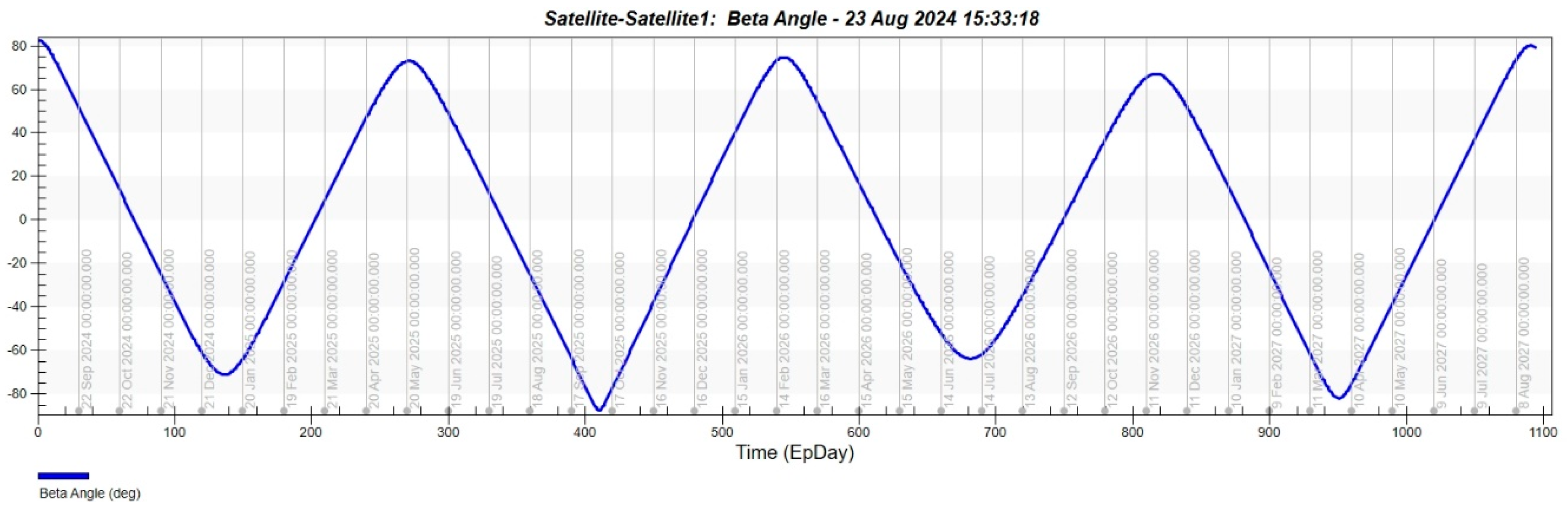
2.1. Orbit
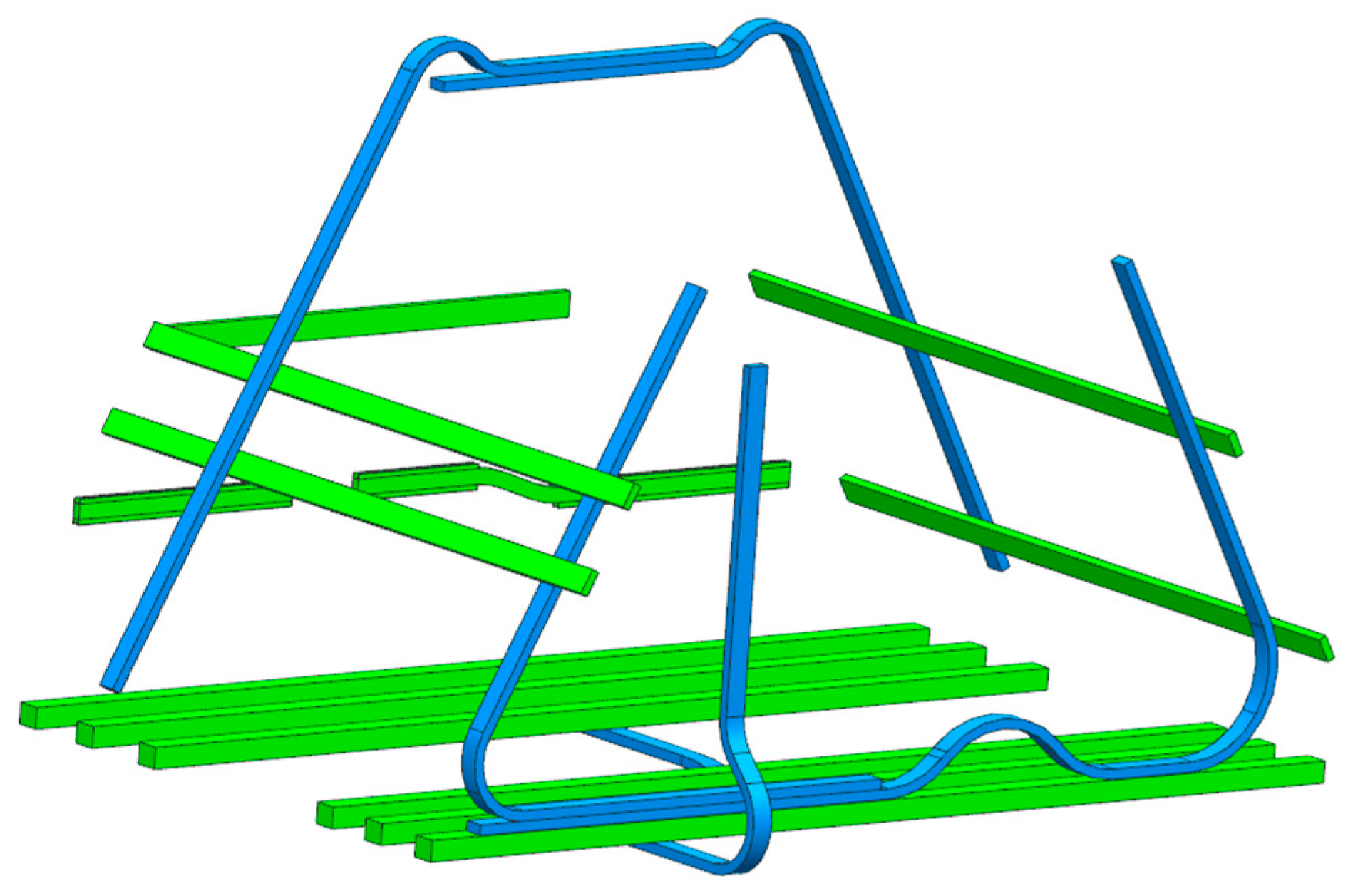
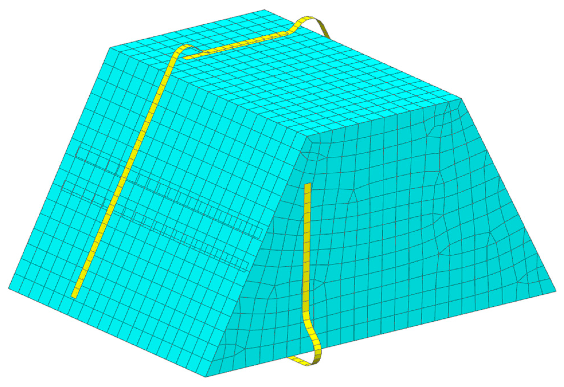
2.2. Structure
2.3. Internal Heat Source
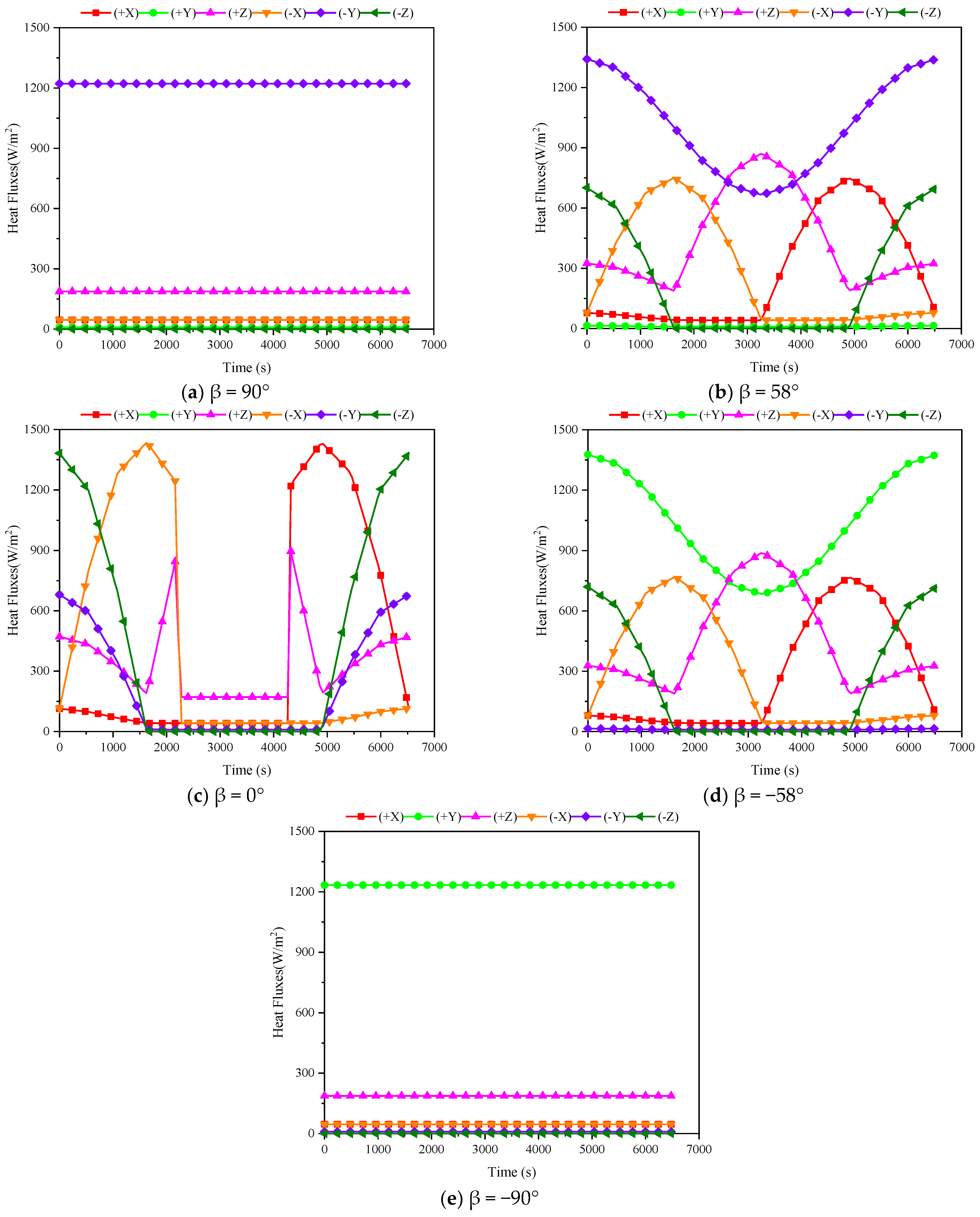
3. Heat Flux Analysis
4. Thermal Design Scheme
4.1. Thermal Design of Deck
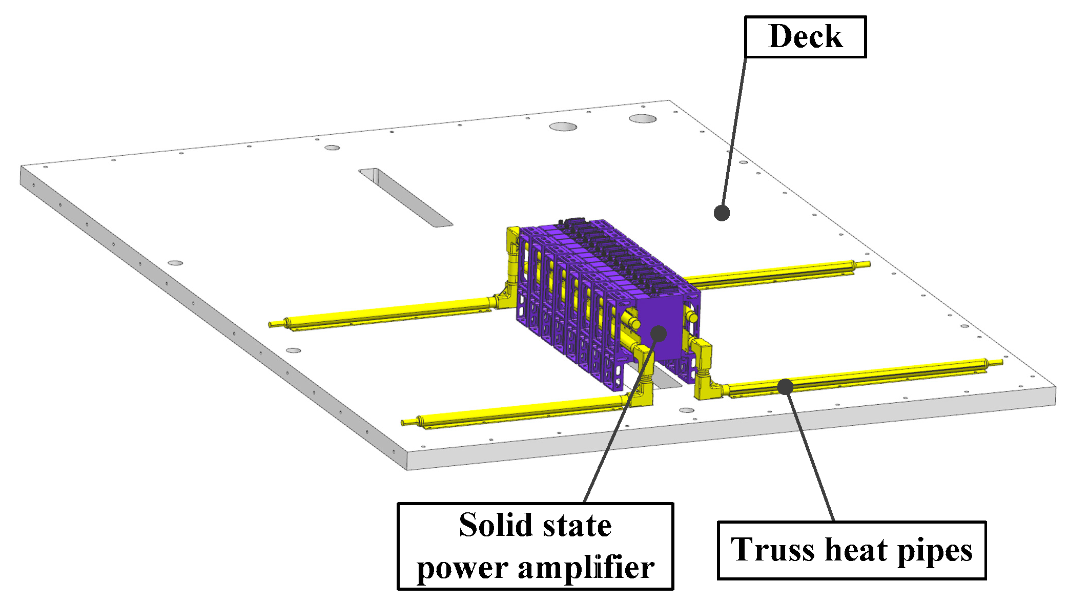
4.2. Thermal Design of High-Power Devices
4.3. Thermal Design of Active Heating Zone
4.4. Thermal Design of Special Devices
4.5. Thermal Design of Other Devices
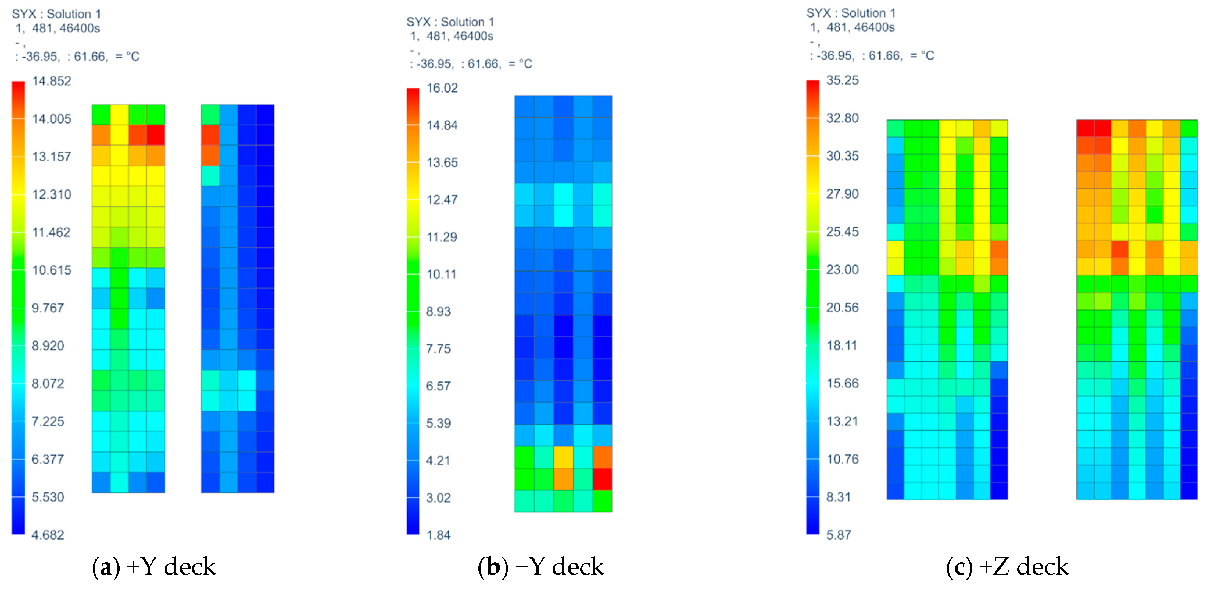
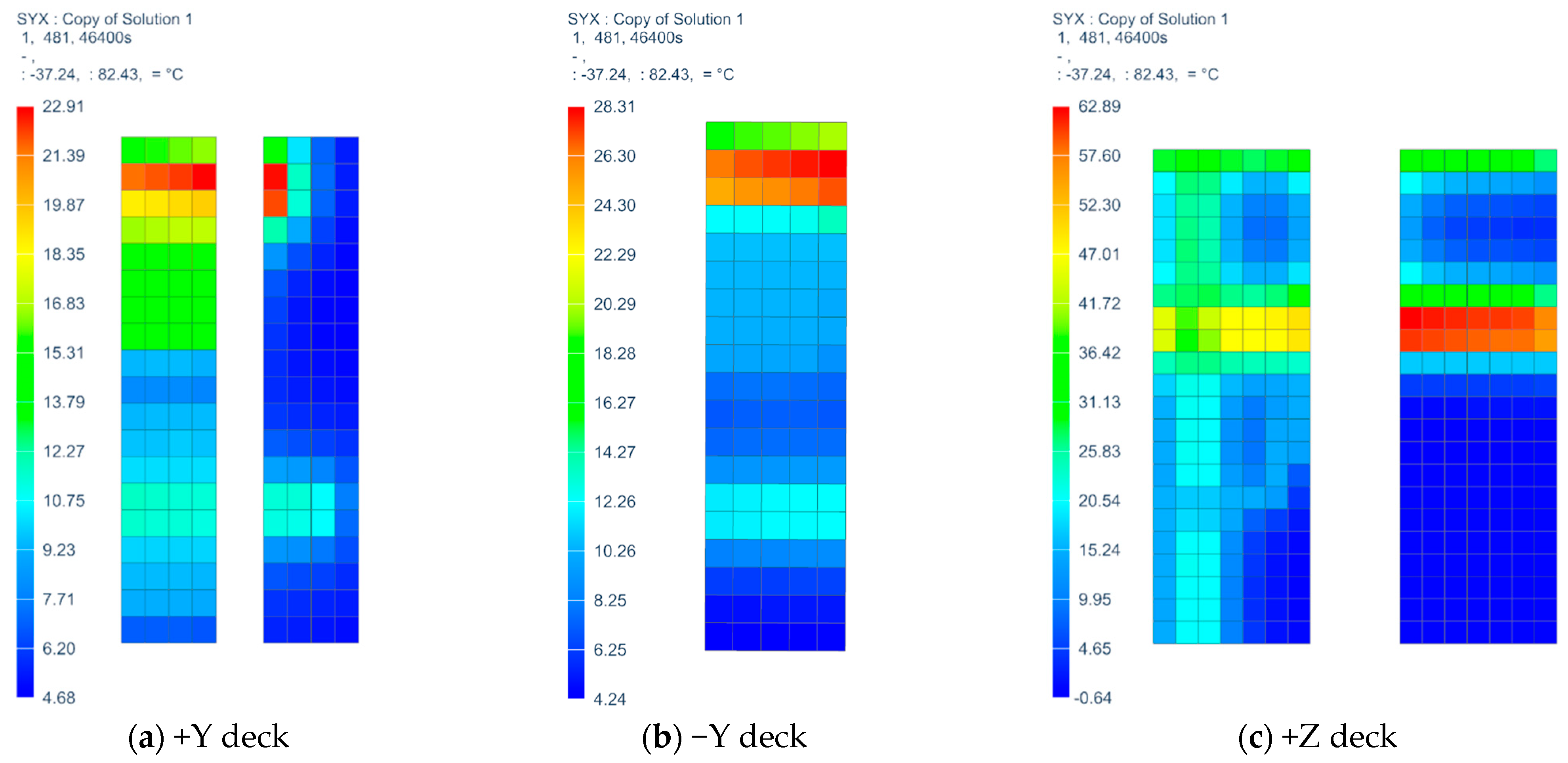
5. Evaluation of Heat Dissipation Effect of Heat Pipes
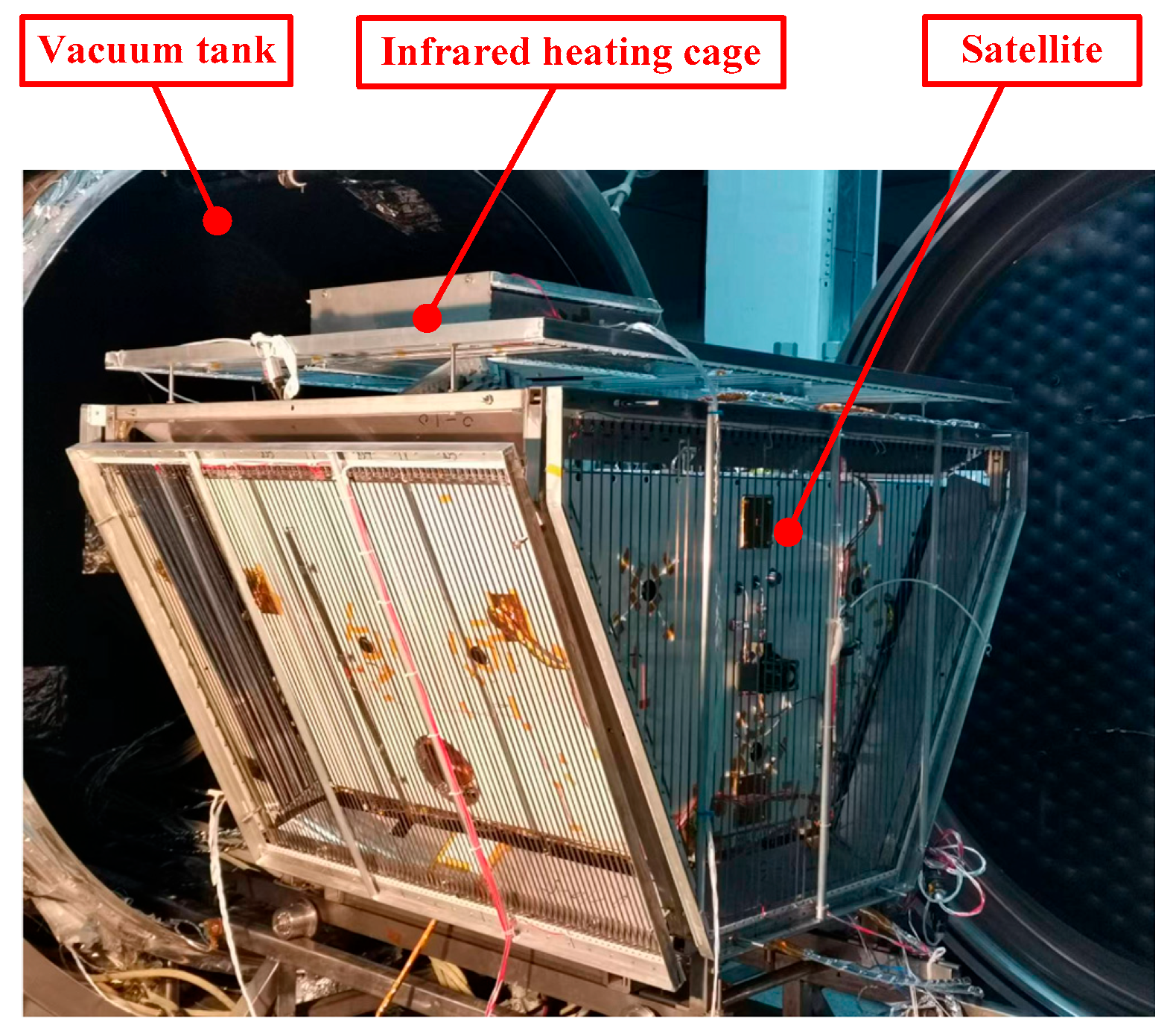
6. Thermal Balance Test
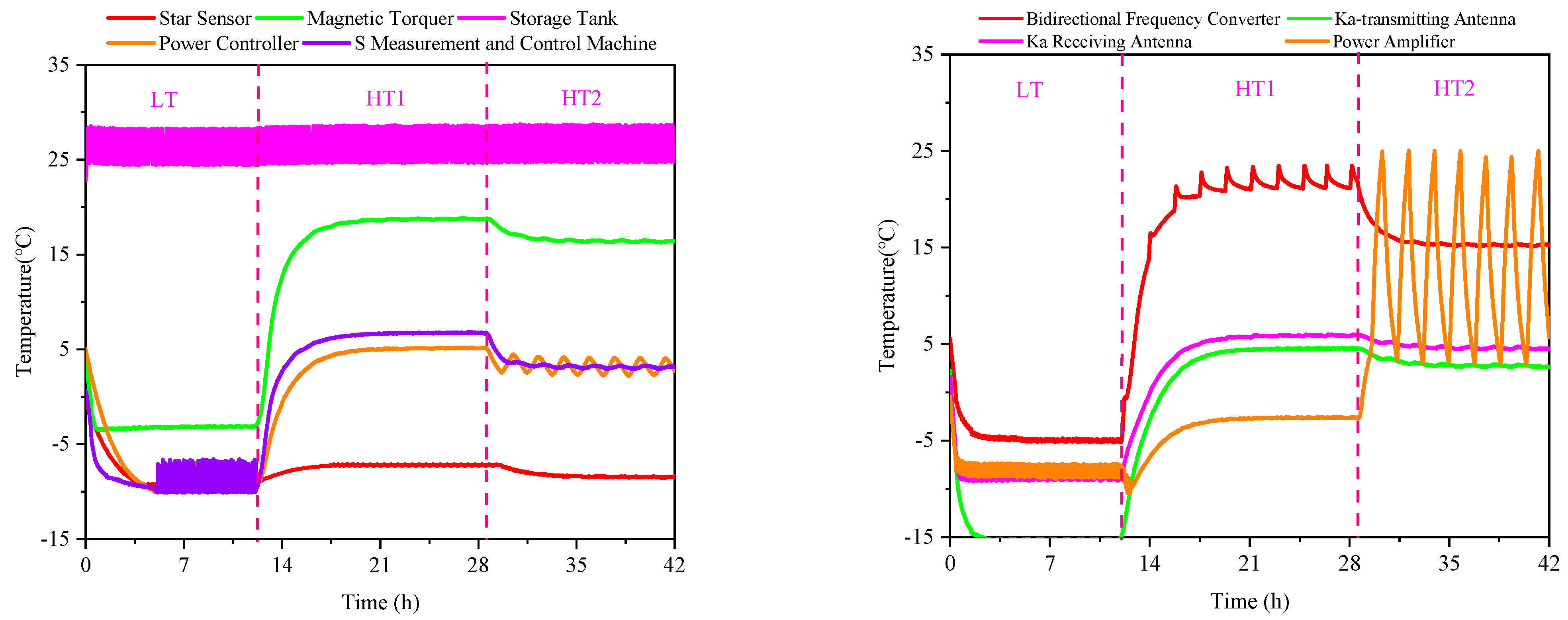
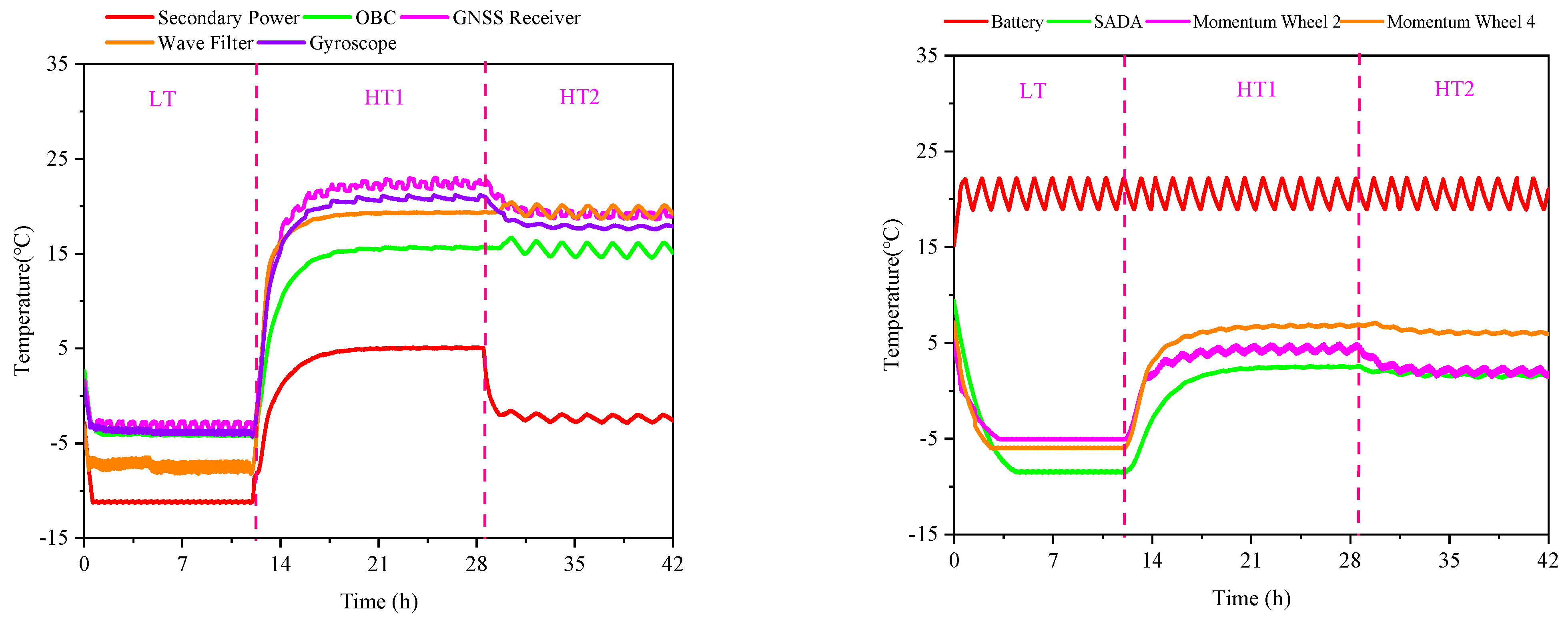
6.1. Test Scheme
6.2. Test Conditions
6.3. Test Results
7. Discussion
8. Conclusions
Author Contributions
Funding
Data Availability Statement
Acknowledgments
Conflicts of Interest
References
- Okati, N.; Riihonen, T.; Korpi, D.; Angervuori, I.; Wichman, R. Downlink coverage and rate analysis of low Earth orbit satellite constellations using stochastic geometry. IEEE Trans. Commun. 2020, 68, 5120–5134. [Google Scholar] [CrossRef]
- Al-Hourani, A. Optimal satellite constellation altitude for maximal coverage. IEEE Wirel. Commun. Lett. 2021, 10, 1444–1448. [Google Scholar] [CrossRef]
- Sippel, M.; Stappert, S.; Koch, A. Assessment of multiple mission reusable launch vehicles. J. Space Saf. Eng. 2019, 6, 165–180. [Google Scholar] [CrossRef]
- Drenthe, N.T.; Zandbergen, B.T.C.; Curran, R.; Van Pelt, M.O. Cost estimating of commercial smallsat launch vehicles. Acta Astronaut. 2019, 155, 160–169. [Google Scholar] [CrossRef]
- Giordani, M.; Zorzi, M. Non-terrestrial networks in the 6G era: Challenges and opportunities. IEEE Netw. 2020, 35, 244–251. [Google Scholar] [CrossRef]
- Fraire, J.A.; Lova, O.; Valois, F. Space-terrestrial integrated Internet of Things: Challenges and opportunities. IEEE Commun. Mag. 2022, 60, 64–70. [Google Scholar] [CrossRef]
- Chen, L.H.; Wu, Q.W.; Liu, W.Q. Thermal, design for space cameras. Opt. Precis. Eng. 2012, 20, 556–562. [Google Scholar] [CrossRef]
- Iwata, N.; Usui, T.; Miki, A.; Kaizu, Y.; Ikeda, M.; Ogawa, H.; Takahashi, T. In Proceedings of the Thermal Control Design of X-ray Astronomy Satellite ASTRO-H International Conference on Environmental Systems, San Diego, CA, USA, 15–19 July 2012.
- Park, T.Y.; Chae, B.G.; Kim, H.; Koo, K.R.; Song, S.C.; Oh, H.U. New Thermal Design Strategy to Achieve an 80-kg-Class Lightweight X-Band Active SAR Small Satellite S-STEP. Aerospace 2021, 8, 278. [Google Scholar] [CrossRef]
- Zhong, Q.; Wen, Y.P.; Li, G.Q. Influences of near-earth thermal environment parameters on spacecraft temperature: A first review. Spacecr. Eng. 2007, 16, 73–77. [Google Scholar]
- Lu, W.; Huang, J.R.; Zhong, Q. External heat flux on manned transport spacecraft with multiple modes and attitudes. Chin. Space Sci. Technol. 2011, 31, 24–32. [Google Scholar]
- Li, G.Q.; Jia, H.; Liu, Q. Analysis for some factors affecting the temperature distribution of a CCD camera. Chin. Space Sci. Technol. 2001, 21, 62–70. [Google Scholar]
- Giesen, P.; Folgering, E. Design guidelines for thermal stability in opto-mechanical instruments. SPIE 2003, 5176, 126–134. [Google Scholar]
- Zweben, C. Thermal material solve power electronics challenges. Power Electron. Technol. 2006, 32, 40–47. [Google Scholar]
- Kreeb, H.; Molt, W. Experimental evaluation of cryogenic heat pipes with various heat carriers and capillary structures. In Proceedings of the 3rd International Heat Pipe Conference, Palo Alto, CA, USA, 22–24 May 1978; Volume 421. [Google Scholar]
- Prager, R. The design and test of a neon heat pipe. In Proceedings of the 15th Thermophysics Conference, Snowmass, CO, USA, 14–16 July 1980; Volume 1484. [Google Scholar]
- Compagna, G.; Rosenfeld, J. Development of high performance sintered powder metal wick cryogenicheat pipes. In Proceedings of the 23rd Thermophysics, Plasmadynamics and Lasers Conference, San Antonio, CA, USA, 27–29 June 1988; Volume 2651. [Google Scholar]
- Lin, L.; Ponnappan, R.; Mahefkey, T. Closed loop spray cooling of high power semiconductor lasers. In Proceedings of the Sixteenth Annual Solid State and Diode Laser Technology Review Technical Digest, Albuquerque, NM, USA, 20–22 May 2003. [Google Scholar]
- Osiander, R.; Allen, J.J.; George, T.; Darrin, M.A.G.; Champion, J.L.; Firebaugh, S.L.; Buchner, S.P.; Schein, J.; Dennehy, C.J.; Gerke, R.D.; et al. MEMS and Microstructures in Aerospace Applications; CRC Press: Boca Raton, FL, USA, 2018. [Google Scholar]
- Fan, H.L. Spacecraft Thermal control material. Aerosp. Mater. Technol. 2007, 37, 7–10. [Google Scholar]
- Fan, H.L.; Fan, Y.F. Analysis of material requirements for spacecraft thermal control subsystems. Spacecr. Environ. Eng. 2010, 27, 135–138. [Google Scholar]
- Xiang, Y.C.; Gao, H. Review of Spacecraft Thermal Control Materials and Applications. Mater. Rep. 2022, 36. [Google Scholar]
- Modest, M.F. Solar flux incident on an orbiting surface after reflection from the planet. AIAA J. 1980, 18, 727–730. [Google Scholar] [CrossRef]
- Alcayde, V.; Vercher-Martínez, A.; Fuenmayor, F.J. Thermal control of a spacecraft: Backward-implicit scheme programming and coating materials analysis. Adv. Space Res. 2021, 68, 1975–1988. [Google Scholar] [CrossRef]
- Krainova, I.V.; Nenarokomov, A.V.; Nikolichev, I.A.; Titov, D.M.; Chumakov, V.A. Radiative Heat Fluxes in Orbital Space Flight. J. Eng. Thermophys. 2022, 31, 441–457. [Google Scholar] [CrossRef]
- González-Bárcena, D.; Bermejo-Ballesteros, J.; Pérez-Grande, I.; Sanz-Andrés, Á. Selection of time-dependent worst-case thermal environmental conditions for Low Earth Orbit spacecrafts. Adv. Space Res. 2022, 70, 1847–1868. [Google Scholar] [CrossRef]
- Hintze, P.E.; Quintana, S. Building a Lunar or Martian Launch Pad with In Situ Materials: Recent Laboratory and Field Studies. J. Aerosp. Eng. 2013, 26, 134–142. [Google Scholar] [CrossRef]
- Scigliano, R.; De Simone, V.; Fusaro, R.; Ferretto, D.; Viola, N.; Souza, R.R. Numerical Simulation of Heat Pipe Thermal Performance for Aerospace Cooling System Applications. Aerospace 2024, 11, 85. [Google Scholar] [CrossRef]
- Xiao, G.; Du, Y.; Gui, Y.; Liu, L.; Yang, X.; Wei, D. Heat transfer characteristics and limitations analysis of heat-pipe cooled thermal protection structure. Appl. Therm. Eng. 2014, 70, 655–664. [Google Scholar]
- Tang, H.; Lian, L.; Zhang, J.; Liu, Y. Heat transfer performance of cylindrical heat pipes with axially graded wick at anti-gravity orientations. Appl. Therm. Eng. 2019, 163, 114413. [Google Scholar] [CrossRef]
- Corpino, S.; Caldera, M.; Nichele, F.; Masoero, M.; Viola, N. Thermal design and analysis of a nanosatellite in low earth orbit. Acta Astronaut. 2015, 115, 247–261. [Google Scholar] [CrossRef]
- Daeil, P.; Kikuko, M.; Hosei, N. Thermal design and validation of radiation detector for the ChubuSat-2 micro-satellite with high-thermal-conductive graphite sheets. Acta Astronaut. 2017, 136, 387–394. [Google Scholar]
- Li, S.J.; Chen, L.H.; Liu, S. Thermal analysis model correction method based on Latin hypercube sampling and coordinate rotation method. J. Therm. Stress. 2023, 46, 857–870. [Google Scholar] [CrossRef]


| Name | β-Angle | +X | +Y | +Z | −X | −Y | −Z | Total |
|---|---|---|---|---|---|---|---|---|
| Early | 90° | 38.7 | 9.0 | 147.1 | 38.9 | 252.6 | 0.2 | 576.5 |
| 58° | 84.5 | 9.3 | 197.2 | 87.5 | 217.5 | 47.2 | 701.2 | |
| 0° | 118.1 | 47.5 | 176.1 | 118.0 | 48.5 | 79.9 | 588.1 | |
| −58° | 90.5 | 217.5 | 196.7 | 91.1 | 9.3 | 47.9 | 595 | |
| −90° | 39.0 | 252.6 | 147.4 | 39.1 | 9.0 | 0.4 | 397.5 | |
| Late | 90° | 40.3 | 9.0 | 152.2 | 40.4 | 618.1 | 0.4 | 950.4 |
| 58° | 154.7 | 9.7 | 277.2 | 162.1 | 530.4 | 117.9 | 1310 | |
| 0° | 238.6 | 105.2 | 224.5 | 238.3 | 107.8 | 199.8 | 1114.2 | |
| −58° | 169.7 | 530.2 | 276.0 | 171.1 | 9.7 | 119.7 | 1218.4 | |
| −90° | 41.0 | 618.1 | 152.8 | 41.1 | 9.0 | 1.1 | 773.1 |
| Protective Layer | Solar Absorptivity | Infrared Emissivity | |
|---|---|---|---|
| BOL | EOL | ||
| Aluminum black anodized, E51-M black lacquer | 0.85 | — | 0.85 |
| Aluminum alloy conductive oxidation | 0.25 | — | 0.85 |
| Aluminum conductive oxidation | 0.14 | — | 0.36 |
| Aluminum alloy natural color anodic oxidation | 0.55 | — | 0.7 |
| Double-sided aluminized polyester film | 0.12 | — | 0.05 |
| SR107-ZK white paint | 0.17 | 0.5 | 0.87 |
| Single-sided aluminized polyimide film | 0.35 | 0.65 | 0.69 |
| Conductive F46 silver-plated secondary surface mirror | 0.13 | 0.4 | 0.67 |
| Name | With Heat Pipes | Without Heat Pipes | |
|---|---|---|---|
| +Y deck | 10.2 | 18.2 | 8 |
| −Y deck | 14.2 | 24.1 | 9.9 |
| +Z deck | 29.3 | 63.5 | 34.2 |
| Name | With Heat Pipes | Without Heat Pipes | T2max − T1max |
|---|---|---|---|
| Temperature (T1max) | Temperature (T2max) | ||
| Power controller | 15.0 | 47.5 | 32.5 |
| Secondary power | 16.0 | 38.0 | 22.0 |
| Bidirectional frequency converter | 35.0 | 49.0 | 14.0 |
| Power amplifier | 51.0 | 215.0 | 164.0 |
| Number | Condition Name | Main Setting Conditions |
|---|---|---|
| 1 | Low-temperature condition (LT) | The β-angle is 90° and the solar constant is 1322 W/m2. The performance parameter of MLI is αs/ε = 0.36/0.69, and the performance parameter of SR107-ZK white paint is αs/ε = 0.17/0.87. The active thermal control works continuously. Platform equipment is long-term operational. Payload turns off. |
| 2 | High-temperature condition 1 (HT1) | The β-angle is 58° and the solar constant is 1414 W/m2. The performance parameter of MLI is αs/ε = 0.64/0.69, and the performance parameter of SR107-ZK white paint is αs/ε = 0.5/0.87. The active thermal control works continuously. Platform equipment is long-term operational. Payload turns on. |
| 3 | High-temperature condition 2 (HT2) | The β-angle is 0° and the solar constant is 1414 W/m2. The performance parameter of MLI is αs/ε = 0.64/0.69, and the performance parameter of SR107-ZK white paint is αs/ε = 0.5/0.87. The active thermal control works continuously. Platform equipment is long-term operational. Payload turns on. |
| Name | LT | HT1 | HT2 | Thermal Control Indicators | ||||
|---|---|---|---|---|---|---|---|---|
| Min | Max | Min | Max | Min | Max | Min | Max | |
| Star Sensor | −11.4 | −9.2 | −7.3 | −7.1 | −8.6 | −8.3 | −40 | 45 |
| Gyroscope | −7.2 | −3.6 | 5.8 | 21.2 | 3.0 | 18.0 | −20 | 45 |
| Magnetic Torquer | −5.2 | −2.1 | 5.8 | 18.8 | 3.9 | 16.5 | −20 | 55 |
| Storage Tank | 24.4 | 28.3 | 24.7 | 28.6 | 24.7 | 28.7 | 20 | 45 |
| Power Controller | −10.1 | −9.9 | 5.0 | 5.2 | 2.2 | 4.1 | −20 | 55 |
| S Measurement and Control Machine | −10.1 | −6.6 | 6.7 | 6.8 | 2.9 | 3.3 | −20 | 55 |
| Secondary Power | −11.3 | −11.1 | 5.0 | 5.1 | −2.9 | −2.0 | −25 | 45 |
| On-Board Computer | −4.2 | −4.0 | 15.5 | 15.7 | 14.6 | 16.1 | −20 | 55 |
| GNSS Receiver | −3.6 | −2.7 | 21.8 | 23.0 | 18.7 | 19.6 | −20 | 55 |
| Wave Filter | −9.3 | −6.9 | 16.5 | 19.4 | 16.5 | 20.1 | −40 | 80 |
| Bidirectional Frequency Converter | −5.2 | −4.7 | 21.1 | 23.5 | 15.1 | 15.4 | −15 | 55 |
| Ka-Transmitting Antenna | −15.4 | −15.2 | 4.4 | 4.6 | 2.6 | 2.9 | −90 | 90 |
| Ka-Receiving Antenna | −9.1 | −8.7 | 5.8 | 6.0 | 4.4 | 4.7 | −90 | 90 |
| Solid-State Power Amplifier | −8.9 | −7.4 | −2.7 | −2.5 | 3.0 | 25.1 | −20 | 50 |
| Battery | 19.0 | 23.1 | 18.9 | 22.8 | 19.0 | 23.1 | 10 | 30 |
| SADA | −8.5 | −8.4 | 2.4 | 2.6 | 1.4 | 1.8 | −15 | 45 |
| Momentum Wheel | −6.0 | −4.6 | 3.9 | 6.9 | 1.5 | 6.2 | −20 | 50 |
Disclaimer/Publisher’s Note: The statements, opinions and data contained in all publications are solely those of the individual author(s) and contributor(s) and not of MDPI and/or the editor(s). MDPI and/or the editor(s) disclaim responsibility for any injury to people or property resulting from any ideas, methods, instructions or products referred to in the content. |
© 2024 by the authors. Licensee MDPI, Basel, Switzerland. This article is an open access article distributed under the terms and conditions of the Creative Commons Attribution (CC BY) license (https://creativecommons.org/licenses/by/4.0/).
Share and Cite
Huang, H.; Bu, C. Design and Verification of Thermal Control System of Communication Satellite. Aerospace 2024, 11, 803. https://doi.org/10.3390/aerospace11100803
Huang H, Bu C. Design and Verification of Thermal Control System of Communication Satellite. Aerospace. 2024; 11(10):803. https://doi.org/10.3390/aerospace11100803
Chicago/Turabian StyleHuang, Hongzhou, and Changgen Bu. 2024. "Design and Verification of Thermal Control System of Communication Satellite" Aerospace 11, no. 10: 803. https://doi.org/10.3390/aerospace11100803