Article

Method for Underground Motion Using Vibration-Induced Ground Resistance Changes for Planetary Exploration

1
Mechanical Engineering Program, Niigata University, Niigata 950-2181, Japan
2
Advanced Materials Science and Technology, Graduate School of Science and Technology, Niigata University, Niigata 950-2181, Japan
3
Department of Systems and Engineering and Science, Shibaura Institute of Technology, Saitama 337-8570, Japan
*
Author to whom correspondence should be addressed.
These authors contributed equally to this work.
Aerospace 2024, 11(10), 811; https://doi.org/10.3390/aerospace11100811
Submission received: 21 July 2024 / Revised: 30 August 2024 / Accepted: 27 September 2024 / Published: 3 October 2024
(This article belongs to the Special Issue Planetary Exploration)

Abstract

:
Exploration rovers have difficulty moving underground because the drag force from the ground restricts their movement; this hinders underground exploration. This study aimed to address this challenge. We posit a hypothesis that the rover can move underground by imparting vibration to the ground and changing the drag force. To validate this hypothesis, a testbed that moves underground was developed, and the drag force when imparting vibration was investigated. The results revealed that the drag force while imparting vibration is smaller than that after imparting vibration, and we accordingly devised the operation for moving underground. The proposed operation causes bias of the drag force by imparting vibration to make the testbed move in the direction of the small drag force. The effectiveness of the proposed method was assessed through an experiment wherein the testbed was set to move underground. The experimental results demonstrate the superiority of the proposed method, as the movement distance achieved with vibration is considerably greater than that without vibration. The findings validate the hypothesis that using vibration for underground motion is effective in improving mobility and provides valuable insights into the design of robots for underground motion.

1. Introduction

1.1. Importance of Space Development and Current Situation of Extraterrestrial Body Exploration

Space exploration provides valuable scientific knowledge and has research significance. For example, these results help elucidate the origins of planets. Some celestial bodies, such as Mars, indicate the possibility of life traces. Investigating these hypotheses is valuable for probing the existence of extraterrestrial life. Moreover, advancement of space technology is crucial for human progress. Recently, celestial bodies, including the Moon and asteroids, have shown the possibility of possessing natural resources. Studies on the technology and economic effect of mining these natural resources have been conducted for use on Earth or the Moon [1,2,3].
Accordingly, numerous missions comprising rovers landing and exploring the surface of planets or other extraterrestrial bodies have been conducted. Such missions offer merit in that the samples of extraterrestrial ground are meticulously investigated. For example, Chang’E-5, developed by China, landed on the Moon in 2020 and successfully completed a sample-return mission for progressing the science behind the origin of the Moon [4]. This investigation and its samples have progressed the understanding of the existence of water on the Moon [5]. Perseverance, the rover developed by the National Aeronautics and Space Administration (NASA), reached Mars in 2021 to investigate the ground environment and find signs of ancient microbial life [6]. The mission plans to return soil samples of Mars to Earth. In the future, the Indian Space Research Organisation (ISRO) and the Japan Aerospace Exploration Agency (JAXA) plan to launch the Lunar Polar Exploration Mission (LUPEX) to investigate the presence of water in the lunar south-polar region [7]. Furthermore, JAXA plans to launch the Martian Moons eXploration (MMX) in 2026 [8], where the spacecraft is expected to explore the moons of Mars and return soil samples to Earth. The knowledge obtained from such missions is anticipated to solve the mysteries of planet origins. These missions also hold significant engineering value, as information on terramechanics—concerning the interaction forces between ground and mobile objects—is helpful when mining resources and building bases. Moreover, the technological advancement achieved through these space exploration missions is utilized to develop robots that function outdoors on Earth (e.g., smart agriculture and rescue robots). For example, Kisuitech Co., Ltd. (Sendai city, Japan), developed an unmanned ground vehicle (UGV) for automating agriculture works [9]. The UGV is navigated by the mapping system without GPS, which was developed by utilizing navigation technology for space exploration.
The opportunities to access extraterrestrial bodies have increased with improved space exploration technology. Smart Lander for Investigating Moon (SLIM), developed by JAXA, successfully landed on the Moon and delivered the two mobile rovers it carried internally [10]. The Gateway, a platform orbiting the Moon, is currently under development primarily by NASA [11]. The Gateway plans to send robots to the surface of the Moon. Thus, the demand and opportunity to deploy various rovers on the Moon are anticipated to increase.

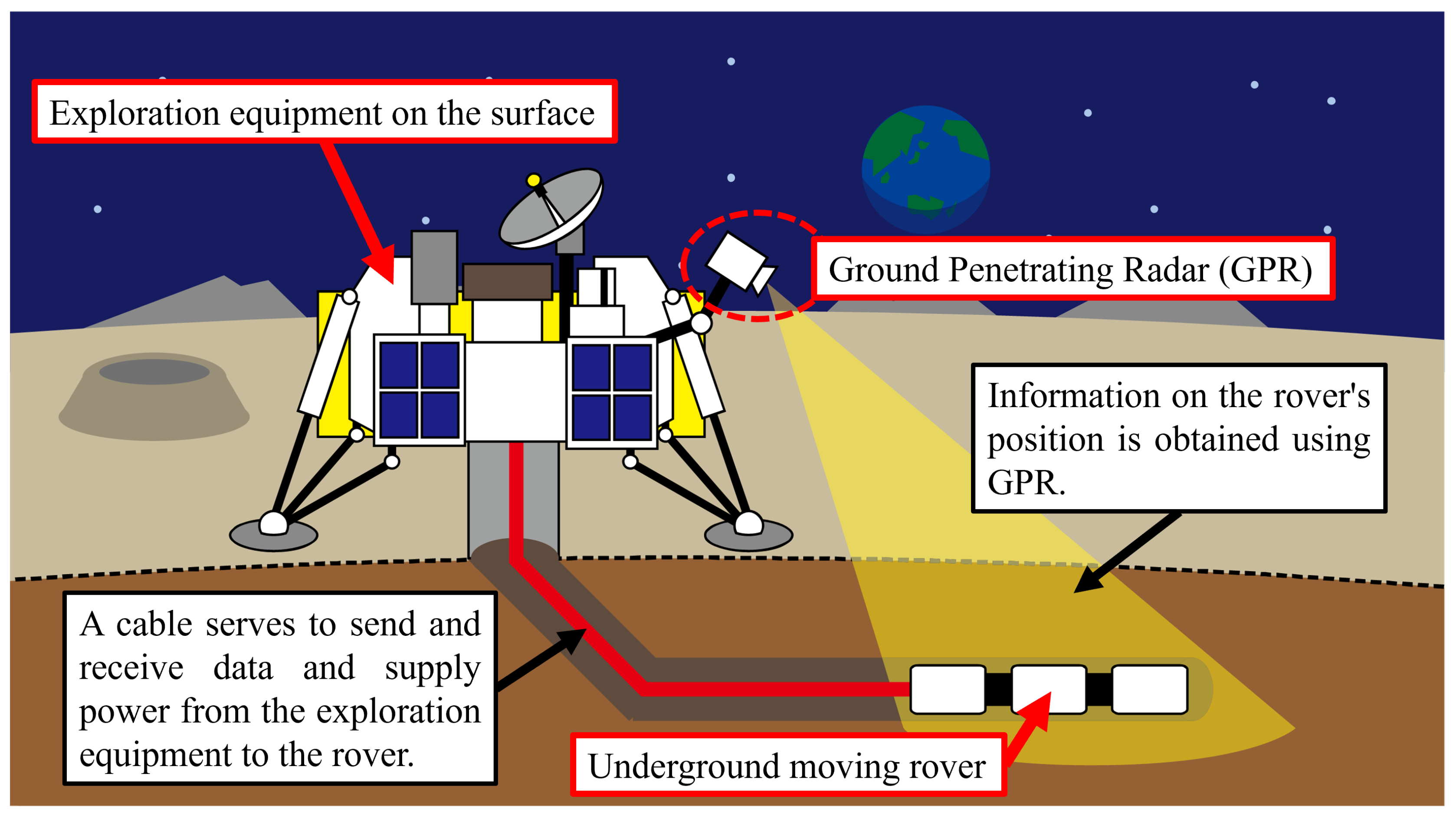
1.2. Importance of Underground Exploration

Recently, valuable missions have focused on underground explorations of extraterrestrial bodies because underground soil samples are particularly valuable, as they remain in good condition and are unaffected by space weathering. Space weathering is weathering that affects objects in space. On planetary bodies without an atmosphere, galactic and solar cosmic rays collide with the ground and change the surface of planetary bodies physically and chemically. JAXA developed HAYABUSA2 to investigate the asteroid RYUGU [12]. When sampling the soil sample of RYUGU, HAYABUSA2 created an artificial crater on RYUGU to obtain underground soil that remained unaffected by space weathering.
Additionally, moving underground exhibits the advantage of rover protection from severe temperature changes. The Moon has maximum and minimum temperatures of 121 °C and −133 °C, respectively [13]. These extreme temperature changes can damage the electronic devices on rovers. Alternatively, the ground absorbs heat and maintains a constant temperature internally. Therefore, rovers can protect their electronic devices when underground. Notsu et al. proposed a lunar long-duration method for spacecraft using the very low thermal conductivity characteristics of the lunar regolith [14]. They confirmed the feasibility of their proposed thermal control method via simulation and experiments.
Accordingly, rovers moving underground have been developed. Nakatake et al. focused on the peristaltic movement of earthworms as a mechanism to move underground and developed a robot [15]. Their robot comprised some units that expanded and shrank to reproduce the peristaltic movement. Furthermore, Naclerio et al. developed a mechanism that moved underground. The mechanism outputted air from the front of its head to decrease the drag force to move forward [16]. However, such structures on robots are highly complex as they require a mechanism that affects the ground. Underground motion for extraterrestrial body exploration should be a simple mechanism so as to decrease the risk of damage and increased energy consumption.
We herein detail the plan for the exploration mission using the underground moving rover. We estimate it based on the related studies. Figure 1 shows an overview of the plan for the exploration mission. The exploration system is constructed of the exploration equipment on the surface and the underground moving rover. The large rover or lander is assigned to the exploration equipment on the surface. The exploration equipment on the surface connects to the underground moving rover by cable. The cable sends and receives data and supplies power from the exploration equipment to the rover. The mission using the cable is planned for the exploration of lunar holes. The explorations of the holes and underground have a common challenge in that it is difficult to supply power. Nesnas et al. proposed the mission for lunar holes, which combines the lander and rover, which is good at moving on rough terrain [17]. The rover connects to the lander by the tether. The lander sends data to Earth and supports the rover’s movement as the anchor. The rover stabilizes its posture using the tether and enters the lunar holes. The exploration system on the surface is equipped with ground penetrating radar (GPR), which is used to obtain information on the rover’s position. GPR is considered to accompany space exploration equipment, and the LUPEX lander plans to incorporate GPR [7]. Moreover, Yuan et al. developed a drilling underground rover with a screw [18]. They considered a method where obstacles underground, such as rocks, are mapped by lunar penetrating radar (LPR), and the rover is navigated.

1.3. Study Overview

This study devised a mechanism for underground motion using vibrations to alter the ground. Ground pressure in the earth changes depending on the imparted vibration because the contact conditions of ground particles alter. In the proposed method, a testbed moves underground by altering the ground pressure.
This paper is primarily divided into five sections. Section 2 discusses the problems of moving underground and methods adopted by organisms. Furthermore, the changes in the ground conditions (ground particle movement, density, and underground forces) due to vibrations are explained, and the testbed that moves underground using vibrations is proposed. Section 3 describes resistance force investigations from ground to object to propose the operation of the testbed moving underground using vibration. The object serves as a vibration generator and imparts vibration to the ground. This investigation verifies the dependency of resistance force change on how vibration is imparted. From the obtained results, we propose an operation method to alter the resistance force for underground motion. Section 4 discusses the development of the testbed that moves underground using vibration via experiments. The experimental results demonstrate the testbed mobility improvements due to vibration. Moreover, the relationship between vibration type and the mobility of the proposed underground motion method is discussed. The testbed moves underground using some kinds of vibrations. The mobility of the proposed method has been related to the strength of vibration. Finally, Section 5 summarizes this study.

2. Proposal of Underground Movement Using Vibration

This section first explains the forces that arise when moving underground and discusses the organisms that move underground. As indicated by the discussion, they control the forces imparted by the ground to move underground. Thereafter, imparting vibration is described, focusing on the motion that controls the forces of the ground, and examples of vibration used for movement methods are introduced. Finally, the testbed that moves underground is introduced. Its design is based on the mechanism of the organisms that move underground and the changes in the ground due to vibration.

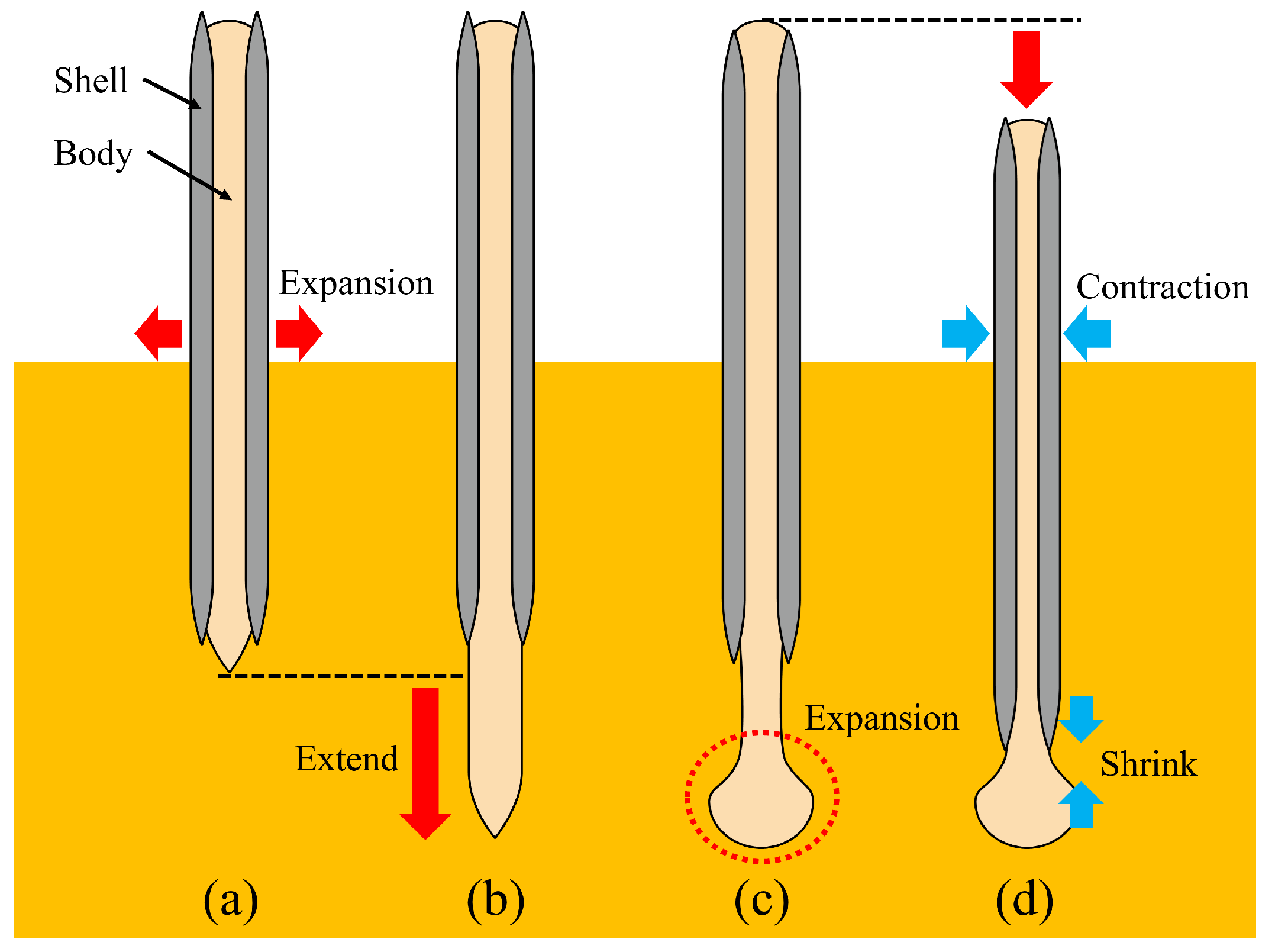
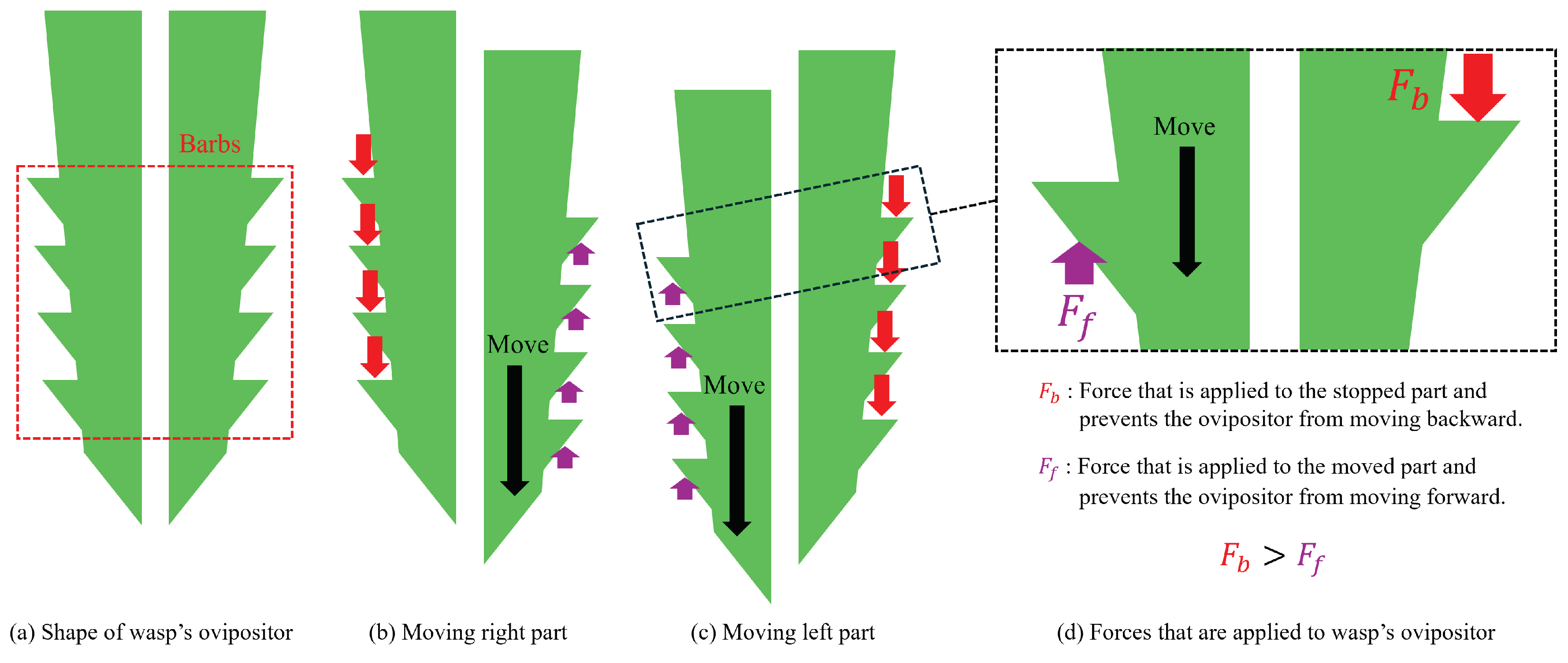
2.1. Underground Movement of Organisms

When a robot moves underground, it receives two main forces from the ground, as shown in Figure 2a. The first is the drag force, which directly resists movement, primarily due to pushing away the front ground in the direction of movement. A robot faces challenges when moving underground because the drag force is caused in the opposite direction of travel, preventing the robot from moving. The second is the lift force, which lifts the robot to the upper side of the ground. When an object moves underground, it lifts the upper side ground and compacts under the side ground, as shown in Figure 2b. In this condition, the object receives a lift force because it is easier to lift the upper side of the ground than compact it down. Such a force can divert robots from their intended course.
Some organisms move underground by efficiently controlling the drag force and the lift force. An example of an animal that moves underground is the razor clam. Razor clams are a species of marine bivalve mollusk with an elongated, oval, narrow shell. They inhabit sandy beaches and move underground. Figure 3 shows the movement of a razor clam [19].
Additionally, earthworms are organisms that move underground; they have long, cylindrical bodies comprising segments made of muscles. These muscles expand and shrink. Several fine bristles are present on the surface of earthworms. During movement, the bristles fix the body to the ground. Figure 4 shows the movement of an earthworm [15]. Earthworms exhibit a type of movement called peristalsis. During peristalsis, some segments of the earthworm expand to press their bristles against the ground to fix the body. Simultaneously, other segments shrink to move forward. Earthworms can move forward by switching their expand and shrink segments rhythmically.
A notable example of an organism that can efficiently penetrate objects by using its stinger is the wasp. Figure 5a shows the structure of the wasp’s ovipositor [20]. The ovipositor consists of two parts, the top of which has many barbs. The two parts move forward alternately when the ovipositor penetrates the object (Figure 5b,c). Figure 5d shows the forces on the wasp’s ovipositor when penetrating. F b is the force that acts on the stopped part and prevents the ovipositor from moving backward. F f is the force acting on the moved part and prevents the ovipositor from moving forward. The ovipositor can move forward into the object because the shape of the barbs makes F b larger than F f .
The organisms, which are shown in Figure 3 and Figure 4, combine forward motion with one that controls the force exerted by the ground, changing their body shape according to the latter. Thus, such solutions are effective for moving underground. However, reproducing the mechanism mechanically is challenging. Soft materials and numerous actuators are necessary to change the body shape of a robot. However, such materials lack durability in extreme space environments. Increasing the number of actuators can lead to robot damage and increased energy consumption. Therefore, the motion that controls the force exerted by the ground must be a suitable mechanism for deploying robots underground. The wasp’s ovipositor, as shown in Figure 5, makes the drag force small by its shape and penetrates easily. However, this method moves only in one direction and restricts the movement direction.

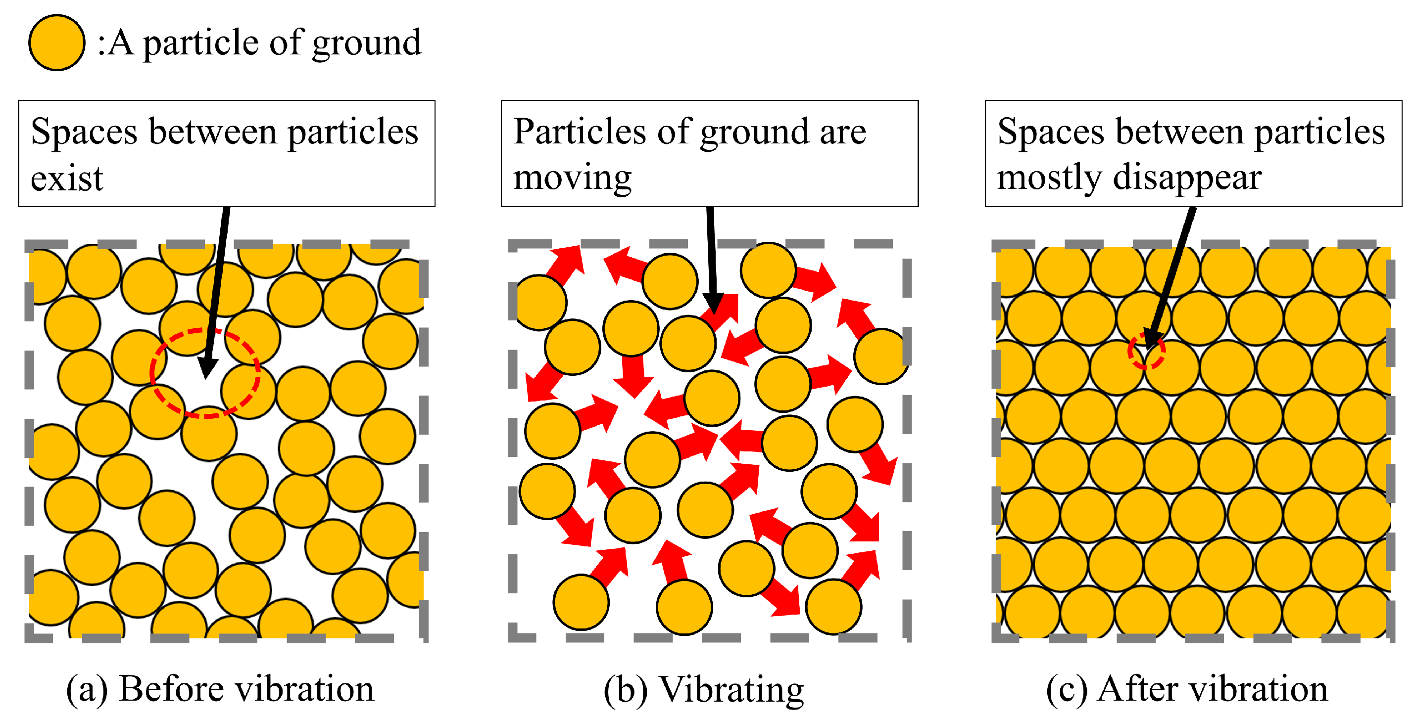
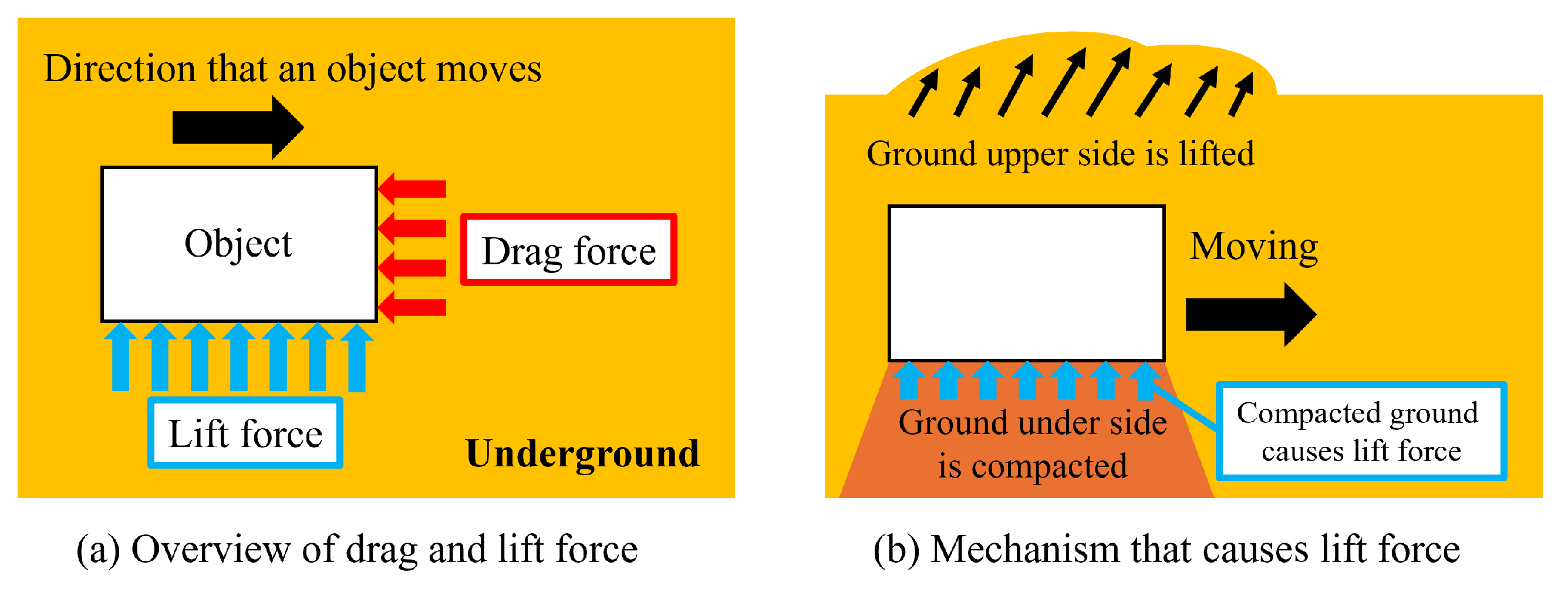
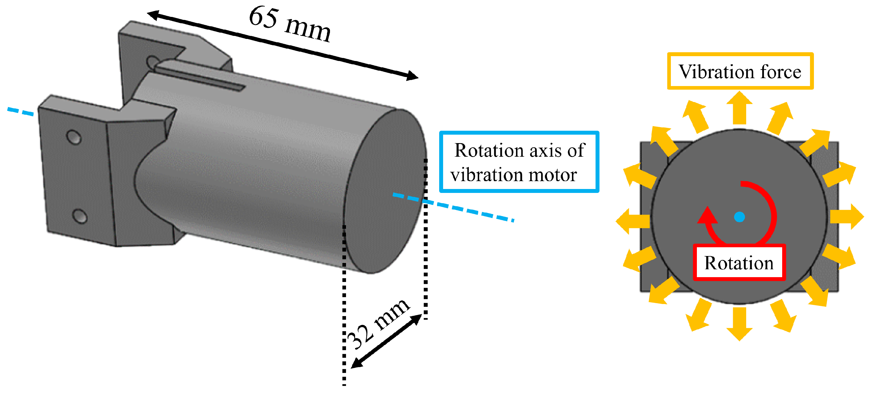
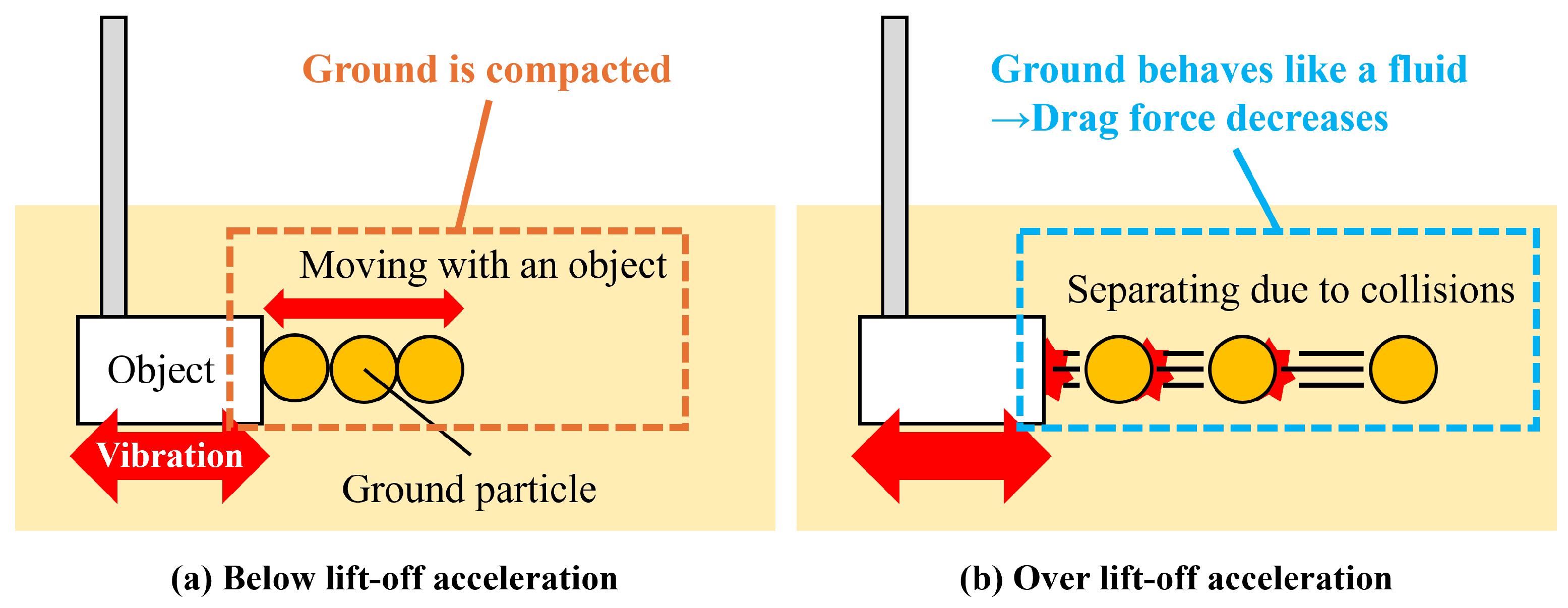
2.2. Changes in the Ground by Vibration

As mentioned in Section 2.1, the motion that controls the force exerted by the ground is essential for moving underground. We focused on imparting vibration to the ground as this motion. By imparting vibration to the ground, the ground particle movement, density, and ground reaction forces are changed, and these changes have been used to realize the movement in loose ground. These examples are introduced below.
First, in a previous study, we proposed a walking method based on vibration to prevent legged rovers from slipping on loose ground [21]. In the proposed method, the vibrators were stored in the legs of the rover and imparted vibration from the legs to the ground. We aimed to increase the density of loose ground and leg sinkage by imparting vibration. Figure 6 shows the ground movement when imparting vibration. Before imparting vibrations, spaces existed between the particles (Figure 6a). While imparting vibration, the ground particles exhibited fluid-like motion (Figure 6b). Herein, the shear strength of the ground decreased by releasing particle contacts. Moreover, the leg easily sinks to the ground by reducing the shear strength. After the vibration ceased, the spaces between the particles mostly disappeared (Figure 6c). The ground was compacted in this condition, and the shear strength and density increased. When these parameters are increased, the supporting force increases. The supporting force is the resistance force exerted on the legs of the rovers by the ground. When the supporting force is increased by applying vibration and after stopping, rovers do not easily slip. These effects due to vibration have been confirmed using multi-legged rovers. In experimental studies, the walking distance of proposed rovers with vibration is longer than that without vibration. The results demonstrate the effectiveness of vibration for locomotion on loose ground.
Second, a biological example that employs vibrations is introduced. A sandfish skink is a type of lizard that can move through desert sand using vibration. It exhibits a meandering motion by bending its body when moving underground. This motion makes vibration. Vibration made by a sandfish skink renders a local decompaction of the sand surrounding itself, causing the sand to behave like a fluid. A sandfish skink can move efficiently underground because vibration reduces the ground resistance. Baumgartner et al. explored the locomotion of sandfish skink in loose ground using fast nuclear magnetic resonance (NMR) imaging [22]. They confirmed that its locomotion caused vibration and decreased the resistance in the ground.
Referring to previous studies [21,23], we considered imparting vibration to the ground as a method for controlling the received ground forces; the changes in the ground when imparting vibrations are explained by referring to the related study. While imparting vibration, the shear strength of the ground decreased by releasing particle contacts, as shown in Figure 6b. Moreover, the drag force is considered to decrease by reducing the shear strength. After the vibration ceased, the ground was compacted, and the shear strength and density increased, as shown in Figure 6c. The drag force is considered to increase with shear strength. Therefore, we assumed that the drag force could be controlled by imparting vibration to the ground. Moreover, we propose a robot that moves forward underground, controlling the drag force via vibration.
Figure 6. Movement of ground particles when vibrations are imparted, referred from [23].
Aerospace 11 00811 g006

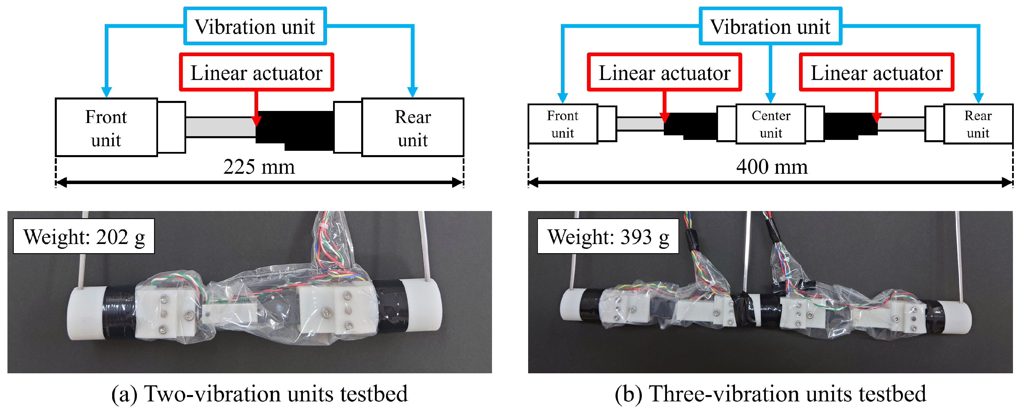
2.3. Proposal of a Testbed That Moves Underground

The mechanism of the proposed testbed for moving underground is discussed. As explained in Section 2.1, the underground movement of organisms comprises forward motion and that which controls the force exerted by the ground. In the proposed method, the motion that controls the force exerted by the ground was expressed as imparting vibration, as introduced in Section 2.2. A linear operation was selected as the forward motion by referencing a razor clam and earthworm, as introduced in Section 2.1. Figure 7 shows the constructional details of the proposed testbed. The testbed was constructed using vibration units connected by linear actuators. The vibration unit stored the vibration motor internally. Figure 8 shows the size and shape of the vibration unit. The shape of vibration unit is a simple cylinder because the changes in the underground forces by vibration are the focus of this study. The testbed’s linear actuator moves at a speed of 3.34 mm/s and extends to 30 mm. Two types of testbeds were considered, comprising two and three vibration units. Table 1 presents the specifications of the testbed.
The rotation axis of the vibration motor is attached to an unbalanced load. Vibration is generated by rotating the load. Except for the unbalanced load, the rotation axis of the vibration motor is not loaded from the outside when generating vibration. Therefore, we considered that the vibration motor is difficult to break in comparison with other actuators that were used in the studies described in Section 1.2 [15,16] for changing ground conditions because the other actuators have complex mechanisms and are loaded largely from the ground.

3. Measurement of Forces in the Ground

To construct the operation of the testbed moving underground, the changes in drag force due to vibration are essential to investigate. Additionally, the lift force should be investigated because it lifts the robot to the ground surface. Therefore, this section investigates the relationship between such forces and ways to impart vibrations. Finally, the operation of the testbed moving underground using vibration is proposed based on the experimental results.

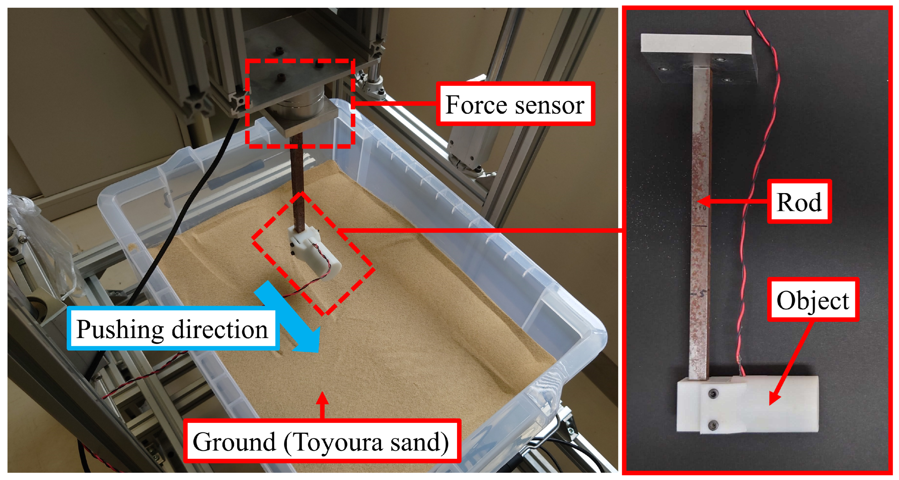
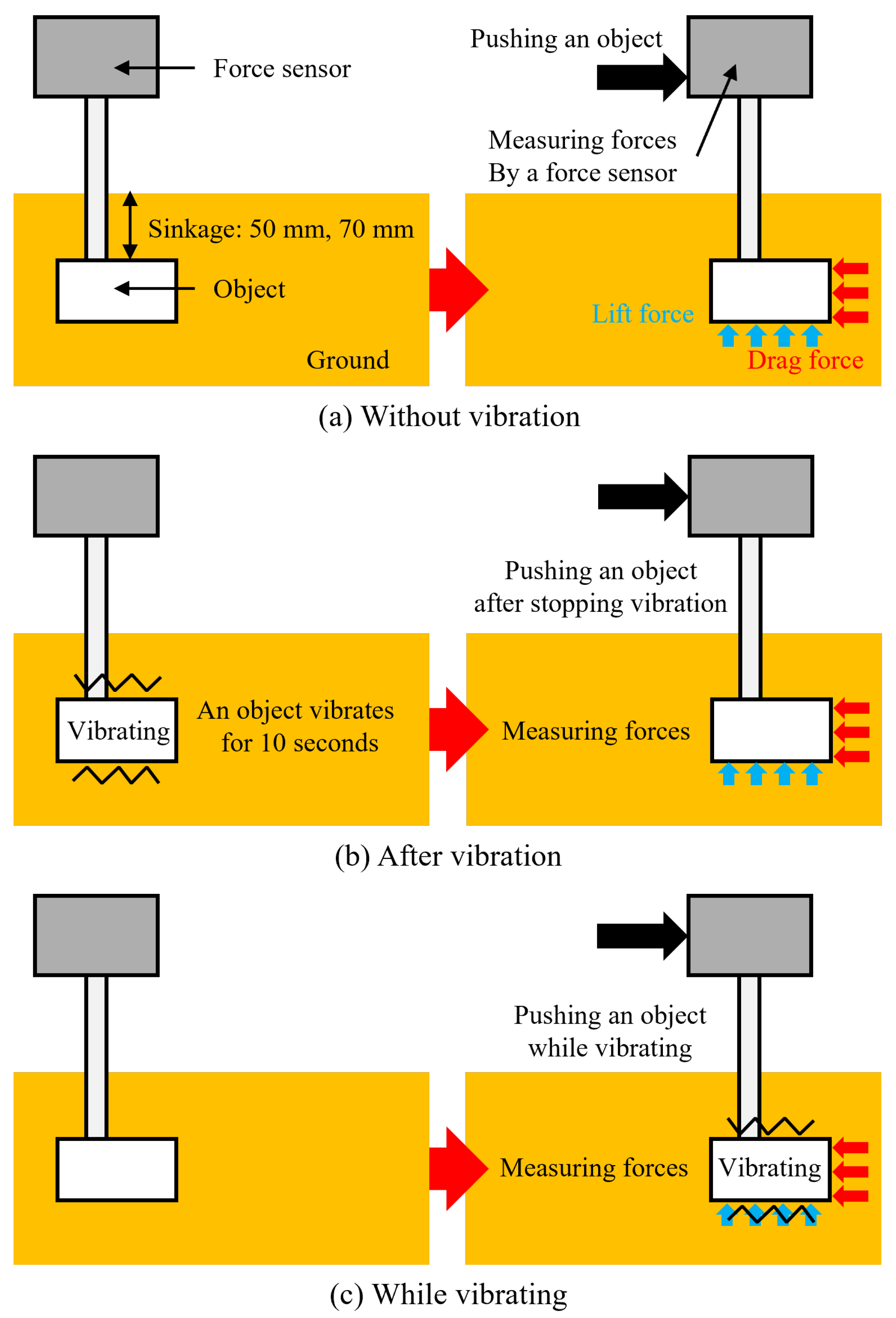
3.1. Experimental Methods

We devised the experimental method used in this study based on related studies that measured forces when an object was pushed horizontally on the ground to evaluate a planetary exploration device on loose ground [24,25] and employed the same.
Figure 9 shows the experimental setup comprising a soil tank, pushing object, and force sensor. The size and shape of the pushing object are the same as the vibration unit of the testbed, which is shown in Figure 8. Figure 10 outlines the experimental procedure. Initially, ground soil was mixed and flattened, after which a rod was positioned on the ground with a sinkage of 50 and 70 mm. The ground’s shear strength was measured using a hand vane before conducting all experiments to confirm the ground conditions. The shear strength can be used to evaluate the bulk density and compaction of the ground. The values of shear strength, which were measured in all experiments, range from 0.30 cN·m to 0.51 cN·m. Therefore, we consider that the experimental ground conditions remain constant. Further, the object was pushed, and the drag force and lift force values were measured using the force sensor. The rod was moved at a speed of 4.17 mm/s and pushed for 10 s. The pushing speed of the rod was close to the speed for the operation of the testbed’s linear actuator. The time for moving the rod was set based on the testbed’s specifications. The testbed’s linear actuator extends to 30 mm. The moving time was set to 10 s because the rod moved over 30 mm. These forces were measured for some vibrational patterns. First, the object was pushed without vibration (Figure 10a). Second, the object was pushed after generating vibrations for 10 s (Figure 10b). Third, the object was pushed while vibrating (Figure 10c). The soil tank had dimensional length, width, and height of 309, 439, and 300 mm, respectively. The ground material comprised Toyoura sand, a type of sand commonly used in studies of planetary exploration rovers [26,27,28]. Our investigation was slightly different from the actual conditions. In our experiment, the rod connecting the force sensor and the object received a force from the ground. The measured drag force and lift force values included that force. To reduce the effect of the rod, the rod thickness should be as thin as possible. The cross-section of the rod was square, with sides of 10 mm. The rod’s influence on these forces is evaluated in Appendix A. The vibrations were of three types, produced by changing the voltage supplied to the vibration motor. The larger the supplied voltage, the higher the vibration force and frequency. Table 2 lists the vibrations. The details of measuring the vibration parameters are explained in Appendix B. The strength of the listed vibrations changes across three stages. Each experimental condition was tested in five trials. Table 3 presents the experimental conditions.

3.2. Experimental Results and Discussion

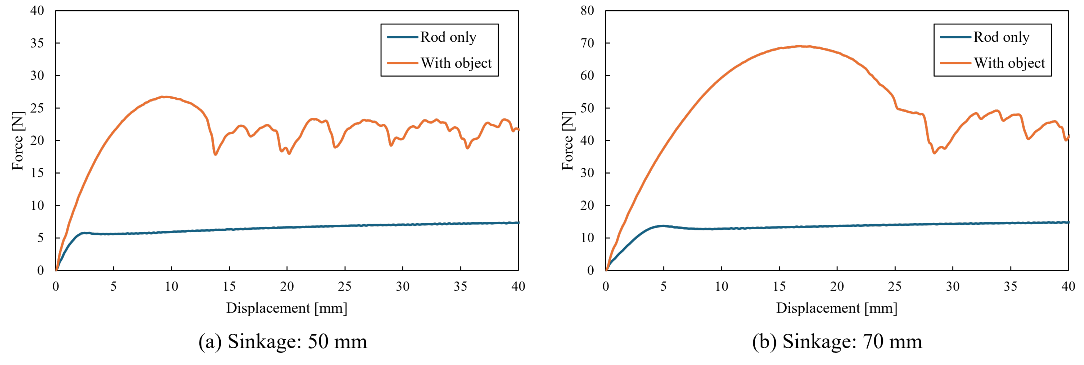
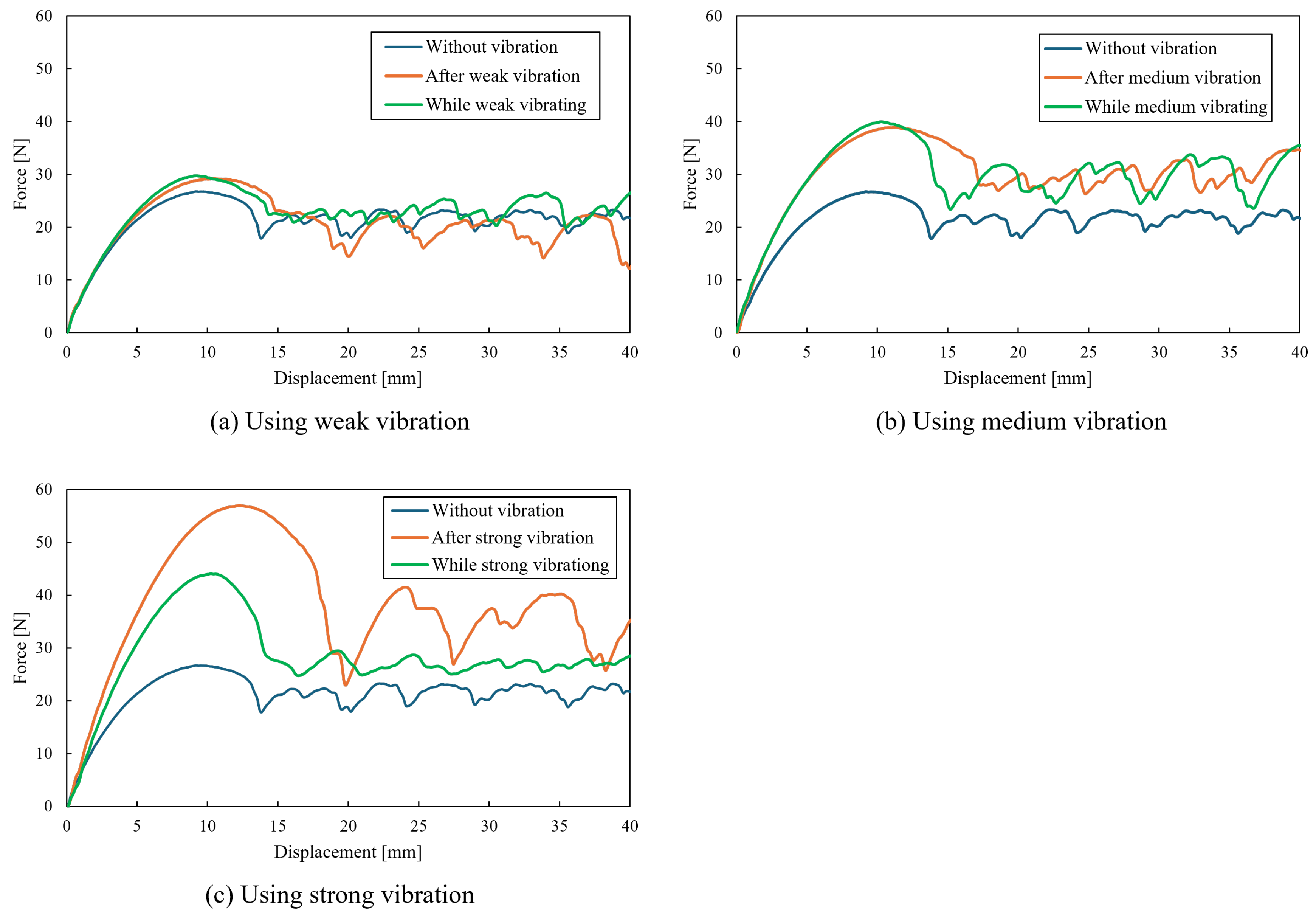
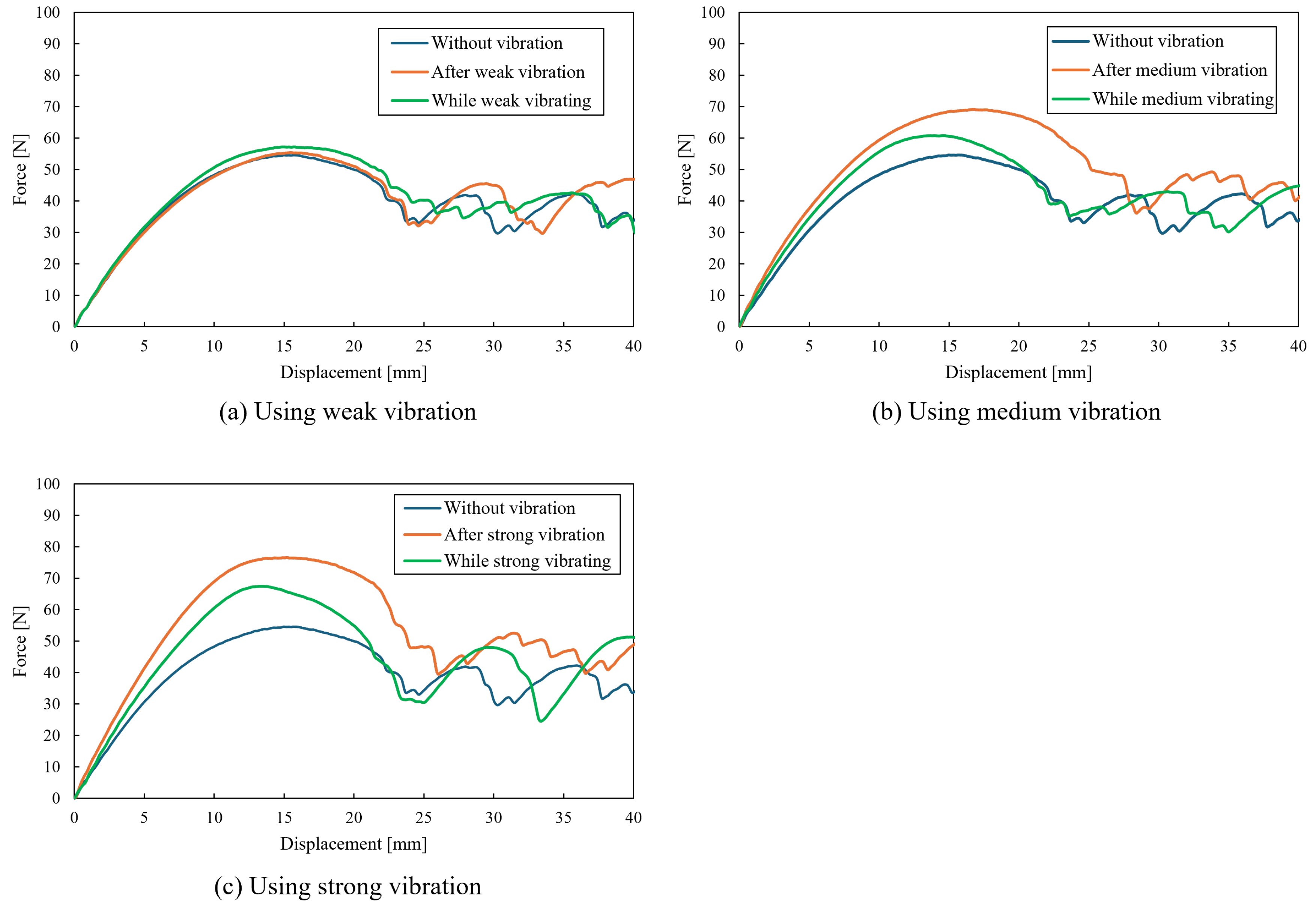
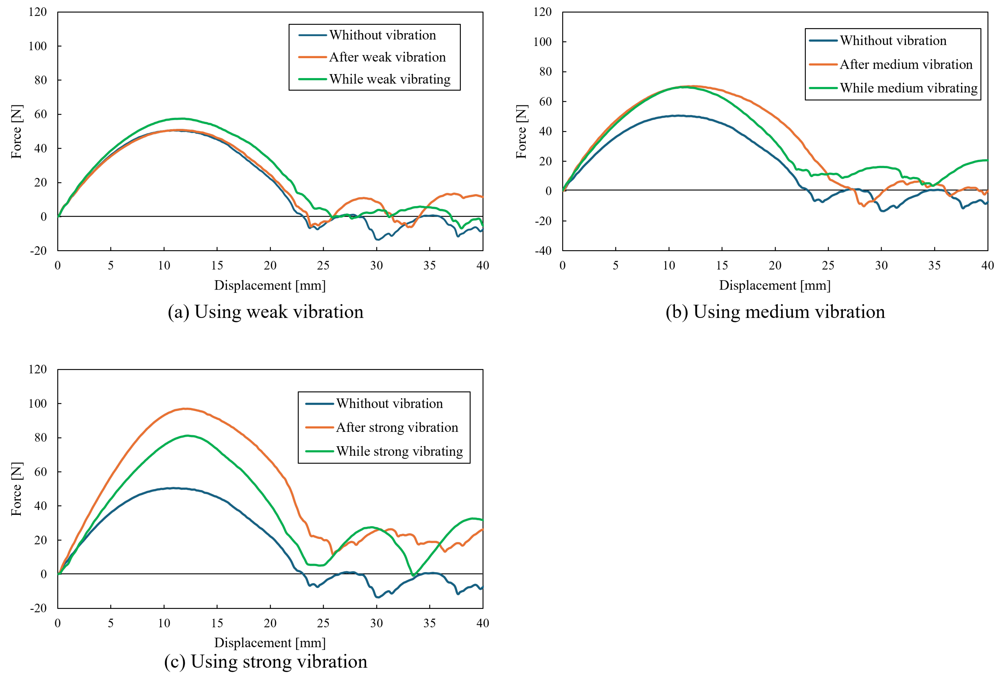
3.2.1. Drag Force Results

Figure 11 and Figure 12 show the variation in the drag force relative to shear displacement. The values represent the average of five trials.
Figure 11 shows the experimental results for the object sinkage of 50 mm. Figure 11a presents the results when weak vibration is imparted. When considering weak vibration, the drag force did not change based on how vibration was imparted because the values were almost consistent in each experimental condition. Figure 11b presents the results when using medium vibration. For medium vibration, the drag forces after vibration and while vibrating were larger than those without vibration. Figure 11c presents the results obtained when strong vibration was considered. For strong vibration, the drag force after vibration was the largest in each experimental condition, and that without vibration was the smallest in each experimental condition.
Figure 12 shows the experimental results for the object sinkage of 70 mm. When using weak and strong vibrations, the experimental results presented a similar tendency to that when the sinkage of the object was 50 mm (Figure 12a,c). Figure 12b presents the results when using medium vibration. For medium vibration, the drag force after vibration was the largest in each experimental condition, and the drag force without vibration was the smallest in each experimental condition.
Thus, an increase in the drag force affected by vibration depended on the vibration strength. The difference between the drag forces after and during vibration was expressed clearly when using strong vibration. The drag force after vibration was larger than that while vibrating. This phenomenon demonstrated that the drag force could be controlled based on the imparted vibration and considered for underground motion. Moreover, the deeper the sinkage of the object, the larger the drag force. This result suggests that the more profound the sinkage of the object, the more difficult it is to move underground. We considered that the limitation of the proposed underground moving method relates to the drag force.
The drag force increased with vibration because the area where ground particles moved with the object increased as the vibration compacted the ground. The area where ground particles moved with the object increased with increased ground density [29]. Our previous study confirmed that the area increased when imparting vibration using particle image velocimetry (PIV) [30]. The drag force while vibrating was smaller than that after vibration when using strong vibrations because the movement of ground particles was fluid-like. Baumgartner et al. investigated the movement of ground particles when imparting vibration to understand the movement of a sandfish skink, a lizard with the ability to move through desert sand [22]. They discovered that vibration rendered a local decompaction of the sand surrounding the vibrator, suggesting that high-frequency vibration caused the sand to behave like a fluid. Moreover, they confirmed a decrease in earth pressure by imparting high-frequency vibrations. The phenomenon was similar to the Janssen model [31], which explained the relationship between ground compaction and types of vibrations. In the Janssen model, the lift-off acceleration was defined. A critical acceleration caused the particles to separate and stay separated due to collisions. Figure 13 shows the relationship between particle movement and vibration acceleration. When the vibration acceleration was lower than lift-off acceleration, the particles remained in contact and moved with the object (Figure 13a). Then, the ground was compacted, and the drag force increased. When the vibration acceleration was higher than the lift-off acceleration, the particles separated because of collisions (Figure 13b). In this condition, the ground behaved like a fluid. According to the Janssen model, the condition could be explained by decompaction. The drag force decreased by decompacting the ground.

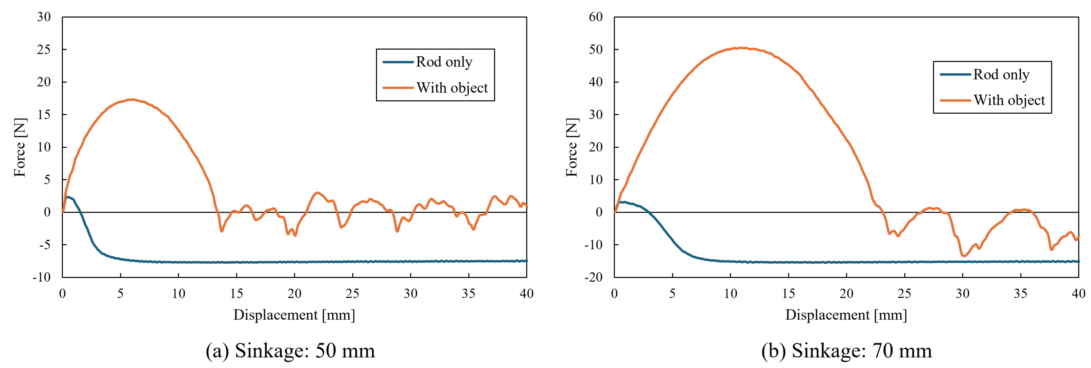
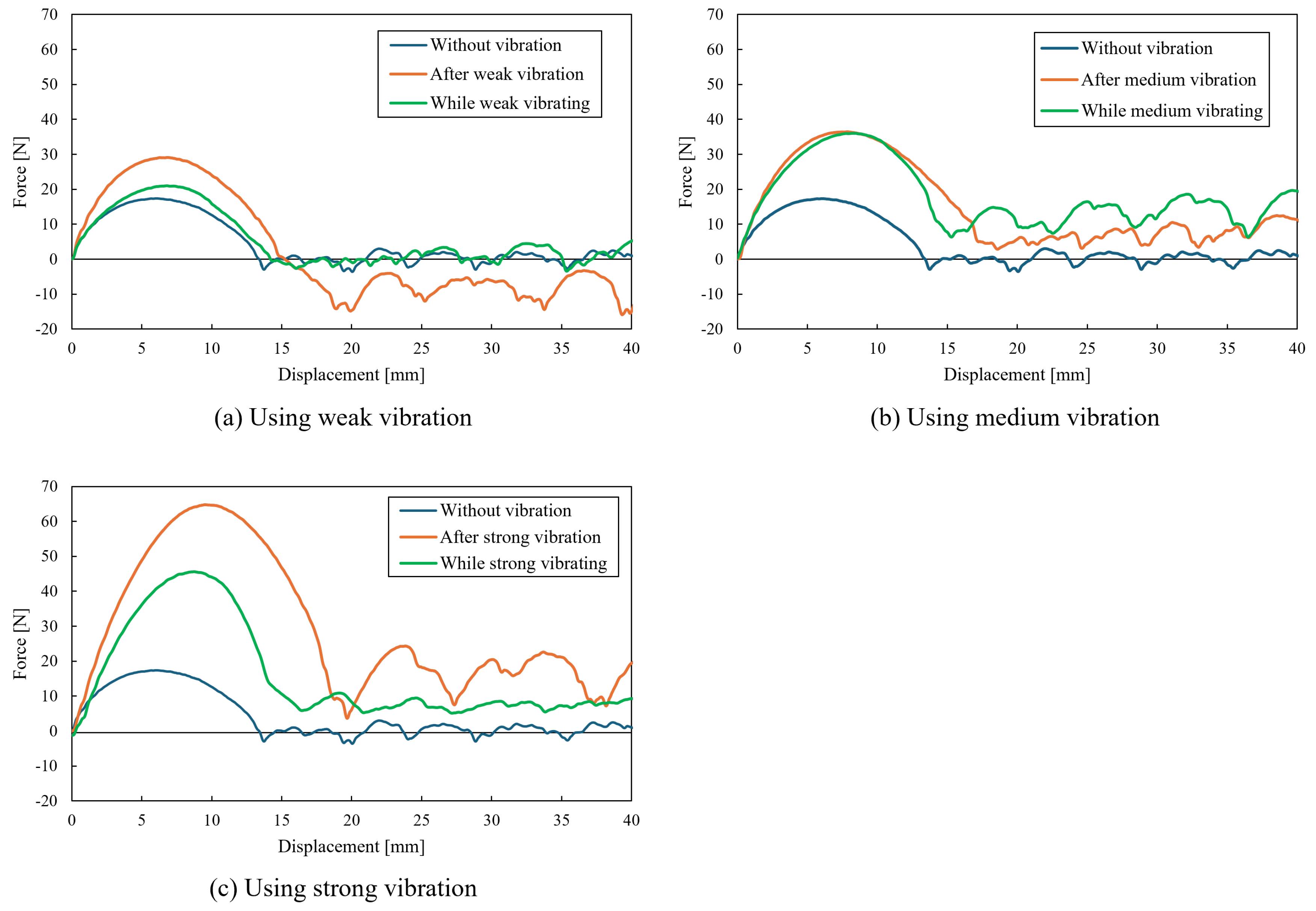
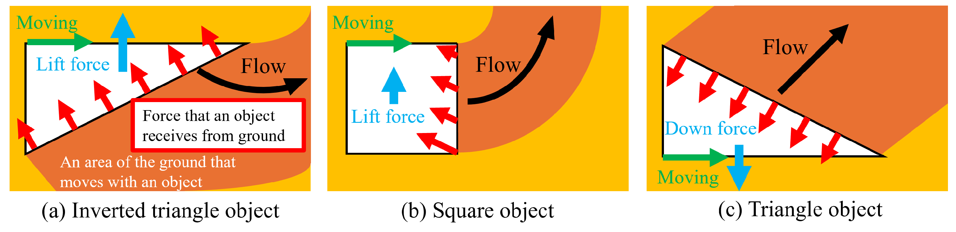
3.2.2. Lift Force Results

Figure 14 and Figure 15 show the lift force variations relative to shear displacement. The obtained values include the average of five trials.
Figure 14 shows the experimental results for the object sinkage of 50 mm. Figure 14a presents the results when using weak vibration. For weak vibration, the lift forces without vibration and while vibrating were almost the same. The lift force after vibration was the largest in each experimental condition. Figure 14b presents the results when using medium vibration. For medium vibration, the lift forces after vibration and while vibrating were larger than those without vibration. Figure 14c presents the results when using strong vibration. For strong vibration, the lift force after vibration was the largest in each experimental condition. Moreover, the lift force without vibration was the smallest in each experimental condition.
Figure 15 shows the experimental results for the object sinkage of 70 mm. When using weak vibration, the lift forces under all vibration conditions were almost the same (Figure 15a). When using medium vibration, the lift forces after vibration and while vibrating were almost the same (Figure 15b). The lift force without vibration was the smallest in each experimental condition. Figure 15c presents the results when using strong vibration. For strong vibration, the lift force after vibration was the largest in each experimental condition. Moreover, the lift force without vibration was the smallest in each experimental condition.
The lift force increased by imparting vibration in almost all experimental conditions. The phenomenon of the lift force altering by vibration was clearly expressed when using strong vibration. The lift force after vibration was larger than that while vibrating, which suggests that using vibration has a risk of making the robot move up easily when moving underground.
Ding et al. investigated the lift force produced when an object was pushed underground using an experiment and the discrete element method (DEM) simulation [32,33]. According to their experimental results, the value of the lift force was dependent on the tip angle of the object. Ding et al. confirmed that the object with a vertical tip angle to the pushing direction caused the lift force. The object shape was similar to that used in our experiment, and the results reported by Ding matched ours. Ding et al. considered that the value of the lift force was dependent on the movement of the ground particle when an object was pushed. The tip angle of the object changed the movement of the ground particle, as shown in Figure 16. The direction of the force received by the object surface from the ground changed according to the flow of ground particles.
The lift force increased due to vibration because the area where ground particles moved with the object increased as the vibration compacted the ground. We considered that the lift force when imparting vibration increased with the area where ground particles moved, as Ding et al. considered that the value of the lift force was dependent on this area.

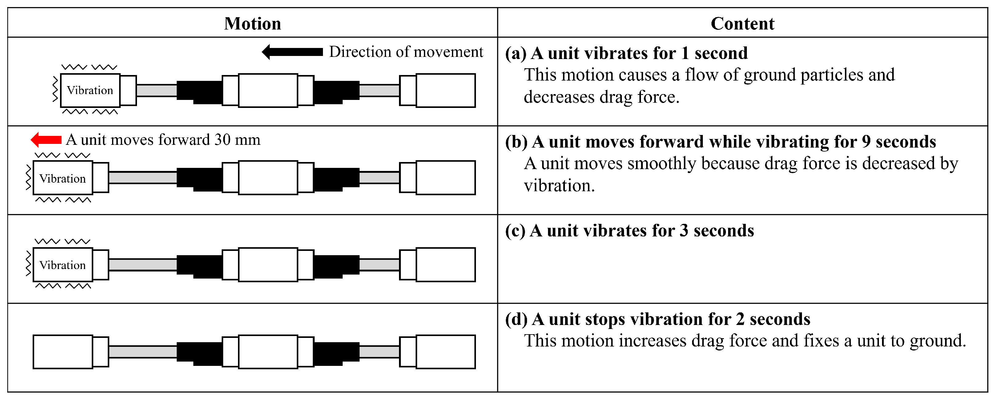
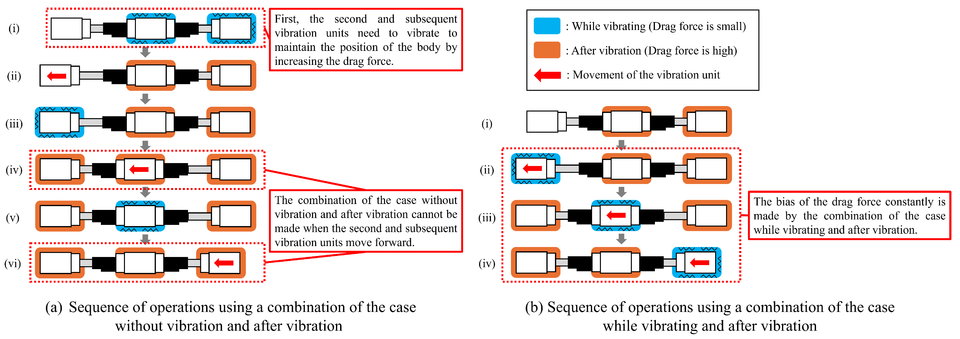
3.2.3. Proposal of Underground Motion Method Using Vibration

Section 3.2.1 showed that the value of the drag force is changed by how vibration is imparted. From this result, the testbed operation using vibrations is discussed. The proposed operation causes the bias of the drag force by imparting vibration and moves the vibration unit forward that receives the small drag force. The vibration unit, which moved forward, vibrated as it moved to decrease the drag force and enable smooth motion. The vibration unit stopped vibrating to increase the drag force and maintained the position and posture of the body. The vibration units moved forward one by one, with operational details for the forward motion of each unit shown in Figure 17. The vibration unit vibrated for 1 s to cause a flow of ground particles before starting the linear movement (Figure 17a). Next, the vibration unit moved forward while vibrating to decrease the drag force (Figure 17b). The distance and time of the linear operation were 30 mm and 9 s, respectively. The vibration unit vibrated for 3 s and then stopped the vibration for 2 s to increase the drag force after finishing the linear operation (Figure 17c,d). After completing these operations, they were repeated in the next rear unit. The first unit operations were conducted again after the operation of the last unit finished. The movement operation was defined as one cycle, from the first unit starting the operation to the last unit finishing one.
From the experimental results of Section 3.2.1, the bias of the drag force is the largest in the combination of the case without vibration and after vibration. However, the combination of the case without vibration and after vibration cannot be made constantly. For example, when the front unit moves forward, the center and rear units need to make a compacted ground condition by imparting vibration (Figure 18a (i) and (ii)). When the center unit moves forward (Figure 18a (iv)), the ground around the center unit is compacted by vibration in the previous operation (Figure 18a (i)). Therefore, the combination of the case without vibration and after vibration cannot be made when the second and subsequent vibration units move forward because they are in the compacted ground by imparting vibration in the previous operation. This study proposed the operation that constantly makes the bias of the drag force with the combination of the cases of while vibrating and after vibration, as shown in Figure 18b.

4. Verification of the Underground Motion Method

As described in Section 3, we confirmed that the ground conditions changed with vibration and proposed the underground motion method, considering the discussed phenomenon. In this section, we detail our experiments wherein the testbed moved underground using the proposed testbed in Section 2.3. The mobility of the testbed was evaluated based on the experimental results.

4.1. Experimental Methods

The experimental environment comprised a soil tank and testbed (Figure 19). The sand in the soil tank was Toyoura sand. The experimental flow is explained. First, the testbed sank 100 mm into the ground. The ground’s shear strength was measured using a hand vane before conducting all experiments to confirm the ground conditions. The values of shear strength, which were measured in all experiments, ranged from 0.30 cN·m to 0.49 cN·m. Therefore, we consider that the experimental ground conditions remained constant. The maker was attached to each vibration unit to measure the body position. The makers were on the ground during the experiment. The movement operated in 20 cycles. The position information in the x and z directions, as shown in Figure 19, was measured using Kinovea (Version 2023.1, It is created by Joan Charmant.), the motion analysis software, from the movie that recorded the experiment. A calibration object, shown in Figure 19, was used for fitting the pixel size and real size in Kinovea. Two movement patterns with and without vibration were prepared. Strong vibration was used in the movement because the drag force changed significantly, as confirmed in Section 3.2.1. Five trials were performed for each experimental condition. Table 4 presents the experimental conditions.

4.2. Experimental Results and Discussion

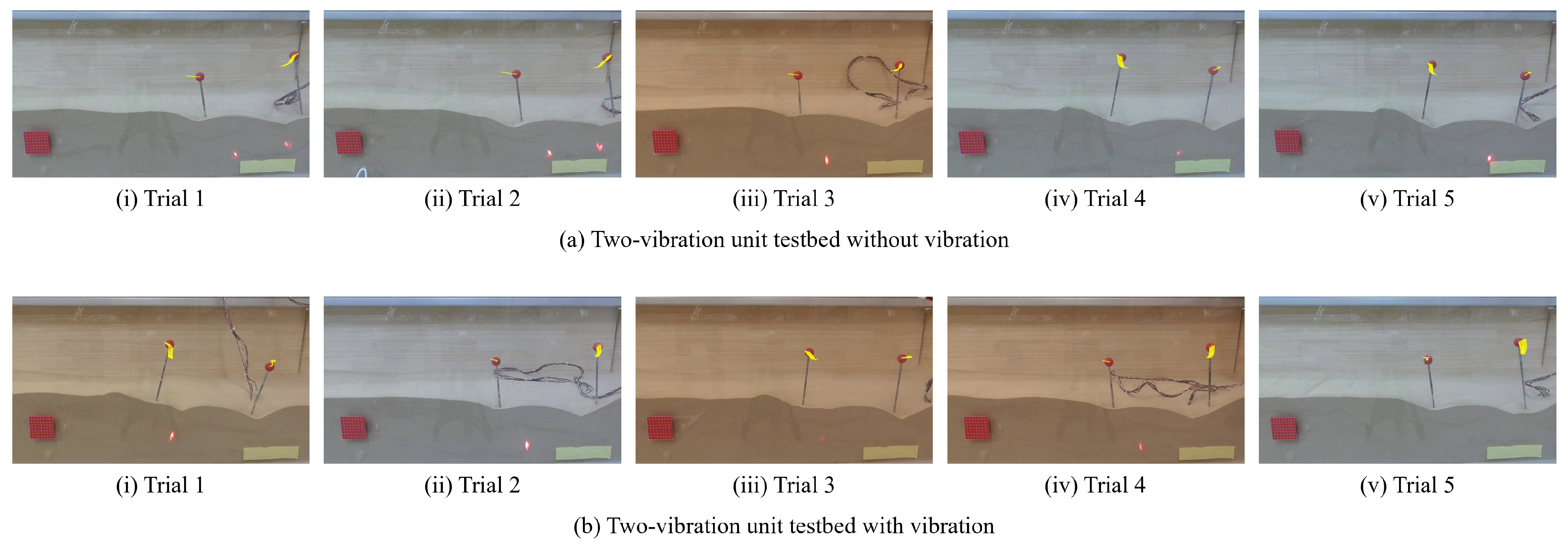
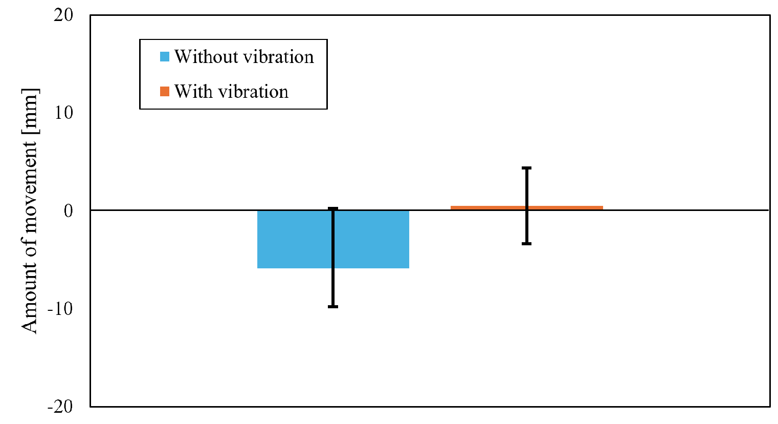
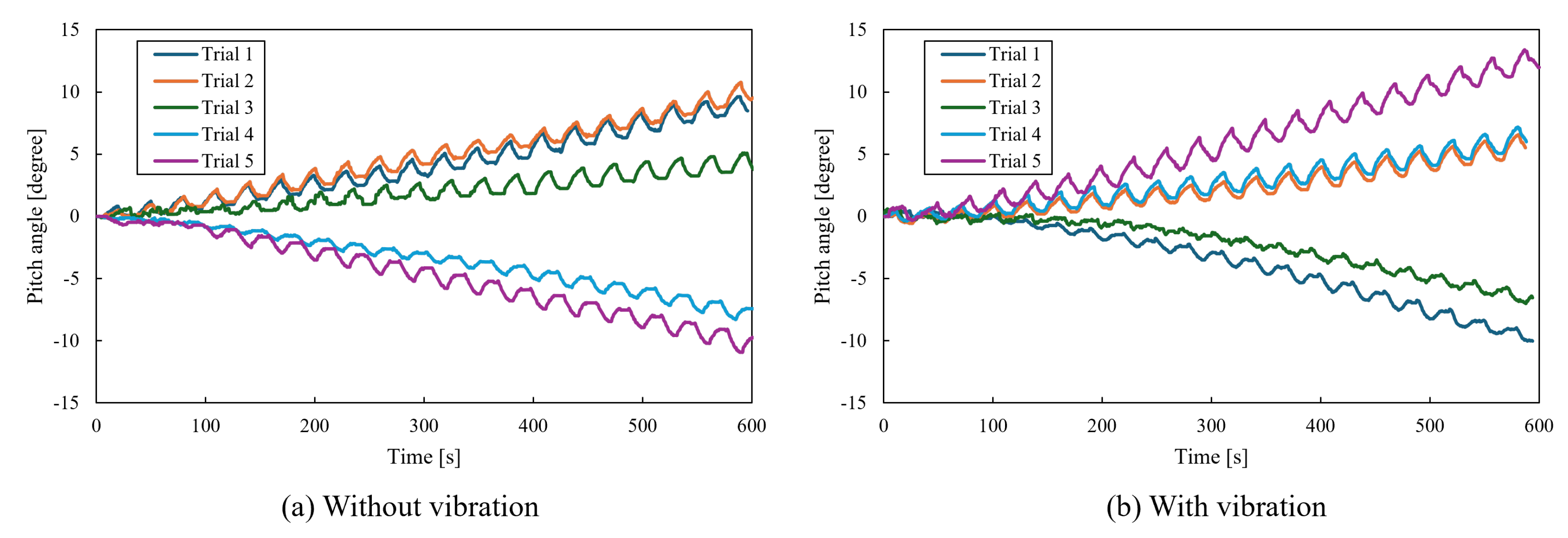
4.2.1. Results for Two-Vibration Unit Testbed

The experimental results obtained using a two-vibration unit testbed are explained. Figure 20 shows the marker movement trajectory in each experiment. The yellow lines are the movement trajectory of the vibration unit. Figure 21 shows the movement extent of the testbed under each experimental condition. The two-vibration unit testbed moved back when it operated without vibration. The two-vibration unit testbed almost did not move when it operated with vibration. The testbed did not move forward with or without vibration, as shown in Figure 20 and Figure 21. The front or rear unit lifted in almost all trials. Figure 22 shows the pitch angle of the testbed, calculated from the positions of the front and rear units. The pitch angle changed by approximately 10° in almost all trails because the lift force increased when the vibration unit moved. This result indicates that the two-vibration unit testbed cannot maintain its posture when moving underground. The reason that the testbed cannot maintain its posture is considered. In the experiment, the front or rear unit was fixed, and the other unit moved forward and backward. Therefore, the testbed did not move forward overall. The forward and backward movement of the unit generated a lift force, causing the moving unit to be lifted. For this reason, we consider that the posture of the two-vibration unit testbed was changed significantly.

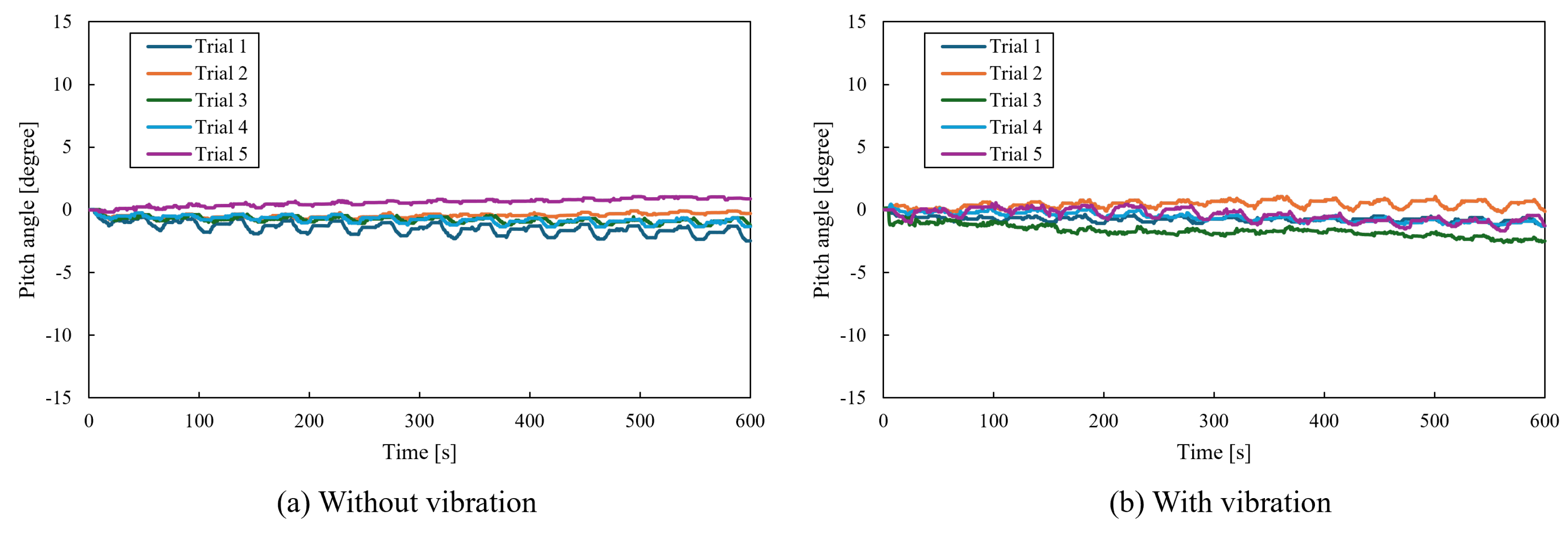
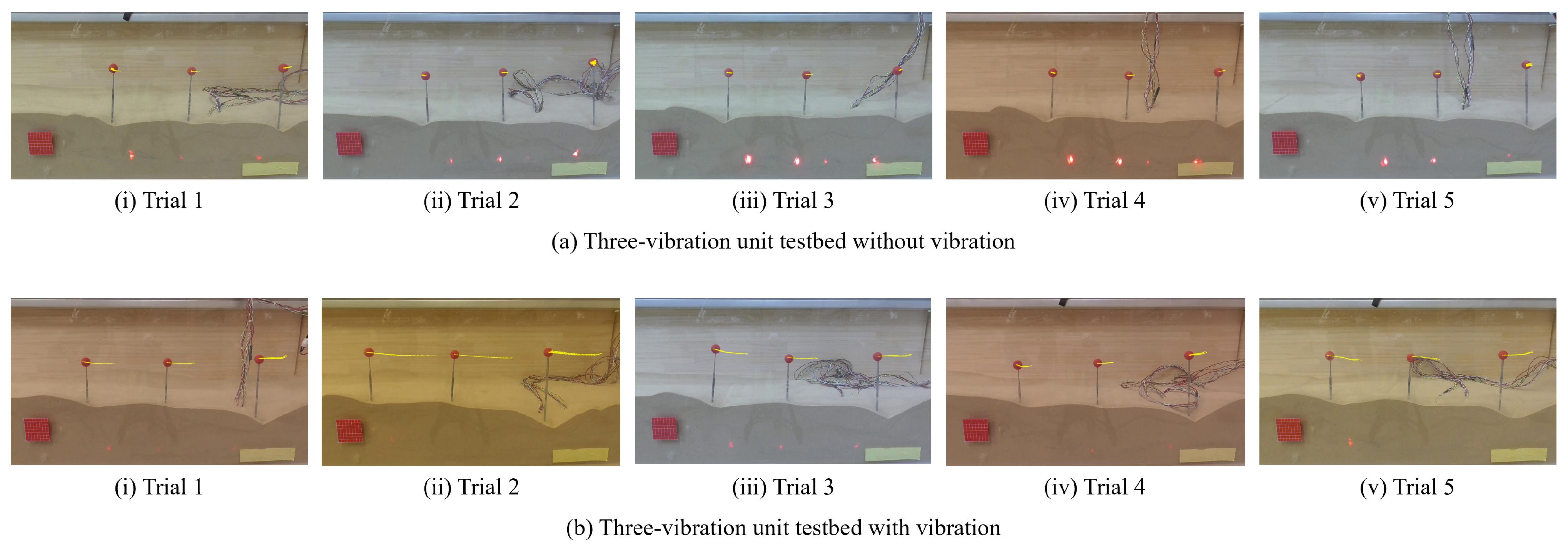
4.2.2. Results for the Three-Vibration Unit Testbed

The experimental results obtained using the three-vibration unit testbed are explained here. Figure 23 shows the pitch angle of the testbed, calculated from the front and center unit positions. The pitch angle changed within 3° in all trials and barely changed, as shown in Figure 23. This result indicates that the three-vibration unit testbed can maintain its posture when moving underground. This is because the two stationary vibration units maintained the posture of the testbed against the lift force caused by the moving unit. From the experimental results, using the two- and three-vibration unit testbed, the construction of the testbed (number of the vibration units) is more dominant in determining the changes in the pitch angle than the vibration effect. Figure 24 shows the marker movement trajectory in each experiment. Figure 25 shows the movement extent of the testbed under each experimental condition. The testbed with vibration moved forward compared to the one without vibration, as shown in Figure 24 and Figure 25. To compare the results of the two-vibration unit testbed (Section 4.2.1), the movement extent for the three-vibration unit testbed moving with vibration was the longest because the two stationary vibration units fixed to the ground prevented the testbed from slipping when the remaining vibration unit moved. We confirmed that the proposed movement and testbed efficiently used the changing ground conditions due to vibration because the movement extent with vibration was longer than that without vibration.

4.2.3. Investigation of Relationship between Mobility and Strength of Vibration

The phenomenon of changing the drag force by vibration is related to the vibration type (see Section 3.2.1). The experimental results detailed in Section 4.2.2 show that the proposed method, which uses vibration, is effective for underground motion. This section reports the mobility of the underground movement method for different vibration types. A three-vibration unit testbed was used in this investigation. Weak and medium vibrations, as listed in Table 2, were used. The experimental environment and flow are the same as those described in Section 4.1.
Figure 26 shows the marker movement trajectory in each experiment. Figure 27 shows the movement extent of the testbed in each vibration. The results using strong vibration, which is shown in Figure 27, were measured as described in Section 4.2.2. This result suggests that the greater the vibration used, the longer the movement. As explained in in Section 3.2.1, we confirmed that the greater the vibration, the greater the difference in the drag force while vibrating and after vibration. Based on these experimental results, the movement extent of the testbed becomes longer using vibration, which is a strong vibration because a significant difference in the drag force is observed while vibrating and after vibration. Therefore, a relationship exists between the vibration type and mobility of the underground movement.

4.2.4. Discussion of Slip Rate

The experimental results in Section 4.2.2 confirm that the proposed method can achieve underground motion using the phenomenon of varying ground conditions due to vibration. The slip rate of the three-vibration unit testbed with vibration is calculated from the movement extent when the testbed moves with vibration, using Equation (1). L i is the ideal movement extent when the testbed does not slip. L i is 600 mm, which is obtained by the length of the linear actuator extending (30 mm) times 20 cycles of movement. L m is the measured movement amount using strong vibration and is 68 mm. From these values, the slip rate is calculated as 88.6%. The smaller the slip rate, the more the testbed does not slip. The proposed method can be expected to potentially improve mobility performance because the shape and number of the vibration units and the proposed movement have been considered in the initial stages of this study. The relationship between vibrational changes in the ground and these parameters must be investigated in future studies to improve the proposed underground movement method.
s = 100 × ( L i L m L i )

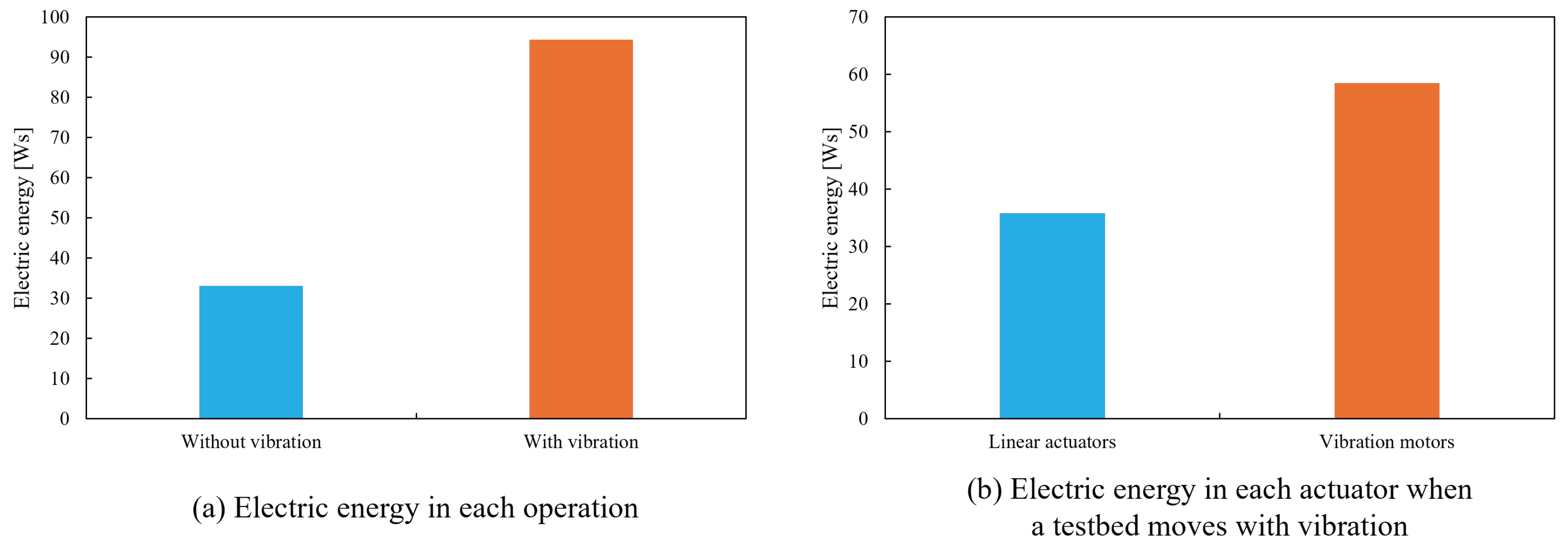
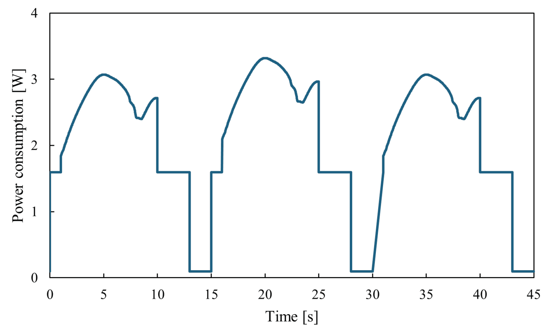
4.2.5. Discussion of Energy Efficiency

The electric energy of the three-vibration unit testbed was compared without vibration and with strong vibration. The electric energy of the vibration motor P v [Ws] was calculated using Equation (2). E v [V] and I v [A] are the voltage and electric current supplied to the vibration motor, respectively. T v [s] is the duration for which the vibration occurs. E v was set to 30 V. We confirmed that I v was 0.05 A when E v was set to 30 V.
P v = 0 T v E v × I v d t
The electric energy of the linear actuator P l [Ws] was calculated from Equation (3). E l [V] and I l [A] are the voltage and electric current supplied to the linear actuator, respectively. T l [s] is the duration for which the linear actuator moves. E l was set to 6.6 V. I l showed 0.0072 A as standby current when the linear actuator does not move. I l is calculated using Equation (4) when the linear actuator moves. Equation (4) was obtained from the datasheet of the linear actuator (L12-30-210-S).
P l = 0 T l E l × I l d t
I l = 2.75 × 10 3 F l + 0.045
F l [N] is the load on the linear actuator and is changed by extending the linear actuator. The value of F l was set to be the change in the experimental result shown in Figure 12c. The experimental result without vibration was used as the value of F l when the testbed moves without vibration, while that with strong vibrating was used as the value of F l when the testbed moves with vibration.
Figure 28a compares the electric energy of the testbed without and with vibration to conduct one cycle of an operation for moving underground. The electric energy with vibration is 2.86 times that without. Figure 28b shows the electric energy of the vibration motors and linear actuators when the testbed moves with vibration. As shown in Figure 28b, the electric energy of the vibration motors is 1.63 times that of the linear actuators. These results indicate that electric energy with vibration is larger than without vibration because the vibration motors consume more electric power than the linear actuators. Therefore, the electric energy consumed by the vibration motor needs to be reduced so as to reduce the testbed’s energy consumption. The proposed movement of the testbed is in the initial stage. Elucidating the relationship between vibration and the testbed’s mobility can make it possible to reduce the testbed’s electric energy consumption by selecting a suitable vibration strength and time.
The proposed method’s practicality in extraterrestrial bodies is discussed. Figure 29 shows the assumed power consumption of the testbed to conduct one cycle of the proposed operation for moving underground with vibration. The maximum value of power consumption was 3.32 W. Table 5 shows the specifications of the solar panel attached to SLIM [34]. We selected this information because SLIM reached the Moon in January 2024. One plate of this solar panel generates 20.9 W. Therefore, this information suggests that the current-generated electric system for use in extraterrestrial bodies can cover the power consumption of the testbed.

5. Conclusions

This study proposed a method for underground motion, considering changing ground conditions due to vibration. First, the force that an object receives from the ground is measured when the object vibrates to confirm the effectiveness of using vibration to move underground. We investigated the changes in the drag and lift forces based on how vibration is imparted, as understanding this relationship is useful for underground motion. In the experiments, the forces were measured when a vibrating object was pushed on the ground. The experimental results suggest that the drag force changed depending on how vibrations were imparted. The drag force after vibration was larger than that while vibrating. This phenomenon shows that the drag force can be controlled depending on how vibration is imparted and is considered helpful for underground motion. The lift force demonstrated a similar tendency to the drag force. Further, the underground movement method was proposed based on varying ground conditions with vibration. In the experiment, a testbed was constructed based on the proposed method. Experiments were conducted on the testbed moving underground. Finally, the mobility of the testbed was evaluated based on the experimental results. The testbed, comprising three vibration units, moved forward using vibration. Thus, the proposed movement and testbed efficiently used the varied ground conditions. The testbed, comprising three vibration units, did not lift to the surface of the ground owing to the two stationary vibration units, which maintained the posture of the testbed against the lift force due to the moving vibration unit. From experimental results, the number of vibration units is more dominant for maintaining the posture of the testbed than the vibration effect. Moreover, the greater the vibration used, the longer the forward distance moved by the testbed. This is because increasing vibration increases the difference in drag force while vibrating and after vibration. Therefore, the mobility of the proposed underground movement method is related to the vibration intensity. These insights are thus valuable for underground rover construction. This study suggests a method to facilitate further planetary underground exploration.
The proposed testbed slips and consumes significant electricity. Therefore, the method can potentially improve mobility performance and energy efficiency because the shape and number of the vibration units and the proposed movement were considered in the initial stages of this study. Moreover, changes in ground conditions will be investigated by using different kinds of sand. The proposed method can be improved by investigating the relationship between changes in ground conditions due to vibration and these parameters in future studies.

Author Contributions

T.W. wrote the manuscript as the corresponding author. He and K.K. also developed the experimental setup and performed experiments. K.H. and K.I. supervised the entire study. All authors have read and agreed to the published version of the manuscript.

Funding

This research was funded by JSPS KAKENHI Grant Number JP 23K13296.

Informed Consent Statement

Not applicable.

Data Availability Statement

The raw data supporting the conclusions of this study will be made available by the authors on request.

Conflicts of Interest

The authors declare no conflicts of interest.

Abbreviations

The following abbreviations are used in this manuscript:
NASANational Aeronautics and Space Administration
ISROIndian Space Research Organisation
JAXAJapan Aerospace Exploration Agency
LUPEXLunar Polar Exploration Mission
MMXMartian Moons eXploration
UGVUnmanned Ground Vehicle
SLIMSmart Lander for Investigating Moon
GPRGround Penetrating Radar
LPRLuna Penetrating Radar
DEMDiscrete Element Method
NMRNuclear Magnetic Resonance
PIVParticle Image Velocimetry
RPSRotations Per Second

Appendix A. Measurement of the Ground Forces with Rod Only

The conditions in the investigation described in Section 3 were slightly different from the actual conditions. In the experiment in Section 3, the rod connected the force sensor and received force from the ground. The measured drag and lift force values included the force that the rod received. To evaluate the rod’s influence on these forces, they were measured with the rod only.
The experimental setup was the same as that detailed in Section 3.1 (Figure 9). It comprised a soil tank, rod, and force sensor. The shape of the rod is a square prism. The cross-section of the rod was square, with sides of 10 mm. Next, the experimental procedure is explained. Initially, ground soil was mixed and flattened, after which a rod was positioned on the ground with a sinkage of 50 and 70 mm. The ground’s shear strength was measured using a hand vane before conducting all experiments to confirm the ground conditions. The shear strength values, which were measured in all experiments, ranged from 0.38 cN·m to 0.44 cN·m. Therefore, we consider that the experimental ground conditions remain constant. Further, the object was pushed, and the drag and lift force values were measured using the force sensor. The rod was moved at a speed of 4.17 mm/s and pushed for 10 s. Each experimental condition was tested over five trials. The experimental conditions are the same as those mentioned in Section 3.1 (Table 3).
Figure A1 and Figure A2 show the variations in the drag and lift forces relative to shear displacement. The values represent the average of five trials. The forces in a rod only were smaller than with an object. Table A1 shows the maximum value of the ground forces under each experimental condition. The drag forces in a rod only were below 30% of those with an object. The lift forces in a rod only were below 15% of those with an object. From these experimental results, we consider that the rod’s influence on these forces is small.
Pushing the object underground using a horizontal linear actuator instead of pushing the rod would likely help to avoid the influence of the rod and present a clearer picture of what is happening. In future studies, such experiments will be conducted.
Figure A1. Drag force versus shear displacement. Drag force using a rod only is compared with that with an object.
Aerospace 11 00811 g0a1
Figure A2. Lift force versus shear displacement. Lift force using a rod only is compared with that with an object.
Aerospace 11 00811 g0a2
Table A1. Maximum values of ground forces under each experimental condition.
Experimental ConditionForce in a Rod Only [N]Force with an Object [N]
Drag force, sinkage of a rod: 50 mm7.3626.7
Drag force, sinkage of a rod: 70 mm14.869.1
Lift force, sinkage of a rod: 50 mm2.3617.3
Lifr force, sinkage of a rod: 70 mm3.1950.5

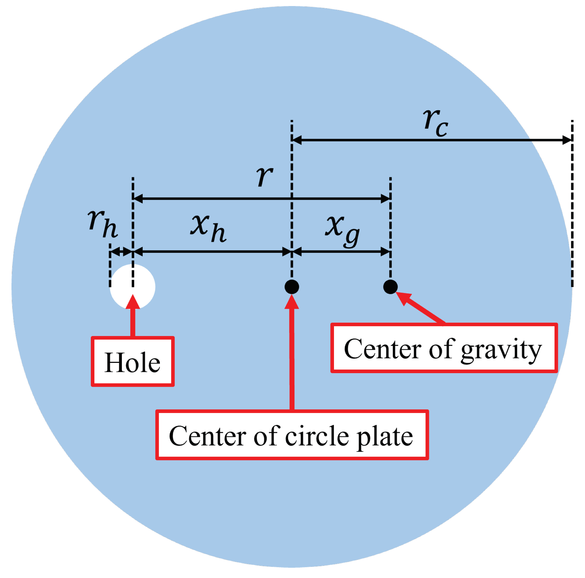
Appendix B. Measurement of Vibration Parameters

The measurement and calculation of vibration parameters are explained here.
First, the vibration frequency is explained. The encoder was attached to the axis of the vibration motor, and the rotations per second (RPS) was measured by oscilloscope. The vibration frequency is defined as RPS because one rotation of the vibration motor generates one vibration wave. The vibration frequency was measured over five trials.
Next, the vibration force is explained. The vibration force is defined as the centrifugal force generated by the unbalanced load. We considered that the unbalanced load is the mass point and calculated the vibration force F v [N] from Equation (A1). m [kg] and r [m] are the mass and rotation radius of the unbalanced load, respectively. ω [rad/s] is the rotation speed.
F v = m r ω 2
Figure A3 and Table A2 show the shape and specifications of the unbalanced load, respectively. The shape of the unbalanced load is a circle plate. The circle plate has a hole to connect to the rotation axis of the vibration motor. r is calculated from Equation (A2).
r = x g + x h
x g is calculated from Equation (A3). Equation (A3) is obtained from equilibrium of moment.
x g = r h 2 r c 2 r h 2 x h
ω is calculated from Equation (A4). f is the vibration frequency.
ω = 2 π f
Figure A3. Shape of an unbalanced load.
Aerospace 11 00811 g0a3
Table A2. Specifications of an unbalanced load.
ParameterValue
Distance from center of circle plate to center of gravity x g 0.899 × 10 4 [m]
Distance from center of circle plate to center of hole x h 2.70 × 10 3 [m]
Radius of hole r h 1.05 × 10 3 [m]
Radius of circle plate r c 5.85 × 10 3 [m]
Rotation radius of an unbalanced load r 2.79 × 10 3 [m]
Mass of an unbalanced load m 2 × 10 3 [kg]

References

  1. Wang, T.; Quan, Q.; Xu, Y.; Yu, H.; Tang, D.; Deng, Z. Study the influence of anchoring parameters on asteroid drilling anchoring with discrete element simulation. Adv. Spa. Res. 2023, 71, 816–828. [Google Scholar] [CrossRef]
  2. Hein, M.A.; Matheson, R.; Fries, D. A techno-economic analysis of asteroid mining. Act. Astr. 2020, 168, 104–115. [Google Scholar] [CrossRef]
  3. Sommariva, A.; Gori, L.; Chizzolini, B.; Pianorsi, M. The economics of moon mining. Act. Astr. 2020, 170, 712–718. [Google Scholar] [CrossRef]
  4. Qiao, L.; Chen, J.; Xu, L.; Wan, S.; Cao, H.; Li, B.; Ling, Z. Geology of the Chang’e-5 landing site: Constraints on the sources of samples returned from a young nearside mare. Icarus 2021, 364, 114480. [Google Scholar] [CrossRef]
  5. Liu, J.; Liu, B.; Ren, X.; Li, C.; Shu, R.; Guo, L.; Yu, S.; Zhou, Q.; Liu, D.; Zeng, X.; et al. Evidence of water on the lunar surface from Chang’E-5 in-situ spectra and returned samples. Nat. Commun. 2022, 13, 3119. [Google Scholar] [CrossRef]
  6. NASA, MARS. 2020 Mission Perseverance Rover. Available online: https://mars.nasa.gov/mars2020/mission/overview/ (accessed on 26 August 2024).
  7. JAXA, International Space Exploration, Lunar Polar Exploration (LUPEX). Available online: https://www.exploration.jaxa.jp/e/program/lunarpolar/index.html (accessed on 26 August 2024).
  8. JAXA, International Space Exploration, Martian Moons eXploration (MMX). Available online: https://www.exploration.jaxa.jp/e/program/index.html#mmx (accessed on 26 August 2024).
  9. Touhoku University, Startup Incubation Center. Available online: https://startup.tohoku.ac.jp/achievement/interview-kisuitech/ (accessed on 26 August 2024).
  10. JAXA, International Space Exploration, Smart Lander for Investigating Moon (SLIM). Available online: https://www.exploration.jaxa.jp/e/program/index.html#slim (accessed on 26 August 2024).
  11. NASA, Gateway. Available online: https://www.nasa.gov/mission/gateway/ (accessed on 26 August 2024).
  12. JAXA, Hayabusa2 Extended Mission. Available online: https://www.hayabusa2.jaxa.jp/en/ (accessed on 26 August 2024).
  13. NASA, Weather on the Moon. Available online: https://science.nasa.gov/moon/weather-on-the-moon/ (accessed on 26 August 2024).
  14. Notsu, R.; Nagano, H.; Ogawa, H. A proposal of lunar long duration method (Fabrication of lunar environment simulator and experimental validation). Tran. JSME 2014, 80, TEP0199. [Google Scholar] [CrossRef]
  15. Nakatake, T.; Konno, M.; Mizushima, A.; Yamada, Y.; Nakamura, T.; Kubota, T. Soil-Circulating System for a Peristaltic-Type Lunar Excavation Robot. J. Rob. Soc. Jpn. 2017, 35, 230–238. [Google Scholar] [CrossRef]
  16. Nicholas, D.N.; Karsai, A.; Cooper, M.M.; Aydin, O.Y.; Aydin, E.; Goldman, I.D.; Hawkes, W.E. Controlling subterranean forces enables a fast, steerable, burrowing soft robot. Sci. Robot. 2021, 6, eabe2922. [Google Scholar] [CrossRef]
  17. Nesnas, A.D.I.; Kerber, L.; Sellar, G.; Balint, T.; Denevi, B.; Parness, J.A.; Kornfeld, P.R.; Smith, M.; McGarey, P.; Brown, T.; et al. Moon Diver: Exploring a pit’s exposed strata to understand lunar volcanism. Act. Astr. 2023, 211, 163–176. [Google Scholar] [CrossRef]
  18. Yuan, Z.; Mu, R.; Zhao, H.; Wang, K. Predictive Model of a Mole-Type Burrowing Robot for Lunar Subsurface Exploration. Aerospace 2023, 10, 190. [Google Scholar] [CrossRef]
  19. Winter, G.A.; Deits, H.L.R.; Dorsch, S.D.; Slocum, H.A.; Hosoi, E.A. Razor clam to RoboClam: Burrowing drag reduction mechanisms and their robotic adaptation. Bioinspir. Biomim. 2014, 9, 036009. [Google Scholar] [CrossRef] [PubMed]
  20. Cerkvenik, U.; Dodou, D.; Leeuwen, L.J.; Gussekloo, S.W.S. Functional principles of steerable multi-element probes in insects. Bio. Rev. 2019, 94, 555–574. [Google Scholar] [CrossRef] [PubMed]
  21. Watanabe, T.; Iizuka, K. Proposal of walking to reduce slipping behavior using compaction effect of loose soil caused by a propagation of vibration for small light lunar planetary exploration rovers with legs. Trans. JSME 2020, 86, 886. [Google Scholar] [CrossRef]
  22. Baumgartner, W.; Fidler, F.; Weth, A.; Habbecke, M.; Jakob, P.; Butenweg, C.; Bohme, W. Investigating the Locomotion of the Sandfish in Desert Sand Using NMR-Imaging. PLoS ONE 2008, 3, e3309. [Google Scholar] [CrossRef] [PubMed]
  23. Watanabe, T.; Iizuka, K. Experimental investigation of relationship between bearing capacity and vibration parameters for planetary exploration legged rovers. ROBOMECH J. 2023, 10, 27. [Google Scholar] [CrossRef]
  24. Yeomans, B.; Saaj, M.C.; Winnendael, V.M. Walking planetary rovers - Experimental analysis and modelling of leg thrust in loose granular soils. J Terramech. 2013, 50, 107–120. [Google Scholar] [CrossRef]
  25. King, H.R.; Susante, V.P.; Gefreh, A.M. Analytical models and laboratory measurements of the soil-tool interaction force to push a narrow tool through JSC-1A lunar simulant and Ottawa sand at different cutting depths. J. Terramech. 2011, 48, 85–95. [Google Scholar] [CrossRef]
  26. Kobayashi, T.; Fujiwara, Y.; Yamakawa, J.; Yasufuku, N.; Omine, K. Mobility performance of a rigid wheel in low gravity environments. J. Terramech. 2010, 47, 261–274. [Google Scholar] [CrossRef]
  27. Ono, S.; Namikawa, S.; Yoshida, K. Analysis of soil flow and traction mechanics for lunar rovers over different types of soils using particle image velocimetry. J. Terramech. 2021, 95, 89–100. [Google Scholar] [CrossRef]
  28. Oe, A.; Nishida, S.; Nakatani, S. Study of passive steering mechanism for small Mars surface exploration rovers. J. Terramech. 2024, 112, 35–43. [Google Scholar] [CrossRef]
  29. Wada, S.; Kouda, M.; Enami, A. Experimental study on passive earth pressure Part 1 The experimental device and an example of the passive earth pressure tests by the device. J. Str. Con. Eng. Arc. Ins. Japan 1998, 63, 69–76. [Google Scholar] [CrossRef]
  30. Watanabe, T.; Iizuka, K. Observation of Movement of Ground Particles Given Vibration When Rod Is Dragged. Int. J. Eng. Technol. 2022, 14, 1–8. [Google Scholar] [CrossRef]
  31. Arnold, N.E. Identifying the effects of history on adaptation: Origins of different sand-diving techniques in lizards. J. Zoo. 1995, 235, 351–388. [Google Scholar] [CrossRef]
  32. Ding, Y.; Gravish, N.; Goldman, I.D. Drag Induced Lift in Granular Media. Phys. Rev. Lett. 2011, 106, 028001. [Google Scholar] [CrossRef] [PubMed]
  33. Maladen, D.R.; Umbanhowar, B.P.; Ding, Y.; Masse, A.; Goldman, I.D. Granular lift forces predict vertical motion of a sand-swimming robot. In Proceedings of the 2011 IEEE International Conference on Robotics and Automation, Shanghai, China, 9–13 May 2011. [Google Scholar] [CrossRef]
  34. SAHRP, News Release, January 2024. Available online: https://corporate.jp.sharp/news/240129-b.html (accessed on 26 August 2024).
Figure 1. Overview of the plan for an underground exploration mission.
Aerospace 11 00811 g001
Figure 2. Overview of forces in the ground.
Aerospace 11 00811 g002
Figure 3. Underground movement of a razor clam referred to from [19]. (a) First, the razor clam expands its body and compacts the ground using its shell. Then, it fixes the shell to the ground because significant friction occurs in the shell due to motion. (b) Next, it extends a foot in the forward direction. (c) It expands to serve as an anchor. (d) Finally, the razor clam releases the shell compaction and shrinks its foot length to move forward.
Aerospace 11 00811 g003
Figure 4. Underground movement of an earthworm referred to from [15]. (a) Structure of an earthworm. (b) The second segment expands to fix to the ground, and the first and third segments shrink to move forward. (ce) Expanded and shrank segments are selected from the rear segments, which were expanded and shrank in previous operations. Finally, the body of the earthworm moves forward.
Aerospace 11 00811 g004
Figure 5. Penetration movement of a wasp’s ovipositor referred to from [20].
Aerospace 11 00811 g005
Figure 7. Overview and construction of testbeds.
Aerospace 11 00811 g007
Figure 8. Shape of the vibration unit and the vibration direction.
Aerospace 11 00811 g008
Figure 9. Experimental environment for measuring the forces in the ground.
Aerospace 11 00811 g009
Figure 10. Experimental flow for measuring the forces in the ground.
Aerospace 11 00811 g010
Figure 11. Drag force versus shear displacement. Object sinkage of 50 mm is considered.
Aerospace 11 00811 g011
Figure 12. Drag force versus shear displacement. Object sinkage of 70 mm is considered.
Aerospace 11 00811 g012
Figure 13. Changing movement of ground particles based on the Janssen model.
Aerospace 11 00811 g013
Figure 14. Lift force versus shear displacement. Object sinkage of 50 mm is considered.
Aerospace 11 00811 g014
Figure 15. Lift forceversus shear displacement. Object sinkage of 70 mm is considered.
Aerospace 11 00811 g015
Figure 16. Conceptual diagram of ground flow when an object is pushed underground, as referred from [33].
Aerospace 11 00811 g016
Figure 17. Sequence of operations for one vibration unit forward.
Aerospace 11 00811 g017
Figure 18. Comparison of operations in each combination of how to impart vibration.
Aerospace 11 00811 g018
Figure 19. Experimental environment for moving the testbed in ground.
Aerospace 11 00811 g019
Figure 20. Trajectory of the two-vibration unit testbed movements.
Aerospace 11 00811 g020
Figure 21. Comparison of two-vibration unit testbed movement extent under each experimental condition.
Aerospace 11 00811 g021
Figure 22. Pitch angle of the two-vibration unit testbed movement.
Aerospace 11 00811 g022
Figure 23. Pitch angle of the three-vibration unit testbed movement.
Aerospace 11 00811 g023
Figure 24. Trajectoryof the three-vibration unit testbed movement.
Aerospace 11 00811 g024
Figure 25. Comparison of three-vibration unit testbed movement extent in each experimental condition.
Aerospace 11 00811 g025
Figure 26. Trajectory of the three-vibration unit testbed movement for each vibration type.
Aerospace 11 00811 g026
Figure 27. Comparison of the movement extent in each experimental condition.
Aerospace 11 00811 g027
Figure 28. Electric energy for a testbed to conduct one cycle of operation for moving underground.
Aerospace 11 00811 g028
Figure 29. Assumed power consumption of a testbed to conduct one cycle of proposed operation for moving underground with vibration.
Aerospace 11 00811 g029
Table 1. Specifications of testbed.
ItemCondition (Value)
Linear actuatorL12-30-210-S (Actuonix Motion Devices Inc., Saanichton, BC, Canada)
Vibration motorTP-2528C-24 (Three Peace Co., Ltd., Tokyo, Japan)
Speed of linear actuator3.34 mm/s
Length that linear actuator extends30 mm
Table 2. List of used vibrations.
VibrationSupply Voltage [V]Vibration Force (Error) [N]Frequency (Error) [Hz]
Weak101.09 ( ± 0.01 )70 ( ± 0.45 )
Medium205.20 ( ± 0.12 )154 ( ± 1.81 )
Strong3011.9 ( ± 0.09 )233 ( ± 0.87 )
Table 3. Experimental conditions for measuring forces in the ground.
ItemCondition (Value)
Number of trials5
Sinkage of the object50 mm, 70 mm
Pushing speed4.17 mm/s
Pushing time10 s
Type of sandToyoura sand (Toyoura Keiseki Kogyo Co., Ltd., Shimonoseki, Japan)
Vibration motorTP-2528C-24 (Three Peace Co., Ltd., Tokyo, Japan)
Force sensorPFS055YA251U6 (Leptrino Co., Ltd., Saku, Japan)
Table 4. Experimental conditions for moving the testbed in the ground.
ItemCondition (Value)
Number of trials5
Sinkage of testbed100 mm
Movement patternWith and without vibration
Type of sandToyoura sand
Table 5. Specifications of the solar panel attached to SLIM [34].
Generated Electricity in One Solar Panel [W]Size of One Solar Panel [mm]
20.9Length: 297, Width: 271, Height: 0.25
Disclaimer/Publisher’s Note: The statements, opinions and data contained in all publications are solely those of the individual author(s) and contributor(s) and not of MDPI and/or the editor(s). MDPI and/or the editor(s) disclaim responsibility for any injury to people or property resulting from any ideas, methods, instructions or products referred to in the content.

