Article

Evolution of Rotating Internal Channel for Heat Transfer Enhancement in a Gas Turbine Blade

1
Institute for Aero Engine, Tsinghua University, Beijing 100084, China
2
Department of Energy and Power Engineering, Tsinghua University, Beijing 100084, China
*
Author to whom correspondence should be addressed.
Aerospace 2024, 11(10), 836; https://doi.org/10.3390/aerospace11100836
Submission received: 29 July 2024 / Revised: 20 September 2024 / Accepted: 27 September 2024 / Published: 11 October 2024
(This article belongs to the Special Issue New Insights into Aerodynamics and Cooling in Gas Turbine Engines)

Abstract

:
To achieve higher thermal efficiency in a gas turbine, increasing the turbine inlet temperature is necessary. The rotor blade at the first stage tolerates the highest temperature, and the serpentine internal channel located in the middle chord of the rotor blade is vital in guaranteeing the blade’s service life. Therefore, it is essential to illustrate the evolution of the rotating internal channel in a gas turbine blade. In the paper, the influence of the Coriolis force, including its mechanisms, on the conventional rotating channel are reviewed and analyzed. A way to utilize the positive heat transfer effect of the Coriolis force is proposed. Recent investigations on corresponding novel rotating channels with a channel orientation angle of 90° (called bilaterally enhanced U-channels) are illustrated. Moreover, numerical investigations about the Re effects on bilaterally enhanced smooth U-channels were carried out in the study. The results indicated that bilaterally enhanced U-channels can utilize the Coriolis force positive heat transfer effect on the leading and the trailing walls at the same time. Re and Ro are vital non-dimensional numbers that influence the performance of bilaterally enhanced U-channels. Re and Ro have an independent influence on the heat transfer performance of the bilaterally enhanced U-channel. Ro is good for the heat transfer of the bilaterally enhanced U-channel on both the leading and the trailing walls. Therefore, the bilaterally enhanced U-channel is suitable for application in the middle chord region of a turbine blade, since it can utilize the rotation effect of the rotating blade to improve the heat transfer ability of the blade and thus reduced the blade temperature. At the same Ro, Re positively affects the Nu on the leading and the trailing walls of the Coriolis-utilization rotating smooth U-channel, but plays a negligible role on Nu/Nu0.

1. Introduction

Gas turbines possess merits such as compact size, high power output and long service life. Therefore, they are widely utilized in life and in production. Since it is crucial to achieve high thermal efficiency for the development of gas turbines, advanced gas turbines are steadily increasing their turbine inlet temperature and achieving higher efficiency. The highest gas temperature recorded exceeded 1700 °C, which is well above the material limits of the blades [1]. To overcome the consequent high heat loads, especially in the first stage of the turbine blades, it is necessary to utilize an efficient blade cooling structure. A serpentine internal channel is a conventional internal cooling structure, which is widely used in the first stage of turbine rotor blades, as depicted in Figure 1 [2].
To achieve better cooling performance of the internal channels, many researchers have put their endeavors into this area [3,4,5,6,7,8,9,10,11,12]. Furthermore, a review of the research state of the subject of gas turbine internal channels is a must to help more engineers and scholars clearly learn the research progress and provide guidelines for future study directions.
At the beginning of the 21st century, Han J. and Dutta S. [13] reviewed the research development of the internal cooling of a gas turbine before the year 2000. At that time, the operational temperature of an advanced gas turbine was in the range of 1200 °C to 1400 °C. They summarized the effect of ribs with different shapes, 180° turn regions, and combined cooling structures, such as ribs combined with dimples, on the heat transfer performance of internal cooling under non-rotation conditions. Moreover, the rotation effect on the heat transfer characteristics of smooth and ribbed channels was illustrated as well. They concluded that compared to a ribbed rotating channel, a smooth rotating channel was more sensitive to the rotation effect. The trailing or leading wall with a faster flow due to the Coriolis force had a higher heat transfer ability. Ligrani P. et al. [14] provided a review of the flow and heat transfer features of the heat transfer enhancement techniques before the year 2003. These techniques included a pin-fin array structure, a dimpled surface and a ribbed channel. The heat transfer distributions and flow patterns of these cooling augmentation structures under non-rotational conditions obtained by experiments and numerical studies were presented and discussed. The results indicated that the heat transfer ability of the ribbed channel was better than the dimple–protrusion–smooth channel, while the former pressure loss was higher than the latter. Moreover, with the same pressure loss coefficient, the heat transfer of a ribbed channel was greater than the pin fin. A dimple–smooth channel had the highest thermal performance parameter, but a pin-fin channel processed the lowest. Han J. [15] reviewed the research on turbine blade cooling before the year 2004. The heat transfer performance of internal channels with different aspect ratios, ribs, channel orientation angles and wall temperatures under stationary and rotating conditions were reviewed. The results showed that stationary channels with V ribs and delta-shaped ribs had superior heat transfer performance. The rotation effect was more obvious on the first channel than on the second channel, while it was less obvious on the ribbed channel than the smooth channel due to less portion contribution on heat transfer than ribs. The flow temperature distributions in a rotating channel were provided as well. What is more, turbulent models used for rotating channel performance prediction were reviewed. They concluded that the k-ε model cannot obtain correct simulation results, but that the low Reynolds number k-ω model can achieve reasonable simulation results.
During the second decade of the 21st century, Wright L. and Han J. [16] presented a review focusing on the mechanisms and approaches for heat transfer augmentation of turbine blade internal cooling in the last decade before 2013. They reviewed various turbulators used for heat transfer enhancement, including pin-fin, dimple, lattice, and continuous and broken ribs with different angles. Compound cooling approaches, such as dimples and short pins, were demonstrated as well. They concluded that stationary channels with V- and W-shaped ribs had better heat transfer performance than the channels with straight, continuous ribs and that channels with broken ribs possessed higher heat transfer ability than the ones with continuous ribs. Moreover, stationary channels with dimples had lower heat transfer performance and pressure loss than ribbed channels. However, the channels with lattices are not be suitable for rotating blades due to the heavy weight. Meanwhile, the channels with dimples may not be appropriate for rotating blades as well, because the dimple induced light weight leads to weak material strength. A compound structure, such as lattices with dimples, is an alternative cooling approach for gas turbines. Plus, the rotation effect on the channel’s heat transfer was illustrated. Channels with lattices were less affected by rotation. Studies under near-realistic engine conditions were demonstrated as well. Ligrani P. [17] reviewed the heat transfer enhancement approaches for a blade’s internal cooling before 2013. The structures for internal stationary channel heat transfer improvement, such as ribs, pin-fin, dimple, protrusion and a combination of them, were demonstrated. He found that the thermal performance of these structures prior to 2003 had less difference from that during 2003 to 2013. For a rotating channel, experiments of PIV were carried out to capture the vortices induced by the Coriolis force and the band region. More detailed studies on the heat transfer performance of conventional rotation channels were conducted, such as bend region heat transfer and flow characteristics, boundary layer and heat condition effects on channel heat transfer. Moreover, existing research conditions, like ranges of Re, Ro, Buo and inlet density ratio, were illustrated as well. Bunker R. [18] wrote a piece of literature in 2017 focusing on the evolution of turbine cooling based on background, current state and prospects. He reviewed the development of turbine cooling over the last 50 years and proposed that the evolution of turbine cooling was like animal evolution. The turbine cooling technologies progressed from simple to complex structures supported by advanced manufacture and materials. Ekkad S. V. and Singh P. [19] reviewed heat transfer measurement approaches and test benches for rotating internal and external cooling structures in 2020. The principles and calibrations of liquid crystal thermography and infrared thermography used for internal channels were illustrated. Lots of experimental results were provided, offering researchers guidance to design next-generation cooling concepts for gas turbines.
Nowadays, in the third decade of the 21st century, Du W. et al. [20] presented an overview of the heat transfer of a trailing edge in a gas turbine blade in 2021. The internal cooling structures utilized in the trailing region, such as pin-fin, dimple, protrusions, latticework and labyrinth, were summarized. The heat transfer characteristics of these structures were illustrated as well. Yeranee K. and Yu R. [21] wrote a review about the rotation effect on an internal cooling structure in 2021. Rotating effects on existing cooling structures with rib, pin-fin, jet impingement, dimple, protrusion and swirl cooling were summarized. Numerical modeling and test approaches to study the performance of rotating internal cooling structures were reviewed as well. They recommended that studies on rotating channels with ribs and pin fin at high Re and Ro should be carried out more because ribs and pin fin affected the distribution and uniformity of Nu, which was vital for the rotor blade to avoid local hot spots. In addition, channels with dimples were more suitable for compound cooling structures with ribs or protrusions to augment heat transfer. What is more, many correlations were summarized, while correlations for rotating channels with dimples, latticework and protrusion are fewer, and so should be further investigated.
According to a review of the literature above, heat transfer augmentations, such as ribs, dimples, protrusions and latticework for stationary internal channels have been widely researched and compared. The rotation effect, especially the Coriolis effect, on the heat transfer characteristics of a conventional rotating channel was reviewed with the conclusion of bringing heat transfer augmentation and deficit at the same time on the leading and the trailing walls. Meanwhile, the studies on conventional rotating internal channels were increasingly detailed, and more advanced experimental measurement approaches were adopted as time went on. However, rotation is a vital factor affecting the heat transfer performance of an internal rotating channel, where the Coriolis force plays a critical role. How does the rotating internal channel in a gas turbine evolve under rotating conditions? Can we eliminate unfavorable heat transfer features induced by the Coriolis force, but utilize its beneficial heat transfer function? To solve these questions, in this paper, the influence of the Coriolis force, including its mechanisms, on conventional rotating channels is reviewed and analyzed. A way to utilize the positive heat transfer effect of the Coriolis force is proposed. Recent investigations on corresponding novel rotating channels (called bilaterally enhanced U-channels) are illustrated as well. The novelties of these channels are that their channel orientation angle is 90° to the rotating shaft and that, therefore, the direction of the Coriolis force points to the pressure and suction sides simultaneously, which eliminates the heat transfer deficit in the conventional rotating U-channel and even utilizes the positive heat transfer enhancement effect on both the pressure and the suction sides. Non-dimensional numbers Re and Ro are essential to a rotating channel’s performance; however, there is less literature covering the Re effect on bilaterally enhanced U-channels. Thus, the Re effects on heat transfer and pressure loss ability are simulated and discussed in this paper.

2. Influence of Coriolis Force

Before the 1970s, the research on rotating channels mainly focused on the effect of the Coriolis force on the flow patterns and pressure loss. The purpose of the research was to understand how the Coriolis force, induced by rotation, influences the flow characteristics of the outflow fluid in the radial passage of centrifugal compressors and radial pumps, leading to different velocity profiles, pressure loss coefficients and turbomachinery efficiencies [22,23]. Therefore, investigations on the flow characteristics of a rotating channel were necessary. Some study results indicated that the Coriolis force enhanced the instability of a turbulent flow. In a straight rotating channel with a rectangular cross-section, the rotation played a negative role in the pressure loss coefficient of the suction side and caused a thicker boundary layer on the leading wall [24]. In a straight rotating channel with a circular cross-section, the pressure loss coefficient was higher in the laminar region, but smaller in the turbulent region [25]. Before the 1970s, studies that focused on the heat transfer performance of a rotating channel applied in a turbine were fewer. This is because the convection heat transfer of the internal cooling structure used in the blade had only just been developed in the 1970s [23]. In 1979, Morris W. D. and Ayhan T. [26] completed research on a straight rotating internal tube with a rectangular cross-section. The result illustrated that the influence of the Coriolis force must be considered. This is because the actual measured blade temperature would be higher without the Coriolis force being considered.
Therefore, the Coriolis force is a dominant factor that influences the flow patterns and heat transfer features in a rotating internal cooling channel of a blade. It is an inertia force and exists when the directions of angular velocity vectors and flow velocity are not parallel. The direction of the Coriolis force is perpendicular to the plane formed by the vectors of angular velocity and flow velocity based on the right-hand rule. The Coriolis force is normalized by a dimensionless number called rotation number Ro.

2.1. Mechanisms of Coriolis Force Effect on Heat Transfer

Before the 1980s, many researchers [26,27,28,29,30,31,32] paid more attention to the heat transfer of rotating channels with circular cross-sections. Figure 2 depicts the concept of the inner channel structure of a rotor blade [33]. The cross-section of the internal channel near the leading edge can be modeled as a rectangle with AR = 1:2. The passage located at the middle chord can be simplified as a square cross-section with AR = 1:1. The passages close to the trailing edge are more suitable to be regarded as a wedge-shaped or rectangular cross-section with AR = 2:1 or 4:1. Therefore, rotating internal channels that are square, rectangular and wedge-shaped fit the shape of the rotor blade well, attracting increasingly more researchers to focus on them [34,35,36,37,38,39,40,41,42,43,44,45,46,47,48,49,50,51,52,53]. Since a smooth rotating channel has no turbulators, the mechanisms of the Coriolis force effect on the heat transfer of a rotating internal channel can be more clearly revealed.
Son et al. [54] executed experiments on a rotating smooth U-duct with a square section. Counter-rotating vortices induced by the Coriolis force were observed. And the position where the vortices impinged had a higher Nu. Hosseinalipour et al. [55] conducted experiments on a square smooth channel with a Ro in the range of 0 to 0.15. The result indicated that as the Ro increased, the Nu on the leading wall of the radial outward pass decreased, while the Nu on the trailing wall of the radial outward pass went up because of the Coriolis force. Qiu et al. [56] analyzed the heat transfer of a rotating smooth two-pass pipe with a square cross-section. The overall Nu rose with a rising Ro. Deng et al. [57] demonstrated that on the radial outward flow pass of a rotating smooth square U-channel, the heat transfer on the trailing wall was always higher than that on the leading wall. Moreover, a heat transfer enhancement on the trailing wall and a heat transfer deficit on the leading wall existed when Ro was varied from 0 to 0.1. On the radial inward flow pass, the heat transfer of the leading wall was higher than that of the trailing wall, which showed a positive trend with a Ro ranging from 0 to 0.1. Meanwhile, the heat transfer of the trailing wall demonstrated a negative trend. Those heat transfer characteristics were induced by the Coriolis force effect. What is more, for the rotating passage with an irregular cross-section, Li H. et al. [58] conducted experiments on a smooth U-pipe with an irregular cross-section of engine similar. They found that on the pressure side of the radial outward flow pass, the rotation augmented the Nu up to 4.3 times while having little influence on the other surfaces. Tao et al. [59] studied a rotating wedge-shaped smooth passage. The result indicated that the Nu ratio of the suction to the pressure sides went down because the Coriolis force was more vertical to the pressure and the suction sides.
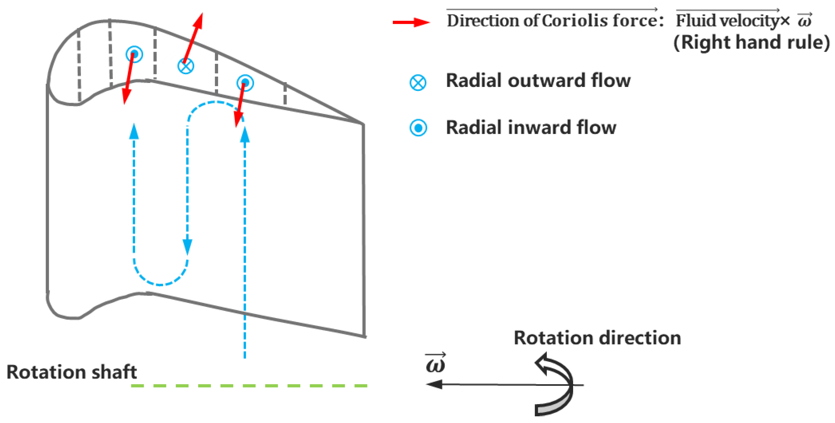
It can be concluded that a conventional rotating smooth channel has higher heat transfer on the pressure side of the radial outward flow pass and suction side of the radial inward flow pass but possesses lower heat transfer on the suction side of the radial outward flow pass and pressure side of the radial inward flow pass [60,61,62,63,64,65,66,67,68,69,70,71,72,73,74]. The reason why these heat transfer characteristics exist is because of the influence of the Coriolis force, which can be explained based on Figure 3. According to Figure 3, the side with the Coriolis force pointing at it has Coriolis-induced secondary flow flushing and thus possesses higher heat transfer performance, while the side with Coriolis force pointing opposite has lower heat transfer because of the secondary flow leaving. Therefore, the heat transfer difference between the pressure side and the leading side of a rotating passage is significant, leading to an obvious non-uniform heat transfer distribution.

2.2. Interaction Mechanisms of Coriolis Force and Turbulators on Flow Pattern

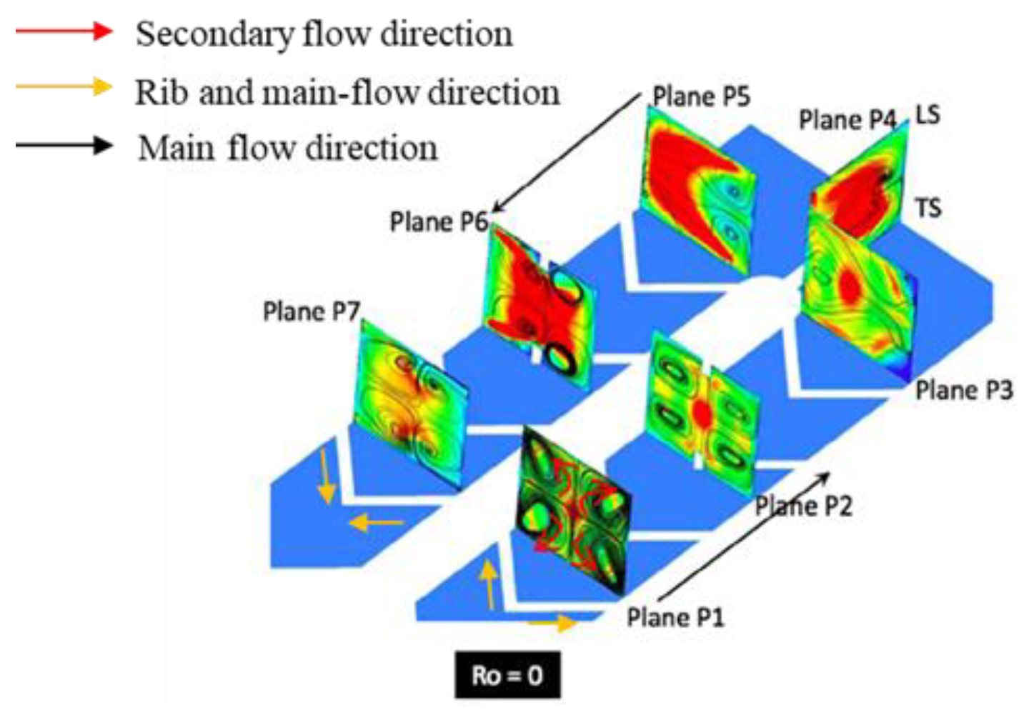
Turbulators, especially ribs, are always arranged on the leading and trailing walls of the internal serpentine channel to enhance heat transfer ability. Slanting straight ribs configured on both the leading and the trailing walls can induce secondary flow in a stationary passage, as shown in Figure 4 [75]. A pair of vortices exist in the pass as depicted with the two black circles with arrows. The circulation direction of the secondary flow depends on the rib and main flow orientations. Moreover, in a non-rotational channel, V-ribs that are arranged on both the leading and the trailing walls cause two pairs of vortices, as depicted in plane P1 and P2 of Figure 5 [76]. The circulation direction of the secondary flow depends on the V-rib and main flow orientations as well.
The common flow characteristic of a non-rotational ribbed channel is that the secondary flow near the ribbed wall always flows along the rib and main-flow direction and dominates the whole direction of the secondary flow.
When a channel is under rotating conditions, as illustrated in Figure 6 [76], the Coriolis-induced secondary flow near the trailing wall strengthens the secondary flow induced by the V-ribs on the trailing wall, thus enhancing the heat transfer, while weakening the secondary flow caused by the V-ribs on the leading wall, leading to a heat transfer deficit. With the flow going along the passage, the rib-induced secondary flow near the leading wall disappears, and the Coriolis-induced secondary flow merged with the rib-induced secondary flow dominates the channel flow structure. This is because the circulation direction of the rib-induced secondary flow near the trailing wall is the same as that of the Coriolis-induced secondary flow, but the rib-induced secondary flow near the leading wall is opposite.
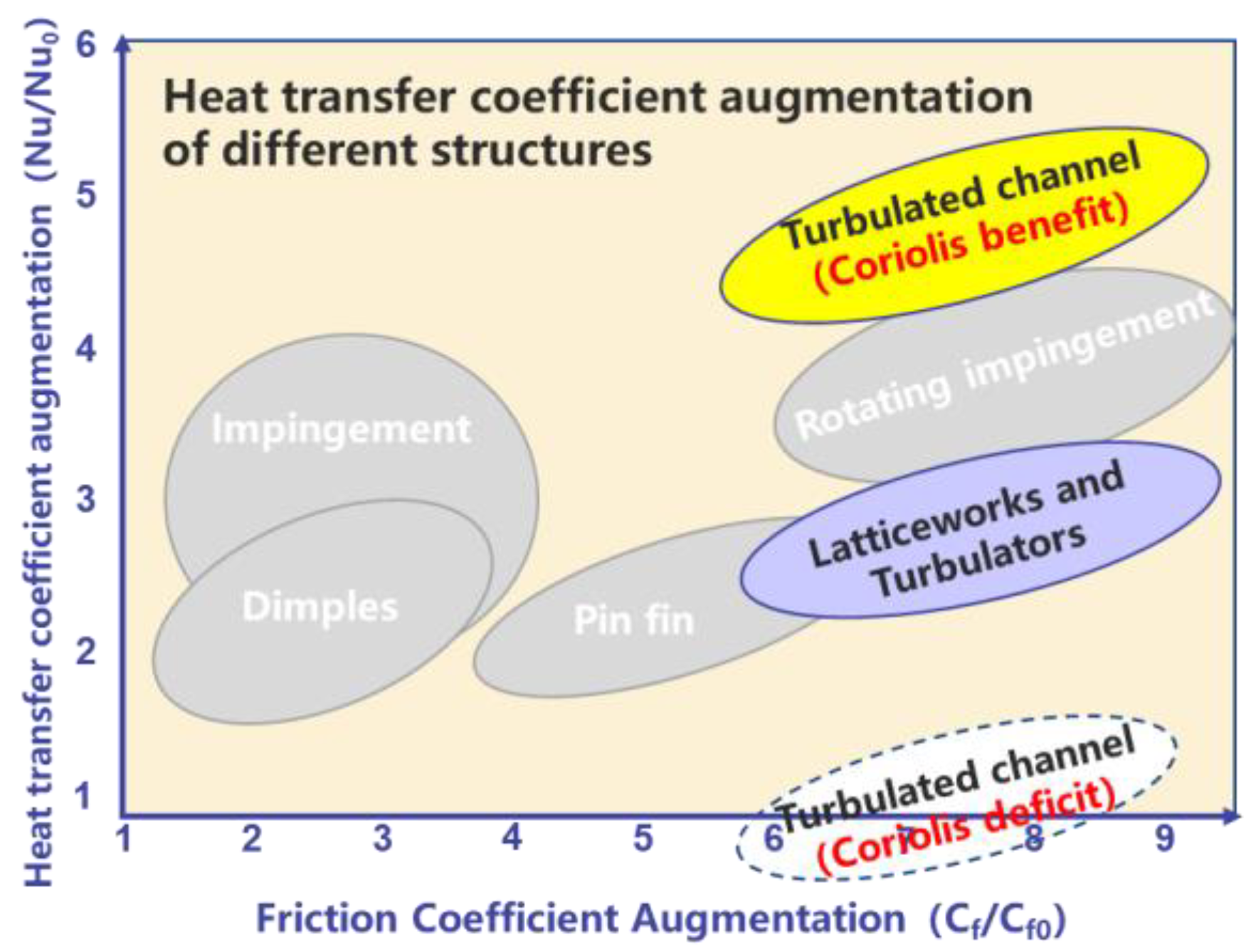
Therefore, when the circulation direction of the rib-induced secondary flow near the trailing or leading wall is the same as the Coriolis-induced secondary flow, the strength of the secondary flow can be enhanced and be good for heat transfer. Meanwhile, as the circulation direction of the rib-induced secondary flow near the trailing or leading wall is opposite to the Coriolis-induced secondary flow, the secondary flow can be weakened and can even disappear, which leads to a heat transfer deficit. Consequently, the Coriolis effect brings both benefits and deficits with regard to the heat transfer of conventional ribbed rotating channels, as illustrated in Figure 7 [77].
According to Section 2.1 and Section 2.2, under rotating conditions, the Coriolis force has both positive and negative influences on the heat transfer performance of conventional internal channels. However, how can we further enhance the heat transfer ability of rotating internal channels? Can we eliminate the negative heat transfer effect of the Coriolis force whilst also utilizing the positive heat transfer effect of the Coriolis force on the trailing and leading wall simultaneously?

3. Utilization of Coriolis Force

The answer to the question above is “Yes”. Many scholars [78,79,80] tried to weaken the Coriolis force’s negative effect on the rotating internal channel. They found that when a rotating channel has a channel orientation angle with a rotation shaft as depicted in Figure 1, the Coriolis-induced secondary flow was altered in the channel. And, the Coriolis force influence on the heat transfer was weakened compared to the rotating channel without a channel orientation angle, resulting in the heat transfer on the leading wall of the radial outward flow pass being augmented [81]. Moreover, lately, some researchers [77,82,83] attempted to utilize the Coriolis force positive heat transfer effect on leading and trailing walls simultaneously.

3.1. Weakening the Coriolis Force’s Negative Heat Transfer Effect

If the Coriolis force’s negative effect on heat transfer is weakened, the strength of the Coriolis force perpendicular to the trailing and leading walls will also decline. When a rotating channel has a channel orientation angle with a rotation shaft as depicted in Figure 1, based on the right-hand rule, the direction of the Coriolis force is not vertical to the trailing and leading walls. Hence, the Coriolis component force perpendicular to the leading and trailing wall can be reduced, leading to the Coriolis force’s negative effect on heat transfer being weakened. Tao et al. [59] investigated a wedge-shaped smooth channel with a rotating condition and found that the average Nu ratio of the suction to the pressure sides was prone to channel orientation. Al-Hadhrami et al. [83] analyzed the channel orientation angle effect on a rotating U-duct. They revealed that the orientation angle weakened the heat transfer difference between the suction and the pressure sides induced by the Coriolis force. Li Y. et al. [84,85,86] studied a U-channel under rotating conditions. Two orientation angles of 22.5° and 45° were comparatively studied. A similar conclusion was obtained that since the angle existed, the heat transfer difference between the suction and the pressure sides was lower than the channel without an orientation angle.
Hence, it can be concluded that when there is a channel orientation angle for a rotating channel, the Coriolis force effect on the suction and the pressure sides is weakened, leading to heat transfer differences between the suction sides and the pressure sides going down, meaning the Coriolis force’s negative effect on heat transfer is weakened. Furthermore, though the Coriolis force’s negative effect on heat transfer can be weakened, the Coriolis force’s positive effect on heat transfer is weakened as well due to the reduced Coriolis force strength imposed on the pressure and suction sides.

3.2. Utilizing the Coriolis Force’s Positive Heat Transfer Effect

3.2.1. Principle of Heat Transfer Augmentation and Study State

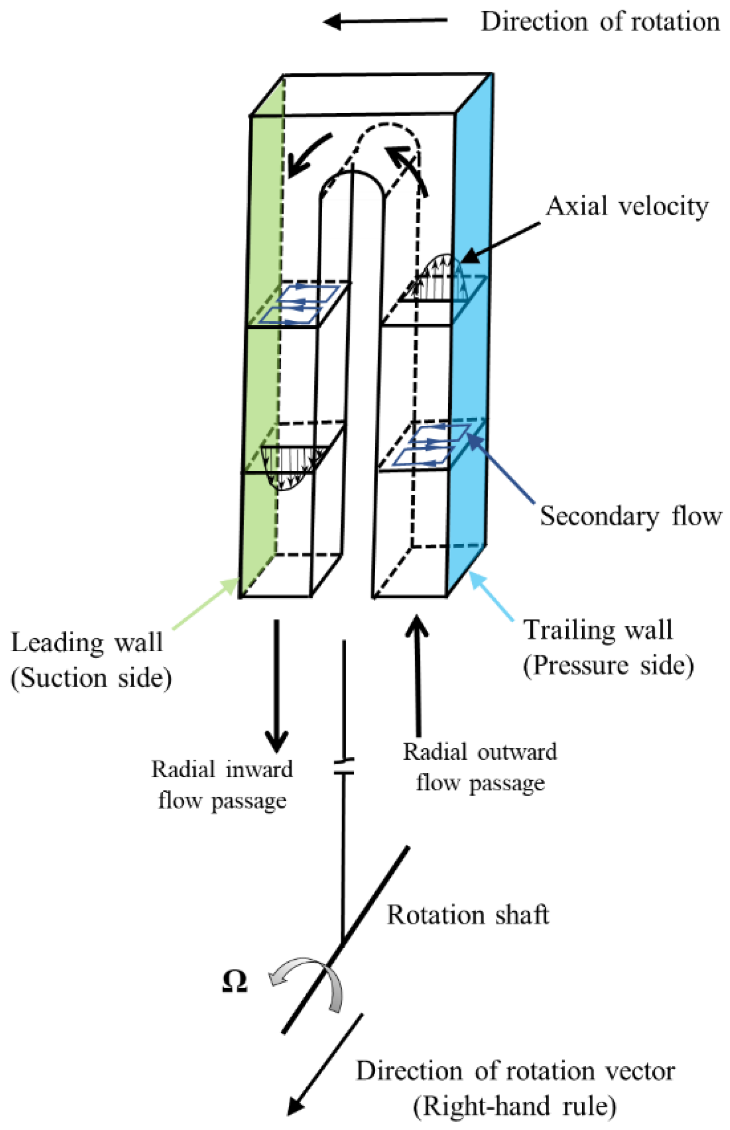
If the Coriolis force’s positive heat transfer effect can be utilized on the leading and the trailing walls simultaneously, the direction of the Coriolis force should point to the leading and the trailing walls at the same time. Considering the rotating vector direction and the cooling flow direction by using the right-hand rule, if the cooling air only initially flows along the pressure side, goes through a bend close to the blade tip, and then enters the pass flowing along the suction side (a channel orientation angle of 90°), then a Coriolis force pointing to the leading and trailing walls simultaneously can be achieved. The flow mechanisms of the channel with a channel orientation angle of 90° are illustrated in Figure 8. It should be noted that only if the main flow goes from the pass near the pressure side, and then enters the pass near the suction side, can the direction of the Coriolis force point to the leading and the trailing walls at the same time, bringing in heat transfer enhancement on both the pressure and the suction sides. However, if the flow direction is reversed, the direction of the Coriolis force would point to the partition wall, resulting in a heat transfer deficit on both the pressure and the suction sides simultaneously, which is not desirable.
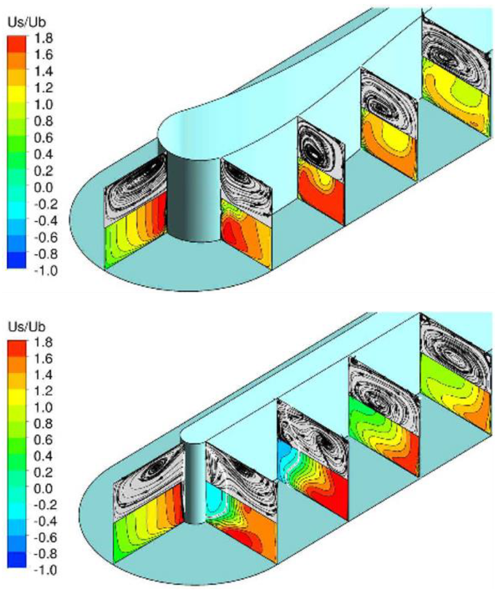
Dutta and Han [87] investigated a ribbed two-pass channel in a rotating state. The orientation angle was 90°. It turned out that the rotating channel with an orientation angle of 90° achieved better heat transfer augmentation than the conventional rotating channel without an orientation angle. Singh P. et al. [77] studied a rotating two-pass channel with ribs. Its orientation angle was 90° as well. The result showed that the Coriolis force played a positive role in the heat transfer of both the suction and the pressure sides. Tafti D. et al. [88] numerically studied a ribbed rotating channel with an orientation angle of 90°, as depicted in Figure 9 by LES, which revealed that compared to the stationary state, this novel rotating channel had a 10% increment of heat transfer and a 10% decrement of pressure loss. The lower pressure loss was probably because of centrifugal and buoyancy pumping. Ma Y. et al. [69] simulated a smooth rotating channel with an orientation angle of 90°. They demonstrated heat transfer increases on the leading and the trailing walls as Ro rose due to the utilization of the Coriolis force on both walls. Moreover, they optimized the bend region width between the bend wall and the tip wall and the thickness of the divider wall between the two passages. After optimization, heat transfer performances were 20.1% and 56.6% improved on the trailing wall and the leading wall, respectively. Moreover, Smirnov E. [4] also achieved the optimization of a smooth rotating channel with an orientation angle of 90°. The result illustrated that the pressure loss was significantly reduced, which is probably because of a more uniform velocity distribution at the exit of the bend area, as illustrated in Figure 10. After optimization, the pressure in the rotating channel was smaller than that of the non-rotational channel.
Therefore, from the above pieces of literature, the rotation is good for the heat transfer on both the leading and the trailing walls of the rotating channel with an orientation angle of 90°, due to the Coriolis force effect. Moreover, the structure benefits from pressure loss reduction [89]. Pressure loss is a vital parameter for the practical internal cooling structure design of the turbine blade because high pressure loss always leads to a high-temperature main flow going back into the blade, resulting in blade damage. Therefore, the rotating channel with an orientation angle of 90° has the advantage of less pressure loss, meaning that it is a promising structure for practical blade internal cooling design.

3.2.2. Heat Transfer Characteristics on Suction and Pressure Sides Compared with Conventional Rotating Channel

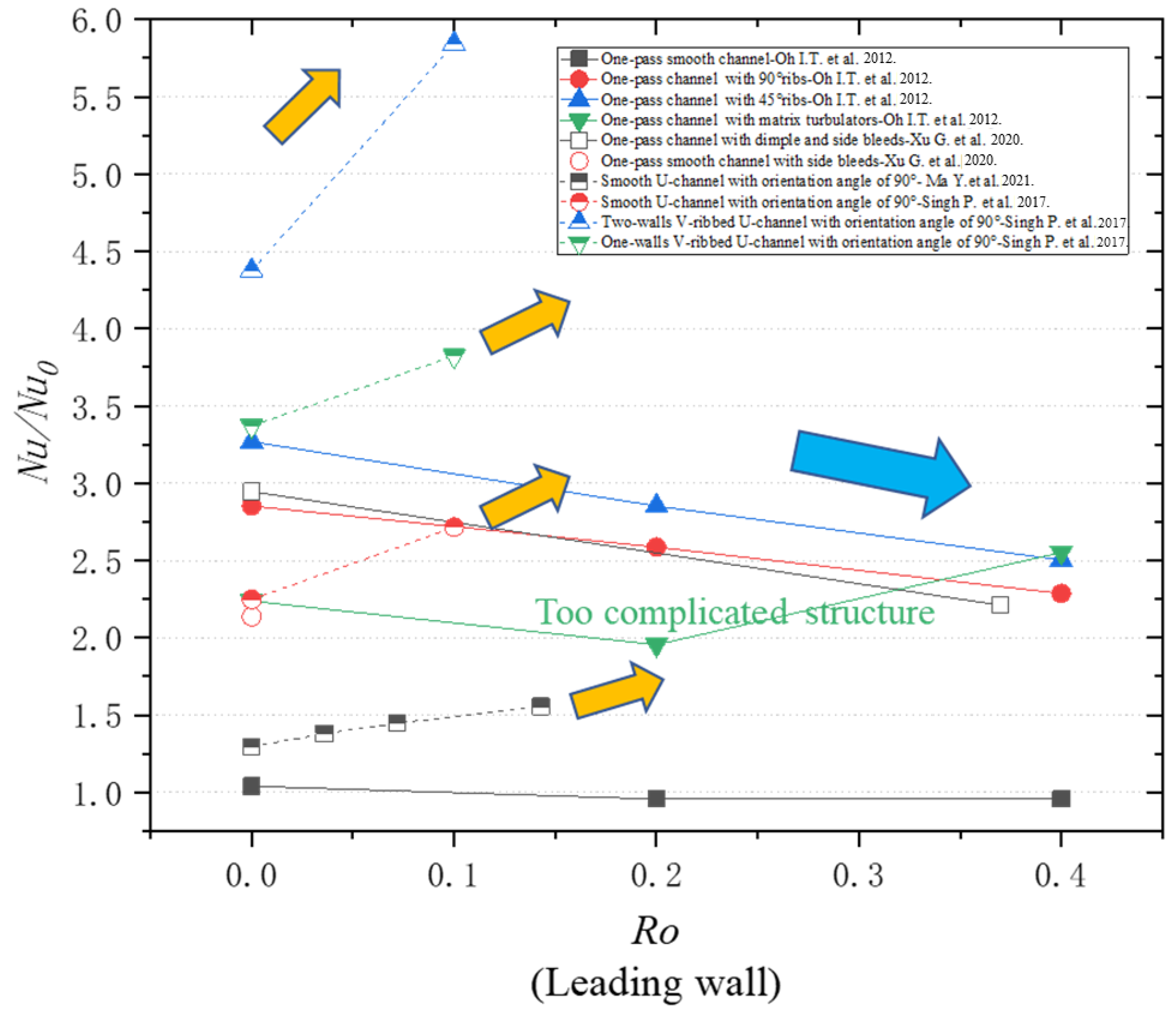
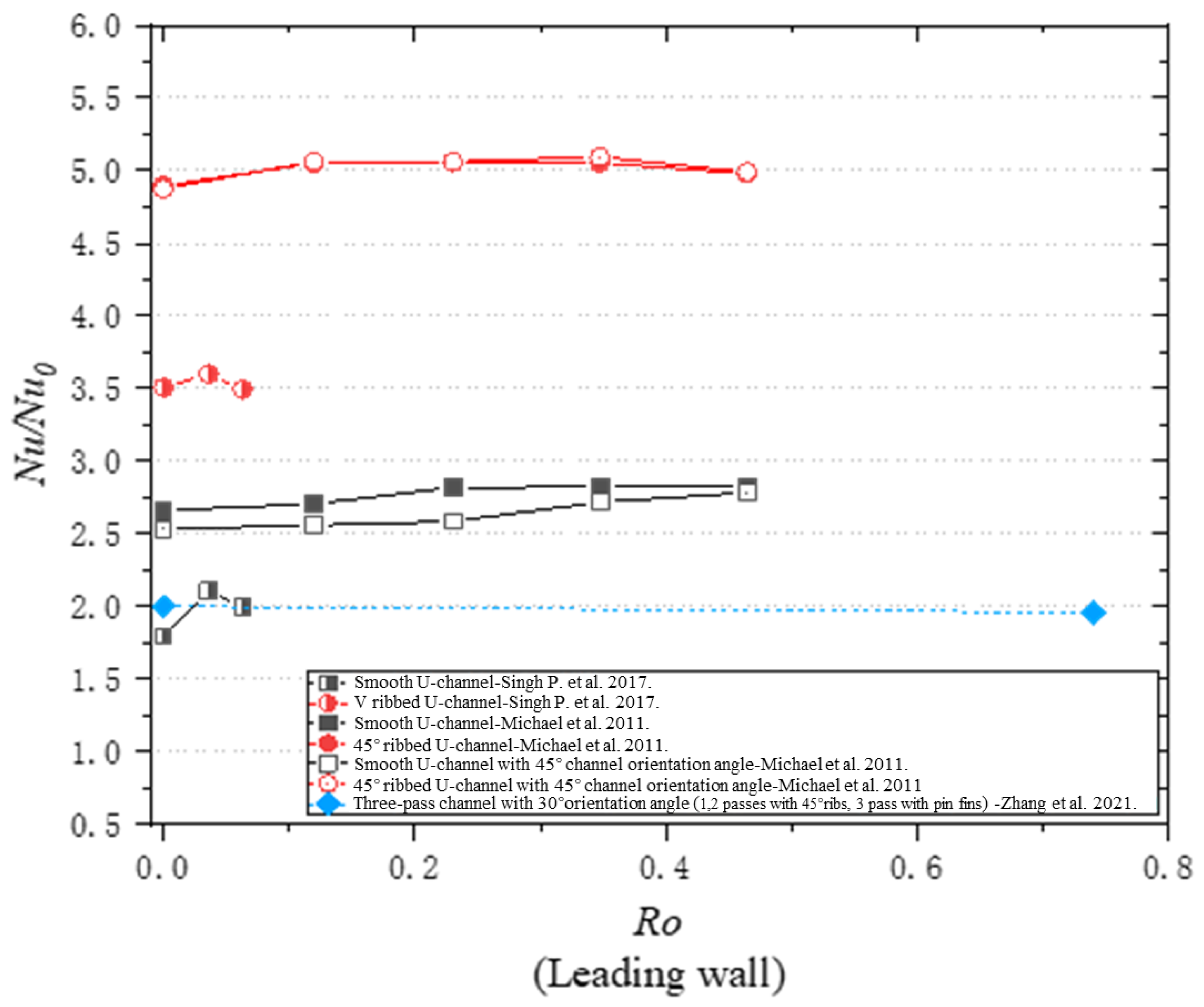
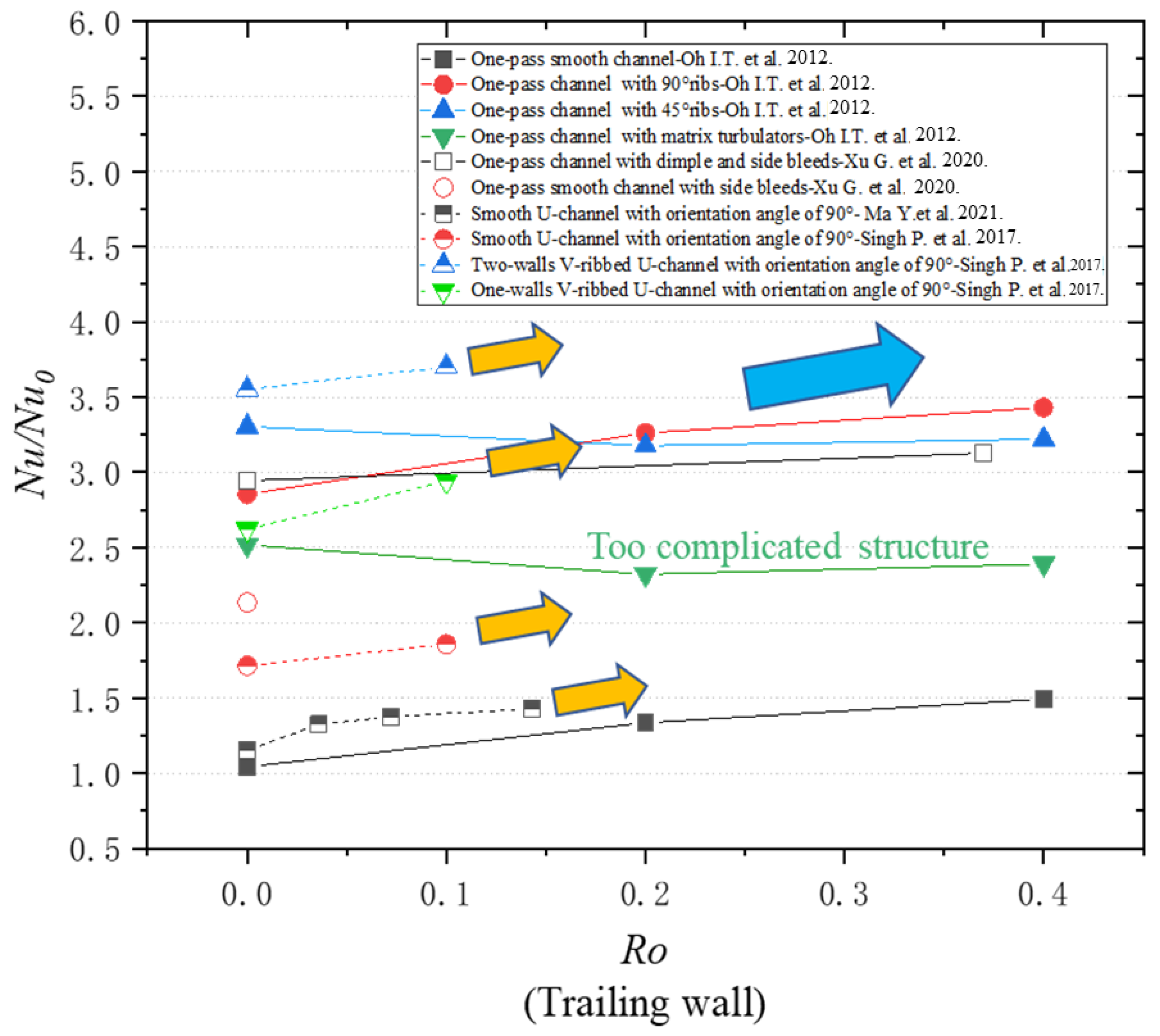
To more clearly compare the heat transfer abilities between a conventional rotating channel and a novel rotating channel with a channel orientation angle of 90°, the average Nu/Nu0 variations along the Ro on the leading and trailing walls are summarized in the paper, as depicted in Figure 11, Figure 12, Figure 13 and Figure 14.
According to Figure 11, the curves with the dashed line represent the average Nu/Nu0 variations of rotating channels with an orientation angle of 90° on the leading wall. And the rest of the curves represent one-pass conventional rectangular rotating channels without an orientation angle. The trends of the average Nu/Nu0 on the leading wall of one-pass conventional rectangular rotating channels mainly went down as the Ro increased from 0 to 0.4, except for the rotating channel with matrix turbulators due to its complicated turbulator structures. However, the trends of the average Nu/Nu0 on the leading wall of the rotating channels with an orientation angle of 90° are opposite, going up as Ro increases. The reasons for this are that the Coriolis force weakens the heat transfer on the leading wall of one-pass conventional rotating channels but augments the heat transfer on the leading wall of the rotating channels with an orientation angle of 90°.
In Figure 12, the average Nu/Nu0 variations along the Ro on the leading wall of two- or three-pass conventional channels with orientation angles of 0° and 45° are depicted. It can be observed that the rotation effect is not obvious because the Nu/Nu0 is averaged from the leading surfaces of two or three passages.
When Figure 11 and Figure 12 are comparatively analyzed, for the conventional rotating channel, rotation decreases the average heat transfer on the leading wall of one-pass conventional rectangular rotating channels, while having less effect on the average heat transfer averaged from the leading surfaces of two or three passages. Therefore, very non-uniform heat transfer induced by the Coriolis force exists on the leading walls of different passages with different flow directions when the Ro is smaller than 0.4. Similarly, the conclusion that very non-uniform heat transfer occurs on the trailing walls of different passages can be drawn as well, according to Figure 13 and Figure 14. However, since the Nu/Nu0 of the leading and the trailing walls in the novel rotating channel with a channel orientation angle of 90° rises with an increasing Ro, the Coriolis-induced non-uniform heat transfer effect can be avoided in the novel rotating channel. In Figure 11, the heat transfer of all the cooling rotating passages is increased as the Ro increases from 0 to 0.4 because of the Coriolis force-induced heat transfer augmentation, except for rotating passages with matrix turbulators due to their complicated cooling structure.
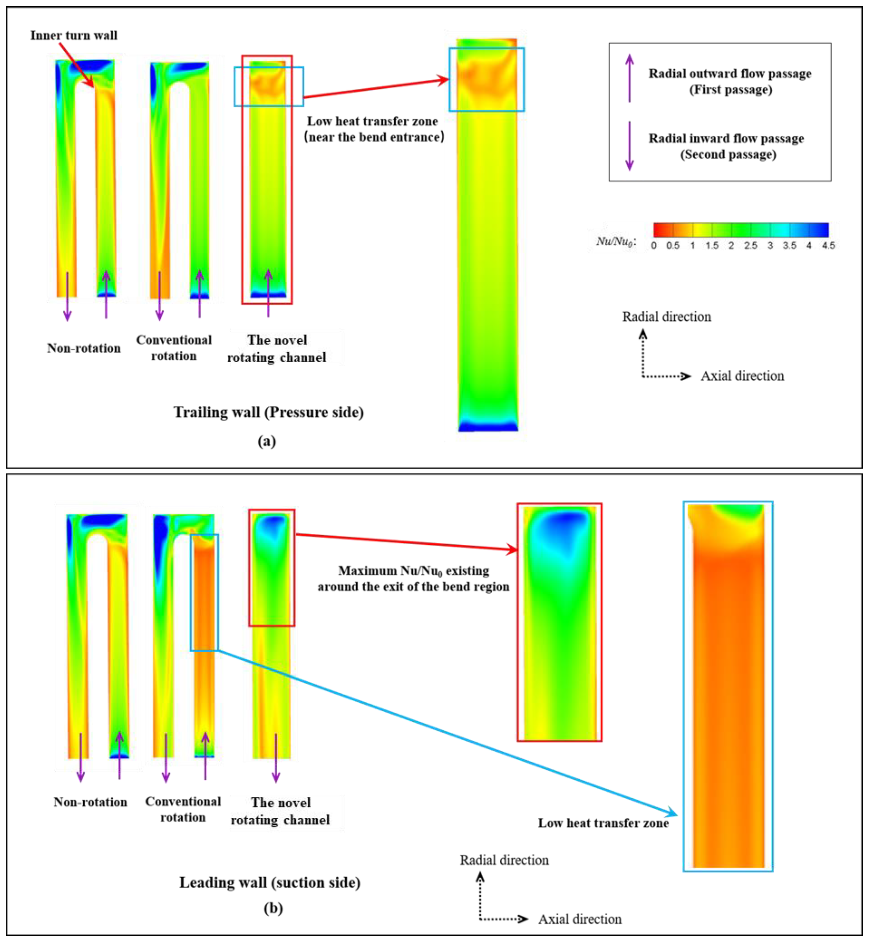
For a more focused comparison of the novel rotating channel with a channel orientation angle of 90° and a conventional one, the rotation effect on the heat transfer performance of the two channels is depicted in Figure 15 [82]. Based on the Nusselt number ratio contours, the low heat transfer region in the novel channel is smaller than in the conventional rotating channel, while the low heat transfer area of the conventional rotating channel due to the heat transfer deficit induced by the Coriolis force is larger. Therefore, the Coriolis force has a negative heat transfer influence on a conventional channel. Nevertheless, the novel rotating channel avoids the negative heat transfer induced by the Coriolis force.
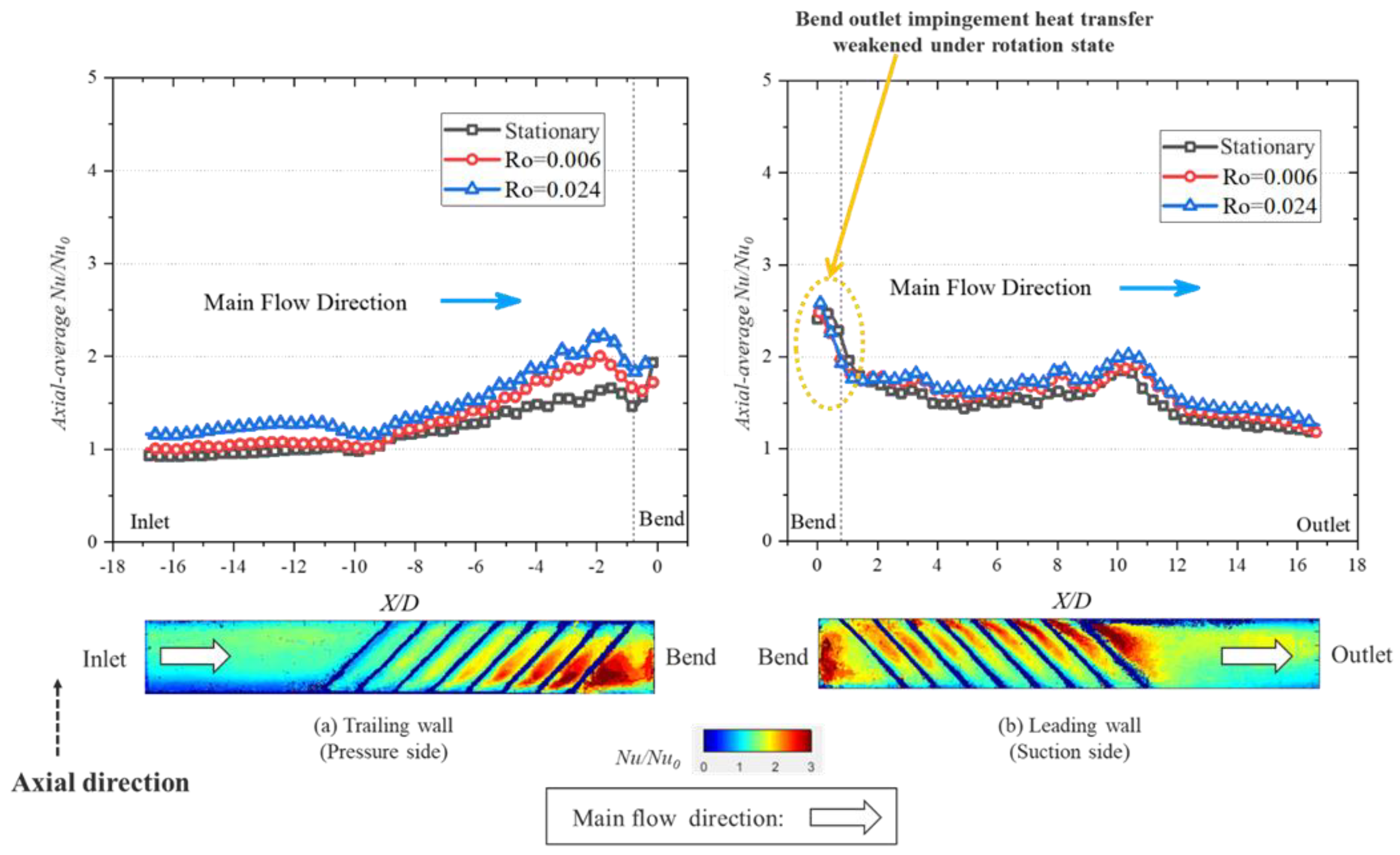
Figure 16 presents the rotation effect on the heat transfer ability of the novel rotating channel [94]. It can be clearly observed that rotation brings heat transfer enhancement on both the trailing and the leading walls, rather than a heat transfer deficit. Therefore, compared to the conventional rotating channel, the novel rotating channel does have the ability to utilize a positive rotation effect to augment the heat transfer on both the pressure and the suction sides.

4. Reynolds Number Effect on Bilaterally Enhanced U-Channel

Since a rotating channel with an orientation angle of 90° can utilize the Coriolis force heat transfer enhancement effect on both the pressure and the suction sides but has no unified name, a bilaterally enhanced U-channel is the name given to this novel rotating channel in this paper.
The non-dimensional equations for a bilaterally enhanced U-channel with incompressible and viscous flow are as follows [95].
u i x i = 0
u i t + u j u i x j + 2 R o · u 2 2 R o · u 1 0 = p x i + 1 R e 2 u i x j x j
Hence, based on Equations (1) and (2), Re and Ro are vital non-dimensional numbers that influence the performance of a bilaterally enhanced U-channel. Investigations into the effects of Ro and Re on bilaterally enhanced U-channels are essential.
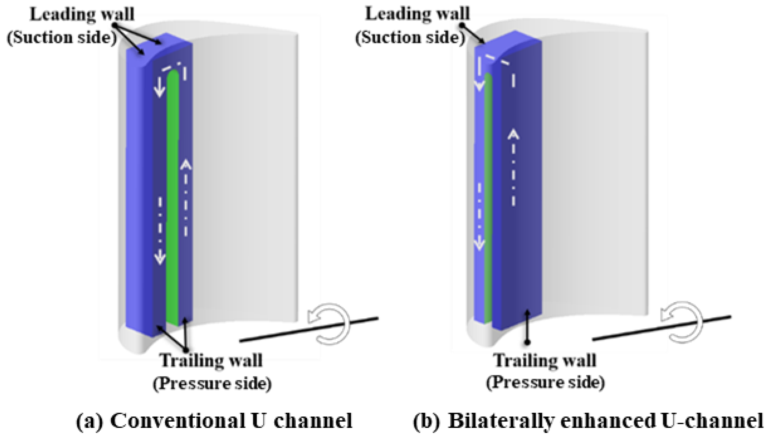
According to Section 3.2, the Ro effect on the heat transfer of the bilaterally enhanced U-channel was studied by some researchers [88,91]. A numerical study on a bilaterally enhanced U-channel was carried out by our research team as well [82]. The channel structures of a conventional and novel channel with a blade are depicted in Figure 17. The simulation results indicated that the overall heat transfer on both the leading and the trailing walls of the bilaterally enhanced U-channel was better than a conventional rotating smooth U-channel with a Ro of 0.025. The Coriolis force is good for a heat transfer boost on both the suction and the pressure sides, leading to an improved heat transfer ability as the Ro increases.
What is more, there is a significant gap in the bilaterally enhanced U-channel studies as there are fewer analyses on the Re influence on the heat transfer performance of a novel channel. Consequently, to further study the Re effect on a smooth bilaterally enhanced U-channel, simulations were carried out in this paper using a Re in the range of 20,000 to 40,000 with a constant Ro of 0.025 since this range is the most commonly used in many other pieces of literature [49,51].
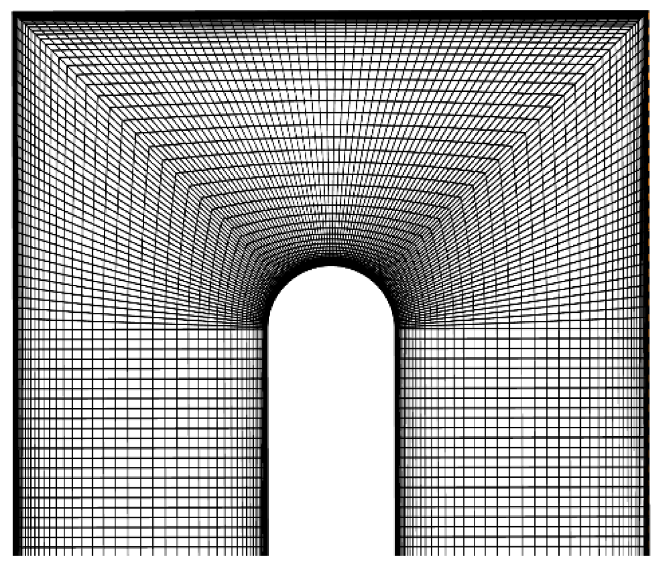
In the simulations, a structured mesh is utilized with a high mesh density near the walls to ensure a y+ of around 1, as depicted in Figure 18. The software of FLUENT and the approach of RANS are adopted. The SST k-ω model is chosen because of its good performance in predicting rotating channels [82]. For the boundary conditions, the Multi-Reference Frame method was used for rotating states. Relative to adjacent cell zone was selected in the reference frames of the inlet and outlet in the rotating channel. The inlet and outlet were set as velocity inlet and pressure outlet with zero gauges, respectively. The inlet velocity and the rotation speed are dependent on Ro and Re. Rotational no slip and heated wall boundary conditions with a constant heat flux of 2000 W/m2 were adopted for all the walls.
The simulation result compared with the experimental result [96] is demonstrated in Figure 19. According to the validation result, the simulation results meet the experimental result well.
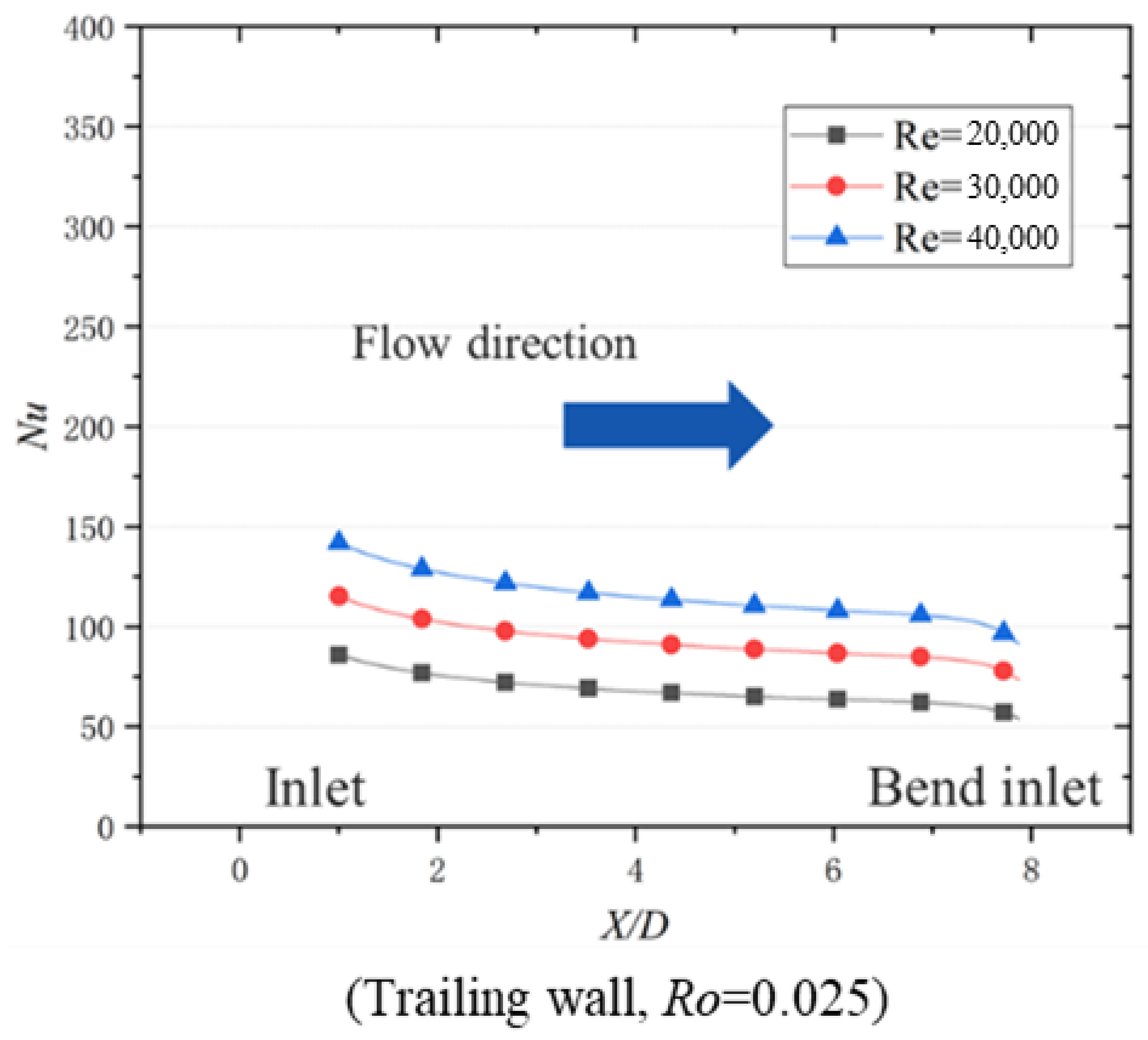
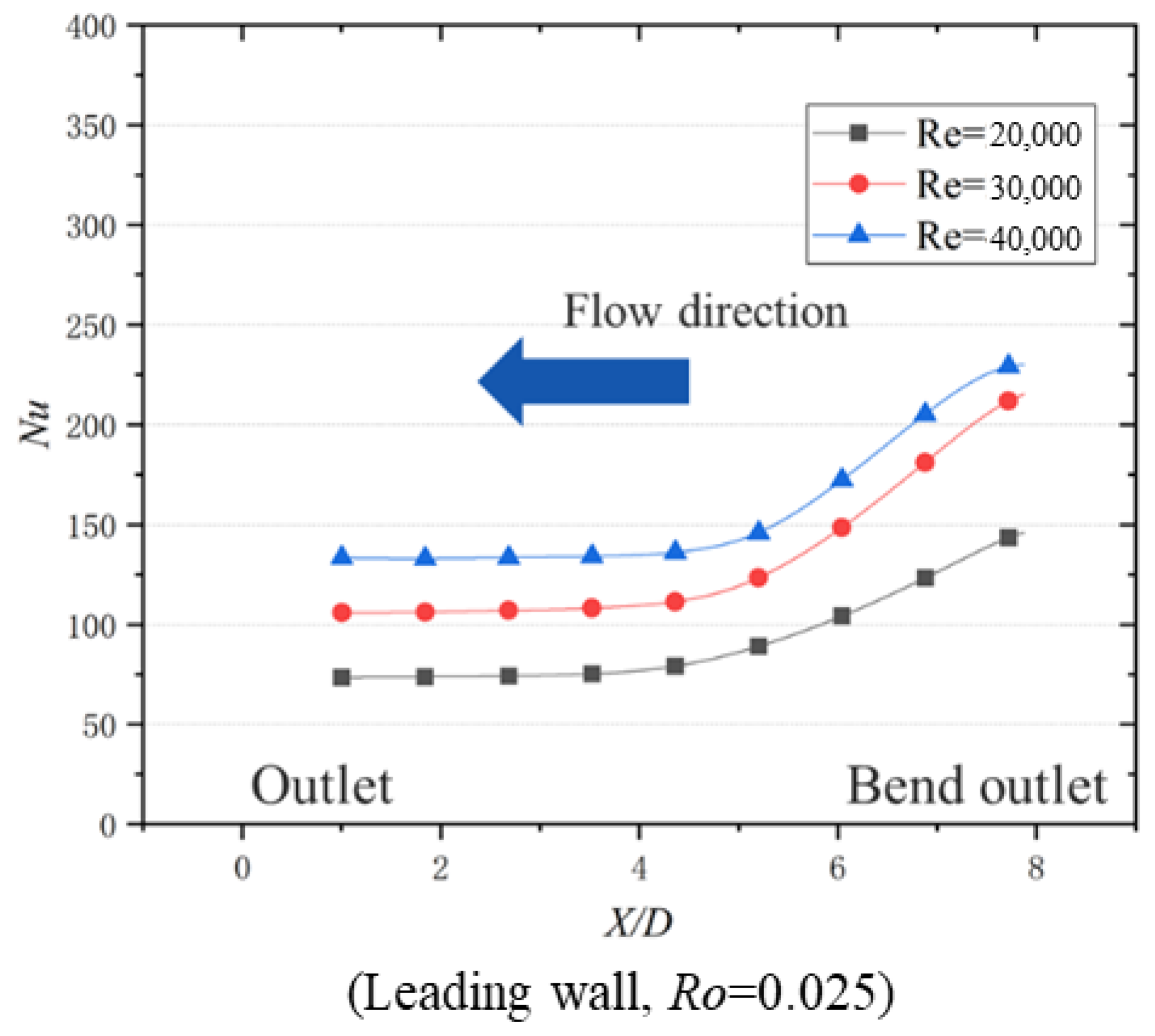
For the simulation studies, the results are demonstrated in Figure 20, Figure 21, Figure 22 and Figure 23. In Figure 20 and Figure 21, the average Nu represents that the wall Nusselt number is averaged along the axial direction, as depicted in Figure 16. The flow direction is the direction of the main coolant flow in the rotating channel. Based on Figure 20 and Figure 21, at the same Ro, all the Nu values have the same variation trend, going up as the Re increases. Thus, the Re benefits from the heat transfer ability on the leading and the trailing walls of the bilaterally enhanced U-channel. On the trailing wall presented in Figure 20, Nu is gradually reduced along the flow direction due to the development of a boundary layer in the radial outward flow pass. At Re = 20,000, Nu is in the range of 54 to 86. At Re = 30,000, Nu is in the range of 73 to 115. At Re = 40,000, Nu is in the range of 91 to 142. On the leading wall, illustrated in Figure 21, the maximum Nu occurs at the location of the bend outlet because of the flow impingement of the bend outlet on the leading wall of the radial inward flow pass. Along the flow direction of the radial inward flow pass, Nu is decreased since the flow impingement at the bend outlet is gradually weakened. When Re is 20,000, Nu ranges from 73 to 146. When Re is 30,000, Nu ranges from 106 to 215. When Re is 40,000, Nu ranges from 133 to 230.
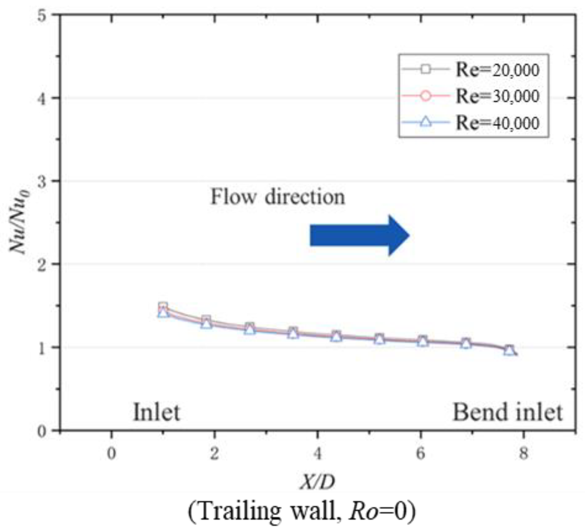
Figure 22 and Figure 23 depict the average Nu/Nu0 variations with different Re values along the flow direction on the trailing wall at Ro = 0 and 0.025. According to Figure 22 and Figure 23, at the same Ro condition, Re has less of an effect on Nu/Nu0. Therefore, when Ro is the same, Re plays a negligible role in heat transfer improvement (Nu/Nu0). Therefore, Ro and Re have an independent influence on the heat transfer performance of the bilaterally enhanced U-channel. When Re is in the range of 20,000 to 40,000 with non-rotational conditions, Nu/Nu0 is between 0.9 to 1.4. When Re is in the range of 20,000 to 40,000 with a Ro of 0.025, Nu/Nu0 is in the range of 1 to 1.5.
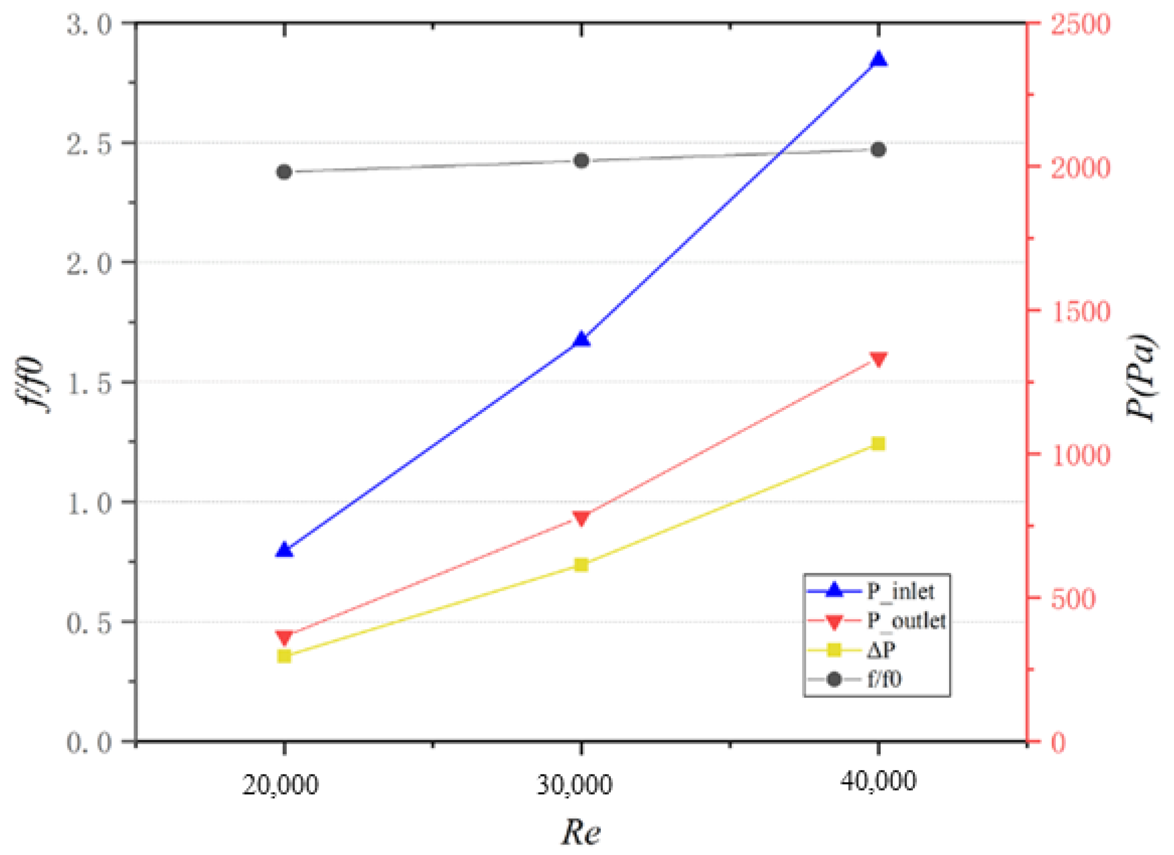
Figure 24 demonstrates the Re effect on the pressure loss of the bilaterally enhanced U-channel. At the same Ro, the pressures of the inlet and the outlet rise with increasing Re. The pressure difference between the inlet and the outlet grows from 365 to 1335 Pa as the Re ranges from 20,000 to 40,000. The friction factor ratio f/f0 has slightly increased from 2.37 to 2.46 with a Re from 20,000 to 40,000, which is probably because more viscous dissipation happens when the Re is higher.

5. Conclusions

In this paper, the influence of the Coriolis force, including the mechanisms, on conventional rotating channels is reviewed and analyzed. A way to utilize the positive heat transfer effect of the Coriolis force is proposed. Recent investigations on corresponding novel rotating channels called bilaterally enhanced U-channels are illustrated. Moreover, numerical investigations about the Re effects on bilaterally enhanced smooth U-channels were carried out in the study. The relevant conclusions can be drawn as follows:
  • For a conventional rotating channel, the trailing wall of the radial outward flow path and the leading wall of the radial inward flow path possess higher heat transfer performance, while the opposite walls perform lower heat transfer. This is because the leading or trailing wall with the Coriolis force pointing at it has Coriolis-induced secondary flow flushing and thus obtains heat transfer augmentation, but the opposite wall has the secondary flow leaving and thus leads to a heat transfer deficit.
  • Coriolis-induced secondary flow can interact with the rib-induced secondary flow, leading to heat transfer enchantment or weakened secondary flow. This is because when the circulation directions of the two-type secondary flows are the same, the secondary flow can be enhanced and thus improve heat transfer ability. However, as the circulation directions are opposite, the secondary flow is weakened by each other and can even disappear.
  • The channel orientation angle can weaken the strength of the Coriolis force applied on the trailing or leading wall. The reason for this is that there is a component Coriolis force applied on the wall when a channel orientation angle exists and the component Coriolis force is smaller, thus the strength of the Coriolis-induced secondary flow is smaller, leading to the Coriolis force effect being weakened.
  • A novel rotating U-channel with a channel orientation angle of 90° (called a bilaterally enhanced U-channel) can utilize the Coriolis force positive heat transfer effect on the leading and the trailing walls at the same time. This is because, according to the right-hand rule, when the main flow goes from the pass near the pressure side and then enters the pass near the suction side, the direction of the Coriolis force can simultaneously point to the leading and trailing walls, causing heat transfer enhancement on both the pressure and the suction sides.
  • Based on the non-dimensional equations for a bilaterally enhanced U-channel with incompressible and viscous flow, Re and Ro are vital non-dimensional numbers that influence the performance of a bilaterally enhanced U-channel. Combined with the research results, Ro is good for the heat transfer of bilaterally enhanced U-channels on both the leading and the trailing walls. At the same Ro, Re positively affects the Nu on the leading and the trailing walls of a Coriolis-utilization rotating smooth U-channel but plays a negligible role on Nu/Nu0.
In different stationary cooling channels, the Coriolis force exists in the internal rotating channel due to the rotation effect, resulting in heat transfer enhancement and deficit simultaneously on the trailing or leading walls in a conventional rotating U-channel. Therefore, the heat transfer ability of the conventional rotating channel is restricted owing to the Coriolis force. However, the bilaterally enhanced U-channel with a channel orientation angle of 90° is promising for solving the Coriolis force-induced heat transfer deficit and even augments heat transfer performance on both the trailing and the leading walls by utilizing the rotating effect. Moreover, it has the advantage of less pressure loss, meaning that the bilaterally enhanced U-channel is an encouraging and promising internal cooling structure for real-world turbine rotating blade design.

Author Contributions

Conceptualization, X.G. and X.L.; writing—original draft preparation, X.G., X.L. and J.R.; supervision, X.L. and J.R. All authors have read and agreed to the published version of the manuscript.

Funding

This research was funded by National Science and Technology Major Project (J2019-III-0007-0050).

Data Availability Statement

Data will be made available on request.

Acknowledgments

This work was financially supported by the National Science and Technology Major Project (J2019-III-0007-0050).

Conflicts of Interest

The authors declare no conflict of interest.

Nomenclature

Nulocal Nusselt number
N u = h D h λ
Nu0Nusselt number from the Dittus–Boelter correlation
N u 0 = 0.023 R e 0.8 P r 0.4
Nu/Nu0Nusselt number ratio
ffriction factor standing for pressure loss in a pipe
f = ( P o u t P i n ) D h 2 ρ u i n 2 L
f0friction factor obtained by fully-developed turbulent flow in a smooth duct
f 0 = 0.079 R e 0.25
f/f0friction factor ratio
ReReynolds number
R e = u i n D h ν
RoRotation number
R o = Ω D h u i n
BuoBuoyancy parameter
hheat transfer coefficient
Dhhydraulic diameter
λ thermal conductivity
P r Prandtl Number
P o u t outlet pressure
P i n inlet pressure
u i n inlet bulk velocity
ρ air density
L channel length from the inlet to outlet
ν fluid kinematic viscosity
Ω rotation speed
LESlarge eddy simulation
ARaspect ratio

References

  1. Acharya, S.; Kanani, Y. Chapter Three—Advances in Film Cooling Heat Transfer. Adv. Heat Transf. 2017, 49, 91–156. [Google Scholar]
  2. Han, J.C. Turbine Blade Cooling Studies at Texas A&M University: 1980–2004. J. Thermophys. Heat Transf. 2006, 20, 161–187. [Google Scholar]
  3. Fedorov, R.V.; Kovalnogov, V.N.; Zolotov, A.N. Development and study of technical solutions for turbine blades cooling. In Proceedings of the International Conference of Numerical Analysis and Applied Mathematics (ICNAAM), Thessaloniki, Greece, 25–30 September 2018; Available online: https://pubs.aip.org/aip/acp/article/1978/1/470024/772457/Development-and-study-of-technical-solutions-for (accessed on 14 July 2024).
  4. Smirnov, E.; Panov, D.; Ris, V. Goryachev V. Towards DES in CFD-based optimization: The case of a sharp U-bend with/without rotation. J. Mech. Sci. Technol. 2020, 34, 1557–1566. [Google Scholar] [CrossRef]
  5. Borello, D.; Salvagni, A.; Hanjali, K. Effects of rotation on flow in an asymmetric rib-roughened duct: LES study. Int. J. Heat Fluid Flow 2015, 55, 104–119. [Google Scholar] [CrossRef]
  6. Shevchenko, I.; Kindra, V.; Bychkov, N. A Numerical Study of Heat and Mass Transfer in a Narrowing Channel with Pin Fin-Dimple Arrays. In Proceedings of the International Multi-Conference on Industrial Engineering and Modern Technologies, Vladivostok, Russia, 3–4 October 2018; Available online: https://ieeexplore.ieee.org/document/8602582 (accessed on 2 July 2024).
  7. Kolesova, E.G.; Zhornik, M.N.; Kolesova, A.A. The experimental study of heat transfer in the channels of the vortex matrices of gas turbine blades. In Proceedings of the Heat and Mass Transfer and Hydrodynamics in Swirling Flows (HMTHSF-2019), Rybinsk, Russia, 16–18 October 2019; Available online: https://pubs.aip.org/aip/acp/article/2211/1/070005/995960/The-experimental-study-of-heat-transfer-in-the (accessed on 12 July 2024).
  8. Baybuzenko, I.N. Local Heat Transfer and Friction Measurements in Ribbed Channel at High Reynolds Numbers. In Proceedings of the ASME Turbo Expo 2021: Turbomachinery Technical Conference and Exposition, Online, 7–11 June 2021; Available online: https://asmedigitalcollection.asme.org/GT/proceedings/GT2021/84980/V05BT13A001/1120074 (accessed on 21 July 2024).
  9. Sokolov, N.P.; Polishchuk, V.G.; Andreev, K.D.; Rassokhin, V.A.; Zabelin, N.A. Heat transfer and pressure drop in rectangular channels with crossing fins (a Review). Therm. Eng. 2015, 62, 423–433. [Google Scholar] [CrossRef]
  10. Saxer-Felici, H.; Naik, S.; Gritsch, M.; Sedlov, A. Heat Transfer Enhancement for a Turbine Blade Leading Edge Passage Using Various Turbulator Geometries. In Proceedings of the ASME Turbo Expo 2014: Turbine Technical Conference and Exposition, Dusseldorf, Germany, 16–20 June 2014. [Google Scholar]
  11. Ris, V.V.; Galaev, S.A.; Levchenya, A.M.; Pisarevskii, I.B. Numerical Investigation of a Developed Turbulent Flow and Heat Transfer in a Rectangular Channel with Single-Sided Internal Ribs. Therm. Eng. 2021, 71, 167–175. [Google Scholar] [CrossRef]
  12. Naik, S.; Retzko, S.; Gritsch, M.; Sedlov, A. Impact of Turbulator Design on the Heat Transfer in a High Aspect Ratio Triangular Passage of a Turbine Blade. In Proceedings of the ASME Turbo Expo: Turbine Technical Conference and Exposition, Dusseldorf, Germany, 16–20 June 2014; Available online: https://www.semanticscholar.org/paper/Impact-of-Turbulator-Design-on-the-Heat-Transfer-in-Naik-Retzko/cda3a285c57fcd4a652d718067dbb892578d6322 (accessed on 26 June 2024).
  13. Han, J.; Dutta, S. Recent Developments in Turbine Blade Internal Cooling. Ann. N. Y. Acad. Sci. 2001, 934, 162–178. [Google Scholar] [CrossRef]
  14. Ligrani, P.; Blaskovich, T.; Oliveira, M. Comparison of Heat Transfer Augmentation Techniques. AIAA J. 2003, 41, 337–362. [Google Scholar] [CrossRef]
  15. Han, J. Recent Studies in Turbine Blade Cooling. Int. J. Rotating Mach. 2004, 10, 443–457. [Google Scholar]
  16. Wright, L.; Han, J. Heat Transfer Enhancement for Turbine Blade Internal Cooling. J. Enhanc. Heat Transf. 2014, 21, 111–140. [Google Scholar] [CrossRef]
  17. Ligrani, P. Heat Transfer Augmentation Technologies for Internal Cooling of Turbine Components of Gas Turbine Engines. Int. J. Rotating Mach. 2013, 2013, 275653. [Google Scholar] [CrossRef]
  18. Bunker, R. Evolution of Turbine Cooling. In Proceedings of the ASME Turbo Expo 2017: Turbomachinery Technical Conference and Exposition, Charlotte, NC, USA, 26–30 June 2017. [Google Scholar] [CrossRef]
  19. Ekkad, S.V.; Singh, P. Detailed Heat Transfer Measurements for Rotating Turbulent Flows in Gas Turbine Systems. Energies 2020, 14, 39. [Google Scholar] [CrossRef]
  20. Du, W.; Luo, L.; Jiao, Y.; Songtao, W. Heat transfer in the trailing region of gas turbines—A state-of-the-art review. Appl. Therm. Eng. 2021, 199, 117614. [Google Scholar] [CrossRef]
  21. Yeranee, K.; Yu, R. A review of recent studies on rotating internal cooling for gas turbine blades. Chin. J. Aeronaut. 2021, 34, 85–113. [Google Scholar] [CrossRef]
  22. Wagner, R.E.; Velkoff, H.R. Measurements of Secondary Flows in a Rotating Duct. J. Eng. Gas Turbines Power 1972, 94, 261–270. [Google Scholar] [CrossRef]
  23. Johnston, J.P.; Halleent, R.M.; Lezius, D.K. Effects of spanwise rotation on the structure of two-dimensional fully developed turbulent channel flow. J. Fluid Mech. 1972, 56, 533–557. [Google Scholar] [CrossRef]
  24. Moon, I.M. Effects of Coriolis Force on the Turbulent Boundary Layer in Rotating Fluid Machines. Undergraduate Thesis, Department of Mechanical Engineering, Massachusetts Institute of Technology, Cambridge, MA, USA, 1964. [Google Scholar]
  25. Ito, H.; Nanbu, I.C. Flow in Rotating Straight Pipes of Circular Cross Section, ASME Preprint 70-WA/FE-13, December 1970. Available online: https://asmedigitalcollection.asme.org/fluidsengineering/article/93/3/383/395774/Flow-in-Rotating-Straight-Pipes-of-Circular-Cross (accessed on 12 July 2024).
  26. Morris, W.D.; Ayhan, T. Observations on the influence of rotation on heat transfer in the coolant channels of gas turbine rotor blades. Proc. Inst. Mech. Eng. 1979, 193, 303–311. [Google Scholar] [CrossRef]
  27. Metzger, D.E.; Stan, R.L. Entry Region Heat Transfer in Rotating Radial Tubes. J. Energy 1977, 1, 297–300. [Google Scholar] [CrossRef]
  28. El-Masri, M.A.; Louis, J.F. On the Design of High-Temperature Gas Turbine Blade Water-Cooling Channels. J. Eng. Gas Turbines Power 1978, 100, 586–591. [Google Scholar] [CrossRef]
  29. Amosd, J. Fluid Cooled Turbine Rotor Blade Has Insert with Coolant Passageways and Also Has Bifurcated Roots. US3902820-A, 2 September 1975. [Google Scholar]
  30. Electric Power Research Institute. Advanced Cooled-Engine Shell/Spar Turbine Vanes and Blades. Available online: https://www.epri.com/research/products/AP-4751 (accessed on 2 July 2024).
  31. Slitenko, A.F. Gas-turbine rotor cooling systems. Power Eng.—J. Acad. Sci. USSR 1986, 24, 155–159. [Google Scholar]
  32. Mudawar, I.A. Boiling Heat Transfer in Rotating Channels with Reference to Gas Turbine Blade Cooling. Doctoral Dissertation, Massachusetts Institute of Technology, Cambridge, MA, USA, 1984. [Google Scholar]
  33. Shrestha, S.; Prasad, A.; Ricklick, M. Internal Cooling of Rotating and Non-Rotating Channels with Rib Turbulators. In Proceedings of the 2018 AIAA Aerospace Sciences Meeting, Kissimmee, FL, USA, 8–12 January 2018. [Google Scholar]
  34. Yonghui, X.; Qi, J.; Di, Z.; Zhongyang, S.; Wei, J. Review on Research of Heat Transfer Performance for Gas Turbine Blade Cooling Channel. Proc. Chin. Soc. Electr. Eng. 2017, 6, 1711–1720. [Google Scholar]
  35. Xu, T.; Shi, D.B.; Zhang, D. Flow and Heat Transfer Characteristics of the Turbine Blade Variable Cross-Section Internal Cooling Channel with Turning Vane. Appl. Sci. 2023, 13, 1446. [Google Scholar] [CrossRef]
  36. Amano, R.S.; Beyhaghi, S. Heat Transfer in a Rotating Two-pass Square Channel Representing Internal Cooling of Gas Turbine Blades. In Proceedings of the Aiaa Aerospace Sciences Meeting, Turbine Cooling, AIAA 2016-0655, San Diego, CA, USA, 4–8 January 2016. [Google Scholar]
  37. Lorenzon, A.; Casarsa, L. Validation of the Transient Liquid Crystal Thermography Technique for Heat Transfer Measurements on a Rotating Cooling Passage. Energies 2020, 13, 4759. [Google Scholar] [CrossRef]
  38. Saravani, M.S.; Amano, R.S. Heat Transfer Enhancement in Stationary and Rotating Internal Cooling Channels using Angled Ribs. In Proceedings of the 2019 AIAA Science and Technology Forum and Exposition, San Diego, CA, USA, 7–11 January 2019. [Google Scholar]
  39. Fang, Y. Effects of High Buoyancy Parameter on Flow and Heat Transfer of Two-Pass Smooth/Ribbed Channels. Energies 2021, 15, 148. [Google Scholar] [CrossRef]
  40. Liang, C.; Rao, Y.; Chen, J.; Luo, X. Experimental and Numerical Study of the Turbulent Flow and Heat Transfer in a Wedge-Shaped Channel with Guiding Pin Fin Arrays Under Rotating Conditions. J. Turbomach. 2022, 144, 071007. [Google Scholar] [CrossRef]
  41. Shi, D.; Xu, T.; Chen, Z.; Zhang, D.; Xie, Y. The effect of dimple/protrusion arrangements on the comprehensive thermal performance of variable cross-section rotating channels for gas turbine blades. Int. J. Therm. Sci. 2024, 196, 108733. [Google Scholar] [CrossRef]
  42. Chia, K.C.; Huang, S.C.; Liu, Y.H. Experimental Investigation of Heat Transfer on the Internal Tip Wall in a Rotating Two-Pass Rectangular Channel. J. Therm. Sci. Eng. Appl. 2021, 13, 011025. [Google Scholar] [CrossRef]
  43. Zhang, D.W.; Li, H.W.; Tian, Y.T. Effects of a high Reynolds number and rotation on the leading-edge heat transfer of a ribbed cooling channel with a cross-section consisting of a semicircle and a rectangle. Int. J. Heat Mass Transf. 2022, 188, 122646. [Google Scholar] [CrossRef]
  44. Zhu, F.; Jing, Q.; Xie, Y.; Zhang, D. Numerical investigation on flow and heat transfer characteristics of U-shaped channels with side-wall column ribs. Int. Commun. Heat Mass Transf. 2022, 137, 106221. [Google Scholar] [CrossRef]
  45. Chen, I.L.; Sahin, I.; Wright, L.M.; Han, J.-C.; Krewinkel, R. Heat transfer in a rotating, blade-shaped, two-pass cooling channel with a variable aspect ratio. J. Turbomach.-Trans. ASME 2022, 144, 021011. [Google Scholar] [CrossRef]
  46. Ren, M.; Li, X.; Ren, J.; Jiang, H. Numerical Study on Local Heat Transfer in a Rotating Cooling Channel. In Proceedings of the ASME Turbo Expo 2018: Turbomachinery Technical Conference and Exposition, Oslo, Norway, 11–15 June 2018. [Google Scholar]
  47. Pattanaprates, N.; Juntasaro, E.; Juntasaro, V. Numerical Investigation on the Modified Bend Geometry of a Rotating Multipass Internal Cooling Passage in a Gas Turbine Blade. J. Therm. Sci. Eng. Appl. 2018, 10, 061003. [Google Scholar] [CrossRef]
  48. Chang, S.W.; Chen, C.A.; Lu, Y.E. Experimental study of heat-transfer and pressure-drop performances of a rotating two-pass channel with composite stepped skew ribs and internal effusion. Int. J. Heat Mass Transf. 2023, 212, 124308. [Google Scholar] [CrossRef]
  49. Wang, Z.; Yin, Y.; Yang, L.; Yan, L.; Luan, Y. Flow and Heat Transfer Performance of Channels with 45 Degree Ribs in Staggered Array. J. Appl. Fluid Mech. 2021, 14, 1535–1546. [Google Scholar]
  50. Ahn, J. Large Eddy Simulation of Flow and Heat Transfer in a Ribbed Channel for the Internal Cooling Passage of a Gas Turbine Blade: A Review. Energies 2023, 16, 3656. [Google Scholar] [CrossRef]
  51. Shi, D.; Jing, Q.; Gao, T.; Zhang, D.; Xie, Y. Flow and heat transfer mechanism of U-shaped channel considering variable cross-section and rotating effects. Int. Commun. Heat Mass Transf. 2021, 129, 105701. [Google Scholar] [CrossRef]
  52. Pouyaei, P.; Kayhani, M.H.; Norouzi, M.; Bahambari, A.B.; Kim, M.; Kim, K.C. Effect of a curved turning vane on the heat transfer and fluid flow of four-pass internal cooling channels of gas turbine blades. Proc. Inst. Mech. Eng. Part G-J. Aerosp. Eng. 2023, 237, 3726–3742. [Google Scholar] [CrossRef]
  53. Yang, S.F.; Wu, H.W.; Han, J.C.; Zhang, L.; Moon, H.-K. Heat transfer in a smooth rotating multi-passage channel with hub turning vane and trailing-edge slot ejection. Int. J. Heat Mass Transf. 2017, 109, 1–15. [Google Scholar] [CrossRef]
  54. Son, S.Y.; Kihm, K.D.; Han, J.C. PIV flow measurements for heat transfer characterization in two-pass square channels with smooth and 90° ribbed wall. Int. J. Heat Mass Transf. 2002, 45, 4809–4822. [Google Scholar] [CrossRef]
  55. Hosseinalipour, S.M.; Shahbazian, H.R.; Sunden, B. Experimental investigations and correlation development of convective heat transfer in a rotating smooth channel. Exp. Therm. Fluid Sci. 2018, 94, 316–328. [Google Scholar] [CrossRef]
  56. Qiu, L.; Deng, H.; Sun, J.; Tao, Z.; Tian, S. Pressure drop and heat transfer in rotating smooth square U-duct under high rotation numbers. Int. J. Heat Mass Transf. 2013, 66, 543–552. [Google Scholar] [CrossRef]
  57. Deng, H.; Qiu, L.; Tao, Z.; Tain, S. Heat transfer study in rotating smooth square U-duct at high rotation numbers. Int. J. Heat Mass Transf. 2013, 66, 733–744. [Google Scholar] [CrossRef]
  58. Li, H.; You, R.; Deng, H.; Tao, Z.; Zhu, J. Heat transfer investigation in a rotating U-turn smooth channel with irregular cross-section. Int. J. Heat Mass Transf. 2016, 96, 267–277. [Google Scholar] [CrossRef]
  59. Tao, Z.; Qiu, L.; Deng, H. Heat transfer in a rotating smooth wedge-shaped channel with lateral fluid extraction. Appl. Therm. Eng. 2015, 87, 47–55. [Google Scholar] [CrossRef]
  60. Hoseinalipour, S.M.; Shahbazian, H.; Sunden, B.A. Influences of secondary flow induced by Coriolis forces and angled ribs on heat transfer in a rotating channel. Int. J. Numer. Methods Heat Fluid Flow 2019, 29, 388–417. [Google Scholar] [CrossRef]
  61. Duchaine, F.; Gicquel LY, M.; Grosnickel, T.; Koupper, C. Large-Eddy Simulation of the Flow Developing in Static and Rotating Ribbed Channels. J. Turbomach. 2020, 142, 041003. [Google Scholar] [CrossRef]
  62. Hosseinalipour, S.M.; Shahbazian, H.; Sunden, B. Coriolis and buoyancy effects on heat transfer in viewpoint of field synergy principle and secondary flow intensity for maximization of internal cooling. Heat Mass Transf. 2021, 57, 1467–1483. [Google Scholar] [CrossRef]
  63. Zhang, X.; Li, H.; Tian, Y.; You, R.; Zhang, D.; Wu, A. Heat transfer in a rotating lateral outflow trapezoidal channel with pin fins under high rotation numbers and Reynolds numbers. Appl. Therm. Eng. 2022, 213, 118725. [Google Scholar] [CrossRef]
  64. Chen, I.L.; Sahin, I.; Wright, L.M.; Han, J.-C.; Krewinkel, R. Heat Transfer in a Rotating, Two-Pass, Variable Aspect Ratio Cooling Channel with Profiled V-Shaped Ribs. J. Turbomach. 2021, 143, 081013. [Google Scholar] [CrossRef]
  65. Ahn, J.; Choi, H.; Lee, J.S. Large eddy simulation of flow and heat transfer in a rotating ribbed channel. Int. J. Heat Mass Transf. 2007, 50, 4937–4947. [Google Scholar] [CrossRef]
  66. Saravani, M.S.; Dipasquale, N.J.; Beyhaghi, S.; Amano, R.S. Heat Transfer in Internal Cooling Channels of Gas Turbine Blades: Buoyancy and Density Ratio Effects. J. Energy Resour. Technol. 2019, 141, 112001. [Google Scholar] [CrossRef]
  67. Beyhaghi, S.; Saravani, M.S.; Morrison, M. Computational and Experimental Investigation of Heat Transfer in Stationary and Rotating Internal Cooling Ducts with High Rotation Numbers. In Proceedings of the 15th International Energy Conversion Engineering Conference, Atlanta, GA, USA, 11 July 2017. [Google Scholar]
  68. Deng, H.; Tao, Z.; Xu, G. Prediction of turbulent flow and heat transfer within rotating smooth U-shaped passage. J. Beijing Univ. Aeronaut. Astronaut. 2003, 29, 205–209. [Google Scholar]
  69. Ma, Y.; Cheng, Y.P.; Xie, J.; Zhou, Z.; Xu, J. Numerical investigation of internal cooling enhancement with Coriolis force in rotating gas turbine blades. J. Enhanc. Heat Transf. 2021, 28, 19–38. [Google Scholar] [CrossRef]
  70. Chang, S.W.; Cai, W.L.; Shen, H.D.; Yu, K.C. Uncoupling Coriolis Force and Rotating Buoyancy Effects on Full-Field Heat Transfer Properties of a Rotating Channel. J. Vis. Exp. 2018, 140, e57630. [Google Scholar]
  71. Chang, S.W.; Huang, S.W. Aerothermal performance of a rotating two-pass furrowed channel roughened by angled ribs. Appl. Therm. Eng. 2021, 199, 117613. [Google Scholar] [CrossRef]
  72. Sahin, I.; Chen, I.L.; Wright, L.M.; Han, L.C.; Xu, H.; Fox, M. Heat Transfer in Rotating, Trailing-Edge, Converging Channels With Smooth Walls and Pin-Fins. J. Turbomach. 2021, 143, 1–36. [Google Scholar] [CrossRef]
  73. Flynt, G.A.; Webster, R.S.; Sreenivas, K. Computation of heat transfer in turbine rotor blade cooling channels with angled rib turbulators. In Proceedings of the 49th AIAA/ASME/SAE/ASEE Joint Propulsion Conference, San Jose, CA, USA, 14–17 July 2013. [Google Scholar]
  74. Chang, S.W.; Liou, T.M.; Po, Y. Coriolis and rotating buoyancy effect on detailed heat transfer distributions in a two-pass square channel roughened by 45° ribs at high rotation numbers. Int. J. Heat Mass Transf. 2010, 53, 1349–1363. [Google Scholar] [CrossRef]
  75. Chen, W. Experimental and Numerical Study of the Mechanism of Internal Cooling in Gas Turbine Blade. Ph.D. Thesis, Tsinghua University, Beijing, China, 2011. Available online: https://kns.cnki.net/kcms/detail/detail.aspx?dbcode=CDFD&dbname=CDFD1214&filename=1013023958.nh&uniplatform=NZKPT&v=lut-saoAeW4s5BdP4VxUFM5_7vE3g7qZjkevxfSo9DLgD7kMVdDK35bPPmDtXpfw (accessed on 1 July 2024).
  76. Singh, P.; Li, W.; Ekkad, S.V.; Ren, J. A new cooling design for rib roughened two-pass channel having positive effects of rotation on heat transfer enhancement on both pressure and suction side internal walls of a gas turbine blade. Int. J. Heat Mass Transf. 2017, 115, 6–20. [Google Scholar] [CrossRef]
  77. Bunker, R.S.; Dees, J.E.; Palafox, P. Impingement Cooling in Gas Turbines: Design, Applications, and Limitations. Impingement Jet Cool. Gas Turbines 2014, 25, 1. [Google Scholar]
  78. Al-Qahtani, M.; Jang, Y.J.; Chen, H.C.; Han, J.C. Flow and heat transfer in rotating two-pass rectangular channels (AR=2) by Reynolds stress turbulence model. Int. J. Heat Mass Transf. 2002, 45, 1823–1838. [Google Scholar] [CrossRef]
  79. Liou, T.M.; Chang, S.W.; Hung, J.H.; Chiou, S.F. High rotation number heat transfer of a 45° rib-roughened rectangular duct with two channel orientations. Int. J. Heat Mass Transf. 2007, 50, 4063–4078. [Google Scholar] [CrossRef]
  80. Kim, S.; Choi, E.Y.; Kwak, J.S. Effect of Channel Orientation on the Distribution of the Heat Transfer Coefficient in Smooth and Dimpled Rotating Rectangular Channels. In Proceedings of the ASME 2010 International Mechanical Engineering Congress and Exposition. Volume 7: Fluid Flow, Heat Transfer and Thermal Systems, Parts A and B, Vancouver, BC, Canada, 12–18 November 2012; pp. 1611–1621. Available online: https://gasturbinespower.asmedigitalcollection.asme.org/IMECE/proceedings/IMECE2010/44441/1611/339650 (accessed on 25 July 2024).
  81. Parsons, J.A.; Han, J.C.; Zhang, Y. Effect of model orientation and wall heating condition on local heat transfer in a rotating two-pass square channel with rib turbulators. Int. J. Heat Mass Transf. 1995, 38, 1151–1159. [Google Scholar] [CrossRef]
  82. Guo, X.; Xu, H.; Li, X.; Ren, J. Flow and heat transfer characteristics of Coriolis-utilization rotating rectangular smooth cooling U-channel. Appl. Therm. Eng. 2022, 211, 118420. [Google Scholar]
  83. Han, A. Effect of rotation on heat transfer in two-pass square channels with five different orientations of 45° angled rib turbulators. Int. J. Heat Mass Transf. 2003, 46, 653–669. [Google Scholar]
  84. Li, Y.; Chen, J.; Liu, T.; Deng, H.; Xue, S. Heat transfer characteristics in a rotating AR=4:1 channel with different channel orientations at high rotation numbers. Propuls. Power Res. 2021, 10, 130–142. [Google Scholar] [CrossRef]
  85. Li, Y.; Deng, H.; Xu, G.; Qiu, L.; Tian, S. Effect of Channel Orientation on Heat Transfer in Rotating Smooth Square U-Duct at High Rotation Number. In Proceedings of the ASME Turbo Expo: Turbine Technical Conference & Exposition, Düsseldorf, Germany, 16–20 June 2014. [Google Scholar]
  86. Li, Y.; Deng, H.; Xu, G.; Tian, S. Heat transfer investigation in rotating smooth square U-duct with different wall temperature ratios and channel orientations. Int. J. Heat Mass Transf. 2015, 89, 10–23. [Google Scholar] [CrossRef]
  87. Dutta, S.; Han, J.C. Local Heat Transfer in Rotating Smooth and Ribbed Two-Pass Square Channels With Three Channel Orientations. J. Heat Transf. 1996, 118, 578–584. [Google Scholar] [CrossRef]
  88. Tafti, D.; Dowd, C.; Tan, X. High Reynold Number LES of a Rotating Two-Pass Ribbed Duct. Aerospace 2018, 5, 124. [Google Scholar] [CrossRef]
  89. Guo, X.X.; Wang, S.Y.; Li, X.Y.; Ren, J. Aerothermodynamic features of Coriolis-applied U channel. Int. J. Therm. Sci. 2024, 197, 108815. [Google Scholar] [CrossRef]
  90. Oh, I.T.; Kim, K.M.; Dong, H.L.; Park, J.S.; Cho, H.H. Local Heat/Mass Transfer and Friction Loss Measurement in a Rotating Matrix Cooling Channel. J. Heat Transf. 2012, 134, 011901.1–011901.9. [Google Scholar]
  91. Xu, G.; Chen, Y.; Wen, J. Heat transfer in a rotating rectangular channel (AR = 4) with dimples and sidewall bleeds. Int. J. Heat Mass Transf. 2020, 150, 119118.1–119118.14. [Google Scholar] [CrossRef]
  92. Huh, M.; Lei, J.; Han, J.C. Influence of Channel Orientation on Heat Transfer in a Two-Pass Smooth and Ribbed Rectangular Channel (AR = 2:1) Under Large Rotation Numbers. J. Turbomach. 2012, 134, 011022. [Google Scholar] [CrossRef]
  93. Zhang, B.L.; Zhu, H.R.; Liu, C.L.; Yao, C.Y. Experimental Study of Outflow Effects in a Rotating Turbulated Channel. J. Turbomach. 2021, 143, 071009. [Google Scholar] [CrossRef]
  94. Guo, X.X.; Li, X.Y.; Ren, J. Heat transfer and flow features of a Bifacial-enhanced U channel. Appl. Therm. Eng. 2024, 245, 122812. [Google Scholar] [CrossRef]
  95. Lezius, D.K.; Johnston, J.P. Roll-Cell Instabilities in Rotating Laminar and Turbulent Channel Flows. J. Fluid Mech. 1976, 77, 153–174. [Google Scholar] [CrossRef]
  96. Singh, P.; Ekkad, S. Experimental investigation of rotating rib roughened two-pass square duct with two different channel orientations. In Proceedings of the ASME Turbo Expo 2017: Turbomachinery Technical Conference and Exposition, GT2017-64225, Charlotte, NC, USA, 26–30 June 2017. [Google Scholar]
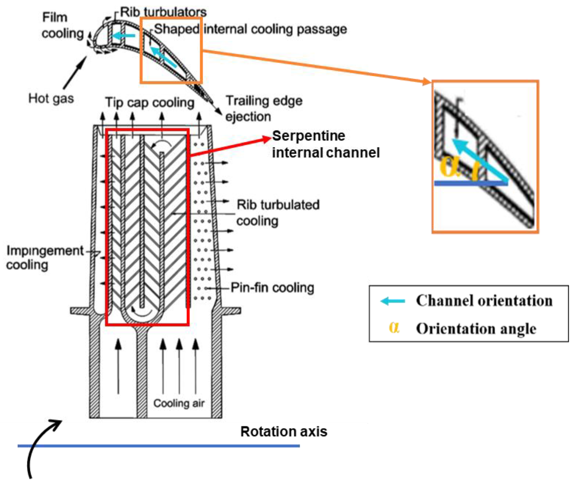
Figure 1. Schematic of internal channel in rotor blade [2].
Aerospace 11 00836 g001
Figure 2. Concept of inner channel structure of a rotor blade [33].
Aerospace 11 00836 g002
Figure 3. Direction of Coriolis force in a conventional rotating internal channel of a turbine blade.
Aerospace 11 00836 g003
Figure 4. Straight rib-induced secondary flow in a stationary passage [75].
Aerospace 11 00836 g004
Figure 5. V-rib-induced secondary flow in a stationary channel [76].
Aerospace 11 00836 g005
Figure 6. V-rib-induced secondary flow in a rotating channel [76].
Aerospace 11 00836 g006
Figure 7. Coriolis force effect on heat transfer of conventional, ribbed rotating channel [77].
Aerospace 11 00836 g007
Figure 8. Flow mechanisms induced by Coriolis force inside a rotating smooth channel with channel orientation angle of 90°.
Aerospace 11 00836 g008
Figure 9. Concept view of a rotating channel with orientation angle of 90° in a rotor blade [88].
Aerospace 11 00836 g009
Figure 10. Velocity distribution in a smooth rotating channel with orientation angle of 90° [4] (upper: after optimization; lower: the original structure).
Aerospace 11 00836 g010
Figure 11. Average Nu/Nu0 variations along Ro on the leading wall of one-pass channel with different cooling structures [69,76,90,91].
Aerospace 11 00836 g011
Figure 12. Average Nu/Nu0 variations along Ro on the leading wall of two- or three-pass channels with bend region with different cooling structures [76,92,93].
Aerospace 11 00836 g012
Figure 13. Average Nu/Nu0 variations along Ro on the trailing wall of one-pass channel with different cooling structures [69,76,90,91].
Aerospace 11 00836 g013
Figure 14. Average Nu/Nu0 variations along Ro on the trailing wall of two- or three-pass channels with bend region with different cooling structures [76,92,93].
Aerospace 11 00836 g014
Figure 15. Nu/Nu0 contours of non-rotational U-channel, conventional rotating U-channel and the novel rotating U-channel [82].
Aerospace 11 00836 g015
Figure 16. Axial-average Nu/Nu0 variations along with main flow of the novel rotating channel under different Ro (Experiment results) [94].
Aerospace 11 00836 g016
Figure 17. Channel structures of conventional rotating U-channel and bilaterally enhanced U-channel in a blade [82].
Aerospace 11 00836 g017
Figure 18. Grid of the smooth, bilaterally enhanced U-channel.
Aerospace 11 00836 g018
Figure 19. Validation result with existing experiment [96].
Aerospace 11 00836 g019
Figure 20. Average Nu variations under different Re along the flow direction on the trailing wall.
Aerospace 11 00836 g020
Figure 21. Average Nu variations under different Re along the flow direction on the leading wall.
Aerospace 11 00836 g021
Figure 22. Average Nu/Nu0 variations under different Re along the flow direction on the trailing wall at Ro = 0.025.
Aerospace 11 00836 g022
Figure 23. Average Nu/Nu0 variations under different Re along the flow direction on the trailing wall at Ro = 0.
Aerospace 11 00836 g023
Figure 24. Pressure loss variations of the bilaterally enhanced U-channel along different Re.
Aerospace 11 00836 g024
Disclaimer/Publisher’s Note: The statements, opinions and data contained in all publications are solely those of the individual author(s) and contributor(s) and not of MDPI and/or the editor(s). MDPI and/or the editor(s) disclaim responsibility for any injury to people or property resulting from any ideas, methods, instructions or products referred to in the content.