Article

Characterization of an Ignition System for Nitromethane-Based Monopropellants †

by
Maxim Kurilov
*,
Christoph U. Kirchberger
and
Stefan Schlechtriem
German Aerospace Center (DLR), Institute for Space Propulsion, Im Langen Grund 1, 74239 Hardthausen, Germany
*
Author to whom correspondence should be addressed.
This article is a revised and expanded version of a paper published in Kurilov, M.; Werling, L.; Kirchberger, C.; Schlechtriem, S. Preliminary results of an ignition and combustion test series with nitromethane-based green monopropellants. In Proceedings of the 9th Space Propulsion Conference, Glasgow, UK, 20–23 May 2024.
Aerospace 2024, 11(12), 1001; https://doi.org/10.3390/aerospace11121001
Submission received: 25 October 2024 / Revised: 20 November 2024 / Accepted: 23 November 2024 / Published: 3 December 2024
(This article belongs to the Special Issue Green Propellants for In-Space Propulsion)

Abstract

:
This paper presents the results of a hot-fire test campaign aimed at characterizing a newly developed ignition system for nitromethane-based green monopropellants. Nitromethane-based propellants are a cost-effective replacement for hydrazine and energetic ionic liquid hydrazine alternatives such as LMP-103S and ASCENT. The developed system uses a glow plug as the ignition source. Additionally, gaseous oxygen is injected simultaneously into the combustion chamber at the beginning of a firing. After closing the oxygen valve, a pure monopropellant operation follows. Three test series were carried out using NMP-001, a previously characterized nitromethane-based monopropellant. During the first test series, the required ROF for ignition was identified to be above 0.3. In the second test series, the low-pressure combustion limit was shown to be 13.9 bar, which is significantly lower than the 30 bar limit of heritage nitromethane-based monopropellants. In the third test series, the oxygen injection timing was optimized to minimize the required amount of oxygen for successful ignition to 1.5 g per ignition in this test setup. This approach to ignition is more cost effective than the catalytic initiation used for other monopropellants because neither costly precious-metal catalytic materials nor lengthy preheating procedures are required.

1. Introduction

Hydrazine (N2H4) remains a staple liquid monopropellant in spacecraft and satellites [1,2,3]. This propellant is valued for its favorable combination of performance, low combustion temperature, and widespread availability (the aggregated product volume in the U.S. alone in 2019 was as high as 4500 metric tonnes [4]). The associated thruster technology is reliable and mature [1,2]. Nonetheless, its toxicity and carcinogenic potential [5] require stringent and costly safety protocols during handling [6,7,8,9].
Over the past two decades, propulsion technologies targeting hydrazine replacement in station-keeping, reaction control, and divert and attitude control systems applications have surged within the satellite, spacecraft, and defense industrial sectors. This trend is particularly pronounced in the era of “New Space”, which is characterized by heightened private venture capital participation in the space industry. Consequently, the need for fast-paced development of cost-effective propulsion technologies is driving the research toward finding alternatives to hydrazine. Moreover, researchers suggest that replacing hydrazine with less toxic alternative monopropellant formulations could yield total system cost reductions of up to 66% [10].
Three research streams are exploring alternative liquid monopropellant propulsion solutions. Two pathways entail using solid oxidizer salts paired with water as a solvent and hydrocarbon-based substances as fuels. In Europe, efforts are concentrated on utilizing Ammonium Dinitramide (ADN) as the oxidizer salt. Notably, LMP-103S, the most mature ADN-based propellant, has undergone successful on-orbit testing and is currently in use in commercial satellite missions [11,12,13,14]. U.S. and Japanese research efforts are focused on Hydroxylammonium Nitrate (HAN)-based propellants. In both approaches, the energetic oxidizer salt, i.e., ADN or HAN, is dissolved in water, and then hydrocarbon-containing fuel components, such as methanol (CH3OH) in the Swedish LMP-103S or the Japanese SHP163 (see [15,16,17]) or 2-hydroxyethylhydrazinium nitrate (HEHN) in the U.S. AF-M315E (see [18]), are added as fuel components. Similarly to LMP-103S, both SHP163 and AF-M315E have been demonstrated in orbital missions [9,16,17,19]. However, to the authors’ knowledge, only AF-M315E is commercially available, as ASCENT [19]. This propellant is regarded as promising for use in CubeSats and other small satellites [20,21].
ADN- and HAN-based propellants offer higher specific and density impulses than hydrazine. However, their decomposition and combustion temperatures are also notably higher (see Figure 1). Temperatures this high pose considerable challenges for the catalyst pack and the combustion chamber materials. Addressing this issue necessitates the development of high-temperature catalyst materials [20,22] and the integration of refractory metals in the combustion chamber [9,21,23]. However, this approach consequently leads to higher system costs and developmental risks associated with ADN- and HAN-based propulsion systems, which may impede their affordability and hinder widespread adoption.
The third approach involves using concentrated hydrogen peroxide (85 to 98% aqueous solutions) as a monopropellant. Hydrogen peroxide (H2O2) offers a lower specific impulse than hydrazine (see Figure 1) but features a higher density, rendering it a preferred choice for volume-restricted systems such as small satellites [26]. However, concerns persist regarding its storability, and the consequent limited lifespan of the propulsion systems [27], which makes this substance only usable in niche applications. Additionally, handling hydrogen peroxide requires thorough cleanliness of the employed equipment due to the potential hazards posed by impurities, which could lead to significant fire or explosion risks [28].
To summarize, considerable progress has been made with alternative liquid monopropellants based on ADN, HAN, and hydrogen peroxide. However, further research and development are imperative to overcome the challenges associated with these propellants and reduce system costs. Both aspects are necessary to overcome the high opportunity costs of changing from hydrazine to a greener alternative.
Compared to ADN- and HAN-based propellants, the nitromethane-derived formulation NMP-001, which was characterized in detail in [29], offers comparable performance metrics. The theoretical performance characteristics of this propellant are illustrated in Figure 1. The specific impulse values for NMP-001 are similar to those of LMP-103S and AF-M315E. However, this also applies to the combustion temperature. Consequently, thrusters fueled by NMP-001 or similar nitromethane-based formulations may also require costly heat-resistant materials. Nevertheless, because nitromethane is a common chemical routinely used in laboratories and industry, requiring no specialized procurement logistics [30,31], nitromethane-based propellants are expected to have significantly lower prices than other hydrazine alternatives and hydrazine itself (see Table 1).
As a prototype propellant developed to explore the general possibility of using nitromethane in space propulsion, the NMP-001 formulation lacks the development and optimization of other orbital propellants. For instance, it does not fully realize the performance figures of neat nitromethane (see Figure 1). The lower temperature limit is also underwhelming compared to that of pure nitromethane or commercially available orbital propellants, as pointed out in Table 1. Below 10 °C, precipitation of ferrocene occurs in NMP-001, mandating further development of this propellant. The upper storage limit is yet to be determined but is expected to be in a similar range to that of pure nitromethane.
Nitromethane has received attention as a potential rocket propellant since the 1930s. During the 1940s and 1950s, U.S. researchers regarded nitromethane-based propellants as promising for rocket thrust chamber and gas generator applications [43,44,45]. Several turbine gas generators and thrust chambers running at a chamber pressure of 62 bar were built by the Aerojet Engineering Corporation, the U.S. Navy Bureau of Aeronautics, and the U.S. Navy Bureau of Ordnance. These devices were intended to power guided missiles, rockets, and turbine power plants. Additional work by the Jet Propulsion Laboratory and the U.S. Navy Bureau of Ordnance focused on developing regeneratively cooled thrust chambers [43]. Later, Israeli researchers reported difficulties developing a successful regeneratively cooled design due to explosions inside the cooling jacket. They traced this phenomenon to the large characteristic length, L * = V chamber / A c , nozzle , of 6 to 26 m depending on the propellant formulation required for stable and complete combustion. Because of the large combustion chamber size resulting from this metric, only an insufficient quantity of propellant was available for cooling per chamber unit area [46,47].
In the 1960s and 1970s, research interest declined. However, despite being overlooked for several decades, nitromethane eventually resurfaced in the 1980s as a low-toxicity alternative to hydrazine, with studies focusing on Ni- and Cr-metal-based catalysts for its decomposition [48,49]. In the late 1990s and the 2000s, research interest peaked again, and the combustion behavior of nitromethane at various pressures was characterized in a strand burner device [45,50].
Like ADN and HAN, nitromethane is an energetic material. However, nitromethane is quite difficult to initiate and was not considered an energetic material in the U.S. before a railroad car explosion in 1958 [51]. Although an ultimate cause could not be determined, the accident is suspected to have been caused by adiabatic compression after a rapid valve operation [52]. Additionally, nitromethane is known to be initiated more easily if confined in metal tubes or heated [46,53]. Unfortunately, such circumstances are readily encountered in rocket propulsion systems. In order to mitigate the risk of an initiation, inert substances such as gasoline, 1,7-octadiene, acetone, methanol, or n-butanol may be added as phlegmatizers to harden nitromethane-derived propellants against undergoing a detonation [48,54,55,56]. The effect of several phlegmatizers on the sensitivity of nitromethane towards adiabatic compression in a BAM Fallhammer device was explored in [57]. This study identified nitroethane and dimethyl sulfoxide as good candidates for nitromethane inhibition and confirmed the good phlegmatizing effect of n-butanol on the impact sensitivity of nitromethane reported in [44]. Further research carried out by coworkers (see [58]) and by other research groups (see [52]) explored how fluid hammer phenomena affect pure nitromethane and NMP-001, a nitromethane-based green propellant, respectively.
One of the challenges in nitromethane combustion is achieving ignition and self-sustaining combustion at pressures below 30 bar [59]. This difficulty stems from the decomposition mechanism of nitromethane, which depends on intermolecular collisions. The frequency of these collisions is higher at higher pressures. Thus, a threshold pressure is required for self-sustaining combustion to take place [48,60,61]. A solution proposed in [54,59] is to use dissolvable catalysts that facilitate ignition and low-pressure combustion. In [62], various potential substances were screened. This research concluded that Ferrocene shows promise in facilitating ignition and combustion at pressures below 30 bar. NMP-001, a prototype nitromethane-based monopropellant, was developed based on this research. This propellant contains 2 wt.% of Ferrocene. Additionally, 15 wt.% of dimethyl sulfoxide is added as a phlegmatizer. The rest of the formulation is 98.5% pure nitromethane. This propellant was tested in a laboratory rocket combustion chamber at the M11 test bench. These tests demonstrated stable combustion at pressures as low as 15.1 bar [29]. A reduced low-pressure combustion limit is favorable for satellite propulsion systems because higher chamber pressures require higher propellant feed pressures. A high feed pressure, in turn, necessitates heavier tanks, which decreases the payload fraction of the spacecraft.
The study detailed in [29] assessed the low-pressure combustion limit and combustion efficiency at various characteristic lengths ( L * ). It was found that combustion at pressures suitable for spacecraft thrusters was achievable at L * values above 7 m. However, as a prototype propellant, NMP-001 has several drawbacks. As mentioned, below 10 °C, some components precipitate, which mandates further development of this formulation before it can be used as an orbital propellant. Furthermore, an ignition method suitable for an orbital vehicle must be developed to replace the hydrogen–oxygen torch used for initiation in a prior study [29]. Although using a hydrogen–oxygen torch to characterize NMP-001’s combustion limits in a laboratory setting was useful, employing such an ignition system on a spacecraft would be impractical due to its bulkiness and complexity.
Consequently, an alternative system was developed. This system uses automotive glow plugs as the ignition source. Additionally, injecting a small quantity of oxygen is required to achieve self-sustaining monopropellant combustion with NMP-001. This method is based on the report by Kindsvater et al. [59]. Kindsvater et al. argued that the presence of a small quantity of oxygen significantly increases the reaction rate of nitromethane and described an ignition device that uses an oxygen–nitromethane pilot flame ignited by spark plugs to initiate a larger nitromethane combustion chamber.
This paper presents the results of several test series aimed at identifying valid working parameters for the ignition procedure and characterizing and optimizing this novel ignition system. The three main goals of these test series were as follows:
  • To determine the required mass ratio of oxygen to NMP-001 (ROF) for successful ignition with a glow plug/oxygen ignition system (test series S1).
  • To evaluate if a similar low-pressure combustion limit can be achieved with the H2/O2 torch ignitor used in prior research presented in [29] (test series S2).
  • To optimize the ignition procedure (test series S3).

2. Materials and Methods

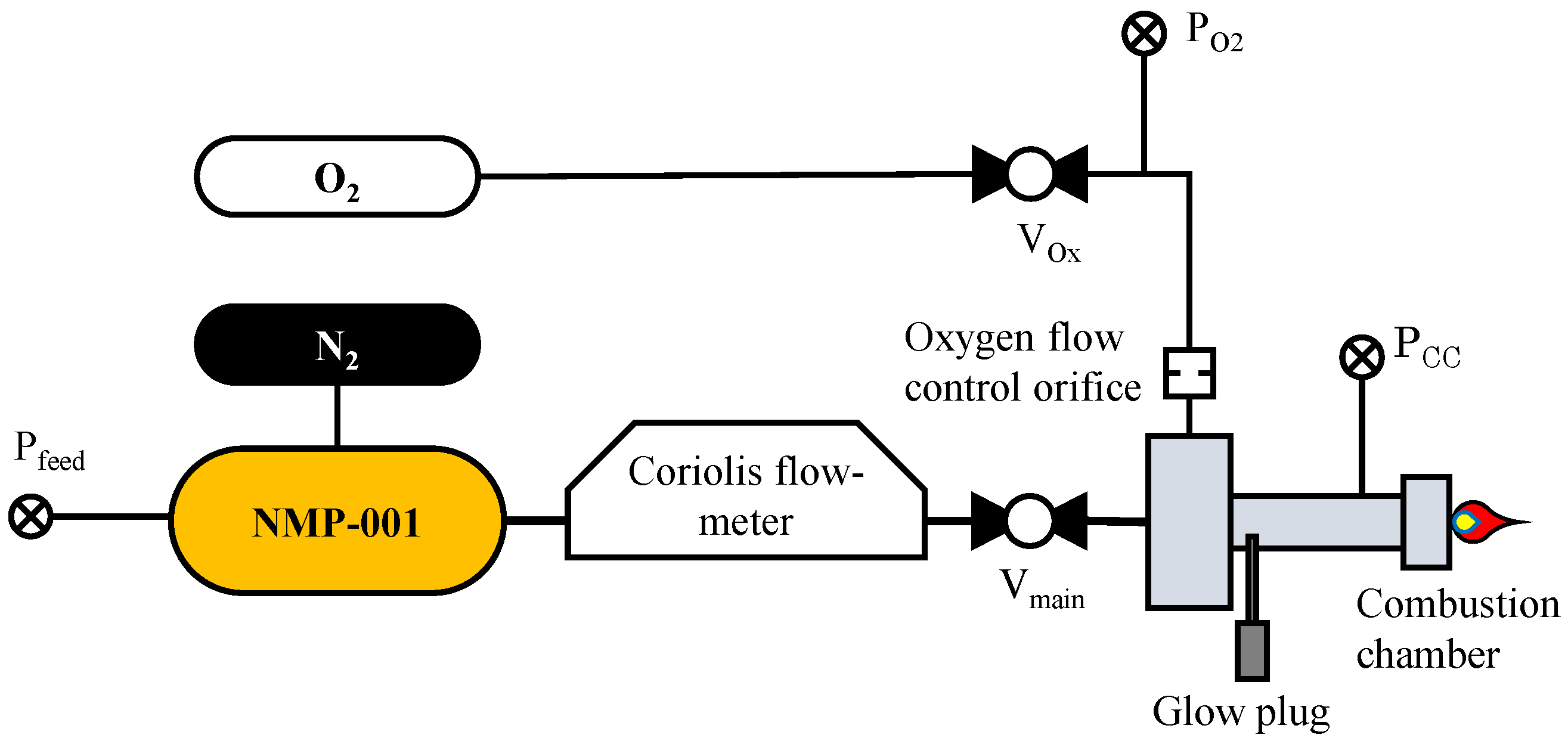
Figure 2 illustrates the test setup used in the presented test campaign. This test setup was implemented at the M11 test bench at the DLR Institute of Space Propulsion test center in Lampoldshausen, Germany. Data acquisition was performed using a PXI-based from National Instruments (Austin, TX, USA) system with amplifiers purchased from DEWETRON (Grambach, Austria). These amplifiers are capable of capturing data from up to 160 sensor channels at a sampling rate of up to 40 kHz. The test facility is equipped with a PLC (Programmable Logic Controller) acquired from Siemens (AG Munich, Germany) for control and watchdog purposes. The test bench also provided the oxygen for ignition and a nitrogen feed from reservoirs capable of pressures of up to 200 bar. The PLC also regulates the pressure of nitrogen and oxygen reservoirs, employing controllable dome pressure reducers.
Within this test setup, three 100 bar (full-scale) pressure transducers procured from STS Sensor Technik Sirnach AG (Sirnach, Switzerland), each with an uncertainty rating of ±0.5 bar, were used to assess the conducted tests. These sensors were used to measure the propellant feed pressure ( P feed ), the ignition oxygen pressure ( P O 2 ), and the pressure within the combustion chamber ( P c c ).
The NMP-001 formulation was prepared on site before being tested in 1 kg batches. For propellant preparation, 98.5% pure nitromethane and 99.8% pure dimethyl sulfoxide were purchased from Carl Roth GmbH + Co. KG (Karlsruhe, Germany) The used ferrocene was 98% pure and acquired from Sigma-Aldrich/Merck KGaA (Darmstadt, Germany). Each propellant batch was tested with a BAM Fallhammer device to reach a minimal impact sensitivity of 10 J. This requirement is rooted in the fact that NMP-001 is filled into 200 g bottles for fueling operations. These bottles weigh approximately 50 g. In the worst case, dropping a full bottle would result in an impact energy of 2.5 J. A factor of four was applied to these values to ensure safe operations. As discussed in the previous section, nitromethane may be particularly dangerous if enclosed in metal tubes or tanks. Therefore, preparatory operations before hot-fire tests, such as fueling and priming, were conducted remotely.
The propellant tank was pressurized with nitrogen to different pressure levels. This allowed for the investigation of different propellant mass flow rates and, thus, different chamber pressure load points. The propellant flow rate was determined by utilizing a RHM03L Coriolis flowmeter (Rheonik Messtechnik GmbH, Odelzhausen, Germany), calibrated to maintain an accuracy of at least 0.5% of the presently measured value. A 3D triplet impinging jet injector was used to inject the nitromethane-based monopropellants.
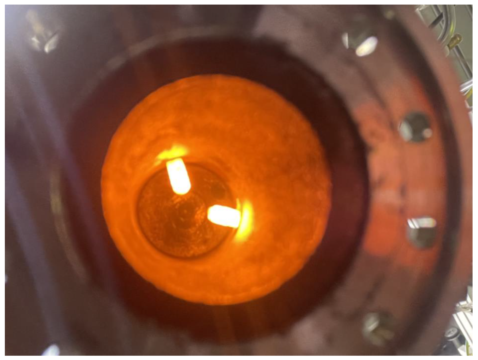
The oxygen required for the ignition procedure was injected into the combustion chamber from two orifices positioned at the injector face and slanted at 30° toward the chamber length axis (see Figure 3). In order to control the oxygen flow rate, an interchangeable metering orifice with a straight bore was used. The metering orifice was analyzed using a VHX-5000 microscope (KEYENCE, Neu-Isenburg, Germany). The measurement uncertainty of the orifice cross-section was expected to be within ±5% of the measured value. Before the test campaign, the discharge coefficient was derived with nitrogen to be 0.875 ± 0.057, which agrees well with the value for straight passages (0.85) published in [63].
Two CZ262 automotive glow plugs (NGK/Niterra EMEA GmbH, Ratingen, Germany, see Figure 3) were used as an ignition source in the pre-tests. However, during these tests, it was determined that a single glow plug was sufficient. Therefore, only one glow plug was used in all the tests presented here. The glow plug was operated at 12 V and underwent a 20-second preheating period before each test. Characterization tests were carried out before the test campaign. These tests showed that the glow plug surface reached a temperature of at least 900 °C after the preheating phase. The glow plugs were positioned 20 mm below the injector face and protruded 8 mm into the combustion chamber.
A stainless-steel battleship combustion chamber was utilized for the tests presented in this paper. The combustion chamber pressure sensor was installed towards the end of the straight section of the combustor. The wall temperature of the combustion chamber was measured using eleven 0.5 mm Type K thermocouples (Electronic Sensor GmbH, Heilbronn, Germany), with an accuracy of ±2.5 K. These sensors were positioned along the longitudinal axis of the combustion chamber. In order to ensure uniform contact with the chamber wall material, bores were made, stopping 1.0 ± 0.05 mm before the inner surface. The thermocouples were inserted into these bores and spring-loaded with a force of 2 N each. This methodology is based on an approach explained in detail by Suslov et al. [64].
In the first test series (S1), a CuCr1Zr nozzle was paired with the chamber. Similarly to in the experiments described in [29], the nozzle throat experienced erosion. The resulting change of the critical nozzle cross-section caused the characteristic length ( L * = V c h a m b e r / A t h r o a t ) to fluctuate between 7.8 and 6.2 m. Therefore, measuring the nozzle throat diameter after each test was necessary to calculate the combustion efficiency accurately. These measurements were carried out using gauges with a diameter spacing of 0.02 mm. In the subsequent test series (S2 and S3), a molybdenum alloy (TZM) nozzle was used, effectively resolving the nozzle erosion issue. In test series S2, the characteristic length L * was fixed at 8.4 m.
Dynamic thermally induced changes are another source of uncertainty in the nozzle throat geometry. Consequently, the nozzle throat diameter was expected to vary by up to ±0.04 mm in each test. These variations were included in the uncertainty analysis, as will be discussed later.
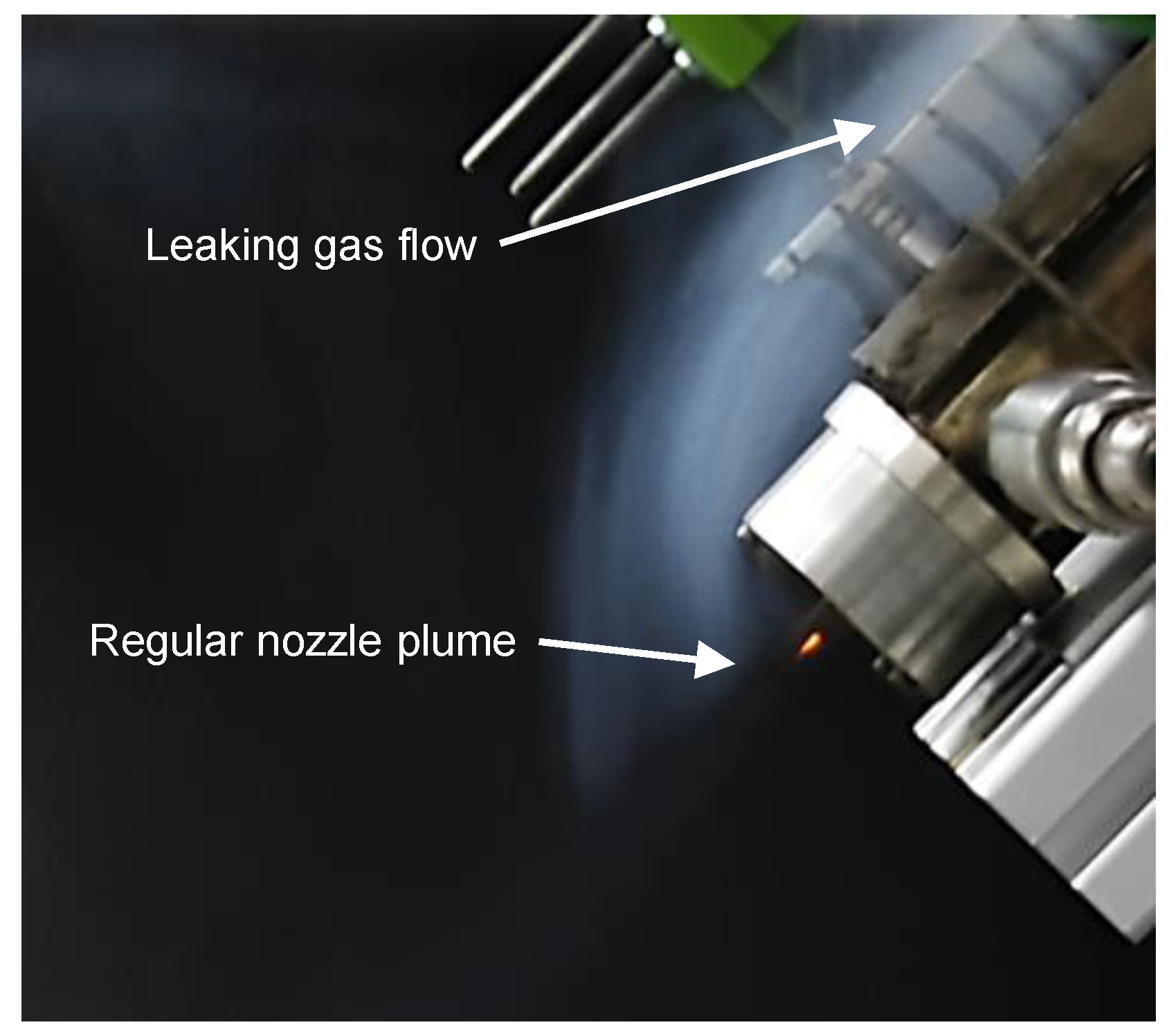
Additionally, after thoroughly analyzing the test videos of test series S2, leaks in the combustion chamber were detected (see Figure 4). These leaks were caused by microscopic cracks at the bottom of the bores where the front three thermocouples were inserted. It is assumed that these cracks were introduced by thermal cycling. To quantify the leakage caused by these cracks, they were measured once again using the VHX-5000 microscope after the test campaign was finished. The approximate throughput area of each of the three cracks was found to be equivalent to a hole with a diameter of no more than 0.1 mm in each case. Thus, the effect of these cracks could be reflected in the error indicators in the diagrams presented in the next chapter.
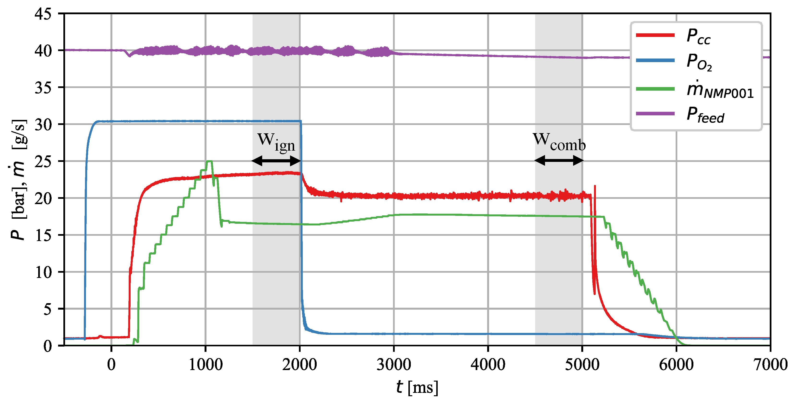
Figure 5 illustrates the test procedure and the positioning of the analysis windows. After preheating the glow plugs for 20 s, the oxygen valve ( V O 2 ) was opened in order to precondition the atmosphere in the chamber. In all tests of this campaign, the oxygen valve was opened at t = 300 ms, which resulted in the oxygen entering the combustion chamber at t = 280 ms. Then, at t = 0 , the main propellant valve ( V main ) was opened. Shortly after that, ignition occurred. In order to achieve results comparable to those of the tests described in [29], which were conducted with an H2/O2 torch igniter, the oxygen valve was left open for 2 seconds, exactly as in that test campaign. After the ignition phase, i.e., after t = 2000 ms, monopropellant combustion continued until the main propellant valve was closed at t = 5000 ms or if a redline was triggered.
Two analysis windows were used to evaluate the ignition and combustion phases. The ignition analysis window w ign was 500 ms long and was positioned at the end of the ignition phase, i.e., between t = 1500 and t = 2000 ms. The combustion performance evaluation window w comb , also 500 ms long, was located shortly before closing the propellant valve, i.e., between t = 4500 and t = 5000 ms in regular tests. In tests where a flameout occurred before t = 5000 ms, the window w c o m b was placed just before the flameout. In cases where the flameout occurred less than 500 ms after switching off the oxygen, w c o m b was shortened accordingly.
The evaluation methodology presented in this paper is similar to the one used for analyzing the tests presented in [29]. Firstly, it was determined whether a test run was stable. However, more simplified evaluation criteria were used for this metric than in the previous analysis. A test was considered stable if no flameout occurred between t = 2000 and t = 5000 ms. This was only possible if no redlines, which ensure that the chamber pressure remains within ±10% of the expected value, were triggered. Note that the redlines were defined in such a way that non-systematic short-term deviations of up to 50 ms caused by measurement artifacts or short-lived phenomena could be tolerated.
In the second step, derived quantities such as the ROF during the ignition phase and the monopropellant combustion efficiency were calculated and assessed. For calculating the ROF, the window w i g n was used. In this analysis window, ROF is defined by the following equation:
R O F = m ˙ O 2 ,   w i g n m ˙ N M P ,   w i g n
m ˙ O 2 ,   w i g n : Average oxygen mass flow rate inside w i g n ,   [ kg / s ] ; m ˙ N M P ,   w i g n : Average NMP mass flow rate inside w i g n ,   [ kg / s ] .
The uncertainties introduced by the Coriolis flow meter, the oxygen metering orifice, the discharge coefficient, and the pressure transducers led to a combined uncertainty for the ROF of up to ±0.11. This value was calculated with the error propagation method described in [65,66].
For calculating the combustion efficiency, the window w c o m b was used. This parameter is defined by Equation (2). The theoretical characteristic velocity C C E A * was computed by the NASA CEA tool [24] using equilibrium flow and the averaged combustion chamber pressure in the window w c o m b . Then, this value was compared to the one achieved in the test, which was calculated by Equation (3).
η C * = C t e s t * C C E A *
C t e s t * = P c c ,   w c o m b m ˙ N M P ,   w c o m b π d t 2 4
C t e s t * : Measured characteristic velocity , [ m / s ] ; P c c ,   w c o m b : Average chamber pressure in w c o m b , [ MPa ] ; m ˙ N M P ,   w c o m b : Average NMP mass flow inside w c o m b , [ kg / s ] ; d t : Nozzle throat diameter , [ mm ] ; η C * : Combustion efficiency , [ % ] ; C C E A * : Calculated characteristic velocity , [ m / s ] .
Similarly to the ROF, the C * -values, and thus the combustion efficiency η C * , were subject to uncertainties. These were rooted in the uncertainties discussed above that stemmed from propellant mass flow, pressure measurements, and nozzle throat region geometry changes. Combined, these influences led to deviations of between + 7 and 10 % . The diagrams presented in the next section reflect these uncertainties through error indicators.
Each experiment was repeated at least twice to achieve reliable and repeatable results. The most critical experiments, namely those defining the low-pressure combustion limit identified in test series S2 and those determining the “go-no/go” state for reliable ignition in test series S3, were repeated three to four times.

3. Results and Discussion

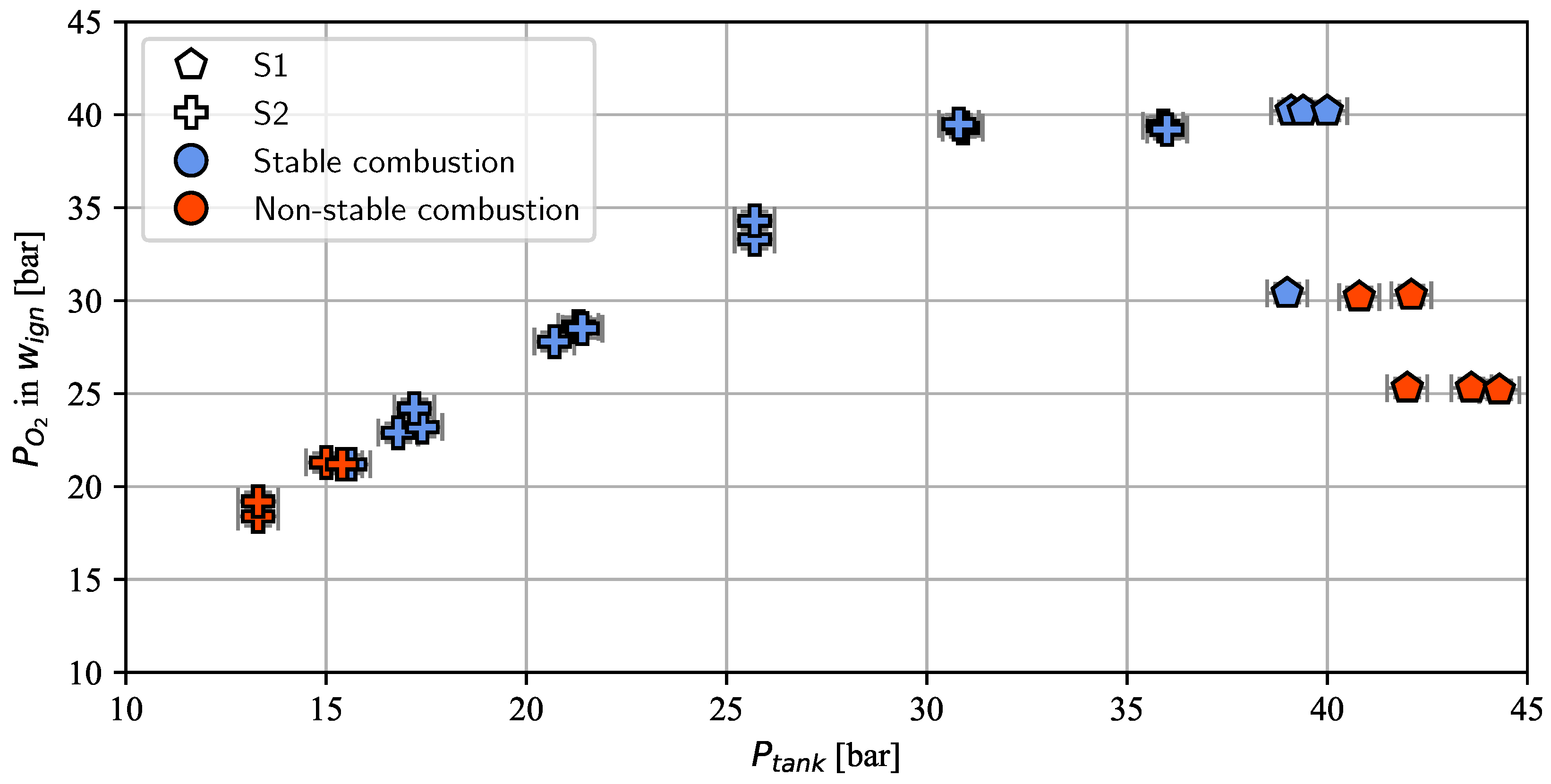
In Figure 6, the stable and non-stable working points for the test series S1 and S2 are shown. Test series S1 was started at a feed pressure of 40 to 45 bar. This feed pressure was expected to yield a chamber pressure of 20 to 22 bar, a value well inside the stable combustion region for a characteristic length L * of 7.8 m, as identified in [29]. It also is known that an oxygen pressure of 40 bar or above produces reliable ignition with the H2/O2 torch. However, in this test campaign, it was decided to start at a lower pressure level and increase the oxygen pressure incrementally. Nevertheless, successful ignition was only achievable with an oxygen pressure setting of around 40 bar for a propellant feed pressure of 40 bar. As depicted by Figure 7, this load point corresponded to an ROF of 0.3 inside w i g n . Therefore, an ROF of 0.3 was considered the minimum for successful ignition.
Test series S2 was started at a load point that produced a chamber pressure of 17 bar (see Figure 7). This value is near the known minimal chamber pressure of 16.5 bar identified in [29] for a similar characteristic length of L * . In order to prevent hard starts, i.e., to achieve a reliable ignition in any case, the ROF for test series S2 was always kept slightly higher than 0.3.
As expected, the P C C = 17 bar load point led to stable combustion in all cases. Unexpectedly, however, a further decrease in propellant feed pressure still resulted in stable combustion. The chamber operation became non-stable only when the combustion pressure fell below 13 bar. The average chamber pressure of the three stable loading points defining the low-pressure operation limit was 13.9 bar.
The lowest stable operation point reliably achieved in [29] was achieved in test series C1 at 15.1 bar, albeit at a much higher characteristic length of L * , which was a quantity found to play a crucial role in enabling stable combustion at low chamber pressures with NMP-001. In test series C3, which was carried out with a similar characteristic length to test series S2 presented in this paper, only a low-pressure operation limit of 16.6 bar could be demonstrated.
The cause of the lower low-pressure combustion limit with the new ignition procedure remains undetermined. Notably, it is peculiar that, despite a lesser temperature gain Δ T w ,   i g n during the ignition phase in test series S2 compared to test series C1 and C3 from [29], successful ignition was still possible. Moreover, in S2, stable combustion was more stable at lower pressures, as shown in Table 2.
After successfully identifying the low-pressure combustion limit for test series S2, further tests were carried out to characterize combustion at higher pressure levels. Combustion pressure load points of up to 27 bar were investigated.
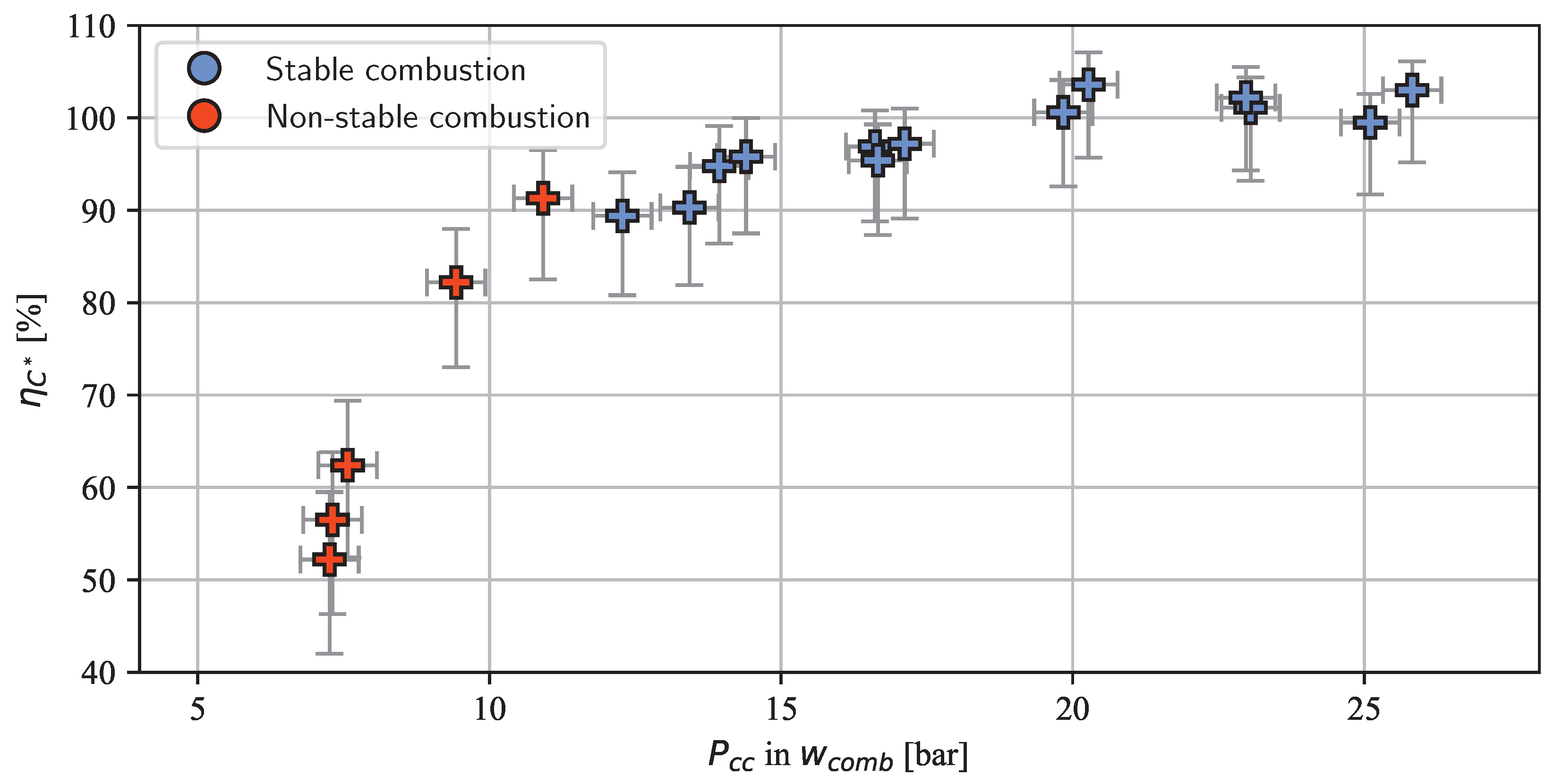
Figure 8 shows the combustion efficiency achieved in the S2 tests. As expected, this metric increased with rising combustion chamber pressure. This phenomenon can be attributed to the pressure-dependent combustion mechanism of nitromethane, as empirically demonstrated by Kelzenberg et al. and Boyer and Kuo [45,50,67] and qualitatively explained by Yetter et al. [60] and Shrestha et al. [61]. Note that some tests exhibited a combustion efficiency exceeding 100%. As discussed in Section 2, this anomaly was caused by cracks in the chamber wall, which effectively created a larger throat area. Consequently, the actual combustion efficiency is anticipated to be lower than 100% but not lower than indicated by the error bars as the crack size was analyzed and taken into account.
To conclude, the combustion at the low-pressure operation limit of S2 was measured to be in the lower 80 to lower 90% range. At pressures above 17 bar, the efficiency was above 95%, which equals a characteristic velocity C * of above 1310 m/s. This value is slightly higher than 1300 m/s, which is the characteristic velocity a 95%-efficient LMP-103S thruster would theoretically produce at the same chamber pressure (NASA CEA [24] calculation at 17 bar assuming chemical equilibrium at the combustion point).
As stated earlier, the goal of test series S3 was to optimize the newly developed ignition method. This method does not require prolonged and power-intensive preheating of the combustion chamber and catalyst pack nor expensive materials for the active phase of the catalyst or the catalyst support structure, as is the case for ADN- and HAN-based propellants (see [20,22,23]). However, an oxygen source is necessary for successful ignition. Therefore, minimizing the amount of oxygen required to achieve ignition was crucial.
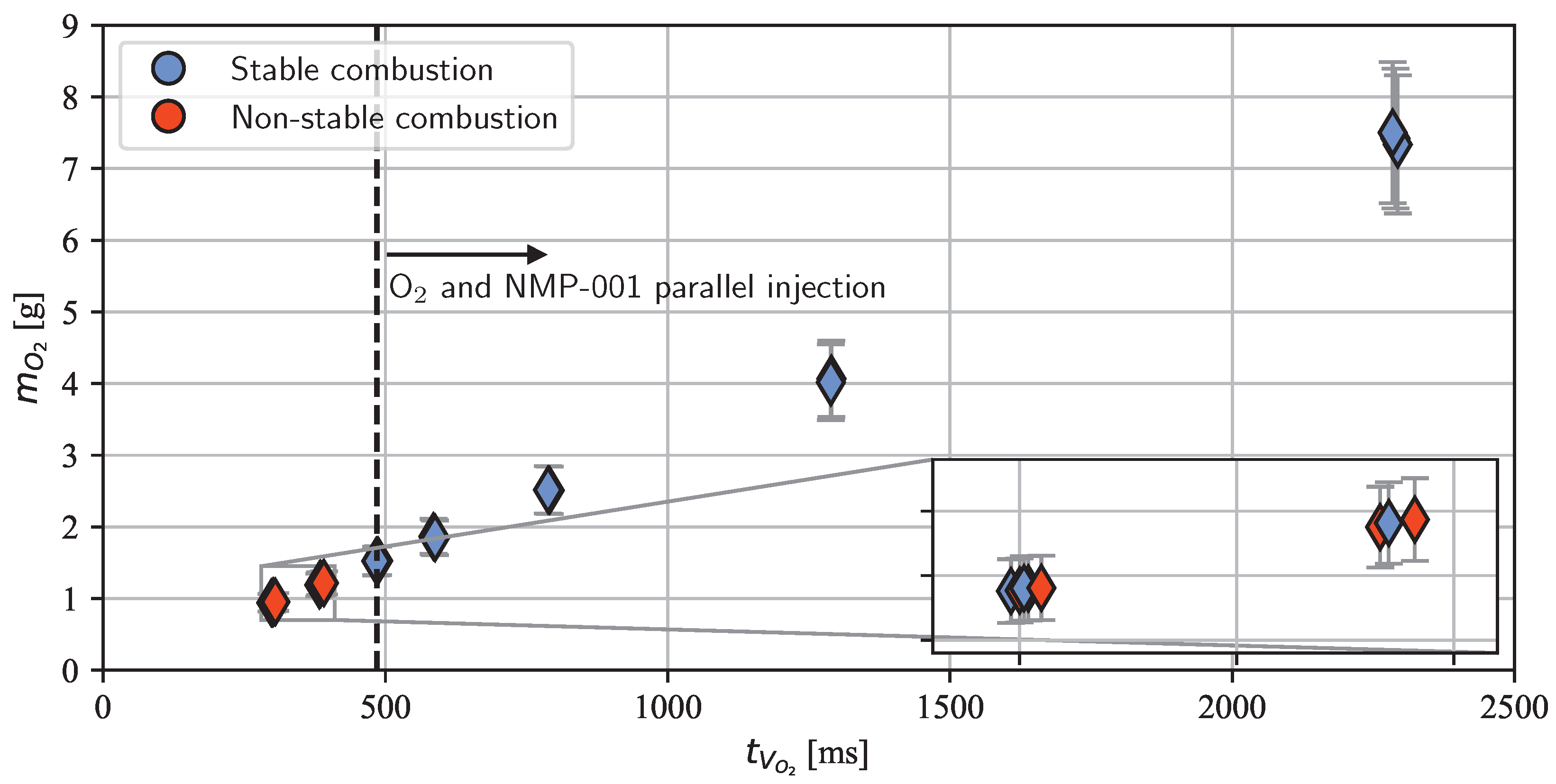
In test series S3, the opening duration of the oxygen valve was varied to investigate the influence of the amount of injected oxygen on ignition and combustion. A working point that consistently yielded efficient combustion at chamber pressures of 16.5 to 17 bar in test series S2 was used in these tests. Similarly, as in S2, the ROF was kept between 0.35 and 0.4 in all S3 tests. Figure 9 delineates the influence of the valve opening time t V O 2 and the injected oxygen mass m O 2 on combustion stability.
As with all the other experiments presented in this study, the tests in S3 were operated under an oxygen lead. In the test series S1 and S2 tests, oxygen was switched on and off at t = 280 and t = 2009 , respectively. The injection of NMP-001 into the combustion chamber occurred sometime between t = 0 , when the main propellant valve V m a i n was operated, and the time of ignition t i g n , which is defined as the time of the chamber pressure rise onset, shown in Figure 5. Consequently, the injection of NMP-001 and oxygen took place in parallel in all S1 and S2 tests. This was also true for the first load points tested in test series S3. All tests carried out with a parallel injection yielded stable combustion in this test series. During the test series, it was possible to reduce the oxygen injection time from 2300 ms to 485 ms, representing a reduction from 7.4 to 1.5 g of total injected oxygen. Moreover, even when the combustion chamber was merely flooded with oxygen for 300 to 390 ms, successful ignition and stable combustion were possible in three of eight tests (see inset in Figure 9). The reduction in the amount of total injected oxygen did not affect the combustion efficiency during the monopropellant operation phase. In all tests of test series S3 with a reduced oxygen valve opening time, the average combustion efficiency was 95%.
To conclude, even though the developed ignition approach does not work entirely without oxygen, the required amount can be significantly reduced. This oxygen can be used for other applications to reduce the system footprint. For instance, since injecting this gas is required, it could be used as a cold-gas propellant to settle the liquid propellant in the tank after a coasting phase. The required oxygen can also be used to pressurize the nitromethane-based monopropellant tank.
Furthermore, the developed ignition device eliminates the need for an expensive catalyst pack and does not require a prolonged preheating procedure, essentially providing a cold-start capability. However, the glow plug used requires 9 to 14 A for operation at 12 V. This is an extensive requirement for a satellite or spacecraft and therefore requires further optimization.

4. Conclusions

This paper presents three test series to characterize a newly developed ignition system for nitromethane-based propellants. This system utilizes a glow plug as the source of ignition. Additionally, a small amount of gaseous oxygen floods the combustion chamber before the monopropellant is injected, creating favorable ignition conditions. For a brief period after the beginning of the propellant injection, the oxygen is still supplied to the combustion chamber to generate a pilot flame. After the oxygen injection is terminated, monopropellant combustion follows. This system was evaluated and optimized in rocket combustion chamber tests using NMP-001, an already well-characterized propellant.
All three set goals were satisfied. The first goal was to determine the required oxygen-to-NMP-001 mass ratio to generate a guaranteed ignition. This metric was determined to be above 0.3 during the ignition phase. Values below 0.3 did not always produce stable monopropellant combustion after the ignition phase. The second goal was to characterize the low-pressure combustion margin of NMP-001 with the novel ignition method. The new ignition system produced a lower low-pressure operation limit than tests with the H2/O2 torch used in previous work. Stable combustion was possible at a chamber pressure of 13.9 bar instead of 15.1 bar. The last goal was to optimize the ignition procedure by reducing the required amount of oxygen. Compared to initial tests, the required amount of oxygen was reduced by a factor of approximately four.
Moreover, the ignition device tested in the hot-fire campaign presented in this paper offers advantages compared to heated catalyst bed ignition systems used in hydrazine, hydrogen peroxide, and ADN- and HAN-based propulsion. The virtually non-existent preheating time required to achieve reliable ignition is a meaningful benefit, providing a cold-start capability. However, the glow plug used in this system draws a current of 10–14 A, which is a considerable power requirement for a satellite and thus necessitates further development. Additionally, the system relies on oxygen for ignition, which increases the propulsion system’s footprint. An approach to mitigate this is to use the oxygen required for ignition as a pressurizing agent for the propellant. As the thrusters also operate under an oxygen lead, a mode in which oxygen is injected into the combustion chamber before the propellant, the oxygen may also be used as a cold-gas propellant to settle the main propellant after prolonged coasting in microgravity.
Moreover, using a widely available gas for ignition, rather than a heated catalyst composed of expensive materials such as Pt and Ir, as in the Shell 405 catalyst used in hydrazine thrusters, holds significant potential for cost savings compared to hydrazine, hydrogen peroxide, and HAN- and ADN-based propulsion systems.

Author Contributions

Conceptualization, M.K., C.U.K. and S.S.; methodology, software, validation, formal analysis, investigation, data curation, writing—original draft preparation, visualization, project administration: M.K.; funding acquisition, resources, supervision, writing—review and editing: C.U.K. and S.S. All authors have read and agreed to the published version of the manuscript.

Funding

This research received no external funding.

Data Availability Statement

The datasets presented in this article are not readily available because of export restrictions due to the sensitive nature of the experiments and generated data. Requests to access the datasets should be directed to the corresponding author.

Conflicts of Interest

The authors declare no conflicts of interest. The funders had no role in the design of the study; in the collection, analyses, or interpretation of data; in the writing of the manuscript; or in the decision to publish the results.

Abbreviations

The following abbreviations are used in this manuscript:
ADNAmmonium dinitramide
HANHydroxylammonium nitrate
NMP-001Nitromethane monopropellant 001
PLCProgrammable Logic Controller
ROFOxygen-to-NMP-001 mass ratio
C C E A * Calculated characteristic velocity, [m/s]
C t e s t * Measured characteristic velocity, [m/s]
d t Nozzle throat diameter, [mm]
L * Characteristic combustion chamber length, [m]
m ˙ N M P ,   w c o m b NMP mass flow rate inside w c o m b , [g/s]
m ˙ N M P ,   w i g n NMP mass flow rate inside w i g n , [g/s]
m ˙ O 2 ,   w i g n Oxygen mass rate flow inside w i g n , [g/s]
P c c Combustion chamber pressure, [bar]
P c c ,   w c o m b Average chamber pressure in w c o m b , [bar]
P feed Propellant tank feed pressure, [bar]
P O 2 Ignition oxygen pressure, [bar]
η C * Combustion efficiency, [%]

References

  1. Brown, C.D. Spacecraft Propulsion; AIAA: Las Vegas, NV, USA, 1996. [Google Scholar]
  2. Sutton, G.P.; Biblarz, O. Rocket Propulsion Elements, 8th ed.; John Wiley & Sons: Hoboken, NJ, USA, 2010. [Google Scholar]
  3. Sarritzu, A.; Felix, L.; Lukas, W.; Pasini, A. Assessment of Propulsion System Architectures for Green Propellants-based Orbital Stages. In Proceedings of the International Astronautical Congress: IAC Proceedings, Paris, France, 8–22 September 2022; IAF (International Astronautical Federation): New Delhi, India, 2022. [Google Scholar]
  4. National Center for Biotechnology Information. PubChem Compound Summary for CID 9321, Hydrazine. 2024. Available online: https://pubchem.ncbi.nlm.nih.gov/compound/Hydrazine (accessed on 30 August 2024).
  5. European Chemicals Agency. Substance Infocard—Hydrazine. 2024. Available online: https://echa.europa.eu/de/substance-information/-/substanceinfo/100.005.560 (accessed on 29 August 2024).
  6. MacLean, M.; Rodriguez, H. A low-risk, reliable, operationally efficient auxiliary propulsion system for the Reusable Launch Vehicle. In Proceedings of the 32nd Joint Propulsion Conference and Exhibit, Lake Buena Vista, FL, USA, 1–3 July 1996; p. 3228. [Google Scholar]
  7. Marshall, W.M.; Deans, M.C. Recommended figures of merit for green monopropellants. In Proceedings of the 49th AIAA/ASME/SAE/ASEE Joint Propulsion Conference, San Jose, CA, USA, 15–17 July 2013; p. 3722. [Google Scholar]
  8. Bombelli, V.; Simon, D.; Moerel, J.L.; Marée, T. Economic benefits of the use of non-toxic mono-propellants for spacecraft applications. In Proceedings of the 39th AIAA/ASME/SAE/ASEE Joint Propulsion Conference and Exhibit, Huntsville, AL, USA, 20–23 July 2003; p. 4783. [Google Scholar]
  9. Masse, R.; Allen, M.; Spores, R.; Driscoll, E.A. AF-M315E propulsion system advances and improvements. In Proceedings of the 52nd AIAA/SAE/ASEE Joint Propulsion Conference, Salt Lake City, UT, USA, 25–27 July 2016; p. 4577. [Google Scholar]
  10. Gohardani, A.S.; Stanojev, J.; Demairé, A.; Anflo, K.; Persson, M.; Wingborg, N.; Nilsson, C. Green space propulsion: Opportunities and prospects. Prog. Aerosp. Sci. 2014, 71, 128–149. [Google Scholar] [CrossRef]
  11. Wingborg, N.; Larsson, A.; Elfsberg, M.; Appelgren, P. Characterization and ignition of ADN-based liquid monopropellants. In Proceedings of the 41st AIAA/ASME/SAE/ ASEE Joint Propulsion Conference & Exhibit, Tucson, AZ, USA, 10–13 July 2005; p. 4468. [Google Scholar]
  12. Wingborg, N.; Johansson, M.; Bodin, L. Initial Development of a Laboratory Rocket Thruster for ADN-Based Liquid Monopropellants; Swedish Defence Research Agency: Stockholm, Sweden, 2006.
  13. Larsson, A.; Wingborg, N. Green propellants based on ammonium dinitramide (ADN). Adv. Spacecr. Technol. 2011, 2, 139–156. [Google Scholar]
  14. Persson, M.; Anflo, K.; Friedhoff, P. Flight heritage of ammonium dinitramide (ADN) based high performance green propulsion (HPGP) systems. Propellants Explos. Pyrotech. 2019, 44, 1073–1079. [Google Scholar] [CrossRef]
  15. Amrousse, R.; Katsumi, T.; Azuma, N.; Hori, K. Hydroxylammonium nitrate (HAN)-based green propellant as alternative energy resource for potential hydrazine substitution: From lab scale to pilot plant scale-up. Combust. Flame 2017, 176, 334–348. [Google Scholar] [CrossRef]
  16. Hori, K.; Katsumi, T.; Sawai, S.; Azuma, N.; Hatai, K.; Nakatsuka, J. HAN-Based Green Propellant, SHP163–Its R&D and Test in Space. Propellants Explos. Pyrotech. 2019, 44, 1080–1083. [Google Scholar]
  17. Katsumi, T.; Hori, K. Successful development of HAN based green propellant. Energetic Mater. Front. 2021, 2, 228–237. [Google Scholar] [CrossRef]
  18. Chai, W.S.; Cheah, K.H.; Wu, M.H.; Koh, K.S.; Sun, D.; Meng, H. A review on hydroxylammonium nitrate (HAN) decomposition techniques for propulsion application. Acta Astronaut. 2022, 196, 194–214. [Google Scholar] [CrossRef]
  19. Masse, R.K.; Spores, R.; Allen, M. AF-M315E advanced green propulsion–GPIM and beyond. In Proceedings of the AIAA Propulsion and Energy 2020 Forum, Virtual. 24–26 August 2020; p. 3517. [Google Scholar]
  20. Gonzalez Rueda Flores, P.; Cuevas, R.A.; Rahman, A.; Zubia, R.A.; Tobias, E.A.; Adams, S.C.; Ontiveros, N.; Quintana, J.; Greig, A.D.; Choudhuri, A.R. Implementing Test Methodology Improvements for Testing and Validation of a 1N AF-M315E Thruster. In Proceedings of the AIAA Propulsion and Energy 2021 Forum, Virtual. 9–11 August 2021; p. 3590. [Google Scholar]
  21. Kilcoin, M.; Cavender, D.; Hasanof, T.; Zaluki, M.; McKechnie, T.; Sedano, C.; Williams, H. Development of ASCENT propellant thrusters and propulsion systems. In Proceedings of the 36th Annual AIAA/USU Conference on Small Satellites, Propulsion, SSC22-X-08, Logan, UT, USA, 11–13 August 2022. [Google Scholar]
  22. Maleix, C.; Chabernaud, P.; Brahmi, R.; Beauchet, R.; Batonneau, Y.; Kappenstein, C.; Schwentenwein, M.; Koopmans, R.J.; Schuh, S.; Scharlemann, C. Development of catalytic materials for decomposition of ADN-based monopropellants. Acta Astronaut. 2019, 158, 407–415. [Google Scholar] [CrossRef]
  23. Negri, M.; Wilhelm, M.; Hendrich, C.; Wingborg, N.; Gediminas, L.; Adelöw, L.; Maleix, C.; Chabernaud, P.; Brahmi, R.; Beauchet, R.; et al. New technologies for ammonium dinitramide based monopropellant thrusters–The project RHEFORM. Acta Astronaut. 2018, 143, 105–117. [Google Scholar] [CrossRef]
  24. Gordon, S.; McBride, B.J. Computer Program for Calculation of Complex Chemical Equilibrium Compositions and Applications. Part 1: Analysis; Technical Report; NASA Lewis Research Cente: Cleveland, OH, USA, 1994.
  25. Price, T.; Evans, D. The status of Monopropellant Hydrazine Technology; Technical Report; Jet Propulsion Laboratory, NASA: Pasadena, CA, USA, 1968.
  26. Pasini, A.; Sales, L.; Puccinelli, E.; Lin, L.; Apollonio, A.; Simi, R.; Brotini, G.; d’Agostino, L. Design of an Affordable Hydrogen Peroxide Propulsion System for CubeSats. In Proceedings of the AIAA Propulsion and Energy 2021 Forum, Virtual. 9–11 August 2021; p. 3690. [Google Scholar]
  27. German, B.J.; Branscome, E.C.; Frits, A.P.; Yiakas, N.C.; Mavris, D.N. An evaluation of green propellants for an ICBM post-boost propulsion system. In Proceedings of the Missile Sciences Conference, Monterey, CA, USA, 5–7 November 2000. [Google Scholar]
  28. Davis, D.D.; Dee, L.; Greene, B.; Hornung, S.; McClure, M.; Rathgeber, K. Fire, Explosion, Compatibility and Safety Hazards of Hydrogen Peroxide; National Aeronautics and Space Administration NASA TM-2004-213151; NASA: Washington, DC, USA, 2005.
  29. Kurilov, M.; Werling, L.; Kirchberger, C.; Ciezki, H.; Schlechtriem, S. Combustion behavior of NMP-001, a nitromethane-based green rocket propellant. Acta Astronaut. 2024, 223, 1–14. [Google Scholar] [CrossRef]
  30. Markofsky, S.B. Nitro compounds, aliphatic. Ullmann’s Encycl. Ind. Chem. 2000, 24, 291–300. [Google Scholar]
  31. National Center for Biotechnology Information. PubChem Compound Summary for CID 6375, Nitromethane. 2024. Available online: https://pubchem.ncbi.nlm.nih.gov/compound/Nitromethane (accessed on 27 August 2024).
  32. U.S. Department of Defense. Performance specification - Propellant, Hydrazine, MIL-PRF-26536F.; 2011. Available online: http://everyspec.com/MIL-PRF/MIL-PRF-010000-29999/MIL-PRF-26536F_32241/ (accessed on 27 August 2024).
  33. Lide, D.R. CRC Handbook of Chemistry and Physics; CRC Press: Boca Raton, FL, USA, 2004; Volume 85. [Google Scholar]
  34. U.S. Defence Logistics Agency. Standard Prices for Aerospace Products.; 2024. Available online: https://www.dla.mil/Energy/Business/Standard-Prices/ (accessed on 25 August 2024).
  35. Wingborg, N. Heat of Formation of ADN-Based Liquid Monopropellants. Propellants Explos. Pyrotech. 2019, 44, 1090–1095. [Google Scholar] [CrossRef]
  36. Anflo, K.; Möllerberg, R. Flight demonstration of new thruster and green propellant technology on the PRISMA satellite. Acta Astronaut. 2009, 65, 1238–1249. [Google Scholar] [CrossRef]
  37. Gotzig, U. Challenges and economic benefits of green propellants for satellite propulsion. In Proceedings of the 7th European Conference for Aeronautics and Space Sciences (EUCASS), Milan, Italy, 3–6 July 2017. [Google Scholar]
  38. Digital Solid State Propulsion Inc. AF-M315E Safety Data Sheet. 2024. Available online: https://static1.squarespace.com/static/59de9c9c18b27ddf3bac610a/t/5e3af2d0fb8df43f9b2ae377/1580921553250/AF-M315E+SDS.pdf (accessed on 24 August 2024).
  39. Digital Solid State Propulsion Inc. Chemicals and Propellants—AF-M315E Pricing. 2024. Available online: https://dssptech.com/propellant-products (accessed on 24 August 2024).
  40. Evonik Operations GmbH. Aeornautic Applications Brochure. 2024. Available online: https://active-oxygens.evonik.com/zh/attachment/140277?rev=9a24167032bd618d7f7ff672a62fa152 (accessed on 24 August 2024).
  41. Evonik Active Oxygens, LLC. Hydrogen Peroxide Physico-Chemical Properties. 2024. Available online: https://active-oxygens.evonik.com/en/products-and-services/hydrogen-peroxide/general-information/physico-chemical-properties (accessed on 24 August 2024).
  42. Jarosiewicz, M.; Szychlinski, J. Gas chromatographic determination of impurities in nitromethane. Chromatographia 1980, 13, 35–39. [Google Scholar] [CrossRef]
  43. House, W.C. Project SQUID. In Liquid Propellant Rockets, Volume II, Part 2; Filed Survey Report; Princeton University: Princeton, NJ, USA, 1947; pp. 48–50. [Google Scholar]
  44. Clark, J.D. Ignition!: An Informal History of Liquid Rocket Propellants; Rutgers University Press: New Brunswick, NJ, USA, 1972. [Google Scholar]
  45. Boyer, E.; Kuo, K. Characteristics of nitromethane for propulsion applications. In Proceedings of the 44th AIAA Aerospace Sciences Meeting and Exhibit, Reno, NV, USA, 9–12 January 2006; p. 361. [Google Scholar]
  46. Makovky, A.; Lenji, L. Nitromethane-physical properties, thermodynamics, kinetics of decomposition, and utilization as fuel. Chem. Rev. 1958, 58, 627–644. [Google Scholar] [CrossRef]
  47. Hermoni, A. Role of rate of decomposition of nitric oxide in the use of nitromethane as a monopropellant. J. Appl. Chem. 1959, 9, 420–422. [Google Scholar] [CrossRef]
  48. Benziger, J.B. Decomposition of Nitromethane over NiO and Cr2O3 Catalysts. Combust. Sci. Technol. 1982, 29, 191–205. [Google Scholar] [CrossRef]
  49. Benziger, J.B. A mechanistic study of nitromethane decomposition on nickel. Appl. Surf. Sci. 1984, 17, 309–323. [Google Scholar] [CrossRef]
  50. Kelzenberg, S.; Eisenreich, N.; Eckl, W.; Weiser, V. Modelling nitromethane combustion. Propellants Explos. Pyrotech. 1999, 24, 189–194. [Google Scholar] [CrossRef]
  51. Zoll, E.J.J.; Foster, J.W.; Hodges, E.S.; James, G.R.J.; Pefferle, F.R.; Egan, R.M.; Greenwald, C.W.; Heckenkamp, R.G.; Hart, T.B.; Thompson, C.; et al. Accident at Mt. Pulaski, Ill., on June 1 1958 Caused by the Explosion of a Tank Car Loaded with Nitromethane; Technical Report; Interstate Commerce Comission: Washington, DC, USA, 1958. [Google Scholar]
  52. Minato, R.; Tanaka, S. Fluid hammer phenomena for Nitromethane propellant feed system. Sci. Technol. Energetic Mater. 2022, 83, 111–116. [Google Scholar]
  53. Campbell, A.; Malin, M.; Holland, T. Temperature effects in the liquid explosive, nitromethane. J. Appl. Phys. 1956, 27, 963. [Google Scholar] [CrossRef]
  54. Bellinger, F.; Friedman, H.; Bauer, W.; Eastes, J.; Bull, W. Chemical Propellants. Stability of Mononitromethane. Ind. Eng. Chem. 1948, 40, 1320–1323. [Google Scholar] [CrossRef]
  55. Kusakabe, M.; Fujiwara, S. Effects of liquid diluents on detonation propagation in nitromethane. In Proceedings of the Sixth Symposium on Detonation, Coronado, CA, USA, 24–27 August 1976; pp. 133–142. [Google Scholar]
  56. Ananin, A.V.; Koldunov, S.A.; Garanin, V.V.; Sosikov, V.A.; Torunov, S.I. Shock wave sensitivity of nitromethane mixtures with nonexplosive liquids. Int. J. Energetic Mater. Chem. Propuls. 2013, 12, 87–94. [Google Scholar] [CrossRef]
  57. Kurilov, M.; Werling, L.; Negri, M.; Kirchberger, C.; Schlechtriem, S. Impact Sensitivity of Nitromethane-based Green-propellant Precursor Mixtures. Int. J. Energetic Mater. Chem. Propuls. 2023, 22, 35–43. [Google Scholar] [CrossRef]
  58. Klein, S.; Kurilov, M. Fluid hammer phenomena in a nitromethane-based green propellant in hot gas test runs. In Proceedings of the Space Propulsion Conference 2024, Glasgow, UK, 23 May 2024. [Google Scholar]
  59. Kindsvater, H.; Kendall, K.; Mueller, K.; Datner, P. Research on Nitromethane; Aeroject Engineering Cooperation, Report; Aeroject Engineering Cooperation: Rancho Cordova, CA, USA, 1951. [Google Scholar]
  60. Yetter, R.A.; Yang, V.; Wu, M.H.; Wang, Y.; Milius, D.; Aksay, I.A.; Dryer, F.L. Combustion issues and approaches for chemical microthrusters. Int. J. Energetic Mater. Chem. Propuls. 2007, 6, 393–424. [Google Scholar] [CrossRef]
  61. Shrestha, K.P.; Vin, N.; Herbinet, O.; Seidel, L.; Battin-Leclerc, F.; Zeuch, T.; Mauss, F. Insights into nitromethane combustion from detailed kinetic modeling–Pyrolysis experiments in jet-stirred and flow reactors. Fuel 2020, 261, 116349. [Google Scholar] [CrossRef]
  62. Kurilov, M.; Ziemer, L.; Weiser, V.; Ricker, S.; Kirchberger, C.; Schlechtriem, S. Ignition of Nitromethane-based Propellant Mixtures. Int. J. Energetic Mater. Chem. Propuls. 2024, 23, 53–67. [Google Scholar] [CrossRef]
  63. Kayser, J.C.; Shambaugh, R.L. Discharge coefficients for compressible flow through small-diameter orifices and convergent nozzles. Chem. Eng. Sci. 1991, 46, 1697–1711. [Google Scholar] [CrossRef]
  64. Suslov, D.; Woschnak, A.; Sender, J.; Oschwald, M.; Haidn, O. Test specimen design and measurement technique for investigation of heat transfer processes in cooling channels of rocket engines under real thermal conditions. In Proceedings of the 39th AIAA/ASME/SAE/ASEE Joint Propulsion Conference and Exhibit, Huntsville, AL, USA, 20–23 July 2003; p. 4613. [Google Scholar]
  65. Dieck, R.H. Measurement Uncertainty: Methods and Applications; ISA: Kowloon, Hongkong, 2007. [Google Scholar]
  66. Lindberg, V. Uncertainties and error propagation. Manual on Uncertainties, Graphing and the Vernier Caliper, Part I; Rochester Institute of Technology: New York, NY, USA, 2000; Available online: http://www.rit.edu/uphysics/uncertinities/Uncertinitiespart2.html#addsub (accessed on 30 August 2024).
  67. Boyer, E.; Kuo, K.K. Modeling of nitromethane flame structure and burning behavior. Proc. Combust. Inst. 2007, 31, 2045–2053. [Google Scholar] [CrossRef]
Figure 1. Specific vacuum impulse and adiabatic combustion temperature of commercial orbital propellants, NMP-001, and pure nitromethane calculated with NASA-CEA [24] at P c c = 10 bar, ϵ = 100:1. Values for hydrazine were derived from a diagram in [25] assuming a 55% ammonia disassociation, a value regarded as state of the art [1].
Aerospace 11 01001 g001
Figure 2. Experimental setup.
Aerospace 11 01001 g002
Figure 3. Positioning of the glow plugs in the combustion chamber.
Aerospace 11 01001 g003
Figure 4. Leakage through thermocouple bores.
Aerospace 11 01001 g004
Figure 5. Positioning of the analysis windows.
Aerospace 11 01001 g005
Figure 6. Stable and non-stable load points in test series S1 and S2.
Aerospace 11 01001 g006
Figure 7. The influence of ROF and chamber pressure on the combustion stability in test series S1 and S2.
Aerospace 11 01001 g007
Figure 8. Combustion efficiency in test series S2.
Aerospace 11 01001 g008
Figure 9. Influence of the oxygen valve opening time t V O 2 and the total amount of injected oxygen m O 2 on the combustion stability in test series S3.
Aerospace 11 01001 g009
Table 1. Properties of commercially available orbital liquid monopropellants, NMP-001, and nitromethane.
PropellantCompositionLiquid RangeCost
HydrazineImpurities: 0.5 to2% H2O, NH4, aniline [32]1.4 to 114 °C [33]335 $ kg [34]
LMP-103S63.0% ADN, 18.4% CH3OH, 18.6% NH4 ( a q . ) [35]10 to 50 °C [36]>1000 $ kg [37]
AF-M315E44.5% HAN, 44.5% HEHN, 11% H2O [18]−80 to 93 °C [38]726 $ kg [39]
Hydrogen peroxide (98%)2% H2O [40,41]−2 to 147 °C [40,41]∼100 $ kg *
NMP-00185% Nitromethane, 13% DMSO, 2% Ferrocene10 °C to N/AN/A
Nitromethane (98.5%)≤0.3% H2O, nitroalkane impurities [42]−28.3 to 101.2 °C [33]<30 $ kg *
* DLR procurement price. Due to commercial confidentiality agreements, pricing information from suppliers may not be disclosed. However, it can be disclosed that DLR procures chemicals from major international and European chemical suppliers such as Evonik, Merck, Thermo-Fischer, and VWR/Avantor.
Table 2. Averaged ignition and combustion data for tests defining the low-pressure operation limits in test series S2 and in test series C1 and C3 from [29]. In all three test series, the same oxygen metering orifice was used.
Pcc [bar]PO2 [bar]L* [m]T0 [°C]ΔTw, ign [°C]Ignition Method
S213.923.48.43144Glow plug and O2
C1 [29]15.128.211.62987H2/O2 torch
C3 [29]16.636.27.333116
Disclaimer/Publisher’s Note: The statements, opinions and data contained in all publications are solely those of the individual author(s) and contributor(s) and not of MDPI and/or the editor(s). MDPI and/or the editor(s) disclaim responsibility for any injury to people or property resulting from any ideas, methods, instructions or products referred to in the content.