Article

Three-Dimensional Event-Triggered Predefined-Time Cooperative Guidance Law

1
National Key Laboratory of Transient Physics, Nanjing University of Science and Technology, Nanjing 210094, China
2
School of Mechanical Engineering, Nanjing University of Science and Technology, Nanjing 210094, China
3
School of Automation, Jiangsu University of Science and Technology, Zhenjiang 212100, China
*
Authors to whom correspondence should be addressed.
Aerospace 2024, 11(12), 999; https://doi.org/10.3390/aerospace11120999 (registering DOI)
Submission received: 9 August 2024 / Revised: 8 November 2024 / Accepted: 26 November 2024 / Published: 2 December 2024
(This article belongs to the Section Aeronautics)

Abstract

:
To address the problem of multiple missiles attacking a maneuvering target simultaneously in three-dimensional space, we propose a new predefined-time cooperative guidance law based on an event-triggered mechanism. The settling time of the system states under this guidance law is independent of the initial states, and the upper bound of the settling time can be directly set by the explicit parameters in the guidance law. Firstly, the time-to-go estimate is taken as a consistency variable, and the communication failure and time-delay that are easily encountered during the communication process are taken into account; the event-triggered mechanism is introduced into the guidance law along the line of sight (LOS) direction, and the event-triggered threshold is given. Then, a predefined-time extended state observer is used to accurately estimate disturbances. In addition, the stability of the proposed guidance laws along and perpendicular to the LOS direction is proven by the Lyapunov theory. Finally, the superiority of the proposed guidance law introducing the event-triggered mechanism in reducing energy consumption and its effectiveness in encountering communication failure and time-delay are verified through simulations.

1. Introduction

In modern warfare, there are higher requirements for the defense and striking capability of important targets, especially for solid targets and high-speed moving targets. The destructive capability and range of a single missile are limited, and it is difficult to achieve the desired interception effect, so simultaneous attack by multiple missiles has been proposed. Simultaneous attack by multiple missiles is generally carried out by two methods. The first method is individual guidance, in which each missile is independently guided to complete a simultaneous attack on the target after a common impact time is set. However, due to the different performance of each missile, this method may lead to the failure of the simultaneous attack. The second method is cooperative guidance. In recent years, the rapid development of information interaction technology and multi-intelligence body consistency theory has led to the widespread application of multi-missile cooperative guidance and control technology. Cooperative guidance establishes a communication network between multiple missiles so that each missile can exchange flight status with its neighbors through the communication network, and they then complete the interception task together using a certain control strategy. Therefore, the study of multi-missile cooperative guidance law is of great significance to modern warfare.
In recent years, with the rise of finite-time control theory and multi-intelligent body consistency theory, the cooperative guidance laws that combine the two theories have also been rapidly developed [1,2,3,4,5,6,7,8,9,10,11,12,13]. Among them, ref. [2] did not require radial velocity measurements, and ref. [3] introduced a motion artifact strategy into the guidance law. In addition, various types of observer have been introduced into the guidance laws to estimate and compensate for the target acceleration information and uncertainty disturbances [7,8,9,10,11]. Among them, refs. [7,8,9,10] all used finite-time disturbance observers, and ref. [11] used fractional power extended state observers. In addition, ref. [12] considered communication time-delay and derived the upper bound on tolerable delay, and ref. [13] introduced optimal control into the guidance law perpendicular to the LOS direction.
Although the finite-time control can stabilize the system states and disturbances in a finite-time range, the upper bounds of their settling time are related to the initial states of the system. To overcome this defect, the fixed-time control theory has been proposed, which is combined with the multi-intelligence body consistency theory to form the fixed-time cooperative guidance law. Refs. [14,15,16] all chose the range-to-go and the velocity along the LOS direction as the consistency variables, thus proposing a robust cooperative guidance law along the LOS direction. Among them, ref. [16] also designed an event-triggered mechanism to reduce the update frequency of the guidance command. Ref. [17] also used the event-triggered mechanism. However, the method proposed in [18] did not require radial velocity measurements, and it designed an adaptive fixed-time guidance law along the LOS direction based on a fixed-time differentiator and a bi-limit homogeneity theory. Similar to the finite-time disturbance observer, ref. [19] introduced the fixed-time disturbance observer into the integral sliding mode guidance law. Ref. [20] also used the integral sliding mode surface. Interestingly, ref. [21] combined the LOS angle error with a performance constraint function to form a transformed error function, which led to the design of the guidance law perpendicular to the LOS direction. More comprehensively, ref. [22], which took into account communication topology switching failures, impact time and angle constraints, control input time-delay, and air resistance, designed a fixed-time fast nonsingular terminal sliding mode surface while reducing energy consumption during guidance.
Although the upper bounds of the system states’ settling time under the action of the fixed-time cooperative guidance law can be accurately obtained from the controller parameters, a more complicated calculation is required to determine the exact value in most cases. To overcome this drawback, ref. [23] proposed, for the first time, the predefined-time control theory, the advantage of which is that the upper bounds of the system states’ settling time can be set directly by the explicit parameters in the controller without the need to calculate multiple parameters in the controller. In [24], a cooperative guidance law based on the predefined-time consistency theory was designed in a two-dimensional framework for a leaderless structure in the switching communication topology.
Similar to the predefined-time cooperative guidance law is the prescribed-time cooperative guidance law, both of which provide explicit parameters for upper bounds on the settling time of the system states. Refs. [25,26,27,28] all use the prescribed-time cooperative guidance laws. Among them, ref. [25] proposed a two-stage guidance strategy, where the prescribed-time consistency theory was introduced; both directed and periodic switching topologies were considered in the first stage, and pure proportional guidance was used in the second stage. Refs. [26,27,28] introduced observers to estimate and compensate for the target acceleration and disturbances. Among them, ref. [26] proposed a prescribed-time extended state observer (PTESO) and refs. [27,28] used fixed-time disturbance observers. In addition, ref. [28] also considered the communication time-delay.
Inspired by the above literature, we have designed the predefined-time cooperative guidance law based on the event-triggered mechanism with impact angle and time constraints for a maneuvering target in three-dimensional (3D) space. The main contributions are as follows:
  • To address the drawback that the fixed-time guidance laws designed in [14,15,16,17,18,19,20,21,22] cannot explicitly obtain the upper bounds of the system states’ settling time, a new predefined-time cooperative guidance law is designed by referring to the predefined-time cooperative guidance law proposed in [24], and it is extended to 3D space.
  • In response to the problem of missile energy depletion that may be caused by the event-triggered mechanism not considered in [24,25,26,27,28], this study introduces the event-triggered mechanism into the predefined-time consistency theory for the first time, which reduces the energy consumption in the guidance process.
  • For [14,15,16,17,18,19,20,21,26,27], communication failure and time-delay are not considered, for [25] only communication failure is considered, and for [28] only communication time-delay is considered. Given this, the robustness of the proposed predefined-time guidance law under the above scenarios is studied.

2. Preliminaries

2.1. Graph Theory

Consider a simultaneous attack by n missiles acting in a cooperative manner. The communication topology among the missiles is described by a weighted graph, G = V , E , A , which is comprised of V = 1 , 2 , , n , an edge set E V × V = i , j : i , j V , and adjacency matrix A = a i j R n × n , ( i , j = 1 , 2 , , n ) , where a i j is the weight of the edge starting at i and ending at j. For an undirected graph, G , i , j E j , i E , a i j = a j i > 0 , that is, nodes i and j can sense each other. If i , j E indicates that node j has access to the information of node i, then node j is called a neighbor of node i. All neighbors of node i are included in the set N i = j V j , i E . The Laplacian matrix L A = l i j R n × n is defined as l i i = j = 1 n a i j and l i j = a i j for i j . For an undirected graph, if there is a path between any two nodes then the undirected graph is connected [29].

2.2. Predefined-Time Stability

A. Consider the following system,
z ˙ = 1 T s f z , t t 0 , f 0 = 0 , z t 0 = z 0
where z R n is the state variable and T s > 0 is a predefined parameter. f : R n R n is nonlinear and continuous everywhere on z, except at the origin.
Assumption A1 
([30]). Let ψ = ϕ 1 sign such that R , and the function ϕ : R + R 0 satisfies ϕ 0 = , ϕ < , R + 0 , and 0 ϕ d = 1 .
Lemma 1 
([30]). If there exists a continuous positive definite radially unbounded function V : R n R such that its time-derivative along the trajectories of (1) satisfies V ˙ z 1 T s ψ V z , z R n 0 , where ψ z satisfies Assumption 1, then system (1) is fixed-time stable with a predefined upper bound on the settling time, T s .
Lemma 2 
([30]). A predefined-time consistency function, Ω : R R , is a monotonically increasing function if there exists a function Ω ^ : R + R + , a nonincreasing function β : N R + , and a parameter d 1 such that for all z = z 1 , z 2 , , z n T , z i R + , the following inequality holds:
Ω ^ δ N z δ N d i = 1 N Ω z i
and ψ = 1 Ω ^ satisfies Assumption 1.
B. [31,32] Consider the following system,
x ˙ t = f x t ; ρ
where x R n is a system state, ρ R b is a system parameter, and f : R + × R n R n denotes a nonlinear function. Assume that the origin is the equilibrium point of system (3).
Definition 1 
([33,34,35]). Define the set of all the bounds of T x 0 as
Γ = T max R + : T x 0 T max , x 0 R n
The minimum bound of T x 0 can be defined as
T f = inf Γ = sup x 0 R n T x 0
Definition 2 
([33,35]). If T max , defined in (4), can be tuned by the system parameter ρ, i.e., T max = T max ρ , the origin of system (3) is weakly predefined-time convergent. In particular, if T f , defined in (5), is a function of the system parameter ρ, i.e., T f = T f ρ , then the origin of system (3) is strongly predefined-time convergent.
Definition 3 
([36]). The solution of system (3) is practically predefined-time convergent if one can find ε > 0 and a constant T c ρ > 0 such that for any initial value x 0 , x t ε for all t T c ρ .
Lemma 3 
([26]). Consider the following disturbed second-order nonlinear system:
x ˙ 1 = x 2 x ˙ 2 = f + b u + d
where x 1 and x 2 are system states, u is the control input, f and b are functions of the available, and d is the external disturbance. Considering the physical constraints, the external disturbance, d, and its derivative, d ˙ , satisfy d d max and d ˙ d ˙ max , where d max and d ˙ max are bounded constants.
Design the following predefined-time (prescribed-time) extended state observer (PTESO) for system (6):
φ = x 2 x ^ 2 x ^ ˙ 2 = f + b u + d ^ T φ l 1 Ξ E S O + ( 1 T ) φ 1 / 2 l ¯ 1 Γ 1 / 2 d ^ ˙ = T φ l 2 Ξ E S O 2 + ( 1 T ) φ 0 l ¯ 2 Γ
where x ^ 2 and d ^ are observations of x 2 and d, respectively. Ξ E S O = se c 2 π t π t 2 T a 2 T a and T a is the predefined convergence time. l 1 , 2 , l ¯ 1 , 2 , and Γ are tunable parameters satisfying l ¯ 1 = l ¯ 2 > Γ d ˙ . T is the time switching function, which satisfies T = 1 when t < T a , and T = 0 when t T a . Then, system (6) is under the action of PTESO (7) such that x ^ 2 x 2 = 0 and d ^ d = 0 at a predefined time, T a .

2.3. Other Definitions and Citations

Definition 4. 
Define sign y a = y a sign y .
Lemma 4 
([37]). The following equation holds:
g d x = sin 1 tanh x = 0 x 1 cosh τ d τ
Remark 1. 
g d x is known as the Gudermannian function, and it has the following properties: (1) li m x + g d x = π π 2 2 ; (2) g d x = 0 x = 0 .

3. Engagement Kinematic Model

The relative motion model of the missile and the target under the 3D inertial coordinate system is shown in Figure 1. ( x , y , z ) denotes the inertial reference frame and ( x L , y L , z L ) is the LOS frame. M i and T a denote the i-th missile and the maneuvering target, respectively. r i is the distance between the i-th missile and the maneuvering target along the LOS direction. ε i and η i denote the LOS elevation and azimuth angles, respectively.
The 3D engagement kinematic model of the i-th missile is formulated as [14]
r ¨ i r i ε ˙ i 2 r i η ˙ i 2 cos 2 ε i = a T x l , i a M x l , i r i ε ¨ i + 2 r ˙ i ε ˙ i + r i η ˙ i 2 sin ε i cos ε i = a T y l , i a M y l , i r i η ¨ i cos ε i 2 r ˙ i η ˙ i cos ε i + 2 r i ε ˙ i η ˙ i sin ε i = a T z l , i a M z l , i
where a M x l , i , a M y l , i , and a M z l , i denote the acceleration components of the i-th missile; a T x l , i , a T y l , i , and a T z l , i denote the acceleration components of the target.
Define the following state variables: x 1 , i = r i , x 2 , i = r ˙ i , x 3 , i = ε i ε f , x 4 , i = ε ˙ i , x 5 , i = η i η f , and x 6 , i = η ˙ i . ε f and η f are the desired impact angle. Therefore, the engagement kinematic model can be modified as
x ˙ 1 , i = x 2 , i x ˙ 2 , i = x 1 , i x 4 , i 2 + x 1 , i x 6 , i 2 co s 2 ε i u r , i + a T x l , i x ˙ 3 , i = x 4 , i x ˙ 4 , i = 2 x 2 , i x 4 , i x 1 , i x 6 , i 2 sin ε i cos ε i u ε , i x 1 , i + d ε , i x ˙ 5 , i = x 6 , i x ˙ 6 , i = 2 x 2 , i x 6 , i x 1 , i + 2 x 4 , i x 6 , i tan ε i + u η , i x 1 , i cos ε i + d η , i
where d ε , i = a T y l , i x 1 , i and d η , i = a T z l , i x 1 , i cos ε i . u r , i = a M x l , i , u ε , i = a M y l , i , and u η , i = a M z l , i are three acceleration commands to be designed. Let d r , i = ( x 1 , i / x 2 , i 2 ) a T x l , i .
Assumption A2 
([14,18,19,21,22,26]). Disturbances d r , i , d ε , i , and d η , i are bounded, that is, d r , i d ¯ r , i , d ε , i d ¯ ε , i , d η , i d ¯ η , i , where d ¯ r , i > 0 , d ¯ ε , i > 0 , d ¯ η , i > 0 .

4. Main Result

4.1. Predefined-Time Cooperative Guidance Law Along the LOS Direction

From (10), the engagement kinematic model of the LOS direction can be expressed as:
x ˙ 1 , i = x 2 , i x ˙ 2 , i = x 1 , i x 4 , i 2 + x 1 , i x 6 , i 2 cos 2 ε i u r , i + a T x l , i
To achieve consensus in a multi-missile system, time-to-go estimates are introduced as a consistency variable [18,19,22,38], denoted by t ^ g o , i , i = 1 , 2 , , n . The time-to-go estimate, t ^ g o , i , can be described as:
t ^ g o , i = r i r ˙ i = x 1 , i x 2 , i
Remark 2 
([11,16,18]). Assume that the relative velocity between the missile and the target is not zero during the coordinated attack.
The derivative of t ^ g o , i yields
t ^ ˙ g o , i = x ˙ 1 , i x 2 , i x 1 , i x ˙ 2 , i x 2 , i 2 = 1 + x 1 , i x 2 , i 2 x 1 , i x 4 , i 2 + x 1 , i x 6 , i 2 cos 2 ε i u r , i + d r , i
The time t ^ a , i , i = 1 , 2 , , n for the i-th missile to successfully intercept the target can be expressed as
t ^ a , i = t ^ g o , i + t
The derivative of t ^ a , i yields
t ^ ˙ a , i = t ^ ˙ g o , i + 1 = x 1 , i x 2 , i 2 x 1 , i x 4 , i 2 + x 1 , i x 6 , i 2 cos 2 ε i u r , i + d r , i
If the consensus of the time-to-go estimate, t ^ g o , i , can be achieved, then the impact time, t ^ a , i , can also reach agreement. Therefore, all missiles will arrive at the target simultaneously.
Definition 5 
([29]). Define e i = t ^ a , i T b , which is the error of the impact time, where T b is the predefined settling time. If the impact time, t ^ a , i , of the missiles satisfies the following relationship, then simultaneous attack by multiple missiles in a fixed time can be achieved:
lim t T e i = lim t T t ^ a , i T b Θ 1
where T is the state-free settling time and Θ 1 is a tunable bound.
To realize the consensus of the time-to-go estimate, t ^ g o , i , in a predefined time, the following predefined-time guidance law, u r , i , is proposed:
u r , i = x 2 , i 2 x 1 , i N 2 d λ 2 L G T b c j N i a i j e j e i 1 × exp j N i a i j e j e i c j N i a i j e j e i 2 c + d ^ r , i + x 1 , i 2 x 4 , i 2 x 2 , i 2 + x 1 , i 2 x 6 , i 2 cos 2 ε i x 2 , i 2
where 0 < c 1 , d 1 , d ^ r , i is the observation of d r , i , G is a connected undirected graph, λ 2 L G is its associated algebraic connectivity, and T b is a predefined settling time.
Theorem 1. 
Considering the i-th missile system (11), after estimating d r , i using the observer designed by PTESO (7), the proposed control scheme (17) guarantees that the fixed-time consensus objective for the error of impact time, e i , is achieved in the sense of (16) within a predefined time, T b . At this time, the time-to-go estimate, t ^ g o , i , can also reach agreement.
Proof. 
Substituting u r , i into the time derivative of e i yields
e ˙ i = t ^ ˙ a , i = N 2 d λ 2 L G T b c | j N i a i j e j e i | 1 × exp j N i a i j e j e i c j N i a i j e j e i 2 c + d r , i d ^ r , i
Define E = e 1 , e 2 , , e N T and the agreement subspace as E = { E : e 1 = e 2 = = e N } . Now consider a radially unbounded Lyapunov function, V 1 E = λ 2 L G δ N E T L G E , where δ N = 1 1 N N . Note that V 1 0 = 0 if and only if E E .
Let U = U 1 , U 2 , , U N , U i = M i ζ i 1 Ω ζ i , where M i > 0 , ζ i = j N i a i j e j e i . Ω ζ i = 1 1 c c exp ζ i c ζ i 2 c is a predefined-time consistency function. Among them, Ω ^ is defined concerning Lemma 2.
Thereby, u r , i can be rewritten as
u r , i = x 2 , i 2 x 1 , i U i + d ^ r , i + x 1 , i 2 x 4 , i 2 x 2 , i 2 + x 1 , i 2 x 6 , i 2 co s 2 ε i x 2 , i 2
and e ˙ i can be rewritten as
e ˙ i = U i + d r , i d ^ r , i
Taking the time derivative of V 1 , we have
V ˙ 1 = λ 2 ( L ) δ ( N ) E T L E E T L i = 1 N U i + d r , i d ^ r , i = λ 2 ( L ) δ ( N ) 2 V 1 1 ζ T U + λ 2 ( L ) δ ( N ) E T L E E T L i = 1 N d r , i d ^ r , i λ 2 ( L ) δ ( N ) 2 d V 1 1 i = 1 N δ ( N ) d M i c exp ζ i c ζ i 2 ϵ λ 2 ( L ) δ ( N ) 2 d V 1 1 i = 1 N δ ( N ) d M i Ω ζ i
Let M = arg mi n i M i . By Lemma 2, (21) is simplified as
V ˙ 1 λ 2 ( L ) δ ( N ) 2 d V 1 1 M i = 1 N δ ( N ) d Ω ζ i λ 2 ( L ) δ ( N ) 2 d V 1 1 M Ω ^ ( δ ( N ) ζ ) λ 2 ( L ) δ ( N ) 2 d V 1 1 M Ω ^ δ ( N ) λ 2 ( L ) E T L E λ 2 ( L ) δ ( N ) 2 d V 1 1 M Ω ^ V 1 M λ 2 ( L ) δ ( N ) 2 d ψ V 1
Let M = 1 / λ 2 L δ N 2 d T b ; (22) is rewritten as
V ˙ 1 1 T b ψ V 1
From Lemma 1, if the control input is designed as (17), then the error of the impact time, e i , and the time-to-go estimate, t ^ g o , i , can reach agreement in the predefined time, T b . Thereby, the impact time of each missile can also reach agreement in the predefined time, T b .
Remark 3. 
It is worth observing from Theorem 1 that u r , i requires the knowledge of λ 2 L , whose lower bound can be computed using the algorithm presented in [39].

4.2. LOS Longitudinal Predefined-Time Cooperative Guidance Law

From (10), the engagement kinematic model of the perpendicular LOS direction in the longitudinal plane can be expressed as
x ˙ 3 , i = x 4 , i x ˙ 4 , i = 2 x 2 , i x 4 , i x 1 , i x 6 , i 2 sin ε i cos ε i u ε , i x 1 , i + d ε , i
Firstly, a predefined-time nonsingular terminal sliding mode surface is constructed:
s ε , i = s ¯ ε , i , if s ¯ ε , i = 0 or s ¯ ε , i 0 , x 3 , i μ 1 x 4 , i + 1 m 1 T d exp x 3 , i m 1 a 2 μ 1 m 1 x 3 , i + b 2 μ 1 1 m 1 sign x 3 , i 2 , if s ¯ ε , i 0 , x 3 , i < μ 1
where s ¯ ε , i = x 4 , i + 1 1 m 1 T d m 1 T d exp x 3 , i m 1 sign x 3 , i 1 m 1 , 0 < m 1 < 1 / 2 , a 2 = 1 + m 1 , and b 2 = m 1 . T d is a predefined settling time and μ 1 is a small positive constant.
Then, the control input u ε , i is designed to
u ε , i = x 1 , i 2 x 2 , i x 4 , i x 1 , i + x 6 , i 2 sin ε i cos ε i + 1 m 1 T d 2 exp 2 x 3 , i m 1 sign x 3 , i 1 m 1 d ^ ε , i + 1 m 1 m 1 2 T d 2 exp 2 x 3 , i m 1 sign x 3 , i 1 2 m 1 π 4 n 1 T c sign s ε , i 1 2 n 1 cosh s ε , i 2 n 1 , if s ¯ ε , i = 0 1 T d exp x 3 , i m 1 x 4 , i 1 m 1 m 1 T d exp x 3 , i m 1 x 3 , i m 1 x 4 , i π 4 n 1 T c sign s ε , i 1 2 n 1 cosh s ε , i 2 n 1 d ^ ε , i , if s ¯ ε , i 0 , x 3 , i μ 1 sign x 3 , i m 1 1 x 4 , i T d exp x 3 , i m 1 a 2 μ 1 m 1 x 3 , i + b 2 μ 1 1 m 1 sign x 3 , i 2 1 m 1 T d exp x 3 , i m 1 a 2 μ 1 m 1 x 4 , i + 2 b 2 μ 1 1 m 1 x 3 , i x 4 , i π 4 n 1 T c sign s ε , i 1 2 n 1 cosh s ε , i 2 n 1 d ^ ε , i , if s ¯ ε , i 0 , x 3 , i < μ 1
where 0 < n 1 < 1 / 2 and d ^ ε , i is the observation of d ε , i . T c is a predefined settling time.
Theorem 2. 
For the i-th missile system (24), using the proposed control scheme (26), the system states x 3 , i and x 4 , i can reach the sliding surface (25) in a strongly predefined time, T c .
Proof. 
We will prove this theorem holds for three cases.
Case 1: If s ¯ ε , i = 0 , then x 4 , i = x ˙ 3 , i = 1 1 m 1 T d m 1 T d exp x 3 , i m 1 sign x 3 , i 1 m 1 . Consider the Lyapunov function V 21 = 1 1 / 2 2 s ε , i 2 , and the time derivative of V 21 is
V ˙ 21 = s ε , i s ˙ ε , i = s ε , i x ˙ 4 , i + 1 T d exp x 3 , i m 1 x 4 , i + 1 m 1 m 1 T d exp x 3 , i m 1 x 3 , i m 1 x 4 , i = s ε , i π 4 n 1 T c sign s ε , i 1 2 n 1 cosh s ε , i 2 n 1 + d ε , i d ^ ε , i π 4 n 1 T c s ε , i 2 2 n 1 cosh s ε , i 2 n 1 π 4 n 1 T c 2 V 21 1 n 1 cosh 2 V 21 n 1
Case 2: If s ¯ ε , i 0 , x 3 , i μ 1 , then the Lyapunov function can be selected as V 22 = 1 / 2 s ε , i 2 , and its time derivative is
V ˙ 22 = s ε , i s ˙ ε , i = s ε , i x ˙ 4 , i + 1 T d exp x 3 , i m 1 x 4 , i + 1 m 1 m 1 T d exp x 3 , i m 1 x 3 , i m 1 x 4 , i = s ε , i π 4 n 1 T c sign s ε , i 1 2 n 1 cosh s ε , i 2 n 1 + d ε , i d ^ ε , i π 4 n 1 T c sign s ε , i 2 2 n 1 cosh s ε , i 2 n 1 π 4 n 1 T c 2 V 22 1 n 1 cosh 2 V 22 n 1
Case 3: If s ¯ ε , i 0 , x 3 , i < μ 1 , then the Lyapunov function can be selected as V 23 = 1 / 2 s ε , i 2 , and its time derivative is
V ˙ 23 = s ε , i s ˙ ε , i = s ε , i x ˙ 4 , i + sign x 3 , i m 1 1 x 4 , i T d exp x 3 , i m 1 a 2 μ 1 m 1 x 3 , i + b 2 μ 1 1 m 1 sign x 3 , i 2 + 1 m 1 T d exp x 3 , i m 1 a 2 μ 1 m 1 x 4 , i + 2 b 2 μ 1 1 m 1 x 3 , i x 4 , i = s ε , i π 4 n 1 T c sign s ε , i 1 2 n 1 cosh s ε , i 2 n 1 + d ε , i d ^ ε , i π 4 n T c sign s ε , i 2 2 n 1 cosh s ε , i 2 n 1 π 4 n 1 T c 2 V 23 1 n 1 cosh 2 V 23 n 1
Combining the above three cases, we have, for the Lyapunov function, V 2 = 1 / 2 s ε , i 2 , and its time derivative is
V ˙ 2 π 4 n 1 T c 2 V 2 1 n 1 cosh 2 V 2 n 1
Next, the predefined-time stability of (30) will be proven. Let V 1 = 2 V 2 , then
V ˙ 1 = π 2 n 1 T c V 1 1 n 1 cosh V 1 n 1
Let Z = V 1 n 1 , then (31) can be rewritten as
d Z cosh Z = π 2 T c d t
Integrating (32) over t 0 , t yields
Z t 0 Z t d Z cosh Z = π 2 T c t
If Z t = 0 , from Lemma 4, we have
t = 2 T c π 0 Z t 0 d Z cosh Z 2 T c π lim Z t 0 + g d Z t 0 = T c
where the Gudermannian function, g d · , is used to compute an upper bound on the sliding time based on Lemma 4.
Thus, system (30) is stable for a predefined time. According to [33], using the proposed control scheme (26), the system states can reach the sliding surface (25) in a strongly predefined time, T c . □
Theorem 3. 
Consider the sliding surface defined in (25). If it satisfies s ε , i = s ¯ ε , i = 0 , the system states that x 3 , i and x 4 , i will reach the origin within a predefined time, T d . If it satisfies s ε , i = 0 , s ¯ ε , i 0 , the system states x 3 , i and x 4 , i will converge to a small neighbor of the origin within a predefined time, T d .
Proof. 
We will prove this theorem holds for two cases.
  • Case 1: If s ε , i = s ¯ ε , i = 0 , then x 4 , i = x ˙ 3 , i = 1 1 m 1 T d m 1 T d exp x 3 , i m 1 sign x 3 , i 1 m 1 . Consider the Lyapunov function V 31 = 1 / 2 x 3 , i 2 , and its time derivative is
    V ˙ 31 = x 3 , i x ˙ 3 , i = 1 m 1 T d exp x 3 , i m 1 sign x 3 , i 2 m 1 = 1 m 1 T d exp 2 V 31 m 1 2 2 V 31 1 m 1 2
Let V 2 = 2 V 31 , then
V ˙ 2 = 2 m 1 T d exp V 2 m 1 2 V 2 1 m 1 2
Further, (36) can be rewritten as
m 1 2 exp V 2 m 1 2 V 2 m 1 2 1 d V 2 = 1 T d d t
Integrating (37) over t 0 , t yields
exp V 2 t m 1 2 exp V 2 t 0 m 1 2 = t T d
If V 2 t = 0 , then exp V 2 t m 1 m 1 2 2 = 1 . And because V 2 t 0 > 0 , it follows that
t T d 1 lim V 2 t 0 exp V 2 t 0 m 1 2 = T d
This means that if the system states x 3 , i and x 4 , i reach the sliding surface s ε , i = s ¯ ε , i = 0 , they will converge to the origin within a predefined time, T d .
  • Case 2: If s ε , i = 0 , s ¯ ε , i 0 , from (25) we have that the system state x 3 , i has converged to the region X 1 = x 3 , i : x 3 , i < μ 1 . Now, the system dynamics satisfy x 4 , i + 1 1 m 1 T d m 1 T d exp x 3 , i m 1 a 2 μ 1 m 1 x 3 , i + b 2 μ 1 1 m 1 sign x 3 , i 2 = 0 , which means that the system state x 4 , i has converged to the region X 2 = x 4 , i : x 4 , i < 1 1 m 1 T d m 1 T d exp μ 1 m 1 μ 1 1 m 1 . Consider the Lyapunov function V 32 = 1 1 / 2 2 x 3 , i 2 , and its time derivative is
    V ˙ 32 = 1 m 1 T d exp x 3 , i m 1 a 2 μ 1 m 1 x 3 , i 2 + b 2 μ 1 1 m 1 x 3 , i 3
From (40), we can see that the sign of V ˙ 32 is determined by the sign of the term a 2 μ 1 m 1 x 3 , i 2 + b 2 μ 1 1 m 1 x 3 , i 3 . Let f x 3 , i = 1 + m 1 μ 1 m 1 x 3 , i 2 m 1 μ 1 1 m 1 x 3 , i 3 , and we have that the function f x 3 , i is a monotonically increasing function for 0 x 3 , i < 2 1 + m 1 2 1 + m 1 3 m 1 3 m 1 μ 1 and a monotonically decreasing function for 2 1 + m 1 2 1 + m 1 3 m 1 3 m 1 μ 1 < x 3 , i μ 1 . When x 3 , i = 0 , we have f x 3 , i = 0 ; when x 3 , i = μ 1 , we have f x 3 , i = μ 1 2 m 1 > 0 . Therefore, f x 3 , i 0 for x 3 , i μ 1 and V ˙ 22 0 . It follows that the system states x 3 , i and x 4 , i converge to regions X 1 and X 2 , respectively, and they will remain in them thereafter.
Therefore, if the sliding surface s ε , i = 0 , s ¯ ε , i 0 is reached, the system states x 3 , i and x 4 , i will reach a small neighbor of the origin within a predefined time, T d . □
From Theorems 2 and 3, we have the following.
Theorem 4. 
Consider the i-th missile system (24). If the control input u ε , i is designed as (26), then x 3 , i and x 4 , i can converge in a predefined time, T c + T d , along the sliding mode surface (25) into a small neighbor of the origin.

4.3. LOS Lateral Predefined-Time Cooperative Guidance Law

From (10), the engagement kinematic model of the perpendicular LOS direction in the lateral plane can be expressed as
x ˙ 5 , i = x 6 , i x ˙ 6 , i = 2 x 2 , i x 6 , i x 1 , i + 2 x 4 , i x 6 , i tan ε i + u η , i x 1 , i cos ε i + d η , i
Firstly, a predefined-time nonsingular terminal sliding mode surface is constructed:
s η , i = s ¯ η , i , if s ¯ η , i = 0 or s ¯ η , i 0 , x 5 , i μ 2 x 6 , i + 1 m 2 T d exp x 5 , i m 2 a 3 μ 2 m 2 x 5 , i + b 3 μ 2 1 m 2 sign x 5 , i 2 , if s ¯ η , i 0 , x 5 , i < μ 2
where s ¯ η , i = x 6 , i + 1 1 m 2 T d m 2 T d exp x 5 , i m 2 sign x 5 , i 1 m 2 , 0 < m 2 < 1 / 2 , a 3 = 1 + m 2 , b 3 = m 2 . T d is a predefined settling time and μ 2 is a small positive constant.
Then, the control input, u η , i , is designed to
u η , i = x 1 , i cos ε i 2 x 2 , i x 6 , i x 1 , i 2 x 4 , i x 6 , i tan ε i + 1 m 2 T d 2 exp 2 x 5 , i m 2 sign x 5 , i 1 m 2 d ^ η , i + 1 m 2 m 2 2 T d 2 exp 2 x 5 , i m 2 sign x 5 , i 1 2 m 2 π 4 n 2 T c sign s η , i 1 2 n 2 cosh s η , i 2 n 2 , if s ¯ η , i = 0 1 T d exp x 5 , i m 2 x 6 , i 1 m 2 m 2 T d exp x 5 , i m 2 x 5 , i m 2 x 6 , i d ^ η , i π 4 n 2 T c sign s η , i 1 2 n 2 cosh s η , i 2 n 2 , if s ¯ η , i 0 , x 5 , i μ 2 sign x 5 , i m 2 1 x 6 , i T d exp x 5 , i m 2 a 3 μ 2 m 2 x 5 , i + b 3 μ 2 1 m 2 sign x 5 , i 2 1 m 2 T d exp x 5 , i m 2 a 3 μ 2 m 2 x 6 , i + 2 b 3 μ 2 1 m 2 x 5 , i x 6 , i π 4 n 2 T c sign s η , i 1 2 n 2 cosh s η , i 2 n 2 d ^ η , i , if s ¯ η , i 0 , x 5 , i < μ 2
where 0 < n 2 < 1 / 2 , d ^ η , i is the observation of d η , i . T c is a predefined settling time.
Theorem 5. 
Considering the i-th missile system (41). If the control input u η , i is designed as (43), then x 5 , i and x 6 , i can converge in a predefined time, T c + T d , along the sliding mode surface (42) into a small neighbor of the origin.
The proof is identical to Theorems 2 and 3 and is omitted here for brevity.
Remark 4. 
Considering that the sign function is prone to the problem of buffeting after convergence in practical systems, the sign function can be replaced by the Sat function for this purpose. The proof procedure using the Sat function is very close to that using the sign function [15,40,41]. It is omitted here for the sake of brevity.

4.4. Event-Triggered Scheduling of the Guidance Command Along the LOS Direction

In practical guidance systems, a single missile is often equipped with limited computing and communication capabilities. However, the designed guidance laws may result in energy depletion due to increased computing cost. The sliding mode control is combined with the event-triggered mechanism to reduce the computing cost while achieving a better control effect. As a result, the acceleration command u r , i along the LOS direction is updated only when an event is triggered, such that u r , i t i = u r , i t i k , t i t i k , t i k + 1 , k N . Among them, t i k denotes the k-th sampling moment of the i-th missile and t i k + 1 t i k is variable. Denote x i t i k = t ^ g o , i k as the state of the trigger moment, t i k . Then, the event-triggered error between the sampling moment state, t ^ g o , i k , and the current state, t ^ g o , i , is defined as
s i k t = t ^ g o , i k t ^ g o , i , t t i k , t i k + 1
It should be noted here that the event-triggered error s i k t = 0 when an event is triggered at moment t i k . Typically, the event-triggered threshold is designed based on the trigger error and the system states. Once the event is triggered, the guidance law is updated by sampling the system states, and the event-triggered threshold is reset to zero. When the event is not triggered, the guidance law is not updated and the current control input is held constant to stabilize the system. The event-triggered threshold ensures that communication with neighbors is avoided and the accumulation of infinite samples in a finite-time segment (Zeno behavior) is also avoided [42,43].
Note that j N i e j e i = j N i t ^ g o , j t ^ g o , i . Therefore, the following event- triggered consistency error can be defined:
e ^ i k = j N i a i j e j k e i k , t t i k , t i k + 1
where e i k and e j k denote the error of the impact time at the k-th sampling moment for the i-th and j-th missiles, respectively.
Then, the predefined-time cooperative guiding law based on the event-triggered mechanism is
u r , i * = x 2 , i 2 x 1 , i N 2 d λ 2 L G T b c e ^ i k 1 exp e ^ i k c e ^ i k 2 c + d ^ r , i + x 1 , i 2 x 4 , i 2 x 2 , i 2 + x 1 , i 2 x 6 , i 2 co s 2 ε i x 2 , i 2
Similar to Theorem 1, one can rewrite u r , i * as
u r , i * = x 2 , i 2 x 1 , i U i k + d ^ r , i + x 1 , i 2 x 4 , i 2 x 2 , i 2 + x 1 , i 2 x 6 , i 2 cos 2 ε i x 2 , i 2
where U i k = M i ζ i k 1 Ω ζ i k . Then, we have e ˙ i = U i k + d r , i d ^ r , i .
Defining z i k t = e ^ i k e i , t t i k , t i k + 1 yields
z i k t = j N i a i j e j k t e i k t t ^ a , i + T b
Theorem 6. 
Consider the i-th missile system (11) with the predefined-time cooperative guidance law (46) based on the event-triggered mechanism, and for all t t i k , t i k + 1 , design the event-triggered threshold z T that satisfies the following inequality:
| z i k t | z T = σ | U i k |
where σ is a smaller positive number.
Then, this event-triggered threshold ensures the asymptotic stability of the closed-loop system.
Proof. 
Consider the Lyapunov function V 4 = 1 / 2 e ^ i k e i 2 , and its time derivative is
V ˙ 4 = e ^ i k e i e ˙ i = e ^ i k e i U i k + d r , i d ^ r , i = z i k ( t ) U i k σ
Considering the expressions for U i k and e ^ i k , as well as the conditions for satisfying the asymptotic stability of the system, the event-triggered threshold, z T , needs to satisfy (49). □
When | z i k t | z T , the guidance law u r , i along the LOS direction is not updated; that is, the missile’s sensors do not transmit information to the guidance system. When | z i k t | > z T , the event is triggered, at which point the guidance law u r , i * along the LOS direction is updated in the form of (46).

5. Failures Analysis

5.1. Predefined-Time Cooperative Guidance Law with Communication Failure

Suppose that the communication system of the p-th missile fails to receive status information from its neighbors, that is, the unidirectional communication with the ( p 1 ) -th missile and the ( p + 1 ) -th missile changes to directed communication. At this point, the communication topology changes from a leaderless graph to a leader-following graph, with the p-th missile as the leader and the other missiles as followers. Redefine the new Laplacian matrix and graph as L ¯ N 1 and G ¯ .
Since communication between missiles only occurs along the LOS direction, only the change in the guidance law along the LOS direction is analyzed. The p-th missile cannot receive information from other missiles; it can only send its own state to others. Therefore, to complete the simultaneous attack of multiple missiles on the target, the impact time, t ^ a , p , of the p-th missile must be considered as the new impact time instead of the predefined settling time T b .
Define e ¯ i = t ^ a , i t ^ a , p , and the event-triggered consistency variable (45) is modified to be
e ¯ ^ i k = j N i a i j e ¯ j k e ¯ i k , t t i k , t i k + 1
Then, the predefined-time cooperative guidance law based on the event-triggered mechanism along the LOS direction is modified as
u ¯ r , i * = x 2 , i 2 x 1 , i N 2 d λ 2 L ¯ N 1 G ¯ t ^ a , p c e ¯ ^ i k 1 exp e ¯ ^ i k c e ¯ ^ i k 2 c + d ^ r , i + x 1 , i 2 x 4 , i 2 x 2 , i 2 + x 1 , i 2 x 6 , i 2 cos 2 ε i x 2 , i 2
Theorem 7. 
Consider the i-th missile system (11). Suppose that the directed graph G ¯ is connected. The proposed predefined-time cooperative guidance law (52) guarantees that the predefined-time consensus objective of the time-to-go estimate, t ^ g o , i , can be achieved; then, the simultaneous attack problem can be solved.
Proof. 
Similarly to Theorem 1, define E ¯ = e ¯ 1 , e ¯ 2 , , e ¯ N T and the agreement subspace as E ¯ = E ¯ : e ¯ 1 = e ¯ 2 = = e ¯ N . Consider a radially unbounded Lyapunov function V 5 E ¯ = λ 2 L ¯ N 1 G ¯ δ N E ¯ T L ¯ N 1 G ¯ E ¯ .
Let U ¯ k = U ¯ 1 k , U ¯ 2 k , , U ¯ N k , U ¯ i k = M ¯ i ζ ¯ i k 1 Ω ζ ¯ i k , where M ¯ i > 0 , ζ ¯ i k = j N i a i j e ¯ j k e ¯ i k , Ω ζ ¯ i k = 1 1 c c exp ζ ¯ i k c ζ ¯ i k 2 c .
Thereby, u ¯ r , i * can be rewritten as
u ¯ r , i * = x 2 , i 2 x 1 , i U ¯ i k + d ^ r , i + x 1 , i 2 x 4 , i 2 x 2 , i 2 + x 1 , i 2 x 6 , i 2 co s 2 ε i x 2 , i 2
Then, e ¯ ˙ i can be rewritten as
e ¯ ˙ i = U ¯ i k + d r , i d ^ r , i
The time derivative of V 5 is then analyzed, which is similar to Theorem 1 and is omitted here for brevity. Thus, it can be seen that the proposed guidance law (59) can still accomplish the simultaneous attack of multiple missiles when one of the missiles fails to receive information from neighbors. □
Defining z ¯ i k t = e ¯ ^ i k e ¯ i , t t i k , t i k + 1 yields
z ¯ i k t = j N i a i j e ¯ j k t e ¯ i k t t ^ a , i + t ^ a , p
Thereby, the event-triggered threshold, z ¯ T , is
z ¯ i k t z ¯ T = σ | U ¯ i k |
The event-triggered threshold ensures the asymptotic stability of the closed-loop system, which is similar to the proof of Theorem 6. For brevity, it is omitted here.

5.2. Predefined-Time Cooperative Guidance Law with Input Time-Delay

Due to the control input time-delay, the kinematic model of the missile can be modified as
x ˙ 1 , i t = x 2 , i t x ˙ 2 , i t = x 1 , i t x 4 , i 2 t + x 1 , i t x 6 , i 2 t cos 2 ε i t u r , i t τ m , i + a T x l , i t x ˙ 3 , i t = x 4 , i t x ˙ 4 , i t = 2 x 2 , i t x 4 , i t x 1 , i t x 6 , i 2 t sin ε i t cos ε i t u ε , i t τ m , i x 1 , i t + d ε , i t x ˙ 5 , i t = x 6 , i t x ˙ 6 , i t = 2 x 2 , i t x 6 , i t x 1 , i t + 2 x 4 , i t x 6 , i t tan ε i t + u η , i t τ m , i x 1 , i t cos ε i t + d η , i t
where τ m , i is the constant input time-delay of the i-th missile. Under the influence of time-delay, the system states are modified to be
x ¯ 1 , i t = x 1 , i t + t τ m , i t T t + τ m , i u r , i T d T x ¯ 2 , i t = x ¯ ˙ 1 , i t x ¯ 3 , i t = x 3 , i t + t τ m , i t V ε , i + t τ m , i t u ε , i T d T x ¯ 1 , i t d T x ¯ 4 , i t = x ¯ ˙ 3 , i t x ¯ 5 , i t = x 5 , i t + t τ m , i t V η , i + t τ m , i t u η , i T d T x ¯ 1 , i t cos ε i t d T x ¯ 6 , i t = x ¯ ˙ 5 , i t
The system states after considering the control input time-delay in (58) are replaced with the original three guidance laws and the states in their sliding surfaces to obtain the new predefined-time cooperative guidance laws considering the control input time-delay.
Remark 5. 
The integral terms in (58) show that when the time-delay, τ m , exceeds the predefined attack time, T b or T c + T d , the lower limit of the integral will be less than zero. Therefore, the time-delay, τ m , in this guidance law must be less than the predefined attack time.
Theorem 8. 
Consider the i-th missile system (57) and assume that the undirected graph is connected. The proposed predefined-time cooperative guidance laws considering the control input time-delay guarantee the consistency of the impact time t ¯ a , i t ¯ a , i = x ¯ 1 , i x ¯ 1 , i x ¯ 2 , i x ¯ 2 , i + t , the impact angles ε i and η i , and accomplish the predefined-time cooperative attack of multiple missiles against a maneuvering target.
Proof. 
The time derivatives of x ¯ 1 , i , x ¯ 3 , i , and x ¯ 5 , i can be given by
x ¯ ˙ 1 , i t = x ˙ 1 , i t + t τ m , i t u r , i T d T τ m , i u r , i t x ¯ ˙ 3 , i t = x ˙ 3 , i t + V ˙ ε , i t x ¯ 1 , i t V ε , i t + u ε , i t τ m , i x ¯ ˙ 1 , i t x ¯ 1 , i 2 t x ¯ ˙ 5 , i t = x ˙ 5 , i t + S t x ¯ 1 , i t cos ε i t 2
where S t = V ˙ η , i t x ¯ 1 , i t cos ε i t V η , i t + u η , i t τ m , i x ¯ 2 , i t cos ε i t x ¯ 1 , i t sin ε i t ε ˙ i t .
Furthermore, the proof of consensus is similar to the proof process in Section 4, which is omitted for brevity. □

6. Simulation Results and Analysis

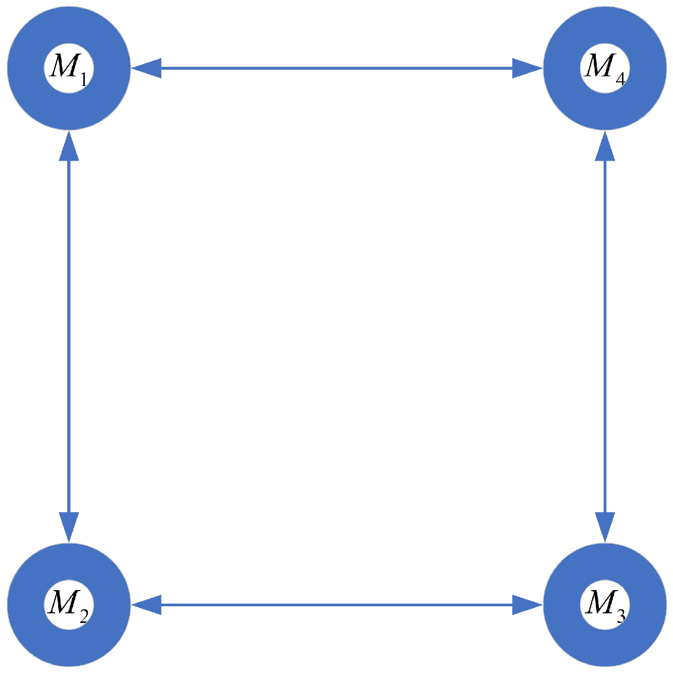
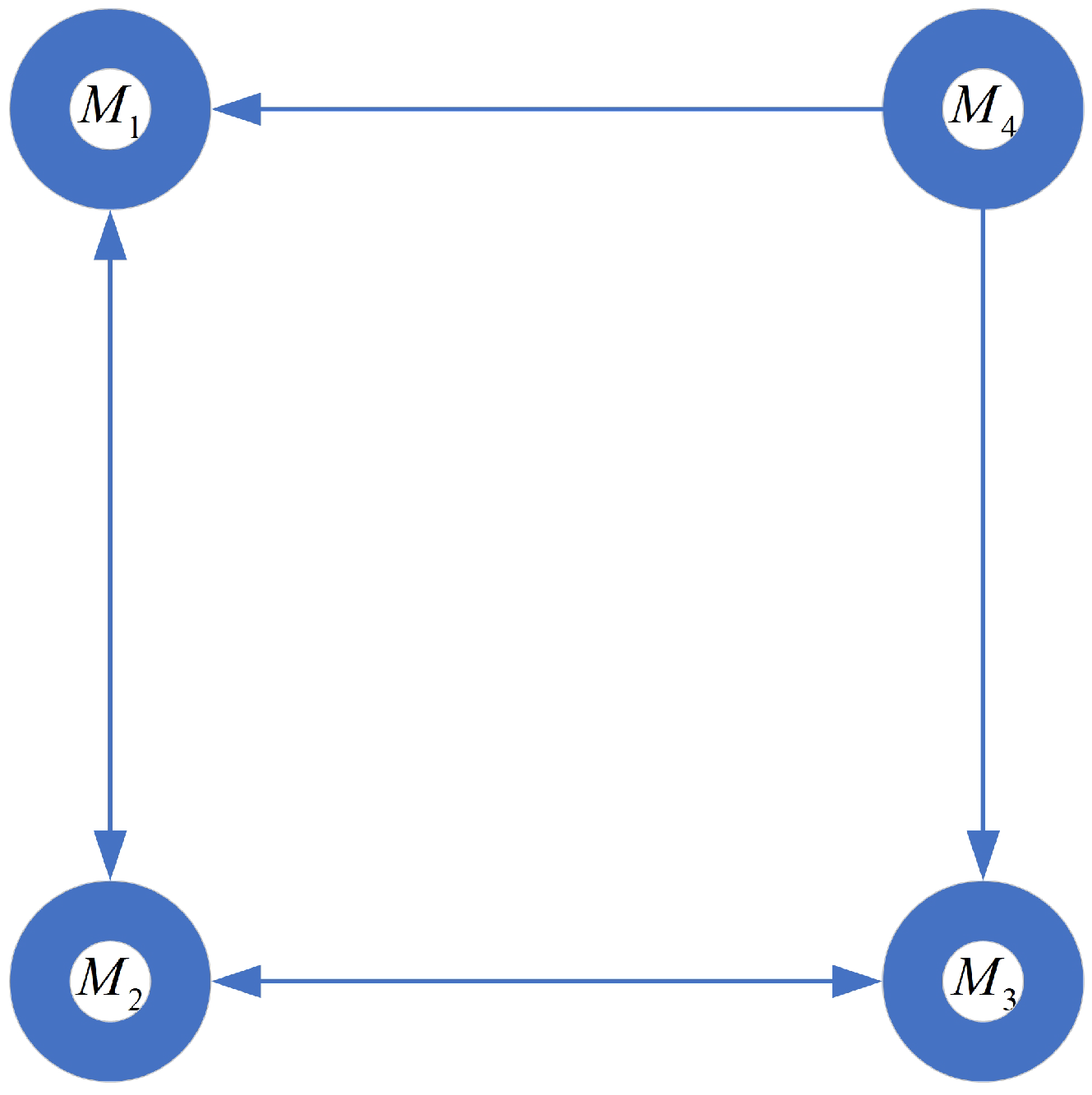
In this section, simulations demonstrate the effectiveness of the proposed predefined-time cooperative guidance law in 3D space. Considering a group of four missiles attacking a maneuvering target, the communication topology is shown in Figure 2. In addition, Figure 3 shows the communication topology when a communication failure occurs for the fourth missile. The adjacency matrices of Graph 1 and Graph 2 are shown in Equations (60) and (61), respectively. The initial conditions of the missiles and the desired impact angles are shown in Table 1. The initial position of the target is (3160, 3180, 3160) m and the three acceleration components of the target are all 20 m m s 2 s 2 . In addition, the control inputs are constrained to be u ε , i 100 m m s 2 s 2 , u η , i 100 m m s 2 s 2 , considering the limited control input capability of the missile.
A = 0 1 0 1 1 0 1 0 0 1 0 1 1 0 1 0
A ¯ = 0 1 0 0 1 0 1 0 0 1 0 0 1 0 1 0
The control parameters are chosen as follows: c = 0.25 , d = 4 , and λ 2 L G is calculated as 1.3820; the predefined settling time is T b = 10 s. m 1 = m 2 = 0.2 , n 1 = n 2 = 0.3 , μ 1 = μ 2 = 0.1 ; the predefined settling time is T c = T d = 5 s.

6.1. Simulation of Guidance Law with Impact Time and Angle Constraints

The simulation results of the simultaneous attack of four missiles against a maneuvering target are shown in Figure 4, including the range-to-go, r i , velocity along the LOS direction, V r , i , the impact angles, ε i and η i and their time derivatives, and three acceleration components: u r , i , u ε , i , and u η , i . The ranges-to-go approach zero at the predefined time of 10 s, that is, all four missiles can hit the target in 10 s. The impact angles ε i and η i and their time derivatives and three acceleration components, u r , i , u ε , i , and u η , i , can all be approached or agreed upon at 2 s. Simulation results show that the proposed predefined-time cooperative guidance law can successfully accomplish the simultaneous attack on a maneuvering target.

6.2. Simulation of Guidance Law Based on the Event-Triggered Mechanism

Firstly, the guidance law (46) along the LOS direction with the event-triggered threshold satisfied (49) and the guidance law (17) along the LOS direction without considering the event-triggered mechanism are compared, as shown in Figure 5. From the figure, it can be seen that, after the introduction of the event-triggered mechanism, the acceleration components of the four missiles along the LOS direction are reduced to different degrees, indicating that the introduction of the event-triggered mechanism can reduce the control input along the LOS direction.
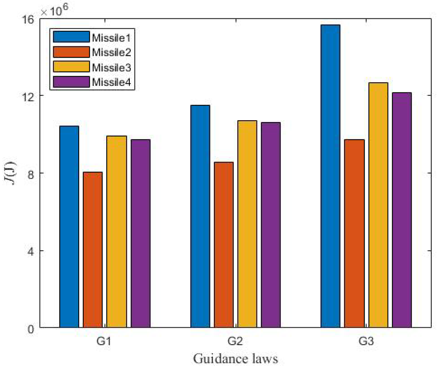
Secondly, to investigate the effect of the proposed predefined-time cooperative guidance law based on the event-triggered mechanism on the energy consumption of the missile, the following cost function is considered [44]:
J i = 1 2 x 1 , i 2 + x 3 , i 2 + x 5 , i 2 + 0 T b u r , i 2 + u ε , i 2 + u η , i 2 d t
The study then compares the energy consumption under the proposed predefined-time cooperative guidance law (G1) based on the event-triggered mechanism with the predefined-time cooperative guidance law (G2) that does not take the event-triggered mechanism into account, and the prescribed-time cooperative guidance law (G3) that introduces the PTESO [26]. In particular, the cost function of the prescribed-time cooperative guidance law with the introduction of the PTESO is
J i = 1 2 x 1 , i 2 + x 3 , i 2 + x 5 , i 2 + d ^ r , i 2 + d ^ ε , i 2 + d ^ η , i 2 + 0 T b u r , i 2 + u ε , i 2 + u η , i 2 d t
where d ^ r , i , d ^ ε , i , and d ^ η , i are the estimates of d r , i , d ε , i , and d η , i obtained through PTESO, respectively.
Figure 6 shows a comparative plot of the difference in energy consumption between the above three guidance laws under the same initial conditions. The figure shows that the energy consumption under G1 is less than G2. Although the reduction in energy consumption is less significant, it is enough to show the effectiveness of introducing the event-triggered mechanism in reducing the energy consumption of the missile. The missile energy consumption under G3, on the other hand, has a more significant increase than G1 and G2. This can also be corroborated by the fact that there are three more data items in (63) than in (62).

6.3. Simulation of Disturbance Observation

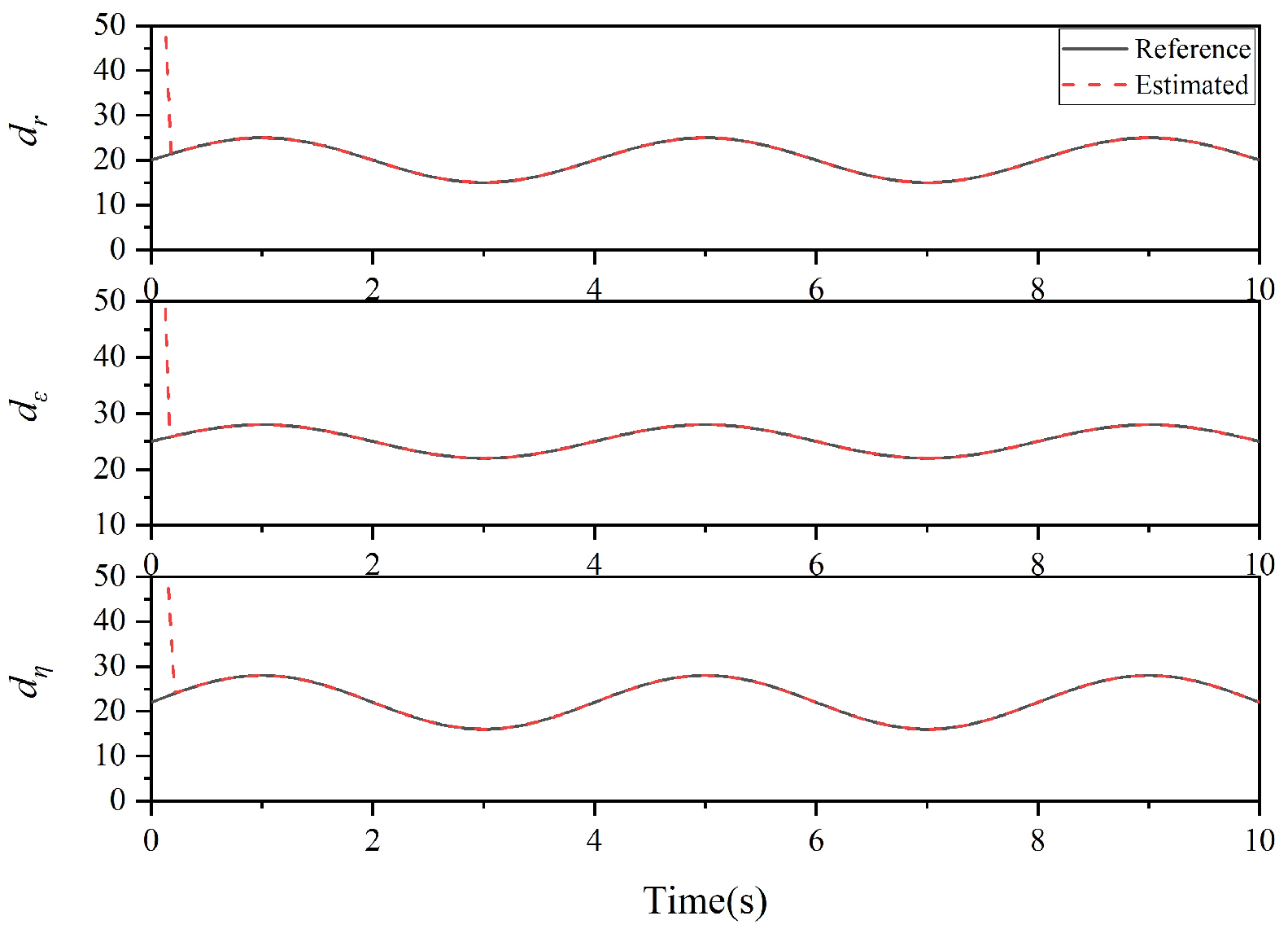
In this section, external disturbances and uncertainties are added to the 3D engagement kinematic model, and the acceleration terms of the target are considered as disturbances. The disturbances are then estimated using PTESO, as shown in Figure 7. The disturbances in the three components of the LOS system are 5 · sin π t π t 2 2 , 3 · sin π t π t 2 2 , and 6 · sin π t π t 2 2 , respectively. Figure 7 shows that the disturbances can be accurately estimated using PTESO, thus verifying the effectiveness of PTESO in the proposed guidance law.

6.4. Simulation of Guidance Law with Communication Failure and Input Time-Delay

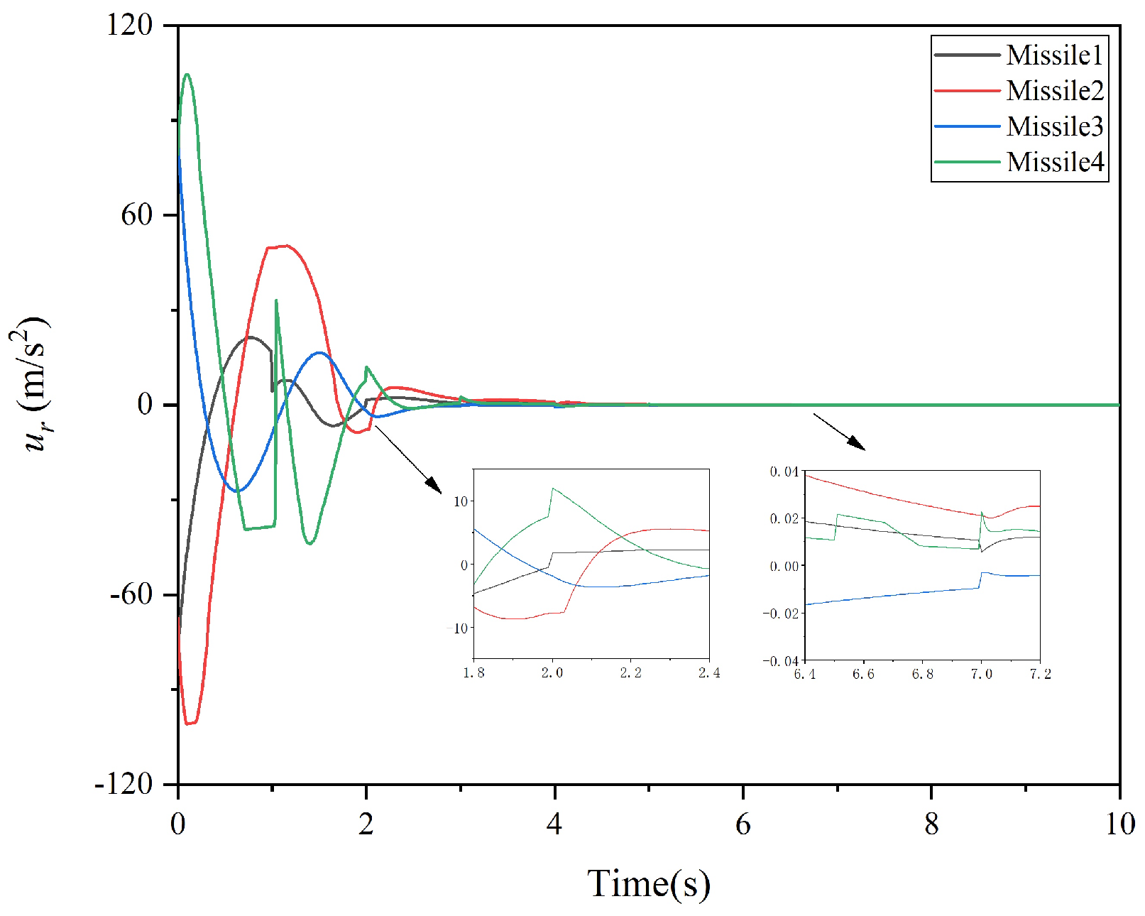
The communication topology shown in Figure 3 is compared to Figure 2, where the forth missile fails to receive information from neighbors, i.e., the first and third missiles. When 2 s t 2.2 s, the system is in the process of convergence; when 6.5 s t 6.8 s, the system is converged. In these two stages, the communication topology is switched to Figure 3. The simulation results are shown in Figure 8. Since there is no information interaction perpendicular to the LOS direction, only the control input u r , i along the LOS direction is listed. Figure 8 shows that the consistency of the multi-missile system can still be achieved regardless of whether topological transformations occur during or after convergence. A closer look reveals that when the communication topology is switched from Graph 1 to Graph 2, the forth missile is unable to receive information from the first and third missiles, i.e., a 4 j = 0 , j = 1 , , 5 . Therefore, according to the guidance law (52), u r , 4 will change, which is consistent with the simulation results.
In addition, we compare the impact times and miss distances between G1 and G3 in the case of communication time-delay. In this case, the initial parameters of the missiles, target, and guidance laws remain the same; only the communication delay time, τ m , is increased. With G1 and G3 in action, we set three control input time-delays for each missile to τ m = 0.5 s. The simulation comparison results along the LOS direction are shown in Table 2. It can be observed that the impact times of all four missiles under G1 are 10.12 s, which are very close to the predefined settling time of 10 s. In contrast, the impact times of all four missiles under G3 are as high as 11 s. It can also be seen from the miss distances that all four missiles under G1 have miss distances of about 0.3 m, while the miss distances under G3 are larger than 1 m. In summary, the superiority of the proposed predefined time cooperative guidance law based on the event-triggered mechanism is demonstrated.

7. Conclusions

Aimed at the problem of a simultaneous attack of multiple missiles against a maneuvering target in 3D space, a novel predefined-time cooperative guidance law considering the impact time and angle constraints is designed, which explicitly obtains the upper bound on the settling time of the system states. The time-to-go estimate is chosen as the consistency variable, and the communication failure and time-delay encountered during the information transmission are considered. The event-triggered mechanism is introduced into the guidance law along the LOS direction, and the event-triggered threshold is given. Then, the PTESO is used to accurately estimate disturbances. In addition, the stability of the proposed predefined-time cooperative guidance laws along and perpendicular to the LOS direction is demonstrated using Lyapunov theory. Finally, the effectiveness, robustness, and superiority of the proposed predefined-time cooperative guidance law based on the event-triggered mechanism are verified through simulations.

Author Contributions

Conceptualization, D.Z. and H.Y.; methodology, D.Z.; software, D.Z.; validation, D.Z.; data curation, D.Z.; writing—original draft preparation, D.Z.; writing—review and editing, K.D.; supervision, S.Y.; project administration, W.Y. and H.Z.; funding acquisition, H.Y. and J.G. All authors have read and agreed to the published version of the manuscript.

Funding

This research was funded by the following: (1) National Natural Science Foundation of China (Project No. 62203191); (2) National Defense Science and Technology Key Laboratory Fund (Project No. 2022JCJQLB06105); (3) Jiangsu Province Higher Education Basic Science (Natural Science) Research General Project (Project No. 22KJB590001); (4) Basic Strengthening Program Technology Field Fund (Project No. 2023JCJQJJ0357); (5) China Postdoctoral Science Foundation (Project No. 2023M731676); (6) The Jiangsu Funding Program for Excellent Postdoctoral Talent (Project No. 2023ZB007); (7) China Postdoctoral Science Foundation (Project No. 2024M754148); (8) Postdoctoral Fellowship Program (Grade B) of China Postdoctoral Science Foundation (Project No. GZB20240980).

Data Availability Statement

All data are contained within the article.

Conflicts of Interest

The authors declare no conflicts of interest.

References

  1. Song, J.; Song, S.; Xu, S. Three-dimensional cooperative guidance law for multiple missiles with finite-time convergence. Aerosp. Sci. Technol. 2017, 67, 193–205. [Google Scholar] [CrossRef]
  2. Teng, L.; Li, C.; Guo, Y.; Ma, G. Three-dimensional finite-time cooperative guidance for multiple missiles without radial velocity measurements. Chin. J. Aeronaut. 2019, 32, 1294–1304. [Google Scholar]
  3. Yang, B.; Jing, W.; Gao, C. Three-dimensional cooperative guidance law for multiple missiles with impact angle constraint. J. Syst. Eng. Electron. 2020, 31, 1286–1296. [Google Scholar]
  4. Li, W.; Wen, Q.; He, L.; Xia, Q. Three-dimensional impact angle constrained distributed cooperative guidance law for anti-ship missiles. J. Syst. Eng. Electron. 2021, 32, 447–459. [Google Scholar]
  5. Yang, X.; Song, S. Three-dimensional consensus algorithm for nonsingular distributed cooperative guidance strategy. Aerosp. Sci. Technol. 2021, 118, 106958. [Google Scholar] [CrossRef]
  6. Li, H.; Deng, Y.; Cai, Y. Three-dimensional cooperative interception guidance law with impact time constraint. Proc. Inst. Mech. Eng. Part G J. Aerosp. Eng. 2022, 236, 191–201. [Google Scholar]
  7. Zhang, W.; Du, X.; Xia, Q. A three-dimensional cooperative guidance law based on consensus theory for maneuvering targets. Math. Probl. Eng. 2019, 2019, 2120745. [Google Scholar] [CrossRef]
  8. Xu, X.; Chen, C.; Ren, Z.; Li, S. Multiple tactical missiles cooperative attack with formation-containment tracking requirement along the planned trajectory. IEEE Access 2020, 8, 87929–87946. [Google Scholar] [CrossRef]
  9. Wang, X.H.; Tan, C.P. 3-d impact angle constrained distributed cooperative guidance for maneuvering targets without angular-rate measurements. Control Eng. Pract. 2018, 78, 142–159. [Google Scholar] [CrossRef]
  10. Liu, S.; Yan, B.; Zhang, T.; Dai, P.; Liu, R.; Yan, J. Three-dimensional cooperative guidance law for intercepting hypersonic targets. Aerosp. Sci. Technol. 2022, 129, 107815. [Google Scholar] [CrossRef]
  11. Wang, X.; Lu, H.; Huang, X.; Yang, Y.; Zuo, Z. Three-dimensional time-varying sliding mode guidance law against maneuvering targets with terminal angle constraint. Chin. J. Aeronaut. 2022, 35, 303–319. [Google Scholar] [CrossRef]
  12. Liu, Z.; Lv, Y.; Zhou, J.; Hu, L. On 3d simultaneous attack against manoeuvring target with communication delays. Int. J. Adv. Robot. Syst. 2020, 17, 1729881419894808. [Google Scholar] [CrossRef]
  13. Yu, C.; Zhu, B.; Zheng, J.; Wang, W. Three dimensional cooperative guidance for intercepting a manoeuvering target. IET Control Theory Appl. 2024, 18, 530–540. [Google Scholar] [CrossRef]
  14. Chen, Z.; Chen, W.; Liu, X.; Cheng, J. Three-dimensional fixed-time robust cooperative guidance law for simultaneous attack with impact angle constraint. Aerosp. Sci. Technol. 2021, 110, 106523. [Google Scholar] [CrossRef]
  15. Yu, H.; Dai, K.; Li, H.; Zou, Y.; Ma, X.; Ma, S.; Zhang, H. Cooperative guidance law for multiple missiles simultaneous attacks with fixed-time convergence. Int. J. Control 2023, 96, 2167–2180. [Google Scholar] [CrossRef]
  16. Chen, Z.; Liu, X.; Chen, W. Three-dimensional event-triggered fixed-time cooperative guidance law against maneuvering target with the constraint of relative impact angles. J. Frankl. Inst. 2023, 360, 3914–3966. [Google Scholar] [CrossRef]
  17. Sinha, A.; Kumar, S.R.; Mukherjee, D. Three-dimensional nonlinear cooperative salvo using event-triggered strategy. J. Guid. Control Dyn. 2021, 44, 328–342. [Google Scholar] [CrossRef]
  18. Zhang, P.; Zhang, X. Multiple missiles fixed-time cooperative guidance without measuring radial velocity for maneuvering targets interception. ISA Trans. 2022, 126, 388–397. [Google Scholar] [CrossRef]
  19. Dong, W.; Wang, C.; Wang, J.; Zuo, Z.; Shan, J. Fixed-time terminal angle-constrained cooperative guidance law against maneuvering target. IEEE Trans. Aerosp. Electron. Syst. 2021, 58, 1352–1366. [Google Scholar] [CrossRef]
  20. You, H.; Chang, X.; Zhao, J.; Wang, S.; Zhang, Y. Three-dimensional impact-angle-constrained fixed-time cooperative guidance algorithm with adjustable impact time. Aerosp. Sci. Technol. 2023, 141, 108574. [Google Scholar] [CrossRef]
  21. Ma, M.-C.; Song, S.-M. Three-dimensional prescribed performance cooperative guidance law with spatial constraint for intercepting manoeuvring targets. Int. J. Control 2023, 96, 1424–1435. [Google Scholar] [CrossRef]
  22. Yu, H.; Dai, K.; Li, H.; Zou, Y.; Ma, X.; Ma, S.; Zhang, H. Three-dimensional adaptive fixed-time cooperative guidance law with impact time and angle constraints. Aerosp. Sci. Technol. 2022, 123, 107450. [Google Scholar] [CrossRef]
  23. Sánchez-Torres, J.D.; Sanchez, E.N.; Loukianov, A.G. Predefined-time stability of dynamical systems with sliding modes. In Proceedings of the 2015 American Control Conference (ACC), Chicago, IL, USA, 1–3 July 2015; pp. 5842–5846. [Google Scholar]
  24. Sinha, A.; Kumar, S.R. Cooperative target capture using predefined-time consensus over fixed and switching networks. Aerosp. Sci. Technol. 2022, 127, 107686. [Google Scholar] [CrossRef]
  25. Zhang, Y.; Tang, S.; Guo, J. Two-stage cooperative guidance strategy using a prescribed-time optimal consensus method. Aerosp. Sci. Technol. 2020, 100, 105641. [Google Scholar] [CrossRef]
  26. Cui, L.; Jin, N.; Chang, S.; Zuo, Z. Prescribed-time guidance scheme design for missile salvo attack. J. Frankl. Inst. 2022, 359, 6759–6782. [Google Scholar] [CrossRef]
  27. Wang, Z.; Fu, W.; Fang, Y.; Zhu, S.; Wu, Z.; Wang, M. Prescribed-time cooperative guidance law against maneuvering target based on leader-following strategy. ISA Trans. 2022, 129, 257–270. [Google Scholar] [CrossRef]
  28. Wang, Z.; Fu, Z.; Wu, Z.; Zhu, C.; Li, J. Three-dimensional cooperative guidance law against maneuvering target with time-varying communication delays. Int. J. Aeronaut. Space Sci. 2023, 25, 605–621. [Google Scholar] [CrossRef]
  29. Zhang, D.; Yu, H.; Dai, K.; Yi, W.; Zhang, H.; Lei, Z. Multiple-missile fixed-time integrated guidance and control design with multi-stage interconnected observers under impact angle and input saturation constraints. IET Control Theory Appl. 2024. [Google Scholar] [CrossRef]
  30. Aldana-López, R.; Gómez-Gutiérrez, D.; Jiménez-Rodríguez, E.; Sánchez-Torres, J.D.; Loukianov, A.G. On predefined-time consensus protocols for dynamic networks. J. Frankl. Inst. 2020, 357, 11880–11899. [Google Scholar] [CrossRef]
  31. Defoort, M.; Polyakov, A.; Demesure, G.; Djemai, M.; Veluvolu, K. Leader-follower fixed-time consensus for multi-agent systems with unknown nonlinear inherent dynamics. IET Control Theory Appl. 2015, 9, 2165–2170. [Google Scholar] [CrossRef]
  32. Polyakov, A. Nonlinear feedback design for fixed-time stabilization of linear control systems. IEEE Trans. Autom. Control 2011, 57, 2106–2110. [Google Scholar] [CrossRef]
  33. Sánchez-Torres, J.D.; Gómez-Gutiérrez, D.; López, E.; Loukianov, A.G. A class of predefined-time stable dynamical systems. IMA J. Math. Control. Inf. 2018, 35 (Suppl. 1), i1–i29. [Google Scholar] [CrossRef]
  34. Jiménez-Rodríguez, E.; Sánchez-Torres, J.D.; Gómez-Gutiérrez, D.; Loukianov, A.G. Predefined-time stabilization of high order systems. In Proceedings of the 2017 American Control Conference (ACC), Seattle, WA, USA, 24–26 May 2017; pp. 5836–5841. [Google Scholar]
  35. Jiménez-Rodríguez, E.; Sánchez-Torres, J.D.; Loukianov, A.G. On optimal predefined-time stabilization. Int. J. Robust Nonlinear Control 2017, 27, 3620–3642. [Google Scholar] [CrossRef]
  36. Ni, J.; Liu, L.; Tang, Y.; Liu, C. Predefined-time consensus tracking of second-order multiagent systems. IEEE Trans. Syst. Man Cybern. Syst. 2019, 51, 2550–2560. [Google Scholar] [CrossRef]
  37. Olver, F.W. NIST Handbook of Mathematical Functions Hardback and CD-ROM; Cambridge University Press: Cambridge, UK, 2010. [Google Scholar]
  38. Zhou, J.; Yang, J. Distributed guidance law design for cooperative simultaneous attacks with multiple missiles. J. Guid. Control. Dyn. 2016, 39, 2439–2447. [Google Scholar] [CrossRef]
  39. Aragues, R.; Shi, G.; Dimarogonas, D.V.; Sagüés, C.; Johansson, K.H.; Mezouar, Y. Distributed algebraic connectivity estimation for undirected graphs with upper and lower bounds. Automatica 2014, 50, 3253–3259. [Google Scholar] [CrossRef]
  40. Zhou, J.; Lü, Y.; Li, Z.; Yang, J. Cooperative guidance law design for simultaneous attack with multiple missiles against a maneuvering target. J. Syst. Sci. Complex. 2018, 31, 287–301. [Google Scholar] [CrossRef]
  41. Zhang, P.; Liu, H.H.; Li, X.; Yao, Y. Fault tolerance of cooperative interception using multiple flight vehicles. J. Frankl. Inst. 2013, 350, 2373–2395. [Google Scholar] [CrossRef]
  42. Cucuzzella, M.; Incremona, G.P.; Ferrara, A. Event-triggered variable structure control. Int. J. Control 2020, 93, 252–260. [Google Scholar] [CrossRef]
  43. Sinha, A.; Mishra, R.K. Consensus in first order nonlinear heterogeneous multi-agent systems with event-based sliding mode control. Int. J. Control 2020, 93, 858–871. [Google Scholar] [CrossRef]
  44. Balhance, N.; Weiss, M.; Shima, T. Cooperative guidance law for intrasalvo tracking. J. Guid. Control Dyn. 2017, 40, 1441–1456. [Google Scholar] [CrossRef]
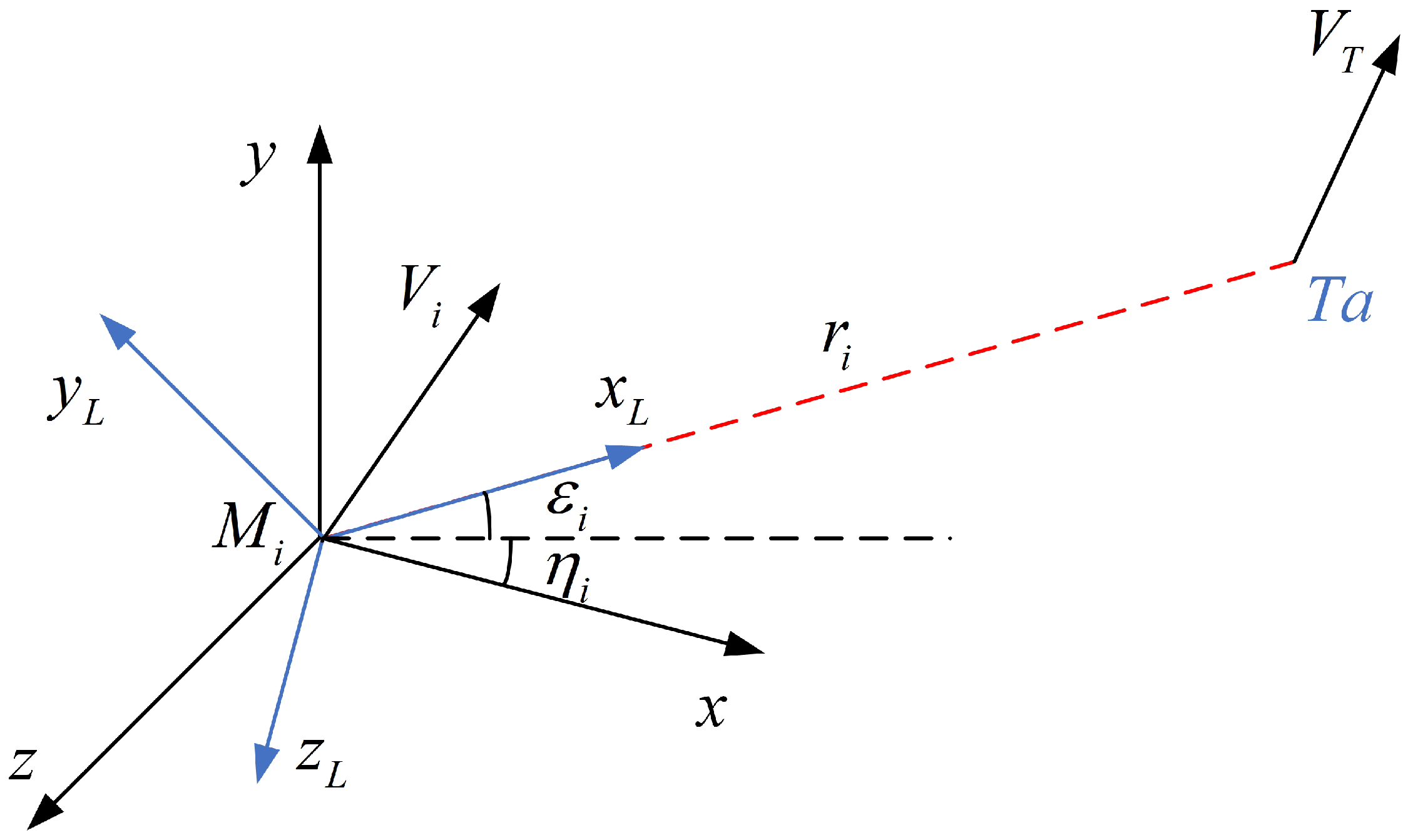
Figure 1. 3D engagement geometry of the missile–target.
Aerospace 11 00999 g001
Figure 2. Communication topology (Graph 1).
Aerospace 11 00999 g002
Figure 3. Topology under communication failure (Graph 2).
Aerospace 11 00999 g003
Figure 4. Simulation results of the predefined-time cooperative guidance law. (a) Trajectories in ( X , Y , Z ) space. (b) The ranges-to-go of missiles. (c) The relative velocity component along the LOS direction. (d) The elevation LOS angle. (e) The azimuth LOS angle. (f) Elevation LOS angular rate. (g) Azimuth LOS angular rate. (h) The acceleration component along the LOS direction. (i) The acceleration component perpendicular to the LOS direction in the longitudinal plane. (j) The acceleration component perpendicular to the LOS direction in the lateral plane.
Aerospace 11 00999 g004aAerospace 11 00999 g004bAerospace 11 00999 g004c
Figure 5. The acceleration component along the LOS direction based on the event-triggered mechanism.
Aerospace 11 00999 g005
Figure 6. Bar graph of energy consumption in different guidance laws.
Aerospace 11 00999 g006
Figure 7. Estimation results for the disturbance observer.
Aerospace 11 00999 g007
Figure 8. Simulation results of the acceleration component along the LOS direction with communication failure.
Aerospace 11 00999 g008
Table 1. Initial states and desired impact angles of missiles.
MissilePosition (m,m,m) V r 0 (m/s) ε 0 (deg) η 0 (deg) ε f (deg) η f (deg)
M 1 (3300, −680, 3500)−50080−60−1555
M 2 (1680, −240, 1660)−50060703045
M 3 (940, −370, 1800)−50070602030
M 4 (−1660, 3000, 1260)−50050306020
Table 2. Impact times and miss distances after time-delay with different guidance laws.
Missiles in G1 and G3Impact Time (s)Miss Distance (m)
Missile1-G110.120.300
Missile1-G310.981.692
Missile2-G110.120.245
Missile2-G310.951.579
Missile3-G110.120.273
Missile3-G311.062.016
Missile4-G110.120.328
Missile4-G310.991.035
Disclaimer/Publisher’s Note: The statements, opinions and data contained in all publications are solely those of the individual author(s) and contributor(s) and not of MDPI and/or the editor(s). MDPI and/or the editor(s) disclaim responsibility for any injury to people or property resulting from any ideas, methods, instructions or products referred to in the content.