
Performance Evaluation of Ammonium Dinitramide-Based Monopropellant in a 1N Thruster

Abstract
:1. Introduction
2. Materials and Methods
2.1. ADN-Based Monopropellant
2.2. Thermal and Catalyst Bed Materials
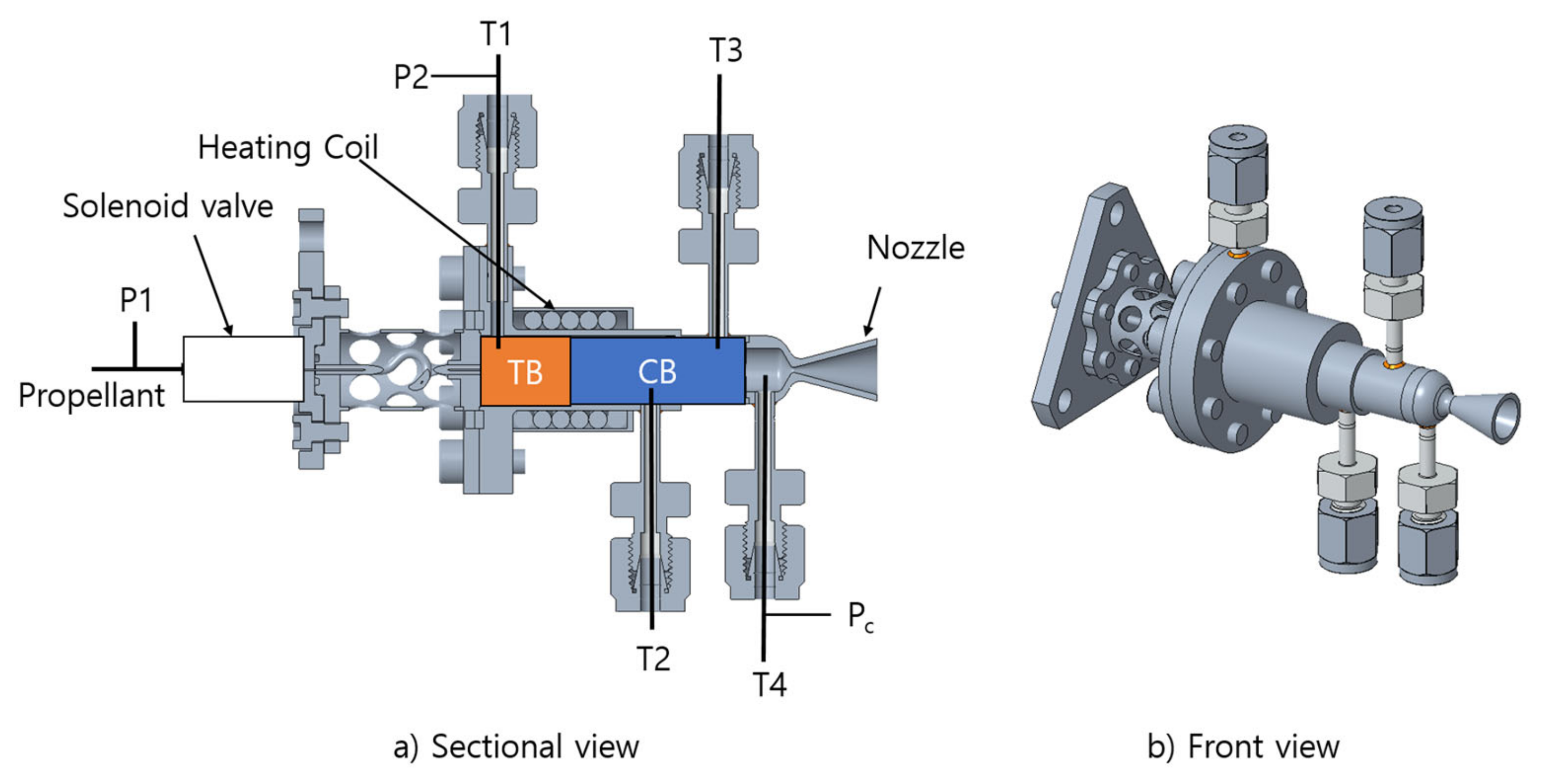
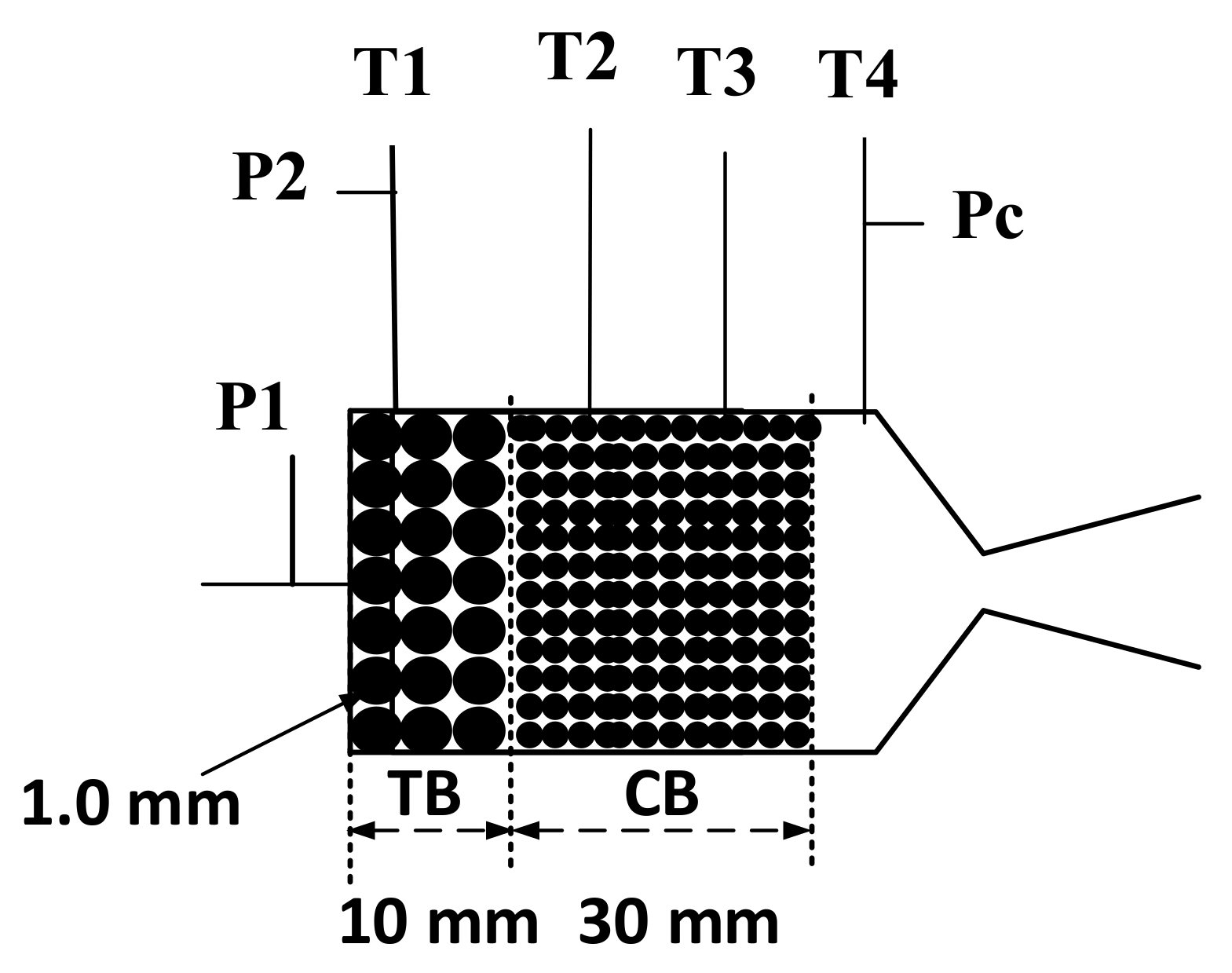
2.3. Reactor Design
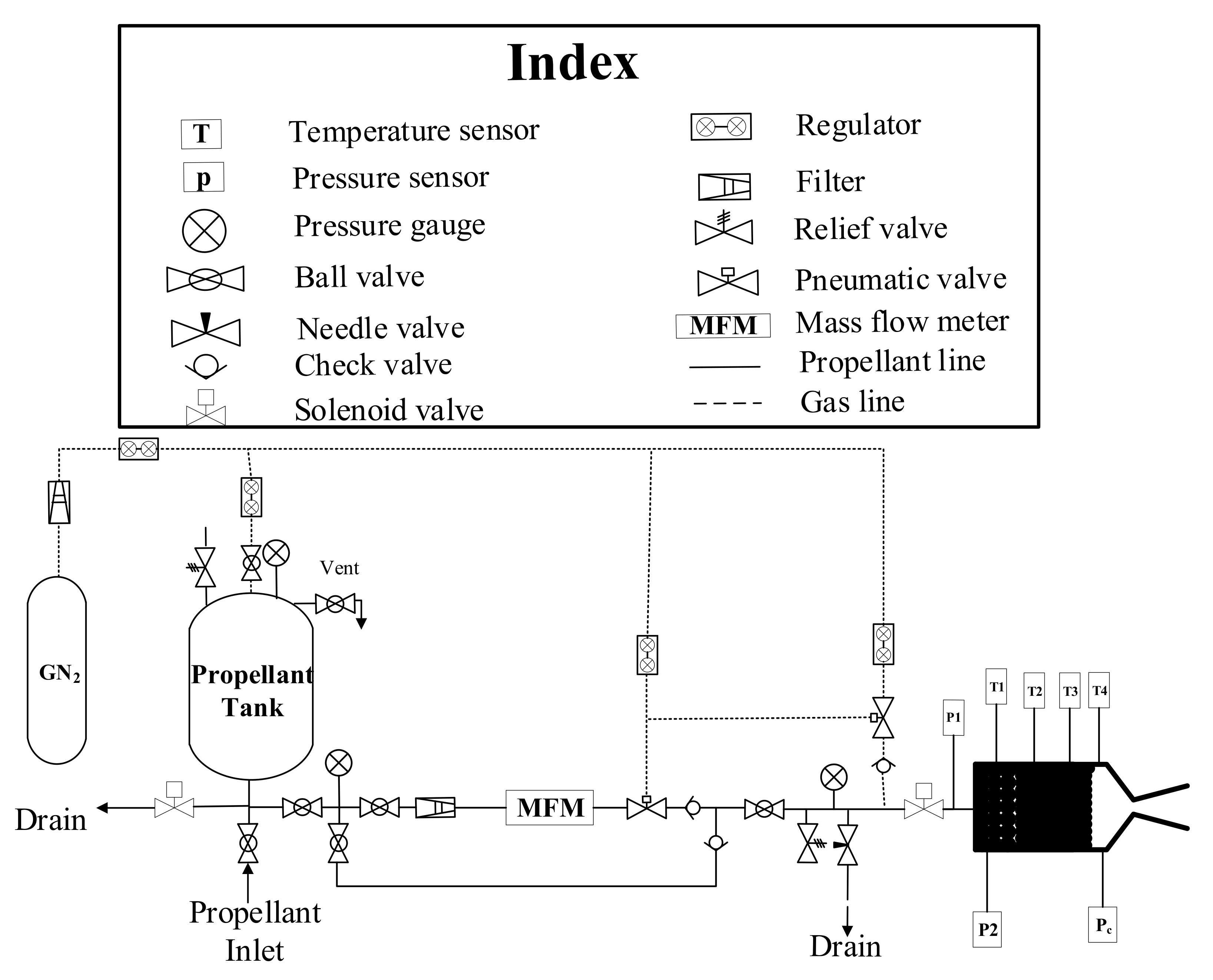
2.4. Experimental Setup
2.5. Combustion Efficiency
2.6. Combustion Instability
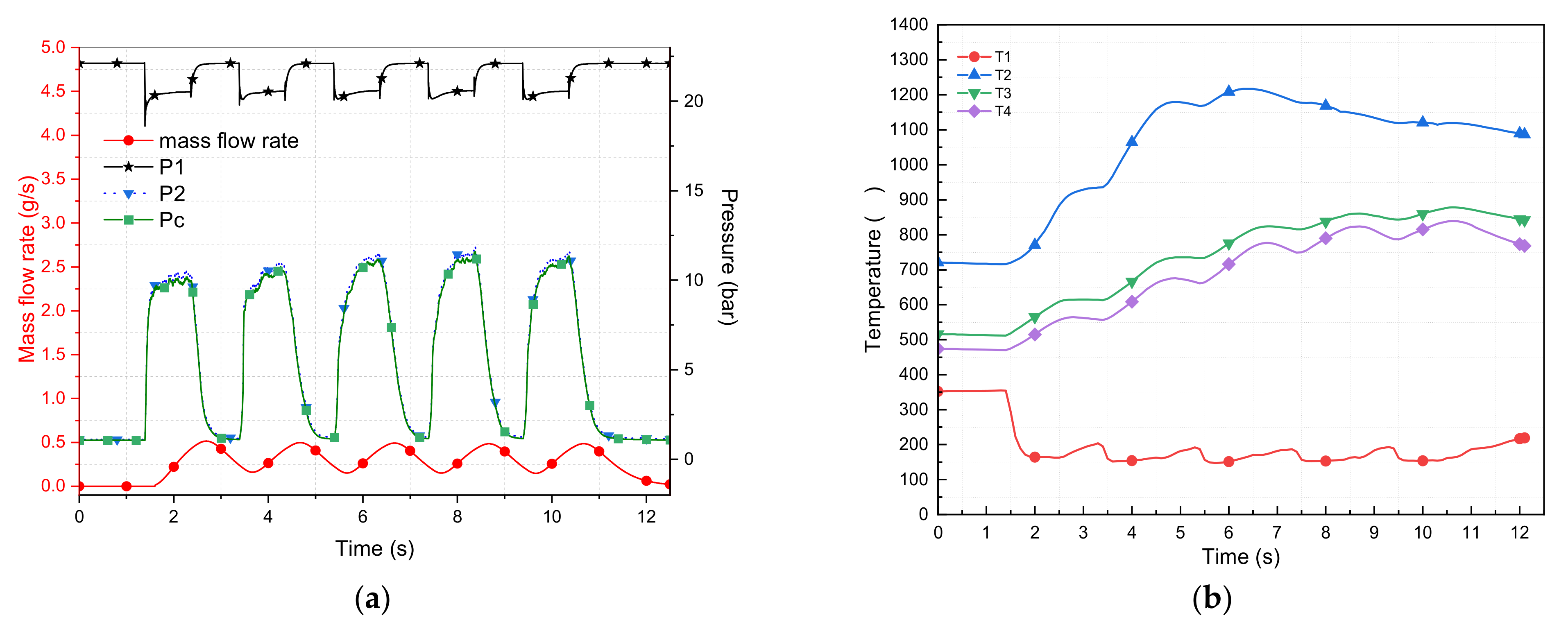
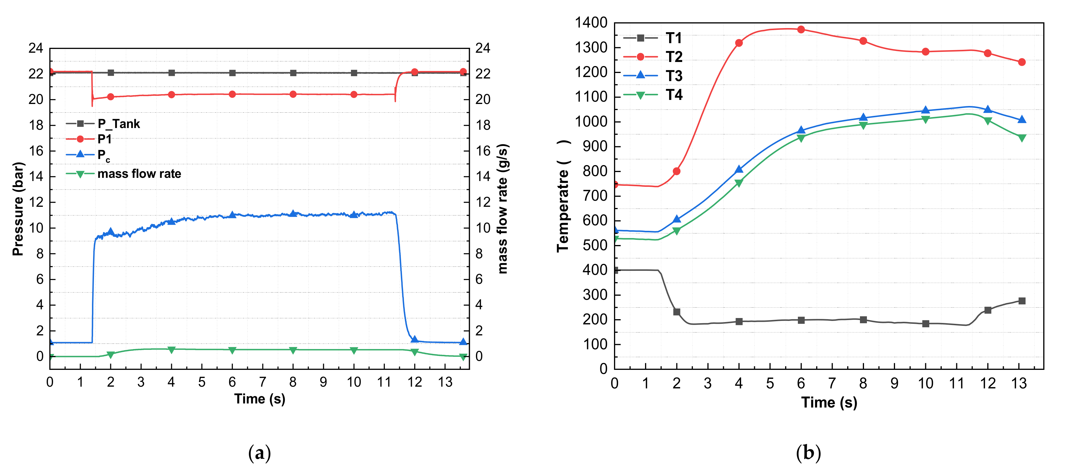
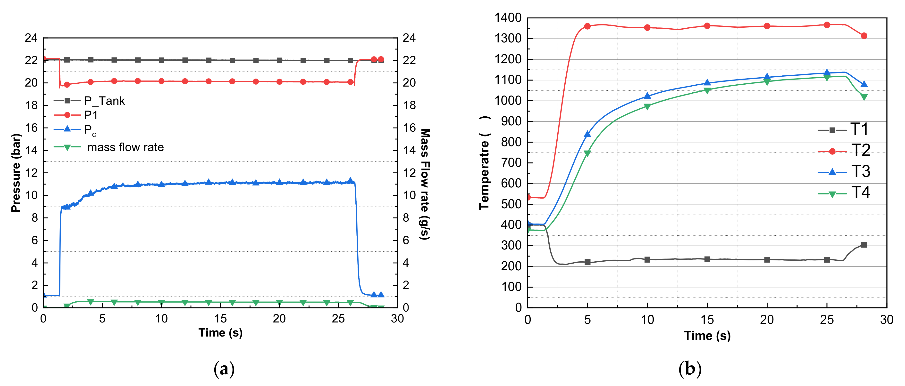
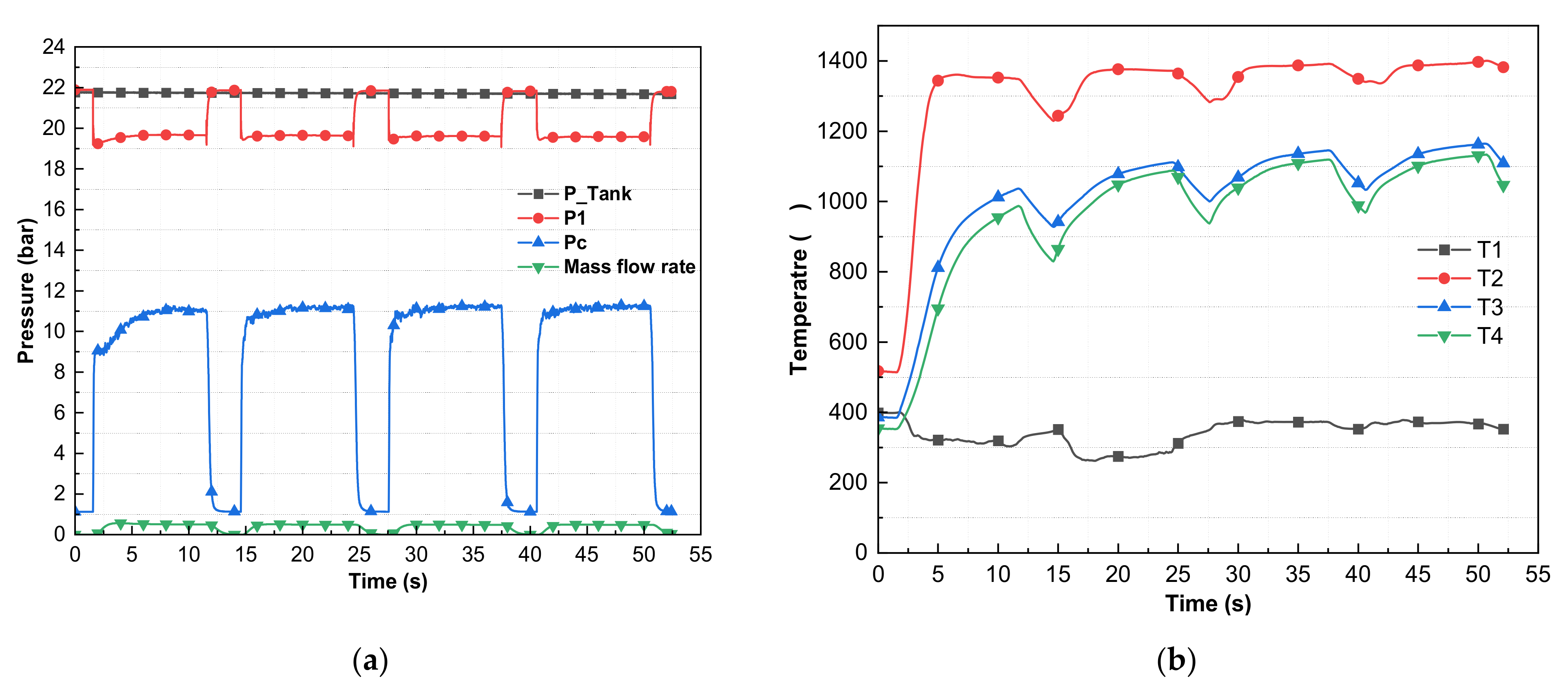
3. Results and Discussion
4. Conclusions
Author Contributions
Funding
Data Availability Statement
Conflicts of Interest
References
- Persson, M.; Anflo, K.; Friedhoff, P. Flight Heritage of Ammonium Dinitramide (ADN) Based High Performance Green Propulsion (HPGP) Systems. Propellants Explos. Pyrotech. 2019, 44, 1073–1079. [Google Scholar] [CrossRef]
- Anflo, K.; Crowe, B. In-Space Demonstration of High Performance Propulsion and Its Impact on Small Satellites. In Proceedings of the 25th Annual AIAA/USU Conference on Small Satellites, Logan, UT, USA, 8–11 August 2011; pp. 1–7. [Google Scholar]
- Dinardi, A.; Anflo, K.; Friedhoff, P. On-Orbit Commissioning of High Performance Green Propulsion (HPGP) in the SkySat Constellation. In Proceedings of the 31st Annual AIAA/USU Conference on Small Satellites, Logan, UT, USA, 4–10 August 2017. [Google Scholar]
- Karaliunaite, V. A Successful In-Orbit Test of the First Ever Chemical Propulsion System Running On-Board a CubeSat Was Performed. Available online: https://nanoavionics.com/news/successful-orbit-test-first-ever-chemical-propulsion-system-running-board-cubesat-performed/ (accessed on 10 November 2023).
- Wokes, S.; Forshaw, J.; Auburn, J. ELSA-d: Mission Design and Performance to Date; Astroscale: Oxfordshire, UK, 2021. [Google Scholar]
- Persson, M.; Anflo, K.; Dinardi, A.; Bahu, J.M. A Family of Thrusters for ADN-Based Monopropellant LMP-103S. In Proceedings of the 48th AIAA/ASME/SAE/ASEE Joint Propulsion Conference & Exhibit, Atlanta, GA, USA, 30 July–1 August 2012; pp. 1–15. [Google Scholar] [CrossRef]
- Maleix, C.; Chabernaud, P.; Brahmi, R.; Beauchet, R.; Batonneau, Y.; Kappenstein, C.; Schwentenwein, M.; Koopmans, R.J.; Schuh, S.; Scharlemann, C. Development of Catalytic Materials for Decomposition of ADN-Based Monopropellants. Acta Astronaut. 2019, 158, 407–415. [Google Scholar] [CrossRef]
- Yu, Y.S.; Li, G.X.; Zhang, T.; Chen, J.; Wang, M. Effects of Catalyst-Bed’s Structure Parameters on Decomposition and Combustion Characteristics of an Ammonium Dinitramide (ADN)-Based Thruster. Energy Convers. Manag. 2015, 106, 566–575. [Google Scholar] [CrossRef]
- Hong, S.; Heo, S.; Kim, W.; Jo, Y.M.; Park, Y.-K.; Jeon, J.-K. Catalytic Decomposition of of an Energetic Ionic Liquids Solutions over Hexaaluminate Catalysts. Catalysts 2019, 9, 80. [Google Scholar] [CrossRef]
- Bhosale, V.K.; Yoon, W.; Yoon, H. Enhancing the Catalytic Performance of Platinum-Doped Lanthanum Hexaaluminate through Reduction Method Variation. Catalysts 2023, 13, 1413. [Google Scholar] [CrossRef]
- Remissa, I.; Jabri, H.; Hairch, Y.; Toshtay, K.; Atamanov, M.; Azat, S.; Amrousse, R. Propulsion Systems, Propellants, Green Propulsion Subsystems and Their Applications: A Review. Eurasian Chem. J. 2023, 25, 3–19. [Google Scholar] [CrossRef]
- Yoon, W.; Bhosale, V.K.; Yoon, H. Reactor Structure for the Decomposition of ADN-Based Monopropellant. Aerospace 2023, 10, 686. [Google Scholar] [CrossRef]
- Harimech, Z.; Toshtay, K.; Atamanov, M.; Azat, S.; Amrousse, R. Thermal Decomposition of Ammonium Dinitramide (ADN) as Green Energy Source for Space Propulsion. Aerospace 2023, 10, 832. [Google Scholar] [CrossRef]
- Nosseir, A.E.S.; Cervone, A.; Pasini, A. Review of State-of-the-Art Green Monopropellants: For Propulsion Systems Analysts and Designers. Aerospace 2021, 8, 20. [Google Scholar] [CrossRef]
- Negri, M.; Wilhelm, M.; Hendrich, C.; Wingborg, N.; Gediminas, L.; Adelöw, L.; Maleix, C.; Chabernaud, P.; Brahmi, R.; Beauchet, R.; et al. New Technologies for Ammonium Dinitramide Based Monopropellant Thrusters—The Project RHEFORM. Acta Astronaut. 2018, 143, 105–117. [Google Scholar] [CrossRef]
- Negri, M. Replacement of Hydrazine: Overview and First Results of the H2020 Project Rheform. In Proceedings of the 6th European Conference for Aeronautics and Space Sciendes (EUCASS), Krakau, Poland, 29 June–3 July 2015; pp. 1–12. [Google Scholar]
- Rocketdyne, A. GPIM AF-M315E Propulsion System. In Proceedings of the 51st AIAA/SAE/ASEE Joint Propulsion Conference, Orlando, FL, USA, 27–29 July 2015; pp. 1–12. [Google Scholar]
- Yao, Z.; Zhang, W.; Meng, W.; Jun, C.; Yan, S. Experimental Investigation and On-Orbit Flying Validation of an ADN-Based Liquid Space Engine. J. Rocket Propuls. 2018, 44, 8–14. [Google Scholar]
- Oh, S.; Kang, S.; Oh, D. Hydrogen Peroxide Monopropellant Thruster for KSLV-II Reaction Control System. J. Korean Soc. Aeronaut. Space Sci. 2019, 47, 335–343. [Google Scholar] [CrossRef]
- Mcbride, B.J.; Gordon, S. Computer Program for Calculation of Complex Chemical Equilibrium Composition and Applications II. User Manual and Pogram Description. In NASA Reference Publication 1311; NASA Lewis Research Center Cleveland: Cleveland, OH, USA, 1996. [Google Scholar]
- Gordon, S.; McBride, B.J. Computer Program for Calculation Complex Chemical Equilibrium Compositions and Applications I. Analysis; NASA Lewis Research Center Cleveland: Cleveland, OH, USA, 1994; ISBN 1995001376. [Google Scholar]
- ECAPS; HPGP. Thrusters. Available online: https://www.ecaps.se/rocket-engines (accessed on 22 November 2023).
- Chen, J.; Li, G.; Zhang, T.; Wang, M.; Yu, Y. Experimental Investigation of the Catalytic Decomposition and Combustion Characteristics of a Non-Toxic Ammonium Dinitramide (ADN)-Based Monopropellant Thruster. Acta Astronaut. 2016, 129, 367–373. [Google Scholar] [CrossRef]


| Chemicals | Composition (wt%) |
|---|---|
| ADN | 63.0 |
| CH3OH | 18.4 |
| NH3 | 4.6 |
| H2O | 14.0 |
| Parameters | Value |
|---|---|
| Chamber pressure (Pc, bar) | 11 bar |
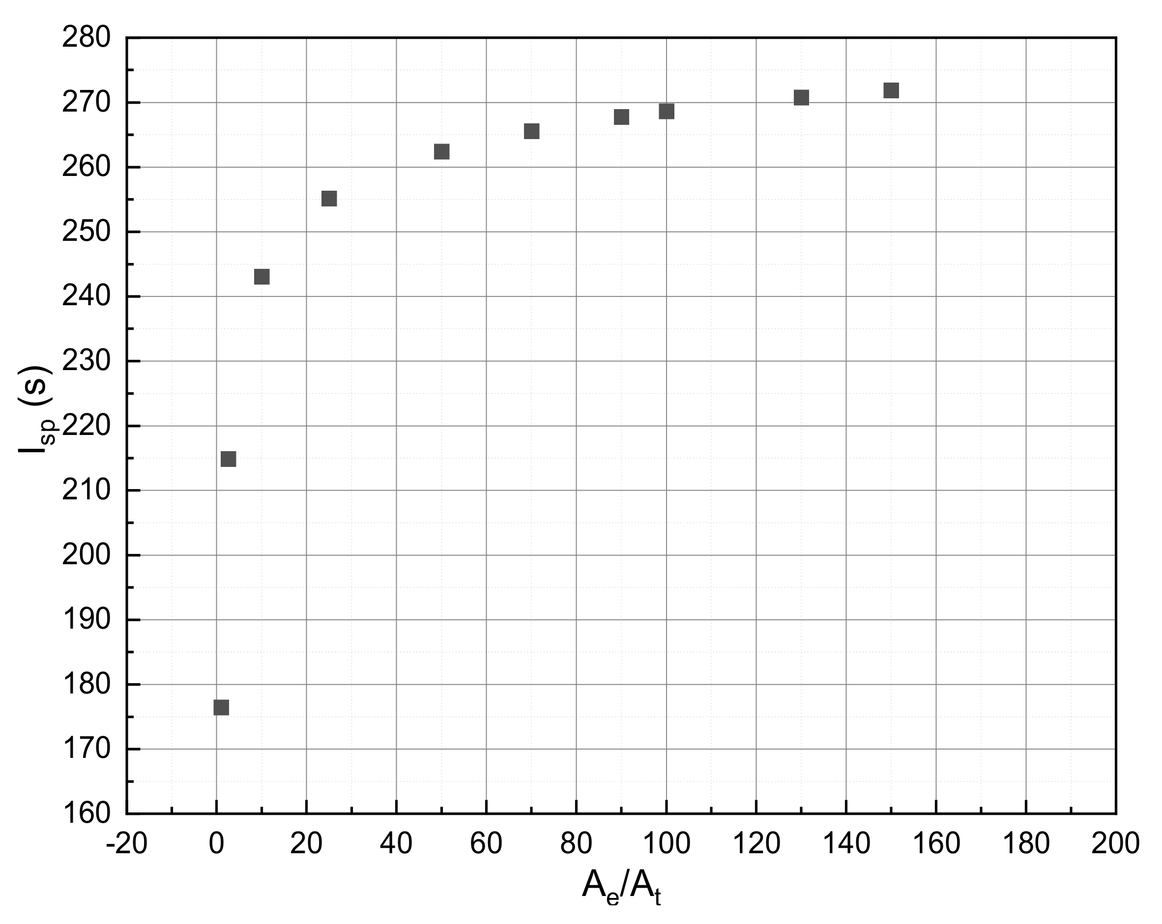
| Nozzle expansion ratio (Ae/At) | 100 |
| Heat of formation of ADN in monopropellant (kJ/mol) | −110.22 kJ/mol |
| Characteristic velocity (c*, m/s) | 1389.7 m/s |
| Ideal specific impulse (Isp, s) | 268.6 s |
| Ideal reaction temperature (T) | 1957 K (1683 °C) |
| Parameters | 100 mN | 0.5 N | 1N | 5 N | 22 N | 50 N |
|---|---|---|---|---|---|---|
| Theoretical Isp (s, CEA) | 268 (Ae/At: 100) | 270 (Ae/At: 150) | ||||
| Suggested Isp (s, ECAPS) | 209 | 219 | 231 | 253 | 255 | 255 |
| Estimated Isp efficiency (%) | 78 | 82 | 86 | 94 | 94 | 94 |
| Parameters | Value |
|---|---|
| Thrust (N) | 1 |
| Chamber pressure (bar) | 11 |
| Nozzle expansion ratio | 100 |
| Nozzle throat diameter (mm) | 0.84 |
| Reactor diameter (mm) | 10 |
| Reactor length (mm) | 40 |
| Injector orifice diameter (mm) | 0.25 |
| Number of injector orifice | 1 |
| Estimated Isp efficiency (%) | 86 |
| Target mass flow rate (g/s) | 0.447 |
| Test | Number of Consecutive Pulses | Time, (s) | Duty Ratio (%) | Mass Flow Rate (g/s) | Temperature (°C) | Temperature during Combustion (T) (°C) | Pressure during Combustion, PMax (bar) | ΔP, (bar) | # ղc* (%) | |||||
|---|---|---|---|---|---|---|---|---|---|---|---|---|---|---|
| $ T1 | T1Min | T2Max | T3Max | T4Max | P1 | P2 | * Pc | |||||||
| 1 | 5 | 1 | 49 | 1.097 | 354 | 120 | 700 | 350 | 412 | 20.24 | 9.06 | 8.70 | 11.18 | 32 |
| 1 | 0.77 | 132 | 865 | 570 | 519 | 20.44 | 10.03 | 9.80 | 10.41 | 51 | ||||
| 1 | 0.67 | 128 | 808 | 639 | 603 | 20.58 | 11.31 | 11.00 | 9.27 | 66 | ||||
| 1 | 0.57 | 123 | 874 | 687 | 642 | 20.62 | 11.34 | 11.00 | 9.28 | 78 | ||||
| 1 | 0.54 | 121 | 933 | 731 | 681 | 20.62 | 11.58 | 11.29 | 9.04 | 85 | ||||
| 2 | 5 | 1 | 49 | 0.55 | 351 | 175 | 839 | 497 | 436 | 20.46 | 10.23 | 9.90 | 10.23 | 73 |
| 1 | 0.51 | 143 | 1127 | 658 | 585 | 20.58 | 11.10 | 10.70 | 9.48 | 85 | ||||
| 1 | 0.5 | 135 | 1128 | 754 | 700 | 20.60 | 11.58 | 11.27 | 9.02 | 91 | ||||
| 1 | 0.49 | 123 | 1075 | 791 | 749 | 20.60 | 11.84 | 11.61 | 8.76 | 96 | ||||
| 1 | 0.49 | 128 | 1071 | 817 | 775 | 20.60 | 11.71 | 11.41 | 8.89 | 94 | ||||
| 3 | 5 | 1 | 49 | 0.51 | 353 | 164 | 925 | 615 | 564 | 20.50 | 10.48 | 10.18 | 10.02 | 81 |
| 1 | 0.5 | 153 | 1180 | 735 | 675 | 20.53 | 11.08 | 10.75 | 9.45 | 87 | ||||
| 1 | 0.49 | 147 | 1270 | 824 | 776 | 20.55 | 11.48 | 11.16 | 9.07 | 92 | ||||
| 1 | 0.48 | 152 | 1146 | 860 | 823 | 20.56 | 11.90 | 11.60 | 8.66 | 98 | ||||
| 1 | 0.48 | 153 | 1119 | 878 | 839 | 20.54 | 11.64 | 11.35 | 8.9 | 96 | ||||
| Tests | Consecutive Pulses | Pulse Time (s) | Duty Ratio (%) | Mass Flow Rate g/s | Preheating Temperature (°C) | Temperature during Combustion (°C) | Average Pressure (bar) | ΔP (bar) | ղc* (%) | |||||
|---|---|---|---|---|---|---|---|---|---|---|---|---|---|---|
| T1 | T1Min | T2Max | T3Max | T4Max | P1 | P2 | Pc | |||||||
| 4 | 3 | 5 | 50 | 0.55 | 383 | 241 | 1292 | 893 | 868 | 20.60 | 11.62 | 11.26 | 8.98 | 83 |
| 5 | 0.55 | 183 | 1239 | 977 | 948 | 20.56 | 11.53 | 11.21 | 9.03 | 82 | ||||
| 5 | 0.55 | 165 | 1304 | 1021 | 1001 | 20.50 | 11.36 | 11.06 | 9.14 | 81 | ||||
| 5 | 3 | 5 | 50 | 0.56 | 394 | 179 | 1346 | 921 | 897 | 20.49 | 11.27 | 10.97 | 9.22 | 79 |
| 5 | 0.54 | 171 | 1323 | 1009 | 986 | 20.47 | 11.33 | 11.04 | 9.14 | 83 | ||||
| 5 | 0.54 | 179 | 1339 | 1050 | 1032 | 20.44 | 11.36 | 11.07 | 9.08 | 83 | ||||
| 6 | 1 | 10 | 0.53 | 400 | 193 | 1376 | 1061 | 1031 | 20.40 | 11.42 | 11.12 | 8.98 | 85 | |
| 7 | 2 | 10 | 50 | 0.52 | 405 | 174 | 1400 | 1079 | 1053 | 20.40 | 11.59 | 11.26 | 8.81 | 88 |
| 10 | 0.52 | 212 | 1393 | 1122 | 1103 | 20.36 | 11.47 | 11.13 | 8.89 | 87 | ||||
| 8 | 1 | 15 | 0.52 | 398 | 180 | 1355 | 1091 | 1061 | 20.32 | 11.53 | 11.19 | 8.79 | 87 | |
| 9 | 1 | 20 | 0.51 | 400 | 197 | 1422 | 1146 | 1123 | 19.98 | 11.48 | 11.16 | 8.50 | 88 | |
| 10 | 1 | 25 | 0.51 | 400 | 210 | 1368 | 1138 | 1118 | 20.10 | 11.51 | 11.12 | 8.59 | 88 | |
| 11 | 2 | 10 | 77 | 0.51 | 400 | 151 | 1370 | 1053 | 1006 | 20.05 | 11.39 | 11.06 | 8.66 | 88 |
| 10 | 0.51 | 199 | 1375 | 1122 | 1097 | 20.01 | 11.51 | 11.09 | 8.50 | 88 | ||||
| 12 | 2 | 10 | 77 | 0.51 | 400 | 191 | 1375 | 1049 | 1005 | 19.97 | 11.41 | 11.09 | 8.56 | 88 |
| 10 | 0.51 | 334 | 1377 | 1115 | 1094 | 19.94 | 11.52 | 11.22 | 8.42 | 89 | ||||
| 13 | 2 | 10 | 77 | 0.52 | 370 | 177 | 1348 | 1021 | 964 | 19.90 | 11.32 | 11.00 | 8.58 | 86 |
| 10 | 0.51 | 251 | 1374 | 1101 | 1079 | 19.87 | 11.50 | 11.21 | 8.37 | 89 | ||||
| 14 | 2 | 10 | 77 | 0.51 | 400 | 206 | 1401 | 1058 | 1007 | 19.86 | 11.59 | 11.21 | 8.27 | 89 |
| 10 | 0.50 | 355 | 1375 | 1133 | 1107 | 19.84 | 11.61 | 11.26 | 8.23 | 91 | ||||
| 15 | 3 | 10 | 77 | 0.51 | 400 | 191 | 1362 | 1037 | 988 | 19.77 | 11.42 | 11.04 | 8.35 | 88 |
| 10 | 0.50 | 305 | 1370 | 1109 | 1089 | 19.74 | 11.57 | 11.22 | 8.17 | 91 | ||||
| 10 | 0.50 | 230 | 1395 | 1143 | 1120 | 19.70 | 11.56 | 11.22 | 8.14 | 91 | ||||
| 16 | 4 | 10 | 77 | 0.51 | 400 | 303 | 1360 | 1036 | 986 | 19.67 | 11.46 | 11.08 | 8.21 | 88 |
| 10 | 0.50 | 263 | 1376 | 1111 | 1087 | 19.65 | 11.51 | 11.21 | 8.14 | 91 | ||||
| 10 | 0.50 | 372 | 1385 | 1145 | 1118 | 19.61 | 11.6 | 11.23 | 8.01 | 91 | ||||
| 10 | 0.50 | 355 | 1391 | 1164 | 1133 | 19.57 | 11.59 | 11.24 | 7.98 | 91 | ||||
Disclaimer/Publisher’s Note: The statements, opinions and data contained in all publications are solely those of the individual author(s) and contributor(s) and not of MDPI and/or the editor(s). MDPI and/or the editor(s) disclaim responsibility for any injury to people or property resulting from any ideas, methods, instructions or products referred to in the content. |
© 2024 by the authors. Licensee MDPI, Basel, Switzerland. This article is an open access article distributed under the terms and conditions of the Creative Commons Attribution (CC BY) license (https://creativecommons.org/licenses/by/4.0/).
Share and Cite
Yoon, W.; Bhosale, V.K.; Yoon, H. Performance Evaluation of Ammonium Dinitramide-Based Monopropellant in a 1N Thruster. Aerospace 2024, 11, 110. https://doi.org/10.3390/aerospace11020110
Yoon W, Bhosale VK, Yoon H. Performance Evaluation of Ammonium Dinitramide-Based Monopropellant in a 1N Thruster. Aerospace. 2024; 11(2):110. https://doi.org/10.3390/aerospace11020110
Chicago/Turabian StyleYoon, Wonjae, Vikas Khandu Bhosale, and Hosung Yoon. 2024. "Performance Evaluation of Ammonium Dinitramide-Based Monopropellant in a 1N Thruster" Aerospace 11, no. 2: 110. https://doi.org/10.3390/aerospace11020110