Abstract
Unmanned aerial vehicles (UAVs) have already proven valuable for intelligence, search, and reconnaissance missions; however, their integration into manned aircraft to augment existing capabilities is still an emerging field. This paper describes the design of an aircraft that fits inside a G-sized sonobuoy canister, deploys from a manned aircraft in-flight, and flies for up to 111 km and 83 min while providing telemetry to a remote operator. While UAVs with similar performance requirements exist, most were designed to fit in larger canisters. Multiple UAVs can be deployed in the air to expand the search capabilities of manned aircraft, ultimately allowing a larger search area per cost compared to manned aircraft alone. Individual performance characteristics of the aircraft such as aerodynamics, weight, propulsion, and stability were developed in the preliminary design phase based on given performance requirements. The performance of the aircraft was assessed using analytical and empirical methods. Wing folding mechanisms were prototyped for use on the production aircraft for flight testing. Propulsion, aerodynamic, and structural capabilities were validated separately using experimental methods. The folding mechanisms used in this UAV allow it to achieve the benefits of a longer wingspan while remaining compact and easy to deploy.
1. Introduction
Unmanned aerial vehicles (UAVs) are an established field that expands current aerial capabilities in intelligence, surveillance, and reconnaissance (ISR) missions. UAVs provide a way to extend missions through lower operating costs than manned aircraft and the ability to keep human operators safe [1]. Historically, these UAVs have been standalone platforms, with mission profiles like those of manned aircraft. However, recent efforts have sought to integrate UAVs with manned aircraft, human-deployable launch systems, and ground-based launch systems. Early development was inspired by the 2004 Navy Sonobuoy Tube-Launched UAV Small Business Technology Transfer (STTR) program. To meet the program requirements, the UAV must fit in an A-size sonobuoy canister and allow manned aircraft to “extend their reach and execute multiple missions in multiple places simultaneously at relatively low cost” [1]. In addition to the size constraint of the tube, each UAV is required to perform an ISR mission without using explosive fuels [1]. These key parameters have guided the development of tube-launched UAVs since the STTR was published.
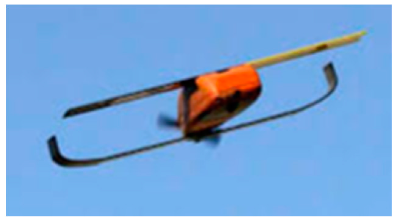
Since 2004, there have been a variety of small to large tube-launched drones. Small tube-launched UAVs, also known as micro autonomous vehicles (MAVs), are those that deploy from an approximately 0.041 m diameter by 0.154 m long tube. Due to their small size, they have been designed and utilized as portable short-range ISR drones by soldiers on the ground. Given these size limitations, innovative folding devices are required to achieve adequate stability and meet mission objectives while remaining compact and foldable. One of the most prominent examples of this UAV class, of the many seen in the references [2,3,4,5], is the Perdix swarm drone that was developed by MIT and the Strategic Capabilities Office (SCO) [2]. Figure 1 shows the MAV design from MIT.

Figure 1.
Perdix MAV from MIT [2].
The MIT MAV was designed to be tube-launched from aircraft or ground troops, and then link up in swarms of multiple drones that operate on a collective brain. With an endurance of 20 min, Perdix drones can conduct low altitude, short-range ISR after being deployed. This drone, when unfolded, is a tandem wing design, as seen in Figure 1, utilizing a bi-fold mechanism with a wingspan of 0.300 m, length of 0.165 m, and weight of 0.290 kg [2]. In a test environment, as many as 100 of these drones were deployed in a swarm, which then conducted several simple, short-range missions to display sufficient functionality [2].
Large tube-launched UAVs expand on the capabilities of MAV UAVs. These are UAVs designed to be deployed from a tube in flight from aircraft/helicopters or rocketed from the ground. For this scale, a tube size of 0.124 m in diameter and 0.813 m in length is commonly used, about the size of an A-class sonobuoy [6]. This larger scale offers much more capability than the MAV scale UAVs in terms of range and performance.
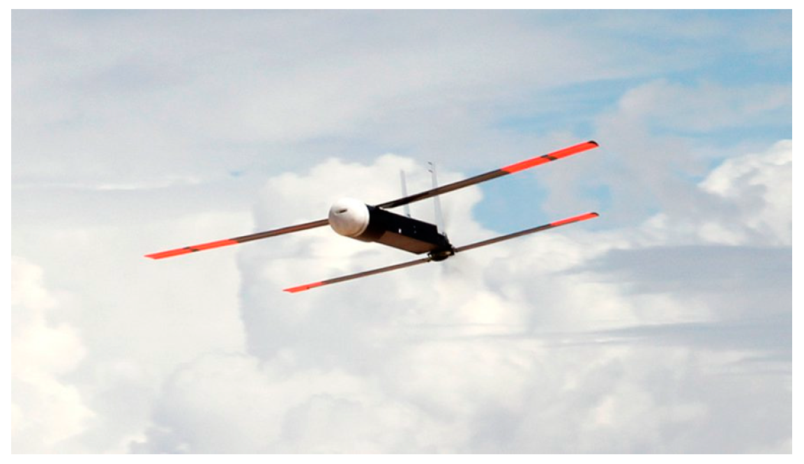
An example of one of the many larger tube-sized drones (see references [6,7,8,9,10,11]) is the Raytheon Coyote seen in Figure 2. A competitor of the previously mentioned STTR request from the Navy, it has a range of 200 km and an endurance of 90–120 min [10]. Designed to perform ISR missions in its unfolded configuration, it is a tandem wing aircraft with a 1.494 m wingspan, bi-fold wing mechanism, and a fuselage length of 0.914 m, flying at a max weight of 5.896 kg [9]. This UAV also utilizes a pusher propulsion system. The Coyote uses elevons for its control surface and does not have rudders or ailerons. To date, the Coyote has had a successful history in both military and civilian applications, including the National Oceanic and Atmospheric Administration [9].

Figure 2.
Raytheon Coyote [7].
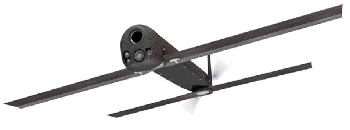
Medium tube-launched UAVs, as illustrated in references [12,13,14,15], are larger than MAVs, but do not have the same capabilities as large tube-launched UAVs. A medium tube-launched UAV uses a 0.124 m diameter and 0.419 m long tube, which coincides with the dimensions for a G-sized sonobuoy canister [6]. A distinct example of the medium size tube-launched UAV is the AeroVironment Switchblade 300 (Figure 3).

Figure 3.
AeroVironment Switchblade 300 [15].
The Switchblade 300 seen above, has a range of approximately 10 km and an endurance of 15 min [12]. It meets these performance parameters by using a tandem wing design with a bi-fold mechanism, a pusher propeller, and a wingspan of 0.687 m with a weight of 2.495 kg [12]. The Switchblade’s lack of range and endurance is likely due to its large explosive payload. This UAV has been produced since 2011 and is being used in various military applications. Due to the nature of the Switchblade’s mission, this drone is not available commercially.
As illustrated in the preceding paragraphs, tube-launched UAVs are a recent development and relatively few related papers (see references [2,3,4,5,8,14]) have been published. Current production aircraft, as illustrated in references [6,7,9,10,11,12,13,15], are used primarily for military applications, so most design details are unavailable to those with an interest in developing tube-launched UAVs for civilian applications.
Launch UAV is a student-led senior engineering student capstone team from Embry-Riddle Aeronautical University, Prescott, that seeks to fill the need by documenting the design challenges and trade-offs inherent in this class of vehicle. Launch UAVs’ design work is validated through a successful flight test program accompanied by the lessons learned after testing that will aid future designers of tube-launched UAVs.
2. Concept of Operations
The mission stages of the UAV, affectionately known as the Flying Fish due to its fish-like fuselage shape, can be enumerated as follows: release, unfold, reconnoiter, and recover. In the first stage of release, the Flying Fish, while still encased in a G-sized sonobuoy canister, is released from a larger aircraft that ferries the UAV above its target altitude. In stage two, the parachute is deployed to pull the UAV out of the canister. As the Flying Fish continues through the unfolding stage, the lifting and control surfaces unfold, reconfiguring the UAV into a flight-ready, fixed wing aircraft. In the reconnoiter stage, the UAV searches for people and identifiable objects. When flying, the UAV will transmit information such as video and telemetry data to remote operators. The Flying Fish will be airborne for a minimum of 45 min and will cover a range of at least 80 km while cruising at 2134 m MSL. Lastly, the UAV will enter the recovery stage. Once the mission has been completed, the UAV will be retrieved on the ground with a net-recovery system. The UAV will then be retrieved and repackaged into the sonobuoy container for the next mission.
Requirements
The main requirements for the aircraft’s design were given in a Request For Proposal (RFP) by the course instructor. Table 1 lists the given requirements. A requirement with a D at the end of the requirement code is a desired requirement, which may be outside the scope of this design.

Table 1.
Given requirements.
The given requirements focused on how the aircraft would fit inside of the G-sized sonobuoy canister and perform its mission. The derived requirements, shown in Table 2, were created by using the given requirements and considering the perspectives of key stakeholders.

Table 2.
Derived requirements.
While these derived requirements further define the UAV, additional performance specific requirements are needed. Table 3 shows the propulsion requirements.

Table 3.
Propulsion requirements.
The propulsion requirements provide preliminary design information for the propulsion system, ensuring that the aircraft can meet the performance requirements described in the given and derived requirements.
3. Disciplinary Design
Using the requirements outlined in Section Requirements, the design of the Flying Fish was developed by each individual design discipline: aerodynamics, stability and controls, propulsion, structures, performance, and manufacturing. Performance estimation is completed using a variety of analytical and semi-empirical methods. These methods are adapted from the research and results of references [16,17,18,19,20,21].
3.1. Aerodynamics
3.1.1. Aerodynamic Requirements
The primary requirement driving the aerodynamic design of the Flying Fish was the need to have the aircraft fold and fit in a G-sized sonobuoy canister. The canister’s length of 0.42 m set the maximum possible wingspan at 1.26 m if using three folding wing segments that extend the entire length of the tube. The canister’s diameter of 0.124 m means that the maximum possible chord is 0.096 m when three wing sections are stacked up. The other major requirement that influenced the aerodynamic design was the requirement to operate the aircraft between sea level and 3658 m MSL. Based on the concept of operations, any design decisions also contributed to achieving the desired range and endurance of 80.5 km and 45 min.
3.1.2. Wing Design
Given the requirements outlined in Section 3.1.1, the wing was designed to provide enough lift for the design weight at cruise, while minimizing the amount of drag produced to meet range and endurance requirements.
Based on the design weight and estimated cruise velocity of the UAV, a 2D coefficient of lift (Cl) of 0.58 at a Reynold’s number of 127,000 was determined to be the design target. A wide range of high lift airfoils optimal for low Reynolds number applications were compared using a panel-method solver. All results were verified using published low Reynolds number wind tunnel data. Due to limited space in the tube to mount the wing at an incidence angle and the desire to operate at an angle of attack (AoA) of zero to minimize drag, the Cl and coefficient of drag (Cd) at zero degrees were the critical values compared between airfoils.
Another consideration during the airfoil selection process was the thickness of the airfoil and its relation to the thickness of the servos housed in the wing. To minimize unnecessary drag, it was preferred to house the servo in the wing. The smallest readily available servos that could provide enough torque to operate the ailerons at maximum dynamic pressure have a thickness of 0.0099 m.
After comparing many airfoils, the Wortmann FX63-137 airfoil was found to be the best airfoil for the Flying Fish. The airfoil achieves a Cl of 0.589 at level cruise while only having a maximum thickness of 11.3 mm at the design chord of 82.5 mm. The aerodynamic data for the airfoil were evaluated using XFLR5 and compared to published low Reynolds number wind tunnel data [22].
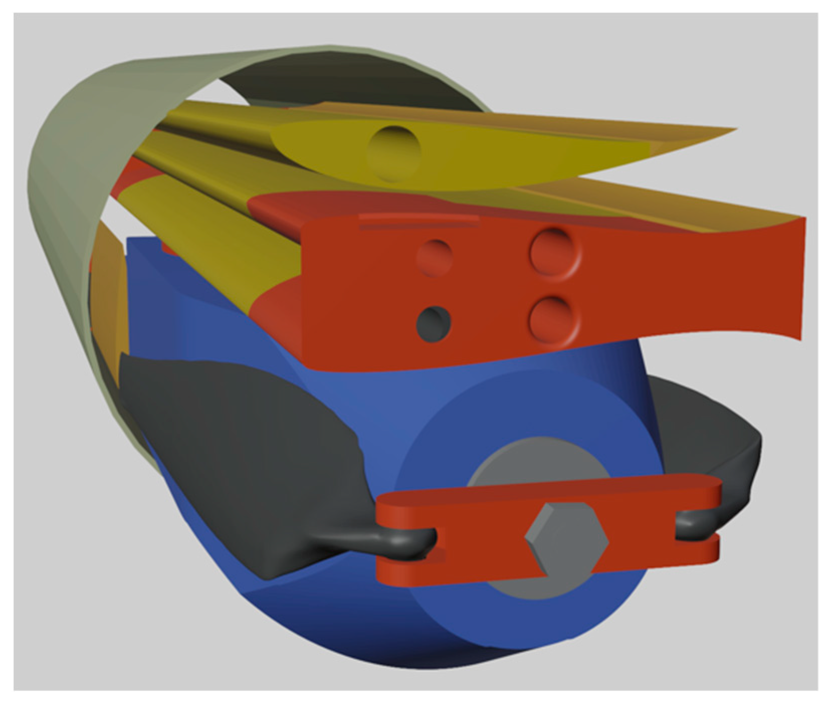
The initial sizing for the three-dimensional (3D) wing came from the space constraints inside of the G-sized sonobuoy canister. The two wing options considered were bi-fold and tri-fold designs. The bi-fold design could only have a maximum span of 0.711 m, which would result in a 0.089 m chord based on the diameter constraint. To reduce wing loading, a tri-fold design was determined to be the preferred option. In comparison to the bi-fold wing, the tri-fold design reduced the stall speed by 3 m/s, from 19.8 m/s to 16.8 m/s, which allows the Flying Fish to fly slower missions and be recovered at a lower velocity. Additionally, the tri-fold design increased the range and endurance. A further performance comparison of the two designs is presented in Section 3.5. Based on the folding method for the wings discussed in Section 3.4, the wings could include a middle section that is 0.381 m long and two outer sections that are 0.356 m each. This meant the new wing could have a wingspan of 1.093 m when fully deployed. To ensure clearance when slipping out of the canister, a chord of 82.6 mm was selected, allowing 6.35 mm of clearance between the wings and canister wall. The resulting wing has a planform area (Sref) of 0.090 m2 and an aspect ratio (AR) of 13.23. A rendering of the final wing design fitting inside the canister can be seen in Figure 4.

Figure 4.
Folded airplane inside canister.
Because the three wing segments are stacked vertically in a confined space when folded, as seen in Figure 4, the decision was made to not include any dihedral, incidence, or aerodynamic twist. Taper was not added since it would reduce the wing area and lead to a higher-than-optimal wing loading.
3.1.3. Drag and Performance Estimates
As noted in reference [23], XFLR5 provides appropriate trends, but must be corrected for real conditions. Since XFLR5 could only provide good data for the wings, a drag buildup code, adapted from Antoine et al. [16] for use with small UAVs, was developed to predict the total drag. This code estimates the parasite drag, lift-dependent skin friction and pressure drag, and induced drag. The parasite and lift-dependent skin friction and pressure drag was obtained from a 3D panel method solver that used lifting line theory and the vortex lattice method. The 3D wing designs were analyzed at a range of Reynolds numbers, and the resulting CD versus CL data were turned into a 3D lookup table. For the fuselage, the fuselage dimensions, skin friction, and form factor were used to determine its respective drag component. The drag due to surface roughness was accounted for by assuming an additional 25% drag increment. The induced drag component for the aircraft was found using the span efficiency factor of the wing calculated using the span-wise lift distribution. The induced drag was also corrected for fuselage effects that considered the width of the fuselage relative to the wingspan. Miscellaneous drag effects were accounted for by assuming additional components will account for 5% of the total drag. The total drag coefficient at cruise was calculated to be 0.0747.
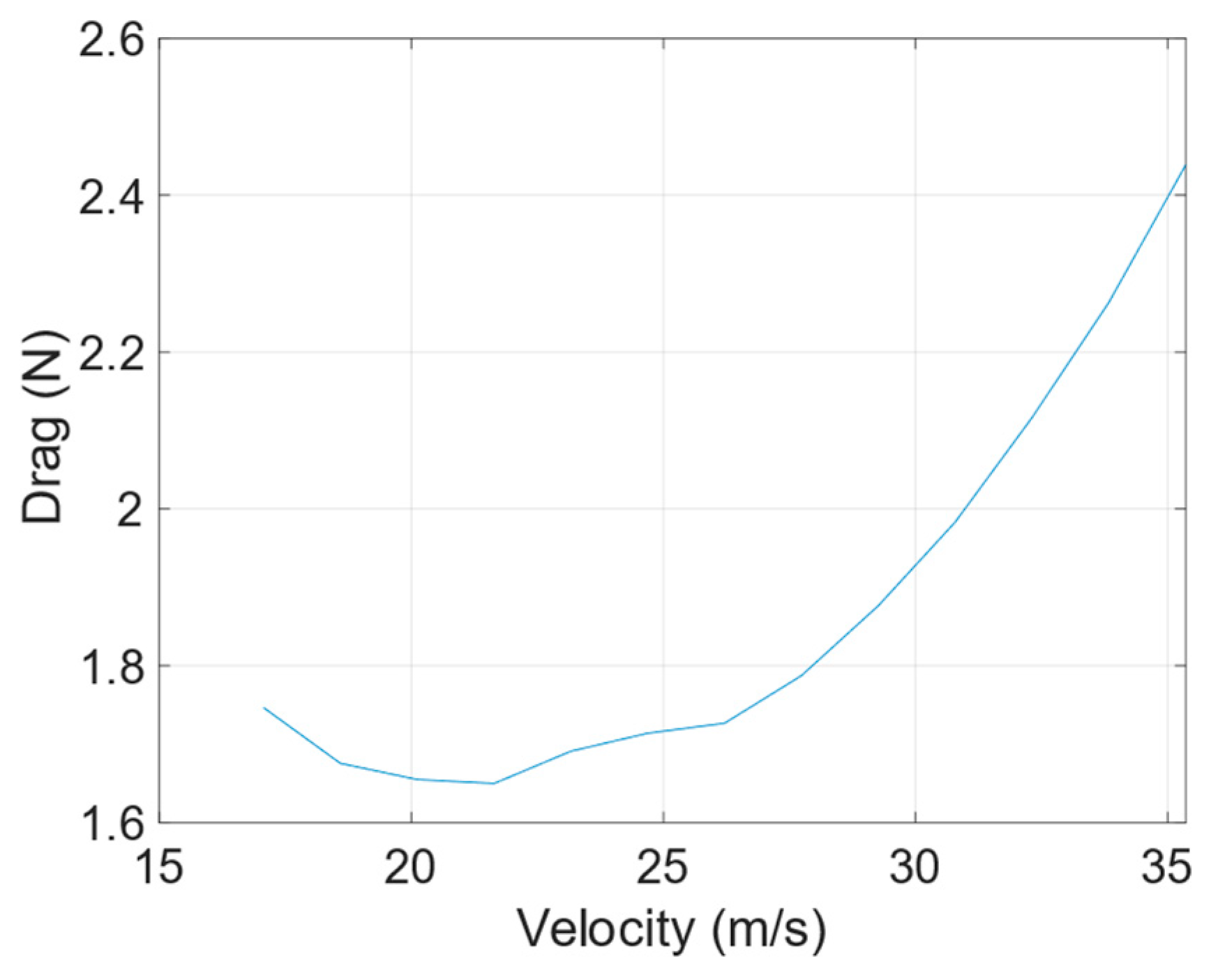
The drag experienced by the aircraft varies with velocity. Figure 5 shows the total drag versus the cruise velocity.

Figure 5.
Full aircraft drag prediction vs. velocity (FX 63-137 at 2134 m).
Figure 5 illustrates that the minimum drag of 1.65 N is achieved at 22.3 m/s.
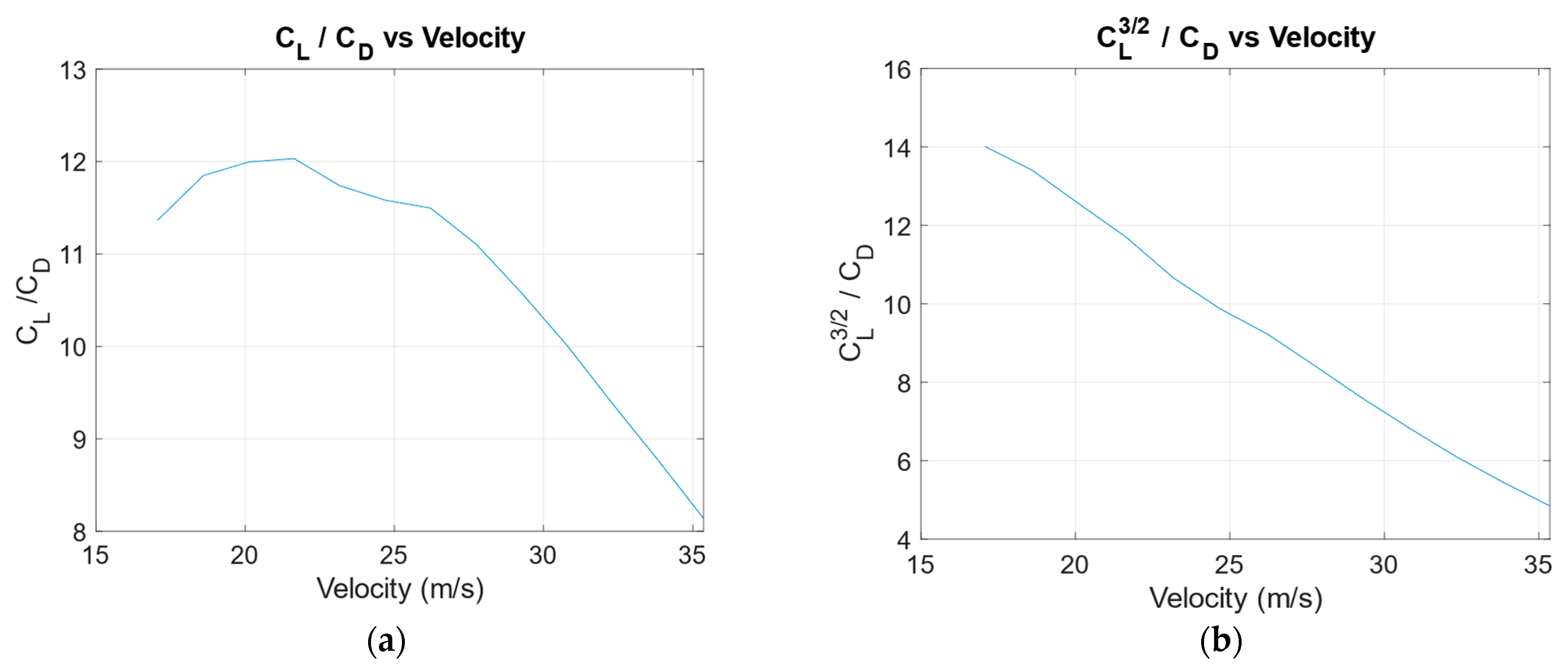
Based on the results of the drag buildup code, the overall performance of the aircraft was analyzed. The relationship between lift and drag was used to identify the ideal velocity for achieving the maximum possible range and endurance. The resulting plots, generated at the cruise altitude of 2133.6 m, can be seen in Figure 6.

Figure 6.
Full aircraft range and endurance parameters. (a) Range parameter versus velocity; (b) endurance parameter versus velocity.
The maximum possible CL/CD is 12.1 and corresponds to a velocity of 22.3 m/s, as seen in Figure 6a. This means that a cruise speed of 22.3 m/s will result in the maximum range possible [17]. On the other hand, the maximum endurance parameter (CL3/2/CD) of 13.9 occurs at the aircraft’s stall speed of 16.8 m/s, as seen in Figure 6b. The final cruise velocity of 22.3 m/s was selected after the range and endurance analysis described in Section 3.5.
3.1.4. Aerodynamic Summary
The Flying Fish has a wing with an FX 63-137 airfoil, a wing area of 0.090 m2, an aspect ratio of 13.23, and a taper ratio of 1. The wing was combined with the tails and fuselage as part of a drag buildup, which yielded a coefficient of drag at a cruise of 0.0747. The drag of the fuselage was verified using wind tunnel testing, discussed in Section 4.2, while the overall aerodynamic performance was evaluated through full-scale flight testing, as discussed in Section 4.3.
3.2. Stability and Control
The requirements for aircraft stability and control were derived from the RFP. The main requirement to fulfill is that the stabilizers must fold to conform to the constraints of the G-sized sonobuoy canister.
3.2.1. Stability and Control Requirements
The physical constraint limits the maximum span of the stabilizers. A static stability analysis is crucial to determine whether such constraints allow for a stable aircraft. The aircraft must also display sufficient control authority throughout its flight envelope. Although it is not an explicit requirement for the aircraft to be statically stable, aircraft stability is an implicit goal, as it would be helpful to conduct flight testing of a stable aircraft as opposed to an unstable aircraft without active control measures.
3.2.2. Tail Design and Control Surface Sizing
The size constraints of the Flying Fish were the main factor for consideration in the tail design layout. Twin vertical tails were selected as they are able to fold easily along the fuselage. The vertical tails were treated as one total stabilizer for calculations, as recommended by Raymer [18]. The aspect ratios chosen for both the vertical and horizontal stabilizers are within the valid range of the Polhammus formula to estimate their 3D lift curve slope, , which is used in the calculation of the stability derivatives. Table 4 displays the geometric parameters for the tail.

Table 4.
Tail configuration.
The design for the tail involved using vertical and horizontal tail volume coefficients ( to size the tail. Historical data suggest a range for from 0.35 to 0.5 and a range from 0.02 to 0.04 [18]. Typical tail sizing reflects the fact that the tail area is embedded in the fuselage. However, the Flying Fish has an abnormally large fuselage at the point where the tail connects to the body. Thus, the areas for the horizontal and vertical stabilizers used in the volume coefficient equations reflect the planform areas exposed to the freestream air. The tail configuration parameters from Table 4 yield a of 0.45 and a of 0.028, both within the recommended range.
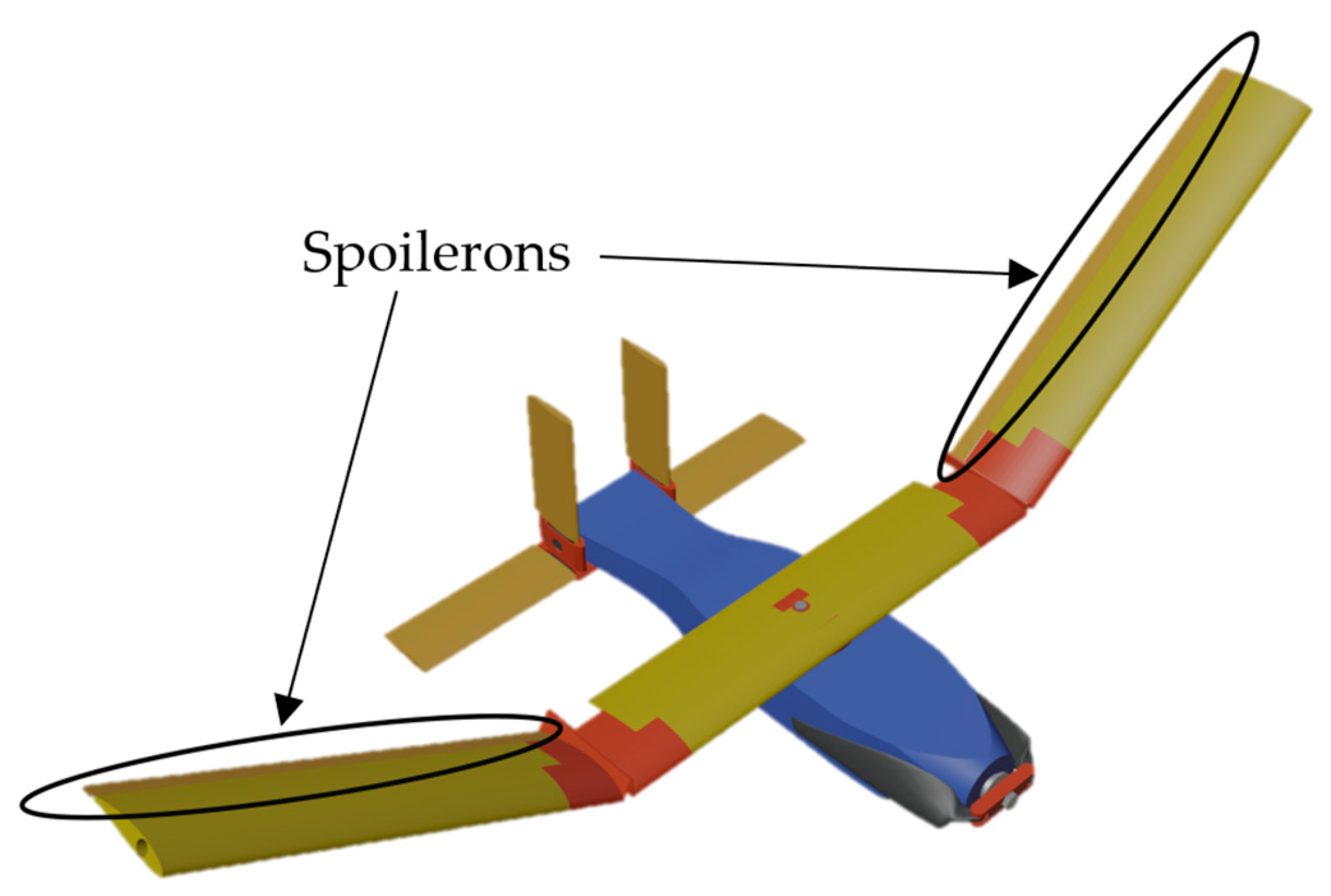
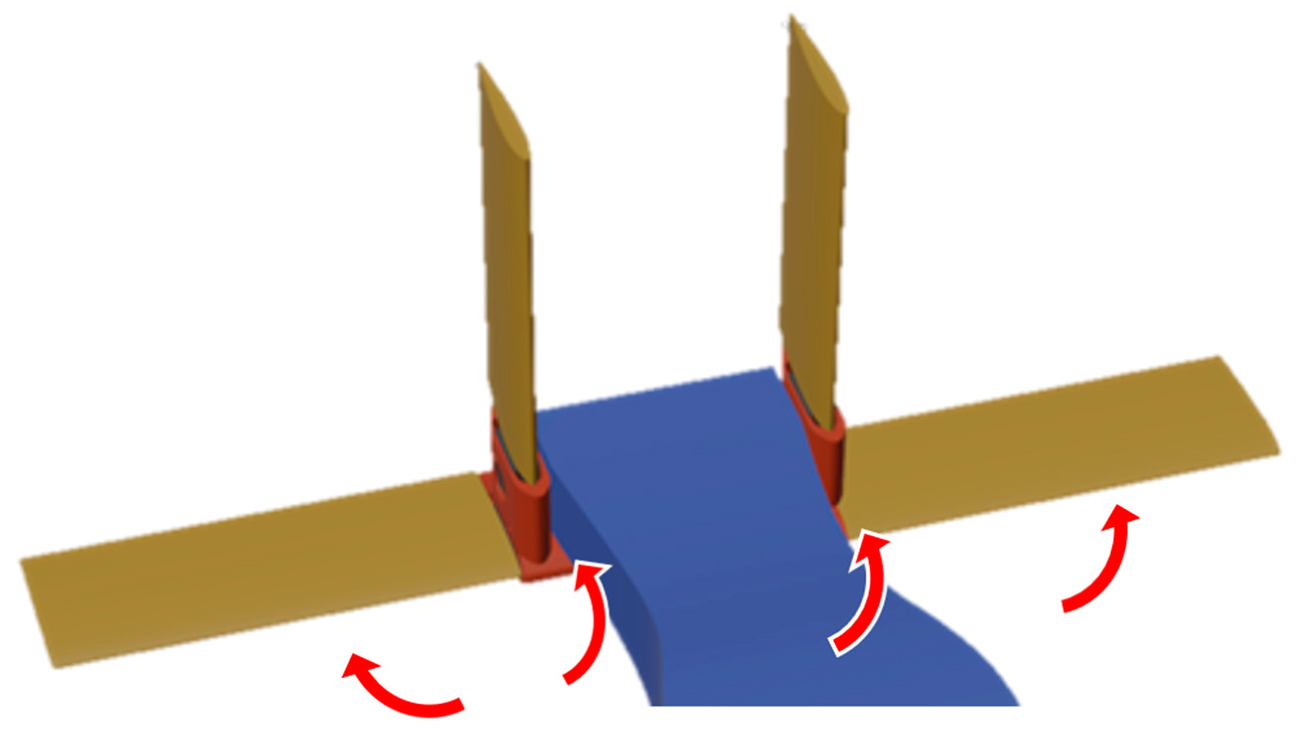
One of the primary areas of concern in the deployment of the Flying Fish is when the aircraft falls out of the canister and unfolds its wing and stabilizers. This maneuver is detailed in Section 3.5. As the wings unfold, the natural lifting direction of the wing impedes the unfolding action as the wing attempts to unfold over itself. To ensure that the wing unfolds, spoilerons on the wing will prevent the lift from counteracting the direction in which the wing unfolds, as shown in Figure 7.

Figure 7.
The wing mid-deployment.
The spoilerons are 20% of the chord and 63% of the span, as seen in Figure 7. They were sized from a combination of historical guidelines and car testing. Car-top testing was conducted, with the car starting at 20.1 m/s and decelerating until the wing was able to open, deploy, and lock. With no spoilerons, the wing opened, deployed, and locked at 2.23 m/s. With spoilerons, the wing was able to open, deploy, and lock at 11.2 m/s. Further testing of the spoilerons is recommended to ensure that unfolding and locking will occur during the pullout maneuver that occurs upon the jettison from the G-sized canister. Greater detail of the refined mechanical folding mechanism is provided in Section 3.4.2.
The Flying Fish is outfitted with all-moving rudders and all-moving elevators. All-moving surfaces were selected to provide enough control authority for the aircraft to pull up during the 2 g pullout maneuver. In addition, all moving control surfaces are easier to manufacture at the scale of this UAV. Raymer suggests that a full 6 degree of freedom dynamic analysis is required to determine whether the control surfaces are sufficient in size to provide the proper control authority the aircraft needs throughout its flight regime [18]. Due to time constraints, the team decided to prove the Flying Fish’s control authority in the 2 g pullout maneuver through flight testing. It was shown through flight testing that the pitch authority was sufficient for pullout, allowing for the transition to steady level flight at the terminus of the maneuver.
3.2.3. Stability
Static stability was determined using four parameters: static margin (SM), the coefficient of pitching moment due to AoA (), the coefficient of yaw moment due to sideslip (), and the coefficient of roll moment due to sideslip . To be stable, the following criteria must be met: SM must be positive, must be negative, must be positive, and must be negative. These stability derivatives, as well as the static margin, were found using equations from Napolitano’s Aircraft Modeling and Simulation [19] and calculated at the cruise condition. Table 5 displays these key parameters. One key assumption made was that the fuselage did not generate any lift and its contribution to the aircraft’s aerodynamic center was negligible. This assumption was validated through the wind tunnel testing of the fuselage. It should be noted that the values acquired from using Napolitano’s equations are estimations derived from larger aircraft. Thus, the team decided to learn more through flight testing for validation.

Table 5.
Static margin and static stability derivatives.
The Flying Fish’s static margin is estimated to be 0.15 and the aircraft’s aerodynamic center is predicted to be 0.178 m aft of the nose. During flight testing, it was shown that the actual aerodynamic center lies more forward than predicted. The center of gravity, CG, was then moved to 0.136 m aft of the nose, from the original CG location of 0.165 m. was calculated to be −1.554 (rad−1). The negative value means a small disturbance will result in the aircraft pitching back to steady level flight. These values predict that the aircraft is longitudinally stable, which was validated through flight testing.
The incidence of the horizontal tail at cruise, , was calculated to be −3.4°. The incidence of the horizontal tail can be experimentally derived through flight testing since it is fully variable.
For lateral/directional stability, was calculated to be −0.071 (rad−1) and was calculated to be 0.138 (rad−1). These values satisfy the stability criteria. The main contributor to is the high-mounted wing. However, is not in the range for typical aircraft, which is −0.28 to −0.082 [19]. However, adding 5° of dihedral would change to −0.09, which would be within the typical range. To add any amount of dihedral to the main wing, a proposed idea involved cutting the tips of the center portion of the main wing at an angle, resembling a bevel cut.
Despite being statically stable, the flight test results demonstrated that the Flying Fish is sensitive to environmental conditions, roll and spiral instability, and over-control. Details of flight testing are discussed in Section 4. Sensitivity to environmental conditions and roll instability is likely due to a low roll mode time constant and not having enough roll stability, despite the high-mounted wing. A solution to this problem could be to incorporate polyhedral on the outboard wings to increase the roll stability and push into the nominal range for typical aircraft. The Flying Fish’s spiral instability was predicted using the Blaine Rawdon parameter, B, as shown in Equation (1).
In the equation above, Υ is the dihedral of the wing in degrees, is the vertical tail moment arm, b is the wingspan, and is the lift coefficient. To be considered spirally stable, B must be greater than five. Since the current design of the Flying Fish does not incorporate dihedral, the corresponding Blaine Rawdon parameter becomes zero. However, 15° of dihedral yields a value of 5.03, predicting that the aircraft would be stable in the spiral mode. Launch UAV made the decision to not include dihedral to not reduce the wing planform area. The reduction in the planform area would have increased the aircraft’s stall velocity, which was already relatively high for an aircraft of its size. With no dihedral, the aircraft would have to avoid the spiral mode through pilot skill and the pilot’s corrective inputs.
To address the problem of being over-controlled, the receiver used during flight testing incorporated control limiters for all control surfaces. The limits were derived experimentally, where the spoilerons were limited to ±10°, elevator to ±30°, and rudder to ±5°. Being over-controlled is a direct result of the all-moving elevator and rudder as well as oversized spoilerons relative to other aircraft.
3.2.4. Conclusion
The results from the empirical analysis denote that the aircraft is statically stable according to the stability criteria. The stability was validated through flight testing, where steady level flight and sufficient control authority were demonstrated. The current design of the Flying Fish also meets the requirements to keep the stabilizers within the size constraints of the canister. Further developments should focus on changing to be in the upper end of the range for typical aircraft, as well as polyhedral wings, which might decrease the Flying Fish’s sensitivity to environmental factors and roll instability. These stability parameters could be verified using a similar approach to the research completed in reference [24] in order to develop a control law and remove the burden from the pilot.
3.3. Propulsion
The requirements that were provided and derived at the start of this project also apply to the propulsion system. The UAV was designed to meet speed, range, and endurance requirements, creating a baseline for propulsion system performance that was fulfilled through preliminary analysis and experimental testing.
3.3.1. Initial Requirements
The requirements for propulsion are based on a minimum flight speed of 16.8 m/s, an estimated cruise speed of 22.3 m/s, a minimum range of 80 km, and minimum endurance of 45 min. Due to the size-constrained fuselage, an electric power system was determined to be the most efficient and easiest to integrate. To ensure the reusability of the system, rechargeable lithium polymer (LiPo) batteries were selected. The diameter of the G-sized canister also constrained the size and type of propeller, making a foldable propeller a requirement since the propeller diameter would exceed the canister diameter.
3.3.2. Preliminary Analysis
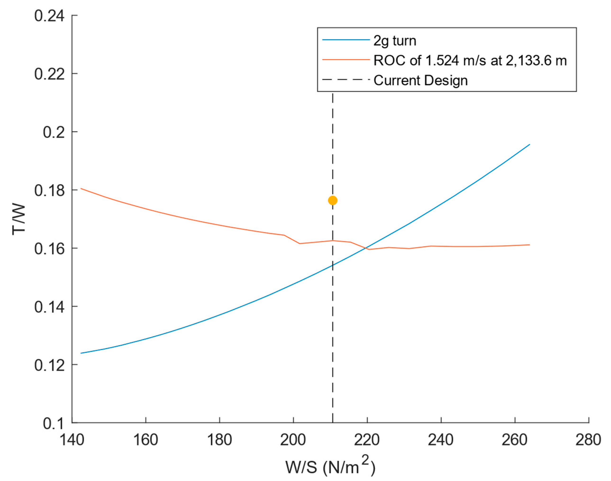
After deriving the propulsion requirements, a preliminary analysis was conducted to determine the initial sizing of the propulsion system, including propeller dimensions, battery power, and motor size. A key component in this analysis was wind tunnel data obtained and published by the University of Illinois Urbana-Champaign (UIUC) [20] and APC Propellers [21], which provide a variety of performance parameters. After predicting the minimum thrust and power required, a propeller configuration was chosen from the APC data to exceed the minimum required thrust and power while being able to achieve the minimum range and endurance requirements. Figure 8 shows the thrust-to-weight (T/W) design point for the aircraft, which is slightly above the 2 g turn and rate of climb (ROC) requirements.

Figure 8.
Aircraft thrust/weight vs. wing loading.
The T/W design point was calculated using the static thrust value obtained through published test data for the chosen propeller at the cruise revolutions-per-minute (RPM) of 5000. At cruise, the propulsion system provides a T/W of 0.177 as seen in Figure 8, indicated by the yellow dot.
3.3.3. Propulsion System Components
The final propulsion system configuration consists of components that would fulfill all given and derived propulsion requirements. Table 6 gives a brief overview of each component and its key specifications.

Table 6.
Overview of propulsion components.
The chosen propeller was a 330 mm diameter by 254 mm pitch folding propeller from APC. It has a high pitch-to-diameter ratio as well, which allows it to perform better at high airspeeds and RPMs. The motor is a 770 Kv Eflite Power 32 brushless electric motor, which was chosen because it provided the required number of RPMs using a 11.1 V battery. The battery consists of two rechargeable Ovonic Air 11.1 V, 8000 mAh Li-Pos, which provide a total battery capacity of 16,000 mAh.
3.3.4. Testing and Verification
To ensure that the predicted values for thrust, speed, and endurance were correct, several experimental tests were performed with the intent of data verification. The propeller was tested for thrust production, which provided thrust values within 10% of the published data. The verification of these values led to the conduction of several other tests to validate the endurance of the propulsion system. Validation was achieved by observing the battery power levels while the motor was run at different RPM settings, with the most important being max RPM and cruise RPM. Table 7 gives an overview of the testing performed and a brief description of the corresponding procedure for each test.

Table 7.
Overview of propulsion tests.
During the endurance test, the motor drew an average of 9 amperes (A) from the batteries. Thus, the batteries are expected to provide approximately 83 min of flight time when discharge is limited to 80% of total capacity. The results of the testing verified that the predicted endurance and the endurance obtained from the experimental testing were within 10%, confirming the aircraft’s ability to meet the endurance requirement.
3.3.5. Expected Performance
For the full-scale production model at 1219 m, further discussed in Section 4, a cruise T/W of 0.177 and a maximum T/W of 0.91 were predicted. Overall, the expectation is that the propulsion system will perform as it was designed to, allowing for the fulfillment of all range, speed, and endurance requirements.
3.4. Structures
The Flying Fish had to meet three main structural requirements. First, the aircraft must follow the structural requirements detailed by NATO Standards [25]. Next, the Flying Fish must withstand the structural loads caused by the pullout maneuver, which is further explained in Section 3.5. Last, the aircraft must perform 2 g turns.
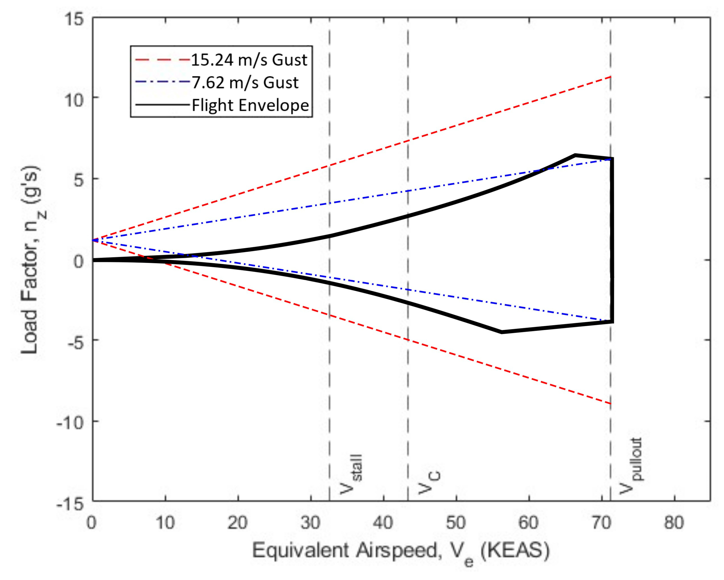
To determine the appropriate load factors that the aircraft may encounter, NATO Standard AEP-83 was referenced for the required minimum maneuver and gust limit loads [25]. According to the NATO standard, the aircraft must be able to withstand a positive load factor of 3.8 g and negative 1.5 g during normal flight operations. The aircraft must be able to withstand gusts of 15.24 m/s at cruise and 7.62 m/s at its maximum safe operating speed. These regulations were used to plot the vehicle’s flight envelope. Figure 9 shows the V-n diagram of the aircraft.

Figure 9.
V-n diagram.
As shown in Figure 9, the maximum design load factor is approximately 5.6 g, including when the aircraft is subjected to the maximum specified gust conditions. Unlike flight envelopes of larger aircraft, most of the Flying Fish’s flight regime is stall-limited rather than maneuver-limited. This prevented the envelope from expanding for gust conditions for all speeds within the positive and negative stall curves. Outside of the stall curves, the flight envelope was expanded by connecting the intersections of Vpullout and the 7.62 m/s gust line with VC and the 15.24 m/s gust line. These lines described for both positive and negative load factors were truncated at their intersections with positive and negative stall lines.
The maximum load factor that the aircraft can experience resulted in a bending moment of 20.34 Nm at the wing root. A spar for the main wing was selected with a sufficient tensile strength to withstand the maximum bending moment, including a factor of safety of 1.5. As a precaution, it was assumed the spar would carry all bending loads. This assumption led to Launch UAV specifying a main spar with a diameter that ensured safe operation in all flight regimes.
3.4.1. Fuselage
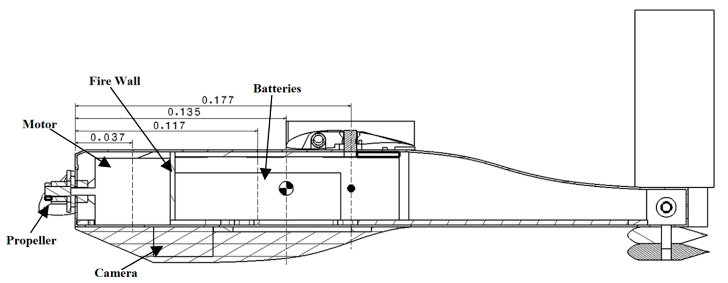
To fit inside of a G-sized sonobuoy canister, the fuselage must be compact while accommodating the payload and aircraft systems. With wind tunnel testing, discussed in Section 4.2, the fuselage was found to create more drag than predicted and the fuselage was modified to be more aerodynamic. The systems were placed in the fuselage to create the specific CG required for the desired SM. Figure 10 below shows a cross-section of the fuselage from the side and the locations of the internal components. All dimensions are in meters.

Figure 10.
Inside the fuselage.
The battery is placed 0.117 m from the nose with the aircraft systems around it and behind it, as observed in Figure 10. The motor is 0.037 m from the nose. Ballast could also be placed in the area where the battery is located to achieve the desired CG location of 0.135 m from the nose. The predicted aerodynamic center of the aircraft is 0.177 m from the nose. To access the internal components, a tail hatch was created along with the payload hatch to open the entire bottom of the fuselage.
3.4.2. Main Wing
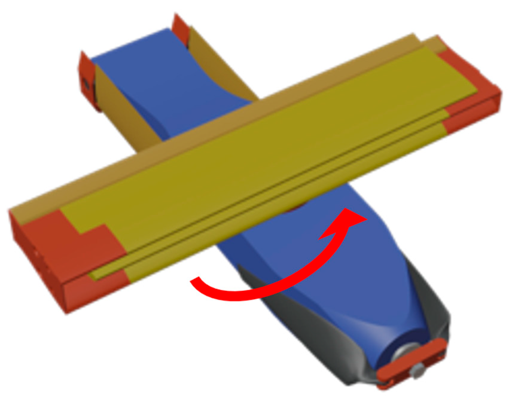
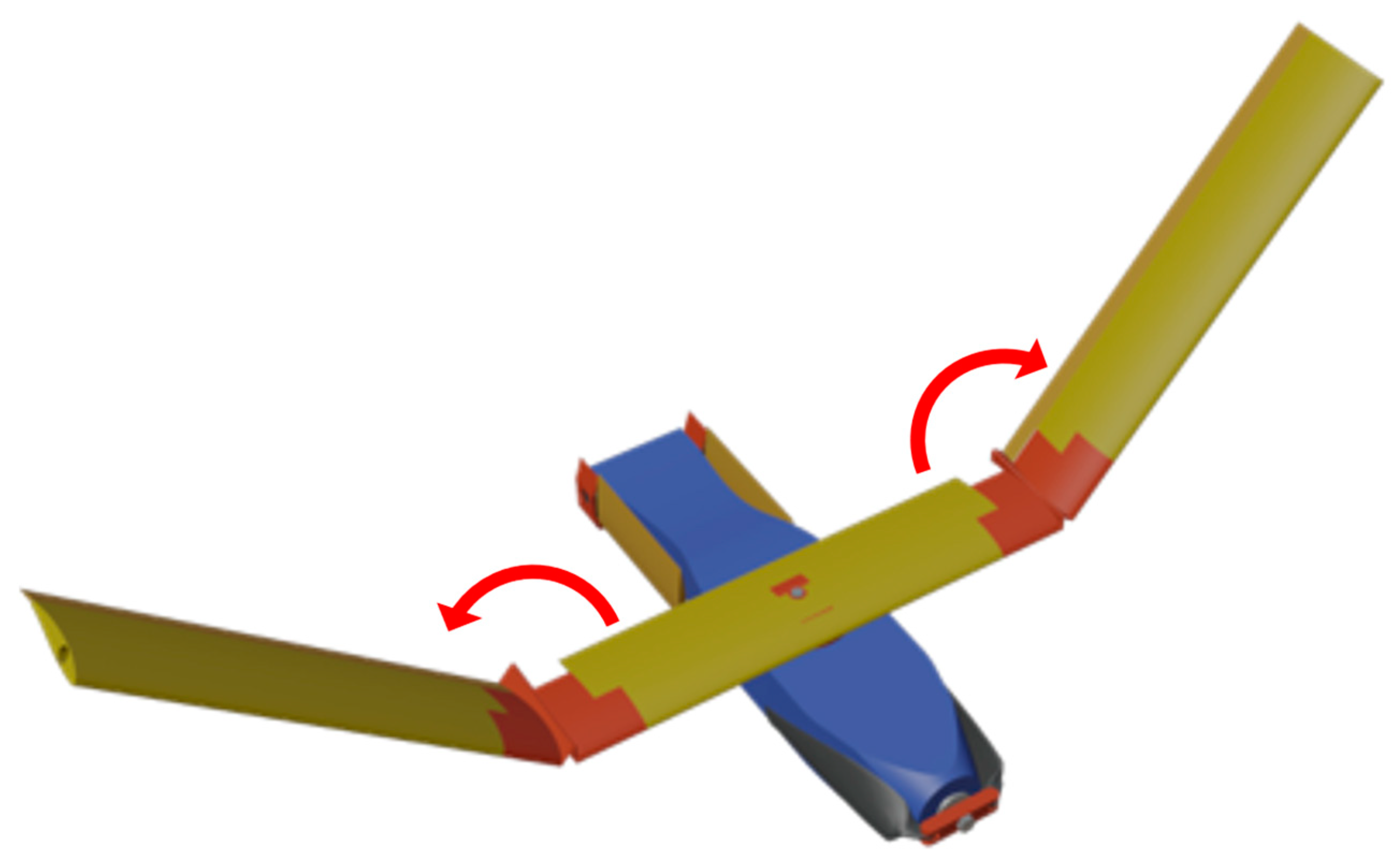
To achieve the 1.09 m wingspan while still fitting within a G-sized sonobuoy canister, the wing had to fold into three sections. Folding was achieved using two linear springs and one torsional spring. The torsional spring rotates the main wing from parallel to perpendicular relative to the fuselage, while two linear springs pull open the outboard wings into the flight-ready configuration. Figure 11 shows how the control surfaces fold out during deployment from the tube.

Figure 11.
Deployment and unfolding of Flying Fish.
The main rotational fold in the center of the wing, as shown in Figure 12, was 3D printed using Polyethylene Terephthalate Glycol (PETG). It was designed to have free rotation around the single attachment bolt while also having an integrated torsional spring and locking mechanism. This main folding mechanism is directly connected to the spar for increased structural rigidity. A locking mechanism keeps the wing in the flight-ready position until the user unlocks it to repackage the aircraft into the sonobuoy canister. Figure 12 shows how the main wing rotates 90° and locks in the flight-ready position.

Figure 12.
Center fold of main wing.
The other two folding mechanisms for the outboard wings are also 3D printed using PETG, seen in red on the outboard sections of the mid wing in Figure 12. The folds use a live Kevlar hinge with linear springs to facilitate the unfolding of the wing. From testing, it was determined that the springs, along with spoilerons, are effective at unfolding the main wing in flight; these tests are detailed in Section 3.2.2. Like the main fold, both outboard wing folds attach directly to the spar for structural rigidity. These folding mechanisms also require locking mechanisms that can keep the wing in the flight-ready configuration through all expected loads. The locking mechanism uses aluminum latches that are directly connected to both sides of the 3D printed part. Figure 13 shows how the outboard wings fold and lock into the flight-ready position.

Figure 13.
Outboard folds of main wing.
Both the main wing and outboard folding mechanisms, shown in Figure 12 and Figure 13, respectively, were also designed with the consideration of allowing servo wires to pass through without being pinched or hindering the unfolding process. The manufacturing of these parts requires a high level of precision to ensure functionality.
3.4.3. Tail Design
The tail section of the aircraft was designed to fold inward towards the fuselage to be able to fit inside the tube. Initially, the tails were designed with springs to actuate the unfolding of the tail surfaces. Figure 14 shows the tail section with the mounts that house the servos.

Figure 14.
Vertical tail.
As can be noted in Figure 14, the mounts are attached to the tail of the Flying Fish with bolts to pivot with the tail surfaces. Strings are attached to the top of the tails with clips, and to the inside of the tube. Once the aircraft leaves the tube, the strings pull the tails backward and the clips release from the tails. When the control surfaces are in the correct position, spring pins spring out into holes in the mounts of the tails and lock them into place.
3.4.4. Structural Summary
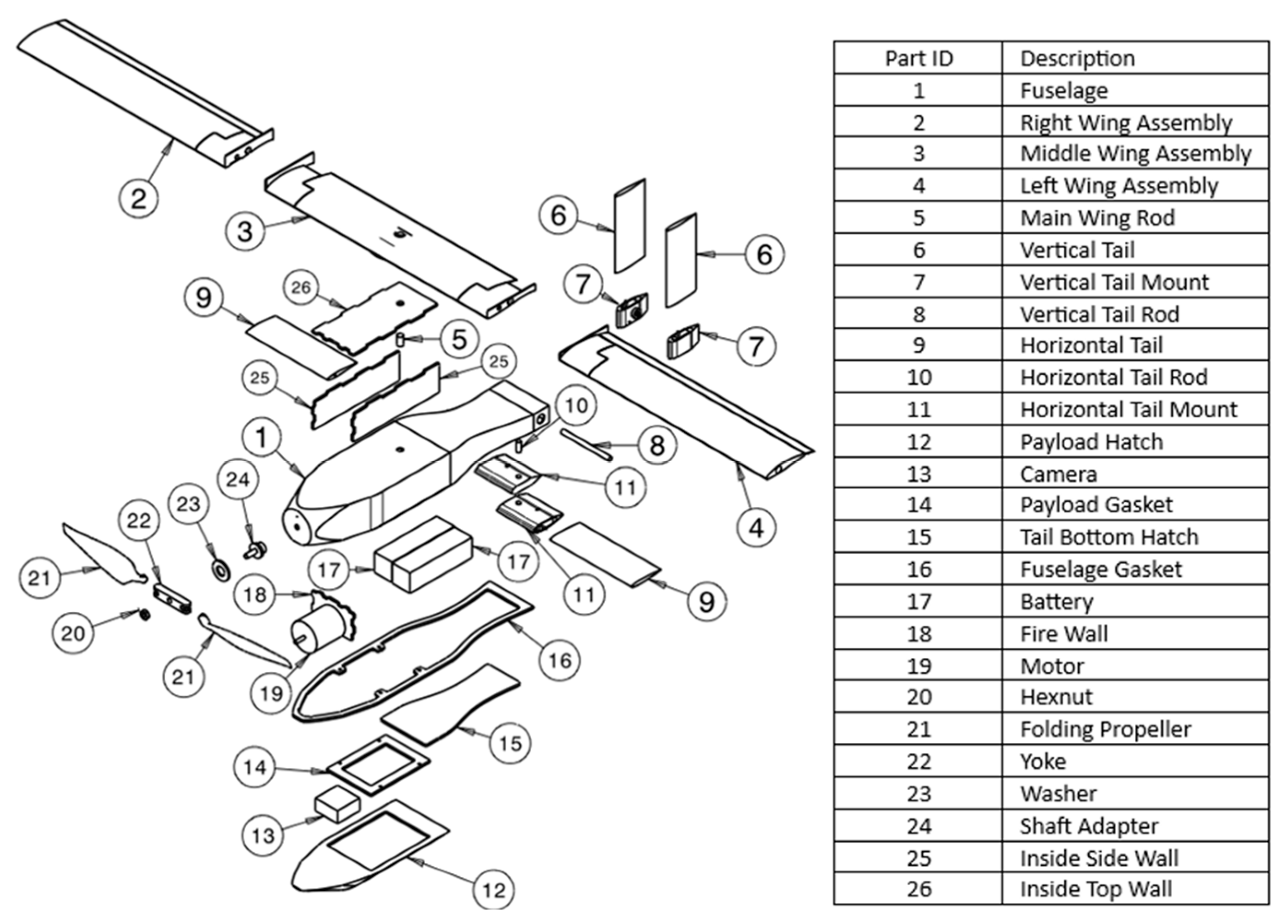
The Flying Fish contains the top half of the fuselage, payload hatch, main wing assembly, and tail control surfaces. An exploded view of the entire aircraft can be seen in Figure 15.

Figure 15.
Flying Fish exploded view.
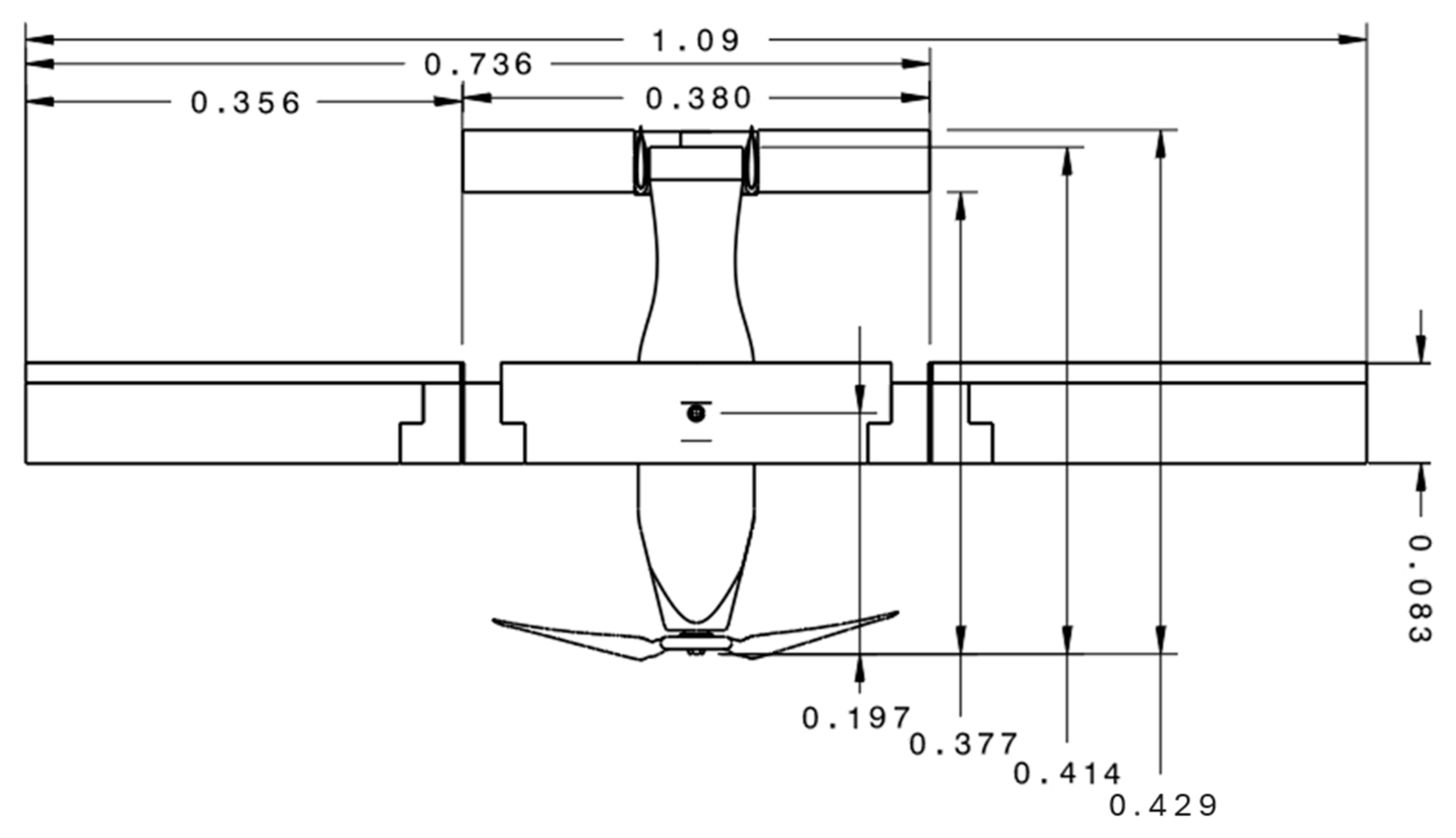
The fuselage, identified as Part 1 in Figure 15, holds all of the electronics and folding mechanisms. The wing consists of three sections that fold on top of each other. The vertical and horizontal tails fold to the sides of the fuselage. The overall dimensions, in meters, of the final version of the Flying Fish are shown in Figure 16.

Figure 16.
Flying Fish dimensions.
The fuselage is 0.414 m long, with a wingspan of 1.09 m and a chord length of 0.083 m, as noted in Figure 16. The vertical and horizontal tail effective spans are 0.114 m and 0.140 m, respectively, with both having chord lengths of 0.051 m. The folded aircraft fits within the G-sized sonobuoy canister with 6 mm of length clearance.
3.5. Performance
The aircraft performance analysis focused on ensuring the chosen wing design and propulsion system would allow the aircraft to meet the performance requirements. The major constraints analyzed when selecting the wing design and propulsion system were the 2 g turn and ROC requirements.
3.5.1. Rate of Climb (ROC)
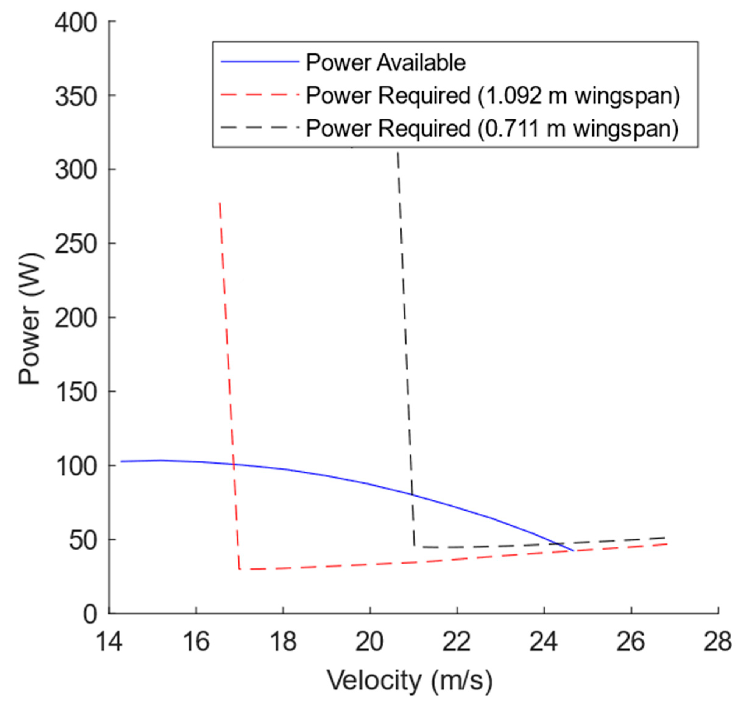
An important factor that determined the wingspan was the margin between the cruise and stall speeds. For a given weight, a longer wingspan will have a lower wing loading and a decreased stall speed. To select a cruise velocity, drag and power must both be considered. Higher velocities increase drag, but may increase range. Additionally, a heavier aircraft must fly faster to produce enough lift to sustain level flight. Figure 17 shows how power changes with velocity.

Figure 17.
Power required vs. velocity for two different wingspans.
The nearly vertical lines in Figure 17 reflect that the wing has stalled. The wing with a shorter span, seen in black, has a 4.6 m/s higher stall velocity than the wing with a longer span, seen in red. Thus, the smaller wing provides a much smaller flight envelope. Additionally, the power required at each airspeed is higher for the shorter wingspan, adversely affecting performance. The best ROC speed corresponds to maximum excess power, which occurs just before stall. ROC is calculated at the best rate of climb speed for each altitude. With a 1.092 m wingspan, the aircraft’s service ceiling is established at 6400 m, since this altitude is the point where the rate of climb drops below the minimum required ROC of 89.9 m/min. The propulsion system affects the ROC by changing the amount of power available: a more powerful propulsion system will increase the ROC and raise the service ceiling, but will be less efficient when cruising.
3.5.2. Range and Endurance
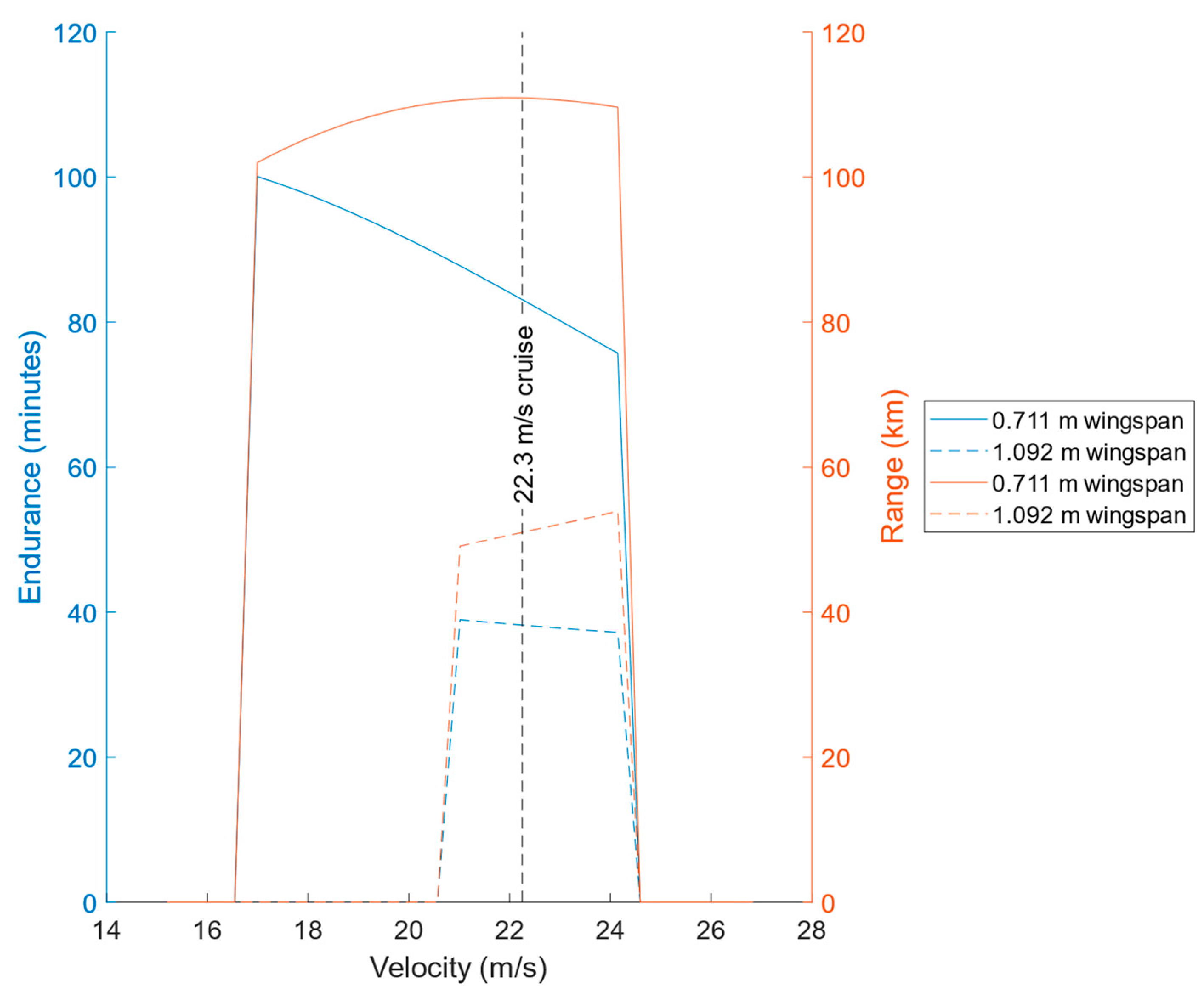
As velocity increases, the drag and power required increase, regardless of wingspan. To maximize endurance, the lowest velocity possible should be selected for cruise. Cruise velocity is restricted by stall speed, with shorter wingspans having a higher stall speed. The overall impact of wingspan on maximum range and endurance is shown below in Figure 18.

Figure 18.
Range and endurance vs. velocity for two different wingspans.
The range of each wingspan only varies by 16 km over the velocities shown in Figure 18, but the endurance for each wingspan decreases linearly with an increase in velocity—a lower cruise speed will have the best endurance. A wingspan of 1.092 m was chosen because it is the only wingspan that meets the range and endurance requirements. A cruise velocity of 22.3 m/s was selected to maximize the range and while meeting the endurance requirement. At this cruise speed, the Flying Fish has a range of 111 km and an endurance of 83 min, well above the required 80 km range and 45 min endurance.
3.5.3. Pullout Maneuver
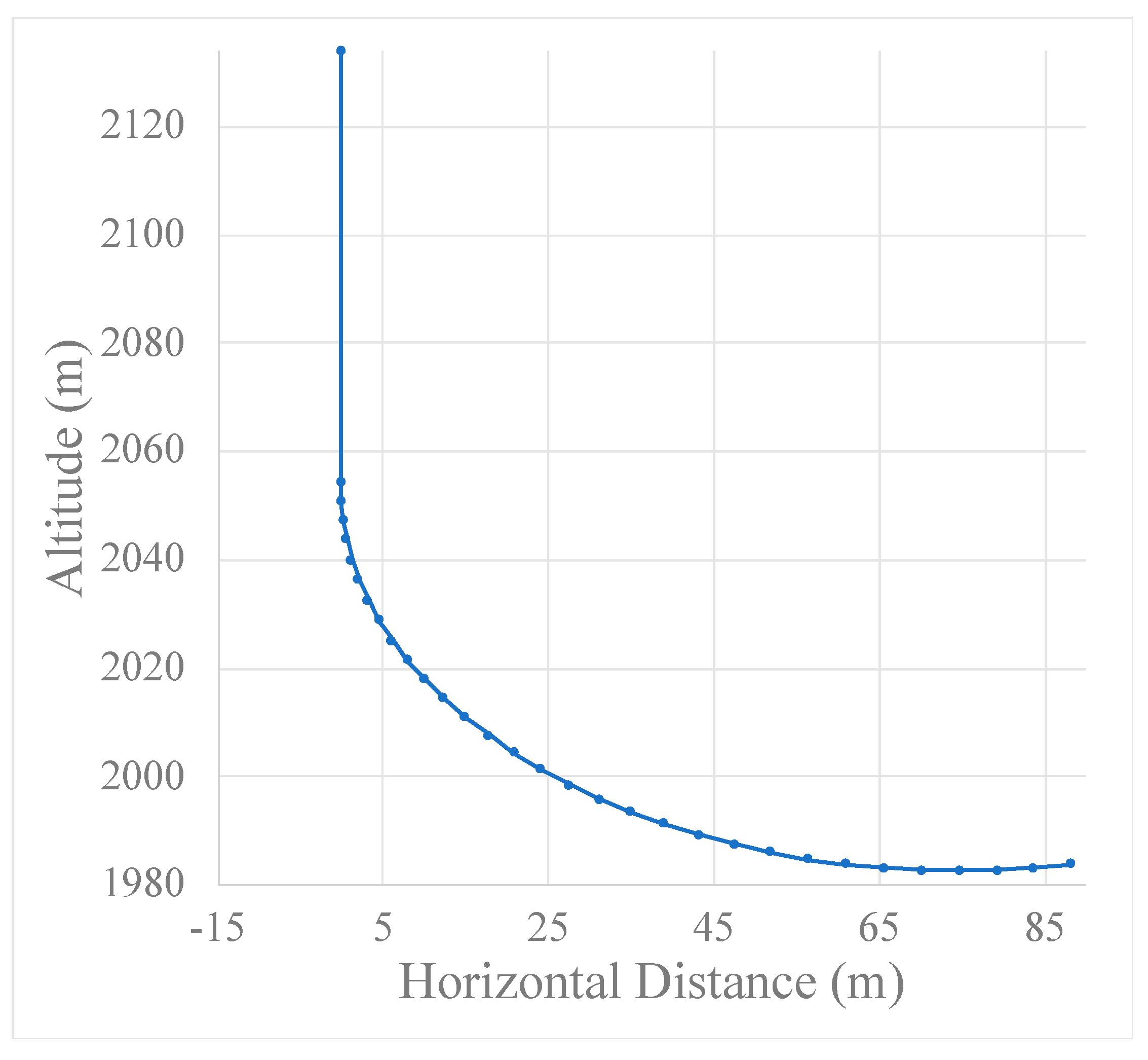
Launching the UAV from a canister required a pullout maneuver analysis. The total altitude lost before the aircraft can level out is affected by weight and drag, and is ultimately limited by the maximum load factor that the airframe can support. The launch trajectory, and, thus, the minimum height above the ground that the aircraft can be deployed, is dependent on both the wing loading and the control surfaces’ ability to generate the pitch rate required to follow a path that maintains a constant load factor. Figure 19 shows the trajectory of the aircraft when launched from 2134 m.

Figure 19.
Trajectory of aircraft when launched from 2134 m.
The pullout trajectory shown in Figure 19 assumes a deployment time of 4 s before the wings unfold and begin generating lift. During this time, the aircraft is falling with a small amount of drag, gaining velocity. A constant 2 g pullout results in a total vertical drop of 152 m before the aircraft is in level flight. The launch process is insensitive to an increase in drag. With a 15% increase in drag for both the deployment phase and the pullout maneuver, the total vertical distance covered is 150 m. The maximum velocity reached is the same. The launch process is far more sensitive to an increase in weight. With a 15% increase in weight, the total vertical distance covered is 163 m. The maximum velocity reached is 48.8 m/s, close to the maximum allowable dive speed. Too much weight will cause the structural limits of the airframe to be exceeded during the pullout maneuver.
3.6. Manufacturing
Launch UAV planned on recovering the vehicle during the flight test phase by landing the vehicle on its belly. This requirement was implicitly derived because of the lack of a suitable recovery net. Therefore, Launch UAV selected Kevlar for its high strength-to-weight ratio and abrasion-resistant properties. Both the fuselage and wings were constructed by performing a wet layup over a foam cutout and using a mold with the negative image of the cutout, which allowed weights and clamps to be seated on the mold during the curing process. This method was later improved by using a vacuum bag, which formed a rigid and durable shell with a smooth surface.
3.6.1. Material Selection
The fuselage of the Flying Fish was constructed using multiple layers of wet layup Kevlar composite. Various plywood and aluminum components were incorporated for structural rigidity and mount points. The main wing was constructed with a single layer of wet layup Kevlar with a foam core and carbon fiber spar. More details on the selection of the carbon fiber spar are provided in Section 3.4.2. Wet layup Kevlar was selected as the main material due to its low weight per unit area and high abrasion resistance.
3.6.2. Manufacturing Methods
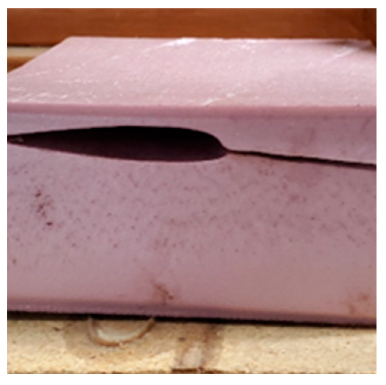
With the selection of Kevlar, there were two main construction methods to choose from: prepreg and wet layup. Prepreg is the use of a fiber material that has been pre-impregnated with epoxy and needs to cure at high temperatures. A wet layup is where a fiber composite material is molded to the contours of a desired shape and is then coated with epoxy that cures at room temperature. With the choice of a foam core for the various components, prepreg was not an option, as the foam core would not be able to withstand the temperatures of the autoclave necessary to cure the prepreg material. The method of wet layup for the wings used a negative mold that helped retain the correct shape. The foam negative mold for the horizontal tail can be seen in Figure 20.

Figure 20.
Foam mold with negative image removed.
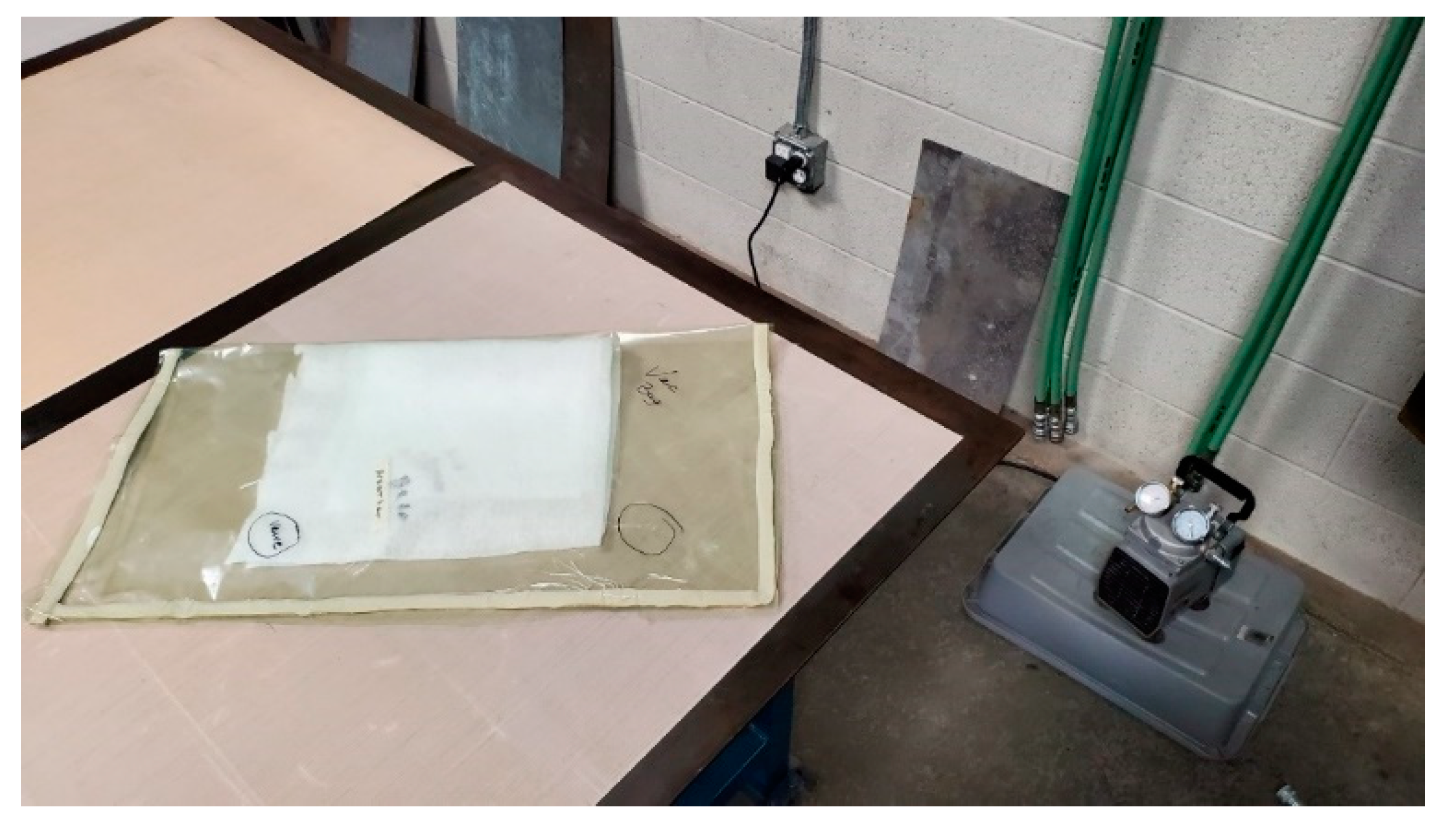
Weights were placed on top of the molds to apply pressure to the surfaces and press the fibers tightly to the foam core. This ensured a clean surface with minimal imperfections. Because the irregular shape of the fuselage prevented the use of negative molds, a vacuum bagging method was used. Multiple layers of Kevlar were wrapped around the fuselage and then coated with epoxy. The fuselage was then inserted into a vacuum bag and attached to a pump that applied uniform pressure to the entire model. The vacuum bagging setup can be seen in Figure 21.

Figure 21.
Vacuum bag and pump.
The vacuum bag method ensured even pressure over the entire model and resulted in a fuselage with a near-perfect Kevlar skin.
3.6.3. Current Selections and Future Improvements
The wing and control surfaces were manufactured using foam cores with a single-layer Kevlar shell. The fuselage was vacuum-bagged with several layers of Kevlar as its complex shape prevented the use of any foam molding. The Kevlar was bonded to the foam cores using a wet layup and negative images of the foam cores as well as a vacuum bag for an acceptable surface finish. Later models will utilize more rigid molds to rapidly vacuum-bag Kevlar shells without the need for foam or post-cure foam removal.
4. Flight Testing
To ensure the design would meet the design requirements, a variety of performance tests were conducted. The tests fell into four categories: Control Test, Wind Tunnel Test, Fixed Wing Flight, and Folding Wing Flight. The first test conducted was the Control Test.
4.1. Controlled Flight Model
For the Control Test, a dimensionally similar aircraft was constructed. It was designed to test the pitch, roll, and yaw capabilities of the design through flight testing. Three flights were conducted where the airplane was hand-launched and the pilot tested the aircraft. Through flight testing, the model achieved steady level flight, demonstrated adequate roll, pitch and yaw authority, and helped refine the control limiters of the aircraft.
4.2. Wind Tunnel Test
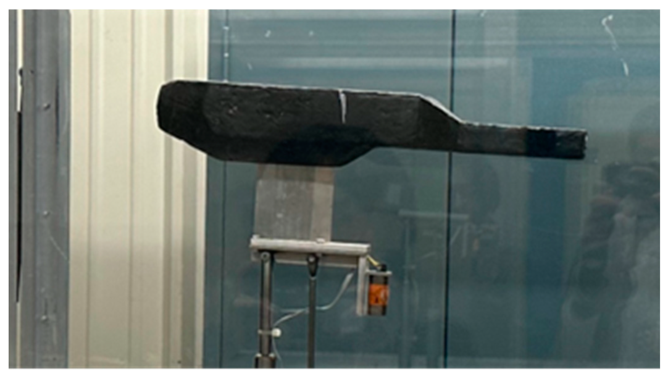
A Wind Tunnel Test of the full-scale fuselage was performed to confirm the drag predictions, evaluate the lifting characteristics of the fuselage, and analyze the flow separation. The wind tunnel testing was completed in the closed-circuit wind tunnel located at Embry-Riddle Aeronautical University’s Prescott Campus. The tunnel has a test section of 0.818 m by 1.143 m and can be operated at speeds up to 91.44 m/s. The wind tunnel is equipped with a six-component AEROLAB pyramidal balance. Figure 22 shows the model mounted in the wind tunnel.

Figure 22.
Wind tunnel model.
As seen in Figure 22, the model was coated with resin to mimic the outer surface finish of the final Kevlar layup model. Using the pyramidal balance to record the forces on the fuselage, seen attached to the bottom of the fuselage, wind tunnel testing was performed at stall (16.76 m/s), cruise (22.25 m/s), and max (36.58 m/s) velocity. From the analysis, it was found that the fuselage model produced drag that was higher than predicted during preliminary analysis. It was also found that the fuselage produced no lift and that the many sharp corners of the fuselage led to large flow separation. To combat these findings, a new fuselage with smooth lines was created, as seen in Figure 23.

Figure 23.
Fuselage evolution. (a) Side view of aircraft before wind tunnel testing; (b) side view of aircraft after wind tunnel testing.
As seen in Figure 23, the initial fuselage on the left had many sharp corners in comparison to the finalized fuselage on the right. These changes to the fuselage worked to reduce the flow separation and, thus, the pressure drag that resulted in the undesirable drag coefficients.
4.3. Fixed Wing Model
After the Wind Tunnel Test, a full-scale Kevlar fixed flight model was fabricated. This model was built with the wing and tail control surface locked and fixed in the unfolded position. With this aircraft, Fixed Wing Flights were conducted to determine whether the aircraft met the performance requirements. These flights included proof of steady level flight, 2 g pullout maneuver, and a lap around the field. Each of these requirements were validated via separate flights.
Internal UAV systems were chosen with the goal of maximizing success during a flight test. Standard remote controlled (RC) aircraft parts were used because of prior configuration knowledge and proven performance on aircraft of similar size. One configuration, used for fixed wing flight tests, has a standard receiver connected directly to the servos to allow direct pilot control. The transmitter enables the ailerons to be used as spoilers during launch from the canister to assist with unfolding the main wing.
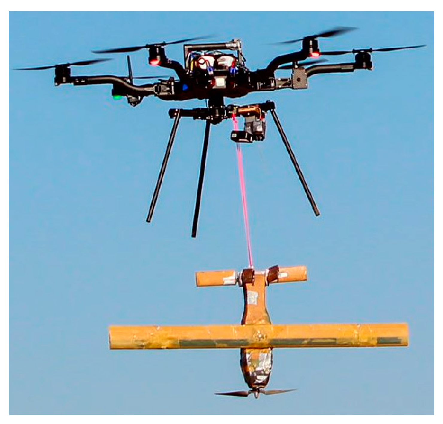
Over the course of two weeks, 17 flights were completed. The initial flights utilized a hand-launch system to propel the plane into the air. However, these initial flights were met with poor results, as the aircraft stalled upon launch. To simulate the speeds seen during the pullout maneuver, a car-assisted take-off was performed. This yielded excellent results, with steady level flight being proven. After these tests, the aircraft was deployed from altitude to perform the 2 g pullout and a lap around the field. To accomplish this procedure, the aircraft was carried with a hexcopter provided by Embry-Riddle Aeronautical University and released upon reaching the release altitude. A picture of the deployment system from the hexcopter can be seen in Figure 24.
Figure 24.
Hexcopter deployment system with Flying Fish.
For the two deployment tests, the hexcopter safely carried the fixed wing model from the ground to the release height, as seen in Figure 24. At the release altitude, the fixed wing model was dropped and cleanly separated from the hexcopter. The first deployment was completed with a release height of 198 m. The fixed wing model released with no issues and proceeded to perform the 2 g pullout maneuver. Once completed, the fixed wing model made a controlled landing. On the second drop test, the fixed wing model was carried to 152 m, the minimum predicted drop altitude, and released. With this test, the fixed wing model was not able to successfully perform the 2 g pullout maneuver and crashed. An analysis of the crash concluded that the total loss of the aircraft was due to a slow pilot response and a minimum drop altitude with no buffer.
4.4. Folding Wing Model
With the overall success of the fixed wing flight model, a folding wing flight model was created. This model utilized folding wing and tail control surfaces that were spring-activated and would lock into place. The same performance requirements as the fixed wing model were expected for this folding model, with the addition of a tube-launch deployment. A G-sized sonobuoy canister was created to test the fitting and deployment of the Flying Fish. Future work will include flight testing of the folding wing model.
From these flight tests, it has been determined that the Flying Fish is stable in flight and capable of performing its mission as designed.
5. Conclusions
The Flying Fish is a tube-launched UAV designed to expand the capabilities of manned aircraft performing search and reconnaissance missions. The Flying Fish, as designed, can fly a maximum of 111 km and 83 min while also performing a 2 g pullout and completing the ISR mission. The Flying Fish uses a variety of different folding mechanisms to fit within a G-size sonobuoy canister. The process of individual disciplinary design ensured that each part of the aircraft meets the relevant requirements. If desired, adding polyhedral would improve the roll and spiral stability and handling characteristics, reducing pilot fatigue during longer missions. Polyhedral could be added by modifying the main wing’s folding mechanism. Flight testing validated prior design work and proved that the fixed wing model of the Flying Fish was able to meet the performance requirements.
Author Contributions
Conceptualization, M.F., C.C.S., A.W., P.A.K., I.H., C.A., B.R. (Brandon Ragasa) and A.H.; methodology, M.F., C.C.S., A.W., P.A.K., I.H., C.A., B.R. (Brandon Ragasa) and A.H.; software, M.F., C.C.S., A.W., P.A.K., I.H., C.A., B.R. (Brandon Ragasa) and A.H.; validation, M.F., C.C.S., A.W., P.A.K., I.H., C.A., B.R. (Brandon Ragasa), A.H. and B.R. (Brian Roth); formal analysis, M.F., C.C.S., A.W., P.A.K., I.H., C.A., B.R. (Brandon Ragasa) and A.H.; investigation, M.F., B.R. (Brandon Ragasa) and I.H.; resources, B.R. (Brian Roth); data curation, M.F., C.C.S., A.W., P.A.K., I.H., C.A., B.R. (Brandon Ragasa) and A.H.; writing—original draft preparation, M.F., C.C.S., A.W., P.A.K., I.H., C.A., B.R. (Brandon Ragasa) and A.H.; writing—review and editing, M.F., C.C.S., A.W., P.A.K., I.H. and B.R. (Brian Roth); visualization, I.H. and C.A.; supervision, B.R. (Brian Roth); project administration, M.F., C.C.S. and B.R. (Brian Roth); funding acquisition, M.F., P.A.K. and B.R. (Brian Roth) All authors have read and agreed to the published version of the manuscript.
Funding
This research was funded by Embry-Riddle Aeronautical University, the Undergraduate Research Institute Ignite Grant, and the Raisbeck Engineering Design/Build/Test Endowment.
Data Availability Statement
Data available on request due to ownership restrictions. The data presented in this study are available on request from the corresponding authors. The data are not publicly available due to Embry-Riddle Aeronautical University owning the rights to the data.
Acknowledgments
Launch UAV would like to thank Johann Dorfling and Ken Bordignon for their technical expertise and advice throughout the course of this project. Without their input, the Flying Fish would never have come to fruition. Launch UAV would also like to thank Richard Magnum for the Technical Communication feedback received throughout the course of this project.
Conflicts of Interest
The authors declare no conflict of interest.
Nomenclature
| 2D | Two-Dimensional |
| 3D | Three-Dimensional |
| A | Ampere |
| AoA | Angle of Attack |
| AR | Aspect Ratio |
| b | Wingspan |
| B | Blaine Rawdon Parameter |
| Cd | 2-Dimensional Coefficient of Drag |
| CD | 3-Dimensional Coefficient of Drag |
| CHT | Horizontal Tail Volume Coefficient |
| Cl | 2-Dimensional Coefficient of Lift |
| CL | 3-Dimensional Coefficient of Lift |
| 3-Dimensional Maximum Coefficient of Lift | |
| 3-Dimensional Lift Curve Slope | |
| Coefficient of Roll Moment due to Sideslip | |
| Coefficient of Pitching Moment due to Angle of Attack | |
| Coefficient of Yaw Moment due to Sideslip | |
| CVT | Vertical Tail Volume Coefficient |
| CG | Center of Gravity |
| D | Drag |
| Env | Environment |
| ERAU | Embry-Riddle Aeronautical University |
| ESC | Electronic Speed Control |
| ft | Feet |
| ft/s | Feet Per Second |
| HT | Horizontal Tail |
| ISR | Intelligence, Surveillance, and Reconnaissance |
| KEAS | Knots Equivalent Airspeed |
| Kv | RPM Constant |
| Lh | Horizontal Tail Moment Arm |
| Lv | Vertical Tail Moment Arm |
| L/D | Lift-to-Drag Ratio |
| lb | Pounds |
| LiPo | Lithium Polymer |
| mAh | Milliamp-hour |
| mi | Mile |
| MSL | Mean Sea Level |
| NATO | North Atlantic Treaty Organization |
| PA | Power Available |
| PETG | Polyethylene Terephthalate Glycol |
| Per | Performance |
| Phy | Physical |
| PR | Power Required |
| rad | Radians |
| RC | Remote Controlled |
| RFP | Request for Proposal |
| ROC | Rate of Climb |
| RPM | Revolution Per Minute |
| S | Wing Area |
| s | Series |
| T/W | Thrust to Weight Ratio |
| Op | Operational |
| V | Volt |
| VT | Vertical Tail |
| UAV | Unmanned Aerial Vehicle |
| UIUC | University of Illinois Urbana-Champaign |
| W | Watt |
| W/S | Wing Loading |
| β | Sideslip angle |
| Υ | Dihedral |
References
- Brown, A. Sonobuoy Tube Launched UAV Navy STTR FY2004, N04-T004—Sonobuoy Tube Launched UAV. Available online: http://bit.ly/4b0WgHn (accessed on 25 November 2023).
- Department of Defense Announces Successful Micro-Drone Demonstration. U.S. Department of Defense, 9 January 2017. Available online: https://bit.ly/48HvsdH (accessed on 25 November 2023).
- Vogel, W.L. Numerical Flight Testing of a Tube-Launched Transformable Micro Air Vehicle, The Research Repository @ WVU. Available online: https://bit.ly/47MUDdw (accessed on 25 November 2023).
- Rakas, J.; Yin, H. Modeling the Impact of Equipment Outages on National Airspace System Operations. In Proceedings of the AIAA 5th Aviation, Technology, Integration, and Operations Conference, Arlington, VA, USA, 26–28 September 2005. [Google Scholar] [CrossRef]
- Henry, J.; Schwartz, D.; Soukup, M.; Altman, A. Design, construction, and testing of a folding-wing, tube-launched Micro Air Vehicle. In Proceedings of the 43rd AIAA Aerospace Sciences Meeting and Exhibit, Reno, Nevada, 10–13 January 2005. [Google Scholar] [CrossRef]
- Tube Launched UAS. Think Defence. 2023. Available online: https://bit.ly/3tUfC09 (accessed on 25 November 2023).
- Raytheon to Provide Army with Drones for Killing Other Unmanned Systems. National Defense Magazine. Available online: https://bit.ly/4b4GKKy (accessed on 25 November 2023).
- Ott, J.; Biezad, D. Design of a tube-launched UAV. In Proceedings of the AIAA 3rd ‘Unmanned Unlimited’ Technical Conference, Workshop and Exhibit, Chicago, IL, USA, 23 September 2004. [Google Scholar] [CrossRef]
- Raytheon Coyote. Available online: https://bit.ly/48HbxeU (accessed on 25 November 2023).
- NOAA’s Atlantic Oceanographic & Meteorological Laboratory. Available online: https://bit.ly/3u2airy (accessed on 25 November 2023).
- Outrider Unmanned Aircraft System. Airforce Technology. 2017. Available online: https://bit.ly/4b6fTh0 (accessed on 25 November 2023).
- Valpolini, P. Switchblade 600, the New Medium Range Loitering Munition, EDR Magazine. 2023. Available online: https://bit.ly/3u27Wce (accessed on 25 November 2023).
- Aerovironment. Available online: https://bit.ly/4949tND (accessed on 25 November 2023).
- Tube Launched UAV. Design Show 2019. Available online: https://bit.ly/429guuo (accessed on 25 November 2023).
- AeroVironment, Inc. Switchblade. Available online: https://bit.ly/4b5Qrs8 (accessed on 28 November 2023).
- Antoine, N.E.; Kroo, I.M. A framework for aircraft conceptual design and Environmental Performance Studies. In Proceedings of the 10th AIAA/ISSMO Multidisciplinary Analysis and Optimization Conference, Albany, NY, USA, 30 August–1 September 2004. [Google Scholar] [CrossRef]
- Brandt, S.A. Introduction to Aeronautics: A design Perspective; American Institute of Aeronautics and Astronautics, Inc.: Reston, VA, USA, 2015. [Google Scholar] [CrossRef]
- Raymer, D.P. Aircraft Design: A Conceptual Approach; American Institute of Aeronautics and Astronautics, Inc.: Washington, DC, USA, 1992. [Google Scholar] [CrossRef]
- Napolitano, M.R. Aircraft Dynamics: From Modeling to Simulation; J. Wiley: Hoboken, NJ, USA, 2012. Available online: https://lccn.loc.gov/2011029934 (accessed on 23 January 2024).
- Brandt, J.B.; Deters, R.W.; Ananda, G.K.; Dantsker, O.D.; Selig, M.S. UIUC Propeller Data Site. Available online: https://bit.ly/3SsIWEj (accessed on 25 November 2023).
- Performance Data. APC Propellers. 2023. Available online: https://bit.ly/3SumjQ3 (accessed on 25 November 2023).
- Selig, M.S.; Donovan, J.F.; Fraser, D.B. Airfoils at Low Speeds; H. A. Stokley: Virginia Beach, VA, USA, 1989; Available online: https://bit.ly/3OdcnYw (accessed on 23 January 2024).
- Dantsker, O.; Vahora, M. Comparison of aerodynamic characterization methods for design of unmanned aerial vehicles. In Proceedings of the 2018 AIAA Aerospace Sciences Meeting, Kissimmee, FL, USA, 8–12 January 2018; p. 272. [Google Scholar] [CrossRef]
- Shen, J.; Su, Y.; Liang, Q.; Zhu, X. Calculation and Identification of the Aerodynamic Parameters for Small-Scaled Fixed-Wing UAVs. Sensors 2018, 18, 206. [Google Scholar] [CrossRef] [PubMed]
- Light Unmanned Aircraft Systems Airworthiness Requirements. 2014. Available online: https://bit.ly/3SvvsI5 (accessed on 25 November 2023).
Disclaimer/Publisher’s Note: The statements, opinions and data contained in all publications are solely those of the individual author(s) and contributor(s) and not of MDPI and/or the editor(s). MDPI and/or the editor(s) disclaim responsibility for any injury to people or property resulting from any ideas, methods, instructions or products referred to in the content. |
© 2024 by the authors. Licensee MDPI, Basel, Switzerland. This article is an open access article distributed under the terms and conditions of the Creative Commons Attribution (CC BY) license (https://creativecommons.org/licenses/by/4.0/).

