Article

Dynamic Encircling Cooperative Guidance for Intercepting Superior Target with Overload, Impact Angle and Simultaneous Time Constraints

1
School of Astronautics, Northwestern Polytechnical University, Xi’an 710072, China
2
Shaanxi Aerospace Flight Vehicle Design Key Laboratory, Northwestern Polytechnical University, Xi’an 710072, China
*
Author to whom correspondence should be addressed.
Aerospace 2024, 11(5), 375; https://doi.org/10.3390/aerospace11050375
Submission received: 23 April 2024 / Revised: 6 May 2024 / Accepted: 7 May 2024 / Published: 8 May 2024

Abstract

:
This paper proposes a dynamic encircling cooperative guidance (DECG) law to enable multiple interceptors to cooperatively intercept a superior target, considering low velocity, limited overload, impact angle and simultaneous arrival constraints. First, the feasible escaping area of the target is analyzed and a dynamic encircling strategy for the target is established. This strategy efficiently provides virtual escaping points, allowing interceptors to dynamically encircle the target without excessive energy consumption, ultimately leading to a successful interception. Second, to enhance the physical feasibility of the kinematic equations governing the interaction between interceptors and target at the virtual escaping points, the independent variable is substituted and the kinematic equations are remodeled. Convex optimization is employed to address the multi-constraint optimal guidance problem for each interceptor, thereby facilitating simultaneous interception. Compared with the existing guidance laws, DECG has a more practical and feasible cooperative strategy, is able to handle more constraints including the interceptor’s own constraints and cooperative constraints, and does not rely on the precise calculation of explicit remaining flight time in the guidance law implementation. Lastly, the effectiveness, superiority and robustness of the DECG law are evaluated through a series of numerical simulations, and its performance is compared with that of the cooperative proportional navigation guidance law (CPNG).

1. Introduction

The threat to fighter aircraft in the air is often a single superior target; therefore, the traditional self-protection methods such as maneuvering evasion, dropping decoys or launching a single inferior interceptor for interception are no longer sufficient to address such threats, so it has become particularly important to study the strategies and control methods for cooperative interception with multiple inferior interceptors. A number of studies have explored this issue at different levels.
Among the studies addressing the fighter self-protection problem, a portion of the research explores how a fighter and a single inferior interceptor can cooperate and game the interception of a threatening target, while some studies explore how multiple interceptors can cooperate to intercept a target, including the cooperation strategy and control methods. Garcia et al. laid the groundwork by introducing the three-body model, providing initial insights into this problem [1]. Building upon this conceptual foundation, subsequent research contributions have further explored various facets of cooperative interception. Garcia et al. established a confrontation model involving the target, aircraft and interceptor, effectively transforming the interception problem into a pursuit and evasion problem [1]. Subsequent contributions extended this framework, with [2] pioneering the application of the differential game method to address the problem. However, Von Moll et al. delved into pursuit and evasion game problems involving multiple entities and utilized the differential game approach, noting that the differential games problem may lead to optimal outcomes for both sides, which might not align with the dynamics of the cooperative interception problem [3,4,5,6]. Notably, Yan et al. respectively derived analytical guidance laws for aircraft and interceptors based on the relationship between remaining flight time and miss distance, meeting specific performance indicators [7,8,9]. Sinha investigated cooperative guidance laws within time constraints to achieve salvo attack, but the method was tailored for stationary targets [10]. Departing from controlling remaining flight time, the modified model predictive control (MPC) is adopted to make state variables converge over time, aiming for the simultaneous interception [11]. In a three-dimensional scenario, the model predictive static programming (MPSP) method is used to explore guidance laws incorporating remaining flight time and attack angle constraints [12]. Moreover, cooperative guidance laws incorporating both attack angle and line-of-sight constraints were separately focused, with limited-time convergence guidance laws proposed [13,14]. Guidance laws grounded in line of sight were applied to address this scenario, emphasizing the geometric concept of line of sight [15,16]. Addressing the interception of highly maneuverable attacker by less maneuverable interceptors, the concept of acceleration coverage was employed [17,18]. Similarly, for the coverage-based cooperation, the flight path angle controlling method was adopted for practical effectiveness [19]. Yan et al. investigated using an analysis of interceptors’ reachability, extending it to cover the defender’s escaping area [20,21]. Exploring the leader–follower method within the cooperative protection, it was applied it to cluster research [22]. Shifting towards advanced methodologies, Chen et al. investigated the application of deep reinforcement learning and other machine learning techniques in interception [23,24,25,26], showcasing the research potential of machine learning in this domain, though underscoring the need for enhanced generalization. Computational guidance, such as the convex optimization method, is used to control the trajectory of interceptors, which can satisfy complex constraints [27]. Finally, Zhou et al. conducted an analysis of confrontation outcomes when interceptors and the target employed different guidance laws, deriving launch area and command accelerations for interceptors under various conditions [28].
These collective contributions represent a substantial advancement in the comprehension of cooperative interception in the aircraft’s self-protection, addressing its diverse challenges across theoretical frameworks, practical implementations, and machine learning methodologies. Nevertheless, it is imperative to emphasize that the majority of the prevailing laws of cooperative orientation present three recurrent limitations: (1) Insufficient strategic practicality: Numerous studies fail to formulate a practical strategy that takes into account the likelihood that interceptors will require substantial maneuvers, leading to notable energy depletion [13,14,15,16]. (2) Insufficient ability to manage constraints: Cooperative interception is a multi-constraint problem, with constraints not only on the individual interceptor but also on the cooperative constraints of the group of interceptors. Most of the current research can only deal with some of the constraints [2,7,16,29], the fundamental reason for which being that cooperative constraints are often interrelated with cooperative strategy, and a reasonable cooperative strategy can only take into account maneuverable cooperative constraints. In addition, the approach to the cooperation problem will also determine whether some constraints can be handled or not; for example, it is difficult to handle the constraints of the acceleration process by the proportional guidance-based cooperation method. This oversight becomes especially critical when considering the potential limitations of interceptor maneuverability. (3) Dependence on the precise explicit calculation of the “departure time”: Some studies that considered the simultaneous arrival time constraints have relied on the flight remaining explicit t g o time calculations [7,10], but since it is difficult to calculate t g o precisely during the guidance law design process, as well as during actual interceptor flight, it is necessary to consider the realization of simultaneous arrival time constraints by other variables.
Motivated by the aforementioned research, this paper studied the fighter aircraft self-protection problem with multiple interceptors to cooperatively and simultaneously intercept the target to safeguard the fighter aircraft, considering the interceptor’s lower velocity, limited overload and impact angle constraints. To address the above problem, the DECG guidance law is proposed in this work, and its main contributions are as follows below:
(1)
Different from the approaches outlined in refs. [13,14,15,16], the introduced DECG law is based on a feasible dynamic encircling strategy, considering the physical ability of all flight vehicles involved, which can offer a more practical cooperative strategy for the cooperative guidance and ensure the precise interception of the target by at least one interceptor being restricted to low velocity, limited maneuverability and desired impact angle. Noteworthy is the low ability of a single interceptor; the DECG can thereby leverage the group advantage of interceptors and significantly enhance their overall interception performance.
(2)
Compared with refs. [11,23], the DECG law employs successive convex optimization to address the guidance problem, which is also tightly coupled with the cooperative strategy. This approach offers improved constraints processing capabilities, control precision and also has good computational efficiency in comparison to existing methodologies. Compared with refs. [30], the proposed DECG improves the time calculation strategy and adopts a more precise solving method.
(3)
Compared with refs. [10,22,31], this paper remodels the interception mathematical model using the independent variable of distance, a parameter directly measured by the interceptor’s sensor, thereby enhancing practicality. Furthermore, the chosen independent variable exhibits a monotonically decreasing trend, underscoring the rationale and physical feasibility of the newly proposed interception model. This modification no longer requires the precise calculation of explicit t g o and also aligns the interception model more closely with real-world scenarios, which brings convenience to simultaneous control and realization.
The subsequent sections of this paper are structured as follows: Section 2 addresses the problem of multiple interceptors intercepting a superior target in the planar scenario and outlines the design of the DECG law. Numerical simulations are presented in Section 3, and conclusions are drawn in Section 4.

2. Dynamic Encircling Cooperative Guidance Law Design

In this section, the cooperative interception problem is established and the development of the DECG is presented to address the cooperative interception challenges within the fighter aircraft self-protection scenario. The DECG consists of two main components: a dynamic encircling interception strategy for the target by the interceptors, and a solving method based on successive convex optimization. Subsequent sections provide a detailed exposition of the DECG methodology.

2.1. Problem Formulation

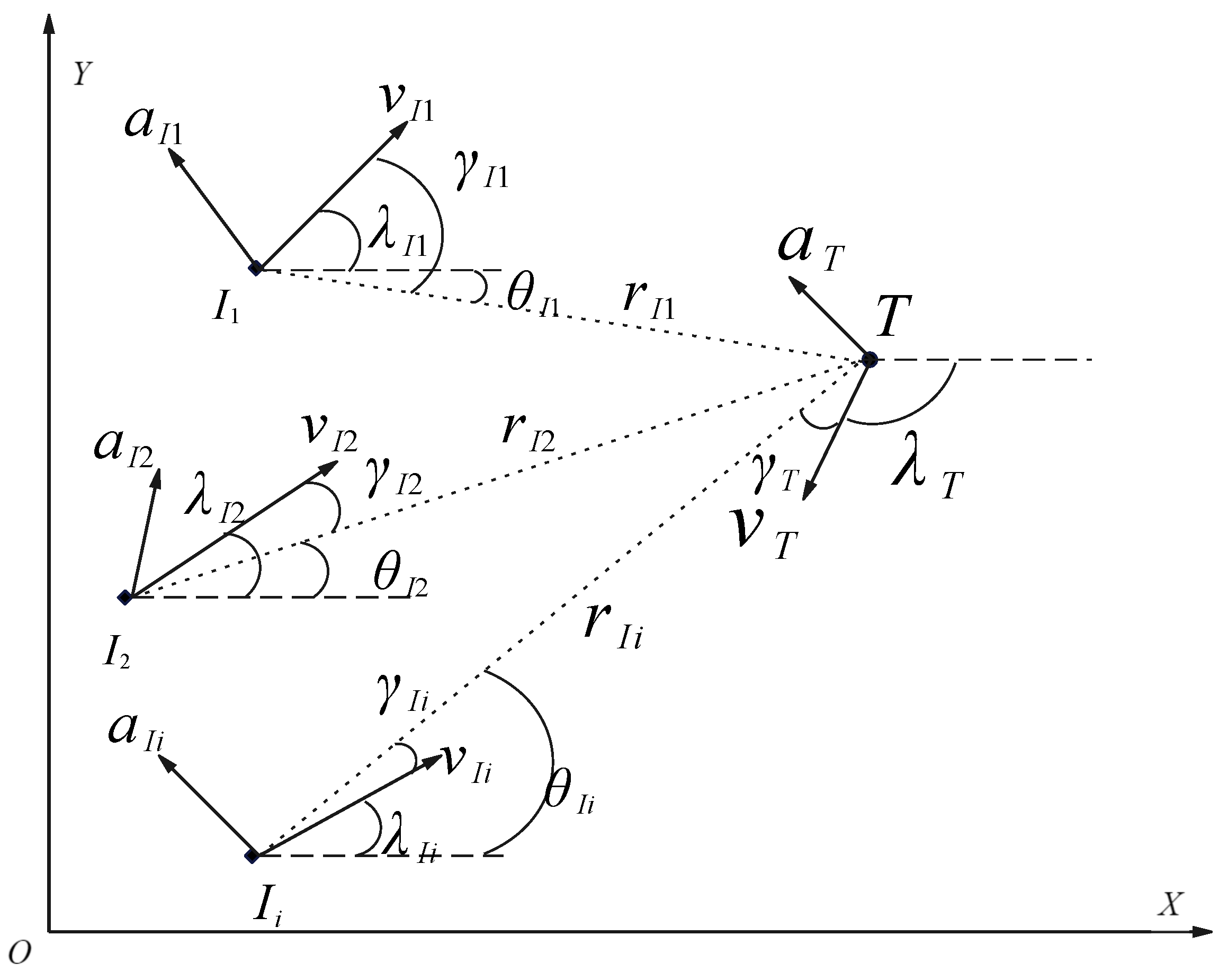
This paper focus on cooperative guidance strategy for intercepting high-speed and strongly maneuverable target within the planar scenario. The relative geometry between interceptors and the target is illustrated in Figure 1. It is assumed that interceptors are launched simultaneously. In the scenario of cooperative guidance for multiple interceptors, this paper adopts some assumptions, as follows:
Assumption 1.
Both interceptors and the target are treated as ideal mass points, ignoring their shapes, the influence of the rotation of the earth, and the interference of the external environment.
Assumption 2.
Both the interceptors and the target keep maneuvering at a constant velocity.
Figure 1. Multiple interceptors intercepting a target.
Aerospace 11 00375 g001
where ( X , O , Y ) denotes the inertial coordination system; the subscripts I i and T represent the i t h interceptor and target, respectively. r is the relative range, θ is the line-of-sight (LOS) angle, γ is the look angle, λ is the flight path angle, V is the velocity and a is the acceleration.
As can be seen from Figure 1, when multiple interceptors intercept a moving target, the velocity and acceleration of the moving target need to be considered. At this time, the relative kinematic equations between the interceptors and the target are shown in Equation (1). Since the acceleration and velocity of the target are changing all the time, it is difficult to predict the interception point, so it is necessary to consider and design a suitable cooperative strategy, and utilize the number advantage of the interceptors to cover the possible escaping zone of the target in order to realize the purpose of interception.
d r ˙ I i = V T cos γ T V I i cos γ I i r I i θ ˙ I i = V T sin γ T V I i sin γ I i λ ˙ I i = a I i / V I i λ ˙ T = a T / V T γ I i = λ I i θ I i γ T = λ T θ T

2.2. Dynamic Encircling Strategy and Escaping Points Design

In the fighter aircraft self-protection scenario involving a target attacking the aircraft and an interceptor intercepting the target, particularly in the terminal phase of interception, the target will maneuver to attack the aircraft. During the maneuvering process, the target’s maneuvering area will form a reachable zone, and the maximum reachable zone is characterized by a fixed overload, transitioning from a T m a x to a T m a x over a finite time. For the interceptors, the target’s reachable zone transforms into its escape area. If the maximum escape area can be covered by the interceptors, then the effective interception can be guaranteed, which in the key of the cooperative interception strategy. The escape area of the target is delineated in Figure 2a,b, and the difference between them is how long the escaping time lasts. In Figure 2a, the target’s escaping time is relatively short, not enough to form a whole 1/4 arc; conversely, the escaping time in Figure 2b is not less than the time it takes to form the 1/4 arc, so the escape area can be considered as a combined escape area formed by the 1/4 arc and the length of the escaping straight line. Here, R represents the minimum turning radius of the target, while L represents the distance traversed by the target along a straight path following a 90 turn. In realistic combat scenarios, the target’s decision to turn either left or right is oriented towards maximizing its lateral distance perpendicular to the line of sight.
In this study, the target’s escape area is discretized into n sub-escape areas, where n represents the number of interceptors involved. Each sub-escape area is centered around a virtual target T v i , ( i = 1 , 2 , , n ) . The cooperative guidance aims to ensure that the reachable sets of these n interceptors effectively cover their respective sub-escape areas. Figure 3 shows the how the dynamic encircling guidance strategy works combined with the definition of the target’s escaping area above. H denotes the escape area formed by T v i within the planar X O Y scenario; T 0 to T i represent the positions reached by the target in different escape directions, while I 0 to I i are the corresponding interceptors. As depicted in Figure 3, the dynamic encircling guidance strategy is structured as follows: (1) Assume the escape distance H is divided into n sub-intervals, with each spanning H / n . The midpoint of each sub-interval, denoted as T v i , signifies the predicted interception point. Each interceptor is assigned the responsibility of covering one of these sub-escape intervals. (2) As the remaining flight time diminishes, the virtual predicted interception points T i gradually converge towards the actual position of the target. (3) Eventually, interceptors progressively approach the real target. This sequential process encapsulates the dynamic encircling and convergence of the interceptors toward the target, culminating in the successful interception of the target. The dynamic encircling strategy, devoid of pre-set LOS angle constraints, is realized by setting multiple virtual targets. These virtual targets are dynamically computed based on the movements of the real target, progressively converging upon the real target from various directions.
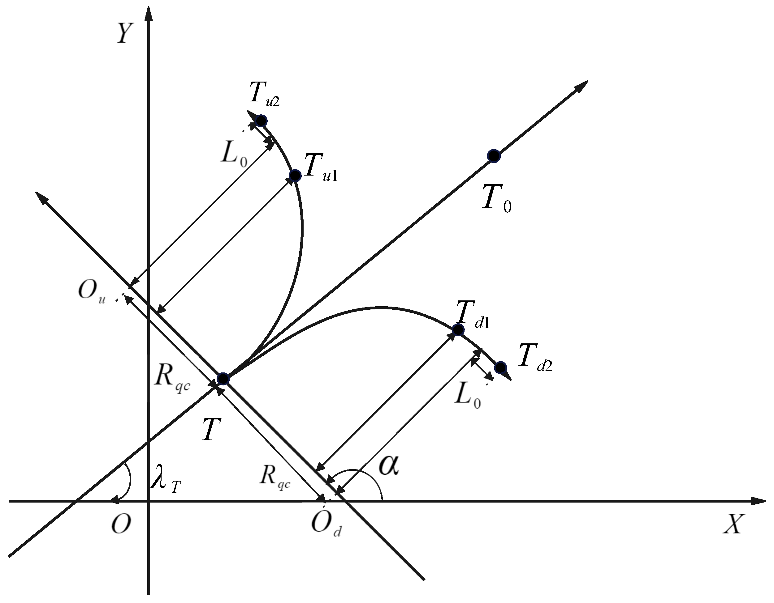
Given that each interceptor is tasked with dynamically intercepting its corresponding predicted interception point and facilitating the process of dynamic cooperative encircling, it becomes imperative to initially compute the virtual escape points of the target, denoted as the predicted interception points T v i . The virtual escape points geometry is depicted in Figure 4, T u 1 and T u 2 are the points in the upper part of the corresponding escape area in Figure 4, T d 1 and T d 2 are the corresponding points in the lower area. When the target T escapes, the time required to form a 1/4 arc trajectory is t q c , the arc radius is R q c , and the escaping straight line distance is L 0 . In the absence of any maneuver, when the target escapes, it reaches the escaping point T 0 after the escaping time t p , representing the predicted interception point ( x 0 , y 0 ) . Utilizing the geometric relationship inherent in the target’s escaping area, the coordinates of the respective predicted interception points can be calculated as follows:
x 0 = V T t p c o s λ T + x T y 0 = V T t p s i n λ T + y T
where λ T is the flight path angle, ( x T , y T ) is the initial position of the target, V T is the velocity of the target.
When t p t q c , according to the geometric relationship, the two predicted escaping points of the target can be obtained as ( x u 1 , y u 1 ) and ( x d 1 , y d 1 ) shown in Figure 4, the coordination calculation equations are:
x u 1 = R q c [ 1 c o s α ] s i n λ T + R q c s i n α c o s λ T + x T y u 1 = R q c [ 1 c o s α ] c o s λ T + R q c s i n α s i n λ T + y T
where α is a geometric angle in the escape area.
x d 1 = R q c [ 1 c o s α ] s i n λ T + R q c s i n α c o s λ T + x T y d 1 = R q c [ 1 c o s α ] c o s λ T + R q c s i n α s i n λ T + y T
When t p > t q c , according to the geometric relationship, the two predicted escaping points of target can be obtained as ( x u 2 , y u 2 ) and ( x d 2 , y d 2 ) shown in Figure 4, the coordination calculation equations are:
x u 2 = ( R q c + L 0 ) s i n λ T + R q c c o s λ T + x T y u 2 = ( R q c + L 0 ) c o s λ T + R q c s i n λ T + y T
x d 2 = ( R q c + L 0 ) s i n λ T + R q c c o s λ T + x T y d 2 = ( R q c + L 0 ) c o s λ T + R q c s i n λ T + y T
In accordance with the aforementioned geometric relationship and calculation equations, presuming the presence of n interceptors tasked with dynamically encircling and intercepting the target, the coordinates of the i t h virtual predicted interception points can be calculated as follows:
When t p t q c
x v i = n 2 i + 1 n ( R q c + L 0 ) s i n λ T + R q c c o s λ T + x T y v i = n 2 i + 1 n ( R q c + L 0 ) c o s λ T + R q c s i n λ T + y T
When t p > t q c
x v i = n 2 i + 1 n R q c [ 1 c o s α ] s i n λ T + R q c s i n α c o s λ T + x T y v i = n 2 i + 1 n R q c [ 1 c o s α ] c o s λ T + R q c s i n α s i n λ T + y T
The R q c represents the radius of the escaping circle formed when the target adopts the maximum acceleration to escape, and it is calculated as follows:
R q c = V T 2 / a m a x
The time required for a target to form a 1/4 escape arc is t q c , and it is calculated as follows:
t q c = π R q c / 2 V T
The geometric angle α can be calculated as follows:
α = π t p / 2 t q c
The term L 0 can be calculated as follows:
L 0 = V T ( t p t q c )
The escaping time t p determines the value of the arc radius and the straight line distance. However, in scenarios where the distance between the target and the interceptors is considerable, aggressive maneuvers by the interceptors can result in significant energy wastage. To mitigate this, when the distance is substantial, it becomes essential to design a rational t p . This term ensures that the interceptors refrain from aggressive maneuvers, conserving energy for subsequent precise interception. Consequently, the term t p can be strategically designed as follows:
t p ( t ) = t g o t p max t < t s t g o 0 t δ t t s t t e 0.1 t g o t > t e
The parameters t p max and δ t are the specified parameters, t e and t s can be calculated as follows:
t s = t g o 0 δ t t p max t e = t g o 0 δ t
where t g o is the remaining flight time of the target.
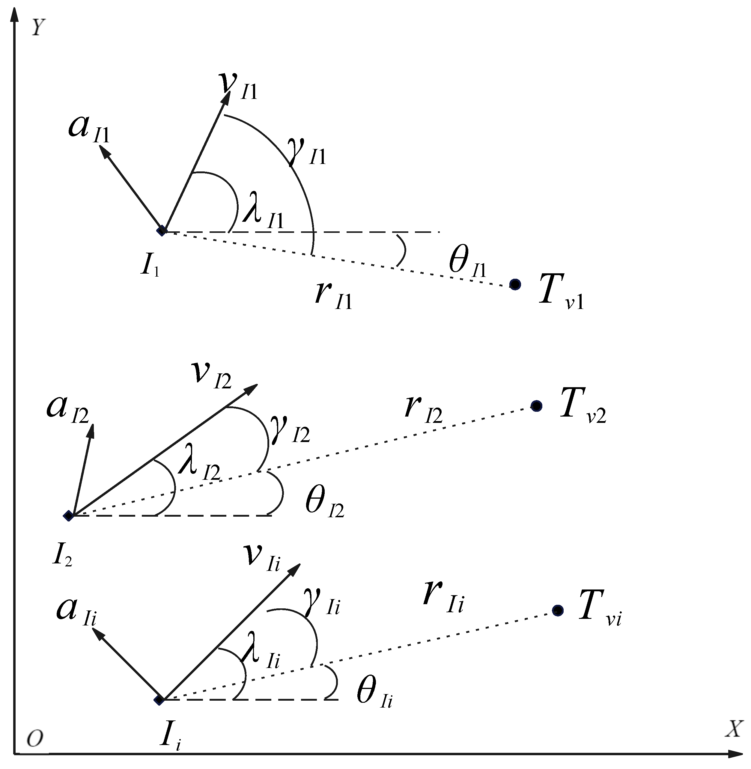
After the dynamic encircling (DE) strategy, the problem of multiple interceptors intercepting a moving target is transformed into the problem of multiple interceptors intercepting the corresponding virtual ‘fixed’ target points, and the DE strategy not only simplifies the original interception problem, but also makes the cooperative constraints easier to address. The transformed problem scenario is shown in Figure 5 and the kinematics between an interceptor and a virtual target point are shown in Equation (15):
r ˙ I i = V I i c o s θ I i r I i θ ˙ I i = V I i s i n θ I i γ ˙ I i = λ ˙ I i θ ˙ I i λ ˙ I i = a I i / V I i
where ( X , O , Y ) denotes the inertial coordination system; I i denotes the i t h interceptor; T v i denotes the i t h virtual target at the predicted escaping point, which is the position that the target may reach when escaping; and a and v denote the acceleration and speed, respectively. γ , λ and θ denote the look angle, the flight path angle and LOS angle, respectively; r denotes the relative range between an interceptor and a target.
At this point, the problem of multiple interceptors cooperating to intercept a target can be summarized as the following guidance problem, which is to find the acceleration control input while satisfying the kinematics, terminal angle constraints, acceleration path constraints, and simultaneous arrival time constraints needed for the cooperative dynamic encircling.
  • obj.
f i n d   a I i
  • s.t.
E q u a t i o n ( 15 ) θ i ( t f ) = θ i * | a i ( t ) | a i m a x t f i = t f j i , j n
where i and j represent the interceptors, θ i * is the desired terminal LOS angle, a i m a x is the maximum acceleration, t f is the final interception time.

2.3. Simultaneous Interception Using Convex Optimization

In order to facilitate the practical engineering application, most of the interceptors adopt the proportional guidance law. In order to make the results of the study more relevant to practical applications, this paper takes the proportional guidance law as the basis and adopts the convex optimization method to obtain the proportionality coefficient that satisfies the cooperative objective. Assuming a proportional guidance law for the interceptor, it is expressed as follows:
d λ i d t = N i ( t ) d θ i d t
The kinematic equations can be modified as follows:
d r i d t = V i ( t ) c o s γ i ( t ) r ( t ) d θ i d t = V i ( t ) s i n γ i ( t ) d γ i ( t ) d t = [ ( N i ( t ) 1 ) V i ( t ) s i n γ i ( t ) ] / r i ( t )
The acceleration of the interceptor can be calculated as follows:
a i = V i d γ i ( t ) d t = V i N i ( t ) d θ i d t = N i ( t ) ( V i ( t ) 2 s i n γ i ( t ) ) r i ( t )
Building on the previously kinematics and acceleration expressions, it is evident that identifying an appropriate proportional guidance coefficient can effectively address the kinematics while adhering to acceleration constraints. The states of the interceptor changes continuously during its flight, the proportional guidance coefficient also needs dynamic adjustment for achieving the desired objectives. To address this dynamic requirement, this paper adopts an optimization approach to determine the most effective proportional guidance coefficients for the interceptor. Initially, the optimization problem P 0 is formulated based on the design requirements as follows:
  • obj.
f i n d   u i = N i ( t )
m i n   J i ( t ) = t t 0 t t f a i 2 ( t ) d t
  • s.t.
E q u a t i o n ( 19 ) θ i ( t f ) = θ i * | a i ( t ) | a i m a x t f ( i ) = t f ( j ) i , j n
Within the aforementioned constraints, the acceleration constraint serves to satisfy the limited overload for the interceptors, while the LOS angle constraint works to enhance the overall interception effectiveness. To facilitate the cooperative dynamic encircling by multiple interceptors, it is imperative to control the remaining flight time of each interceptor, ensuring simultaneous interception. Flight time constraints need to be incorporated for this purpose:
t g o i ( t f ) = t *
where t * is the expected cooperative time. The time control strategy for the cooperative interception is illustrated in Figure 6, and the strategy works as follows: (1) by solving problem P 0 , the optimal interception time of each interceptor can be calculated; (2) obtain the cooperative and simultaneous interception time t * of the interceptors through the principle of average distribution; (3) use the convex optimization method to solve problem P 2 based on t * to obtain the cooperative interception proportional coefficients for the interceptors; (4) by substituting the proportional coefficients that satisfy the constraints into the kinematic equations of the interceptors, the cooperative interception trajectories of the interceptors can be produced.
The cooperative time strategy underscores the importance of precise control over flight time t g o ; however, the accurate calculation of t g o is often a challenge. Existing methods for calculating t g o often rely on the assumption that the vehicles’ velocity remains constant throughout the flight, an assumption that may not hold true as the velocity will change. Consequently, it is reasonable to consider treating the independent variable, time t, as a state variable and employing optimization techniques to iteratively determine the accurate value. Furthermore, since the flight distance r can be precisely measured by interceptors and adheres to a monotonically decreasing pattern, aligning with the principles of kinematics, it can also be treated as an independent variable. By redefining t as a state variable and r as an independent variable, Equation (19) can be modified as follows:
d t i d r i = 1 / ( d r i d t i ) = 1 V i c o s γ i r i d θ i d r i = r i d θ i d r i d t i d r i = t a n γ i r i d γ i d r i = r i d γ i d r i d t i d r i = ( u i 1 ) t a n γ i
To eliminate the trigonometric functions in Equation (25) and to facilitate the convexification process, let ϵ = t a n γ , to obtain the following equations:
1 c o s γ i = 1 + t a n γ i 2 ( t a n γ i ) = 1 c o s γ i 2 = s i n γ i 2
Then Equation (25) can be simplified as follows:
d t i d r i = 1 + t a n γ i 2 / V i = 1 + ϵ i 2 / V i r i d θ i d r i = ϵ i r i d ϵ i d r i = r i d ϵ i d γ i d γ i d r i = 1 c o s γ 2 ( u i 1 ) t a n γ i = ϵ i ( 1 ϵ i 2 ) + ϵ i ( 1 + ϵ i 2 ) u i
Following the aforementioned procedure, the optimization problem P 0 can be modified to P 1 :
  • obj.
m i n   J i ( r i ) = t t 0 t t f ( ( N i ( t ) V i ( t ) 2 s i n γ i ( t ) r i ( t ) ) ) 2 d t d t d r = r r 0 r r f V i 3 ϵ i 2 u i 2 r i 2 1 + ϵ i 2 d r
  • s.t.
E q u a t i o n ( 27 ) θ i ( r f ) = θ i * | a i ( r i ) | a i m a x
Meanwhile, the cooperative time constraint is modified as follows:
t g o , i ( r f ) = t *
Define the state variable x i ( k ) = [ t i ( k ) θ i ( k ) ϵ i ( k ) ] , the kinematics of the interceptor are modified as follows:
r i d x i d r i = f ( x i ) + g ( x i ) u i
f ( x i ) = r i 1 + τ i 2 / V i ϵ i ϵ i ( 1 + ϵ i 2 ) g ( x i ) = 0 0 ϵ i ( 1 + ϵ i 2 )
The state space equation is as follows:
r i d x i d r i = A ( x i k ) + B ( x i k ) u i + Δ ( x i k )
Where the coefficients matrix can be calculated by the following Equation (34):
A ( x i k ) = f x i ( x i k ) + g x i ( x i k ) u i k B ( x i k ) = g ( x i k ) Δ ( x i k ) = f ( x i k ) A ( x i k )
To improve the convergence, precision and computational efficiency of optimization problem P 1 , convex optimization is adopted. Non-convex elements within P 1 are solely present in the performance objectives, necessitating the convexification of these objectives in P 1 . For performance metrics structured as J = t t 0 t t f a 2 d t , the following transforming methods in Equation (35) can be applied to convexify them:
J = t t 0 t t f ζ d t a 2 ζ
The objective function Equation (28) can be expressed as a linear function after discretization. This transformation method introduces a new inequality constraint Equation (35), but Equation (35) is a second-order cone constraint that is convex and thus retains convexity. Therefore, the non-convex terms in the performance index are addressed through convexification using the equivalent transformations outlined above, as described in the following Equation (36):
J i = r i 0 r i f a i 2 d r i = r i 0 r i f V i 3 ϵ i 2 u i 2 r i 2 1 + ϵ i 2 d r i
Let J i = r i 0 r i f ξ i d r i , where ξ is the transformation variable and satisfies the following equation:
V i 3 ϵ i 2 u i 2 r i 2 1 + ϵ i 2 ξ i
The nonlinear term on the left-hand side of Equation (37) necessitates a further convexification process. Define the variable ς , which satisfies the following equation:
ς ( k ) = ( r i ( k ) ) 2 1 + ( ϵ i ( k ) ) 2 ( V i ( k ) ) 3 ( ϵ i ( k ) ) 2
Then Equation (37) can be modified as follows:
( u i 2 ) ( k ) ξ i ( k ) ς i ( k )
Finally, Equation (28) is transformed to a second-order cone constraint, which is convex and enables its solution through convex optimization methods.
With a variety of lossy convexification techniques applied to tackle optimization problem P 1 , in order to attain an optimal solution closely approximating the original problem, it becomes imperative to utilize successive convex optimization methods for iteratively optimizing P 1 . Consequently, the iteration termination condition needs to be defined as follows:
| x i ( k ) x i ( k 1 ) | δ i
where δ is the control parameter to stop the iteration.
Finally, the original nonlinear optimization problem P 0 is transformed into a convex optimization problem P 2 in the form of second-order cone programming (SOCP) with r as the independent variable and t turned into a state variable, and the optimization problem P 2 is formulated as follows:
  • obj.
m i n   J i = r i 0 r i f ς i + ω ( t g o , i t * ) d r i
  • s.t.
E q u a t i o n s ( 30 ) a n d ( 33 ) E q u a t i o n s ( 38 40 ) θ i ( r f ) = θ i * | a i ( r i ) | a i m a x
where the ω is the coefficient to adjust the cooperative time in the objective function, in this work, its value is 10 2 .
The calculation process of the dynamic encircling cooperative guidance for the interceptors is illustrated in Figure 7. The DECG calculation process is as follows: (1) obtain the virtual target positions by calculating the DE strategy and establish the problem P 0 ; (2) reconstruct the problem P 0 to obtain the new problem P 1 through the substitution of independent variables; (3) use the convex optimization method to process the problem P 1 to obtain the problem P 2 with convex form; (4) solve the problem P 2 to obtain the control input and flight trajectory of the interceptors and judge whether the interception is successful or not; if it is unsuccessful, then continue the above guidance calculation.

3. Numerical Simulation

In this section, the effectiveness of the DECG law is evaluated through a series of numerical simulations. Throughout the simulations, it is assumed that multiple interceptors endeavor to intercept the target from the same initial relative range, with the target positioned at the center of the field of view (FOV) of the interceptors. Additionally, the simulations disregard both the angle of attack and sideslip angle of the interceptors, considering the velocity direction of the interceptors to be coincident with their symmetry axis. The initial conditions for the interceptors, target and fighter aircraft are detailed in Table 1, with the gravitational coefficient g = 9.81 m / s 2 . In this work, the number of interceptors is n = 3 .
The computational environment is configured as follows: the CPU computing frequency is 2.6 Ghz, the programming platform is matlab 2023 b, and the convex optimization solver is ECOS. The average time consumed to compute the control input of the DECG guidance law in Cases 1, 2, and 3 is less than 10 ms, and the average time consumed to compute the robustness verification calculation in Case 4 is less than 20 ms. The computational time consumed can be further reduced when the programming language is changed to C. Therefore, the computational efficiency of DECG has certain value for practical application.

3.1. Case 1: Fighter Aircraft Makes No Maneuvers

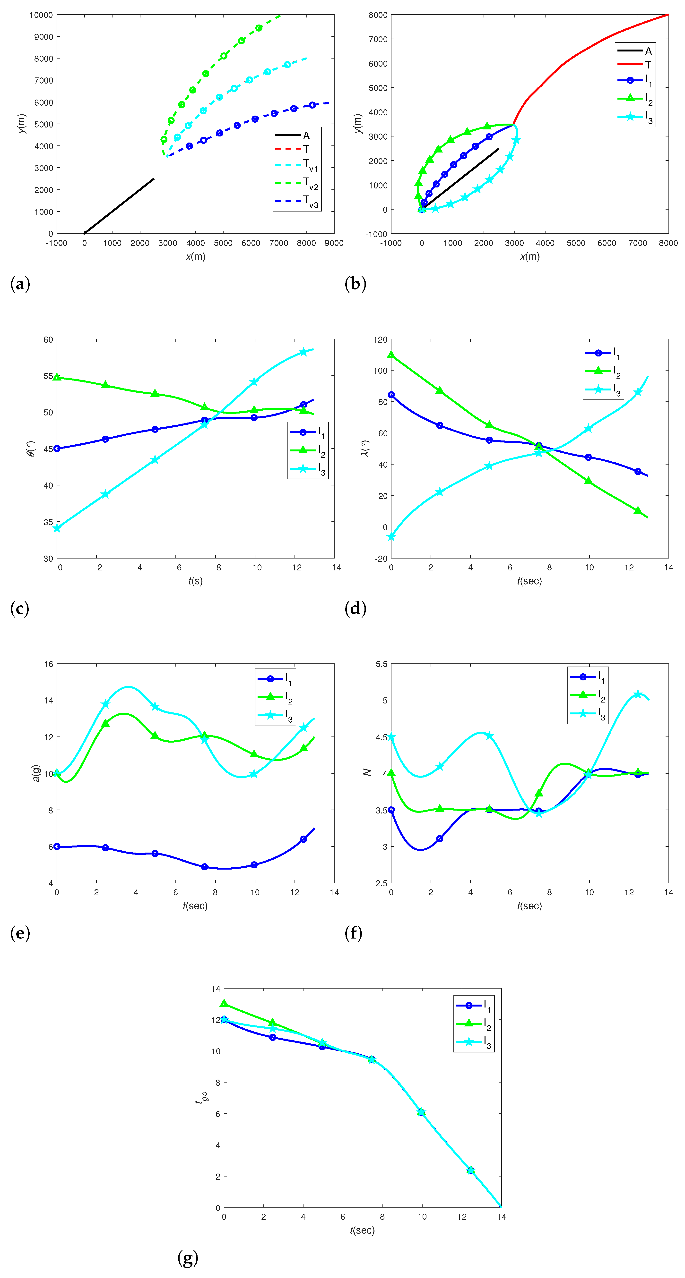
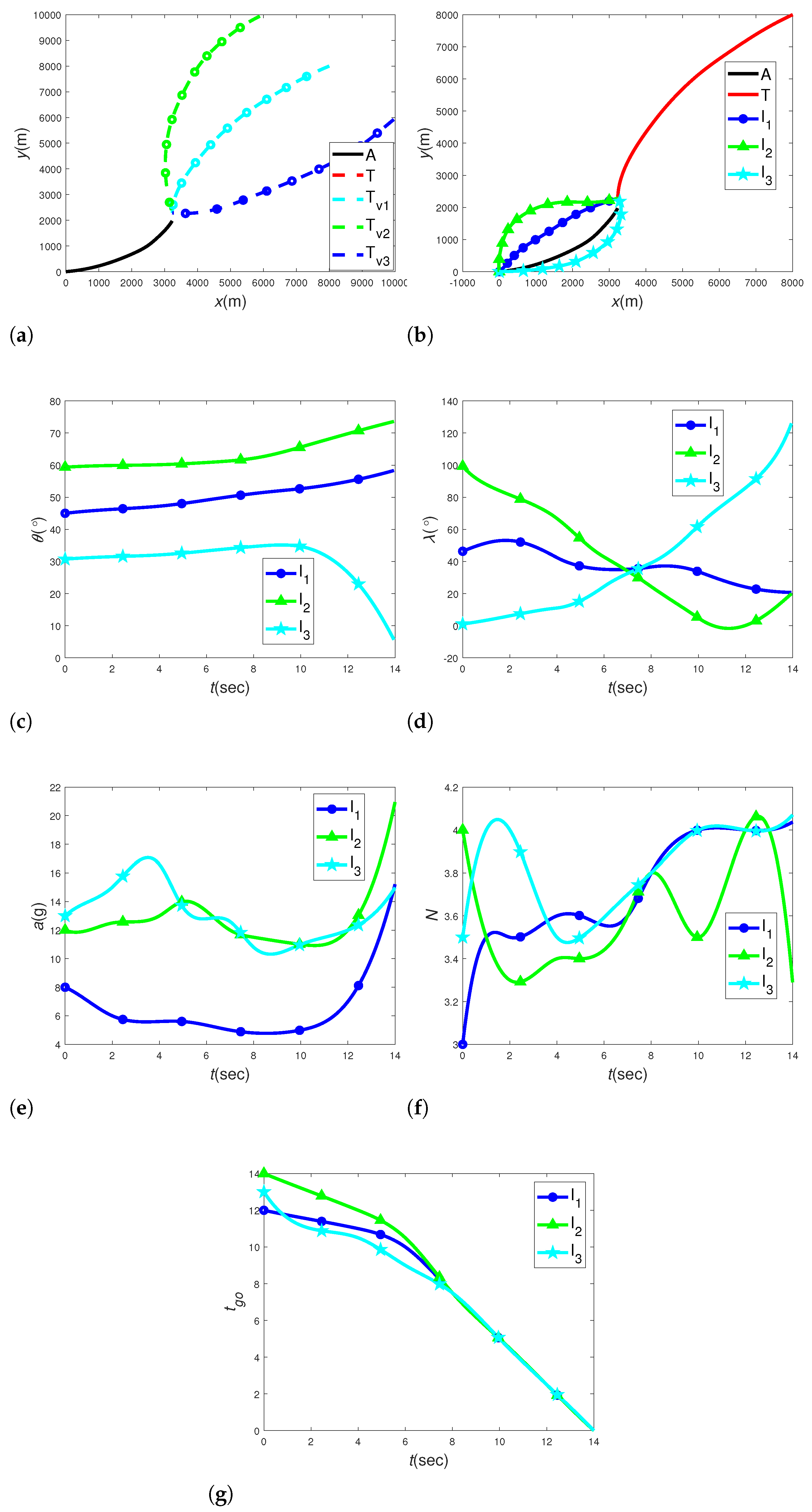
In this subsection, simulation experiments are conducted to validate the effectiveness of the proposed DECG law for interceptors while the aircraft executes no maneuvers when facing the attacking threat of the target. The results of the simulations are presented in Figure 8a–g. From Figure 8a,b, it is evident that when the fighter aircraft executes no maneuvers, the target also follows more direct and rapid trajectories, as illustrated by the real and virtual targets. Meanwhile, the interceptors successfully execute dynamic encircling maneuvers for both the real and virtual targets. Finally, the interceptors successfully intercept the real target, with at least one interceptor accurately intercepting the target. Furthermore, as the real and virtual targets do not create extensive escape areas due to the fighter aircraft’s lack of maneuvers, the interceptors execute minimal surrounding maneuvers throughout the process to conserve energy. This result also suggests that, in some cases, fighters can fly without maneuvering, thus indirectly assisting the interceptors in conserving energy consumption during intercepting the target. As depicted in Figure 8c,d, the values of the LOS angles and the azimuth angles remain within a reasonable range with the LOS angles changing smoothly and gradually converging to the designated values, which means the encircling is successful. In Figure 8e,f, it is observed that under the guide of the DECG law, the overload adopted by the interceptors remains below the maximum safe value, indicating adequate capabilities. The DECG law effectively controls the overload of the interceptors, maintaining it at a low and reasonable level, especially in the early stage of the interception process. Regarding the time control aspect, Figure 8g illustrates that although the t g o values for the interceptors may differ due to varying initial conditions, the three t g o values swiftly converge to the t * under the time control strategy. The time control strategy proves crucial for achieving successful encircling interception, and the DECG law has effectively implemented this strategy.

3.2. Case 2: Fighter Aircraft Makes Evasion Maneuvers

In this subsection, simulations are conducted to verify the effectiveness of the proposed DECG law when the aircraft makes designated maneuvers under the law in Equation (43). The simulation results are presented Figure 9a–g.
a A x = 4 g a A y = 1.5 g
From Figure 9a,b, it is observed that when the fighter aircraft employs designated maneuvers, the target’s trajectories are more curved and sharper compared to case 1. Additionally, due to the aircraft’s maneuvers, both the real and virtual targets create larger escape areas, prompting the interceptors to execute broader encircling maneuvers initially to establish the encircling situation for the target. Meanwhile, due to overload control, the interceptors still maintain reasonable and feasible acceleration. Eventually, the interceptors successfully complete the encircling process and intercept the real target even with a longer time. This result also shows that, in some cases, the fighter’s maneuvering flight for a safe withdrawal can indirectly lead to the need for the interceptors to make greater maneuvers to intercept the target during the interception and longer interception time. As depicted in Figure 9c,d, the values of the LOS angles and the azimuth angles also remain within a reasonable range with LOS angles changing smoothly and gradually converging to the designated values. In Figure 9e,f, it is observed that under the guide of the DECG law, the overload adopted by the interceptors also remains below the maximum safe values. Figure 9g illustrates that the three t g o values for the interceptors also converge under the time control strategy. However, compared to Case 1, this process takes longer because the interceptors require more time to adjust their trajectories for encircling the targets due to the target’s evasion maneuvers.

3.3. Case 3: Comparison to the CPNG Guidance

In this subsection, to further validate the superiority of the DECG law, comparative simulations are performed with the CPNG law, which is illustrated in Equation (44) [31]. t ¯ g o is the expected interception time given in advance. The simulation conditions remain the same as those in case 2. The results of the simulations are presented in Figure 10a–e. From Figure 10a, it is evident that, in accordance with the terminal requirements, only the DECG law has successfully achieved dynamic encircling interception for the target and all the interceptors can achieve the successful miss distance by the DECG law. However, the dynamic encircling interception cannot be achieved and only one interceptor can intercept the target with more energy consumed under the CPNG law. The reason for these results is that the DECG law can dynamically update the precise cooperation time and provides more optimal control inputs, it enables the three interceptors to reach the assigned point in less time and with less energy. It is noteworthy that the CPNG law, with a constant proportional coefficient, requires high overload at the final interception point, representing a vulnerability for the interceptors. As shown in Figure 10b,c, the values of the LOS angles and the azimuth angles remain within a reasonable range under both guidance laws. However, it is apparent that the change rates and maximum values under the DECG law are smoother and more moderate. In Figure 10d,e, it is observed that the maximum overload values are considerably smaller than those under the CPNG law throughout the process. Moreover, at the beginning and the final period, the overload required by the CPNG law exceeds the available value, significantly surpassing that demanded by the DECG law. The DECG law can compute the optimal proportional coefficient during the interception process, rendering it more feasible and reasonable than the constant values used in the CPNG law.
t ^ go , i ( t ) = r i ( t ) V i 1 + θ i 2 ( t ) 2 2 N i 1 a i = N i V i λ ˙ i ( t ) + K i r i ( t ) t ¯ go ( t ) t ^ go , i ( t )

3.4. Case 4: Robustness Analysis

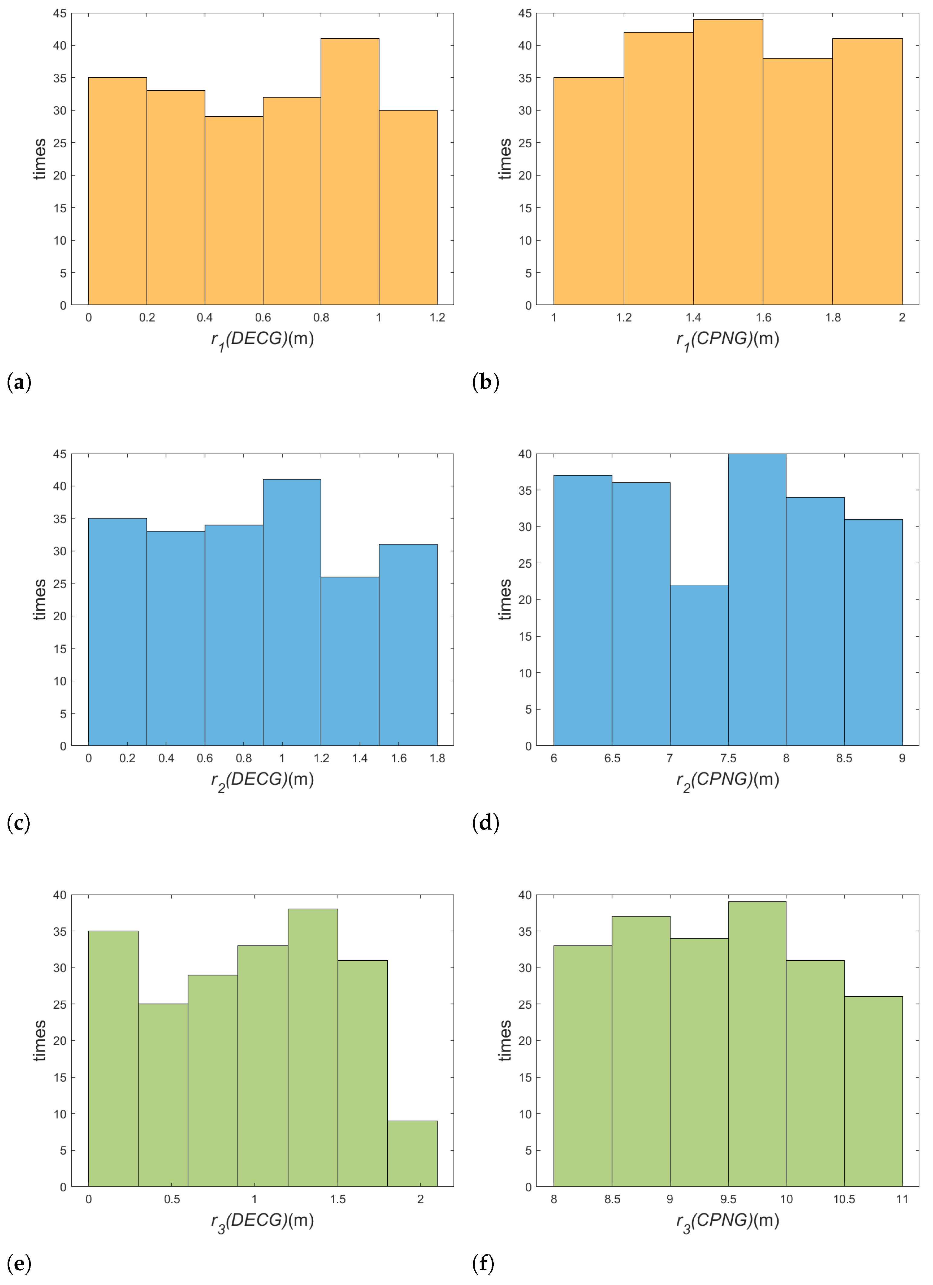
In this subsection, to further validate the robustness and superiority of the DECG law, 200 Monte Carlo runs are conducted. The initial positions are set as normal distributions with zero means and standard deviations of 100 m. The state feedback deviation and control inputs are set with a 5% deviation. The simulation conditions are the same as those of the Section 3.3. The simulation results are presented in Figure 11a–f. It can be observed that the interceptor 1 can always, intercept the target with an average miss distance of 0.59 m and 1.59 m under the DECG and CPNG law, respectively, which means the DECG law has more precise control. Moreover, compared to the CPNG law, the DECG law controls all the interceptors to achieve a shorter miss distance, indicating better interception effectiveness. What is more, the average maximum overload of interceptors by DECG is 12 g, while the value of the successful interceptor under CPNG is 18 g. CPNG uses higher control overloads, often exceeding the effective overload, in order to regulate the time it takes for the interceptors to reach the point of interception, which is unrealistic in practice. Moreover, due to the existence of disturbance, CPNG cannot dynamically update the accurate cooperative time, resulting in its interceptor group not being able to achieve a simultaneous interception time, so it is difficult to realize dynamic cooperative encircling. Therefore, the DECG law demonstrates higher robustness in the presence of errors and noise than the CPNG law.

4. Conclusions

To address the threats for the fighter aircraft posed by the emergence of superior target, a DECG law addressing multiple constraints is established to provide reference for enhancing the existing fighter aircraft self-protection system. The following conclusions are derived:
(1)
The proposed dynamic encircling interception strategy of the DECG law is able to simply and effectively utilize the numerical superiority of the inferior interceptor group, and able to well accomplish the contractual encircling and interception for the superior target. In addition, this strategy can also make the cooperative time constraints easier to process.
(2)
The remodeled kinematics and the convex optimization method can satisfy multiple constraints and have better control precision with good computational efficiency, which also makes the guidance problem more practical.
(3)
The proposed DECG law has better robustness than the CPNG law in the same simulation conditions, and the interceptors consume less energy under the DECG law, which gives full play to the advantages of the inferior interceptors. What is more, DECG is able to satisfy multiple constraints and still have high control accuracy.
Future work will be focused on the three-dimensional DECG law considering the constraints of the FOV angle and the presence of multiple superior targets.

Author Contributions

Conceptualization, D.Y. and X.Y.; methodology, D.Y. and X.Y.; software, D.Y.; formal analysis, D.Y.; writing—original draft preparation, D.Y.; writing—review and editing, X.Y.; visualization, D.Y.; supervision, X.Y.; funding acquisition, X.Y. All authors have read and agreed to the published version of the manuscript.

Funding

This research received no external funding.

Data Availability Statement

All data used during the study appear in the submitted article.

Conflicts of Interest

All of the authors declare that they have no known competing financial interests or personal relationships that could appear to influence the work reported in this paper.

References

  1. Garcia, E.; Casbeer, D.W.; Pachter, M. Cooperative Strategies for Optimal Aircraft Defense from an Attacking Missile. J. Guid. Control Dyn. 2015, 38, 1510–1520. [Google Scholar] [CrossRef]
  2. Liang, L.; Deng, F.; Peng, Z.; Li, X.; Zha, W. A Differential Game for Cooperative Target Defense. Automatica 2019, 102, 58–71. [Google Scholar] [CrossRef]
  3. Von Moll, A.; Garcia, E.; Casbeer, D.; Suresh, M.; Swar, S.C. Multiple-Pursuer, Single-Evader Border Defense Differential Game. J. Aerosp. Inf. Syst. 2020, 17, 407–416. [Google Scholar] [CrossRef]
  4. Liang, H.; Wang, J.; Liu, J.; Liu, P. Guidance Strategies for Interceptor against Active Defense Spacecraft in Two-on-Two Engagement. Aerosp. Sci. Technol. 2020, 96, 105529. [Google Scholar] [CrossRef]
  5. Liu, F.; Dong, X.; Li, Q.; Ren, Z. Robust Multi-Agent Differential Games with Application to Cooperative Guidance. Aerosp. Sci. Technol. 2021, 111, 106568. [Google Scholar] [CrossRef]
  6. Liu, F.; Dong, X.; Li, Q.; Ren, Z. Cooperative Differential Games Guidance Laws for Multiple Attackers against an Active Defense Target. Chin. J. Aeronaut. 2022, 35, 374–389. [Google Scholar] [CrossRef]
  7. Yan, X.; Lyu, S. A Two-Side Cooperative Interception Guidance Law for Active Air Defense with a Relative Time-to-Go Deviation. Aerosp. Sci. Technol. 2020, 100, 105787. [Google Scholar] [CrossRef]
  8. Song, J.; Song, S.; Xu, S. Three-Dimensional Cooperative Guidance Law for Multiple Missiles with Finite-Time Convergence. Aerosp. Sci. Technol. 2017, 67, 193–205. [Google Scholar] [CrossRef]
  9. Weiss, M.; Shima, T. Minimum Effort Pursuit/Evasion Guidance with Specified Miss Distance. J. Guid. Control. Dyn. 2016, 39, 1069–1079. [Google Scholar] [CrossRef]
  10. Sinha, A.; Kumar, S.R.; Mukherjee, D. Cooperative Salvo Based Active Aircraft Defense Using Impact Time Guidance. IEEE Control Syst. Lett. 2021, 5, 1573–1578. [Google Scholar] [CrossRef]
  11. Kang, S.; Wang, J.; Li, G.; Shan, J.; Petersen, I.R. Optimal Cooperative Guidance Law for Salvo Attack: An MPC-Based Consensus Perspective. IEEE Trans. Aerosp. Electron. Syst. 2018, 54, 2397–2410. [Google Scholar] [CrossRef]
  12. Li, Y.; Zhou, H.; Chen, W. Three-Dimensional Impact Time and Angle Control Guidance Based on MPSP. Int. J. Aerosp. Eng. 2019, 2019, e5631723. [Google Scholar] [CrossRef]
  13. Li, G.Y.; Yu, Z.; Zhang, Y. Cooperative Guidance Law with Angle Constraint to Intercept Maneuvering Target. J. Syst. Eng. Electron. 2019, 41, 626–635. [Google Scholar]
  14. Lyu, T.; Lyu, Y.Y.; Li, C.J.; Guo, Y.N. Finite Time Cooperative Guidance Law for Multiple Missiles with Line-of-sight Angle Constraint. Acta Armamentarii 2018, 39, 305. [Google Scholar]
  15. Kumar, S.R.; Mukherjee, D. Cooperative Active Aircraft Protection Guidance Using Line-of-Sight Approach. IEEE Trans. Aerosp. Electron. Syst. 2021, 57, 957–967. [Google Scholar] [CrossRef]
  16. Li, C.; Wang, J.; Huang, P. Optimal Cooperative Line-of-Sight Guidance for Defending a Guided Missile. Aerospace 2022, 9, 232. [Google Scholar] [CrossRef]
  17. Su, W.; Li, K.; Chen, L. Coverage-Based Cooperative Guidance Strategy against Highly Maneuvering Target. Aerosp. Sci. Technol. 2017, 71, 147–155. [Google Scholar] [CrossRef]
  18. Su, W.; Shin, H.S.; Chen, L.; Tsourdos, A. Cooperative Interception Strategy for Multiple Inferior Missiles against One Highly Maneuvering Target. Aerosp. Sci. Technol. 2018, 80, 91–100. [Google Scholar] [CrossRef]
  19. Zhang, B.; Zhou, D.; Li, J.; Yao, Y. Coverage-Based Cooperative Guidance Strategy by Controlling Flight Path Angle. J. Guid. Control Dyn. 2022, 45, 972–981. [Google Scholar] [CrossRef]
  20. Yan, X.; Kuang, M.; Zhu, J.; Yuan, X. Reachability-Based Cooperative Strategy for Intercepting a Highly Maneuvering Target Using Inferior Missiles. Aerosp. Sci. Technol. 2020, 106, 106057. [Google Scholar] [CrossRef]
  21. Garcia, E. Cooperative Target Protection from a Superior Attacker. Automatica 2021, 131, 109696. [Google Scholar] [CrossRef]
  22. Sinha, A.; Kumar, S.R. Supertwisting Control-Based Cooperative Salvo Guidance Using Leader–Follower Approach. IEEE Trans. Aerosp. Electron. Syst. 2020, 56, 3556–3565. [Google Scholar] [CrossRef]
  23. Chen, Z.; Wei, W.; Chen, W. Reinforcement Learning-based Intelligent Guidance Law for Cooperative Attack of Multiple Missiles. Acta Armamentarii 2021, 42, 1638. [Google Scholar] [CrossRef]
  24. Yujie, S.; Hua, X.; Zhe, L. Three-Dimensional Adaptive Neural Network Guidance Law against Maneuvering Targets. J. Syst. Simul. 2021, 33, 453. [Google Scholar] [CrossRef]
  25. Luo, D.; Fan, Z.; Yang, Z.; Xu, Y. Multi-UAV Cooperative Maneuver Decision-Making for Pursuit-Evasion Using Improved MADRL. Def. Technol. 2023, in press. [Google Scholar] [CrossRef]
  26. Xia, J.; Luo, Y.; Liu, Z.; Zhang, Y.; Shi, H.; Liu, Z. Cooperative Multi-Target Hunting by Unmanned Surface Vehicles Based on Multi-Agent Reinforcement Learning. Def. Technol. 2023, 29, 80–94. [Google Scholar] [CrossRef]
  27. Jiang, H.; An, Z.; Yu, Y.; Chen, S.; Xiong, F. Cooperative Guidance with Multiple Constraints Using Convex Optimization. Aerosp. Sci. Technol. 2018, 79, 426–440. [Google Scholar] [CrossRef]
  28. Zhou, J.; Wu, X.; Lv, Y.; Li, X.; Liu, Z. Recent Progress on the Study of Multi-vehicle Coordination in Cooperative Attack and Defense: An Overview. Asian J. Control 2022, 24, 794–809. [Google Scholar] [CrossRef]
  29. Pachter, M.; Moll, A.V.; Garcia, E.; Casbeer, D.; Milutinović, D. Cooperative Pursuit by Multiple Pursuers of a Single Evader. J. Aerosp. Inf. Syst. 2020, 17, 371–389. [Google Scholar] [CrossRef]
  30. Wang, Z.; Fu, W.; Fang, Y.; Wu, Z.; Wang, M. Cooperative Guidance Law against Highly Maneuvering Target with Dynamic Surrounding Attack. Int. J. Aerosp. Eng. 2021, 2021, 6623561. [Google Scholar] [CrossRef]
  31. Zhao, J.; Zhou, R. Unified Approach to Cooperative Guidance Laws against Stationary and Maneuvering Targets. Nonlinear Dyn. 2015, 81, 1635–1647. [Google Scholar] [CrossRef]
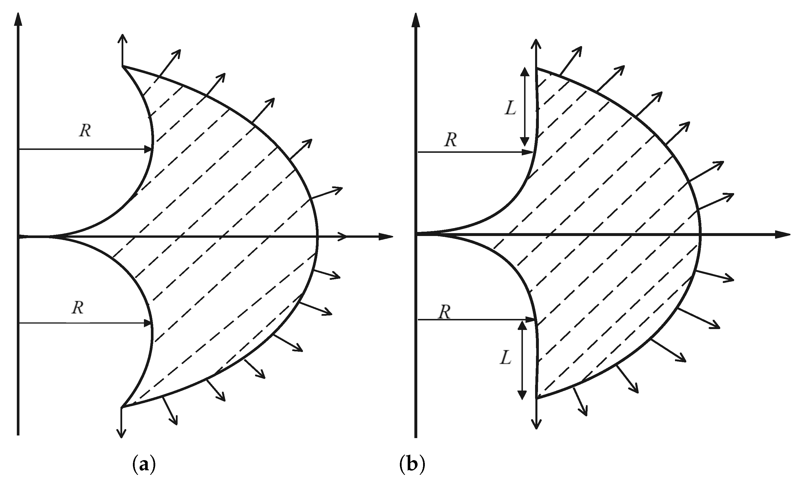
Figure 2. Escaping area of the target with different escaping time, which includes (a) less escaping time; (b) more escaping time.
Aerospace 11 00375 g002
Figure 3. Dynamic encircling strategy.
Aerospace 11 00375 g003
Figure 4. Virtual targets’ escaping points geometry.
Aerospace 11 00375 g004
Figure 5. Multiple interceptors intercepting virtual targets.
Aerospace 11 00375 g005
Figure 6. Cooperative time control strategy.
Aerospace 11 00375 g006
Figure 7. The DECG calculation process.
Aerospace 11 00375 g007
Figure 8. Dynamic encircling interception with fighter aircraft making no maneuvers: (a) trajectory of the ‘targets’; (b) trajectory of the interception; (c) LOS angle; (d) azimuth angle; (e) acceleration; (f) proportional coefficient; (g) remaining flight time.
Aerospace 11 00375 g008
Figure 9. Dynamic encircling interception with fighter aircraft making maneuvers: (a) trajectory of the ‘targets’; (b) trajectory of the interception; (c) LOS angle; (d) azimuth angle; (e) acceleration; (f) proportional coefficient; (g) remaining flight time.
Aerospace 11 00375 g009
Figure 10. Comparison with the PNG with fighter aircraft making maneuvers: (a) trajectory of the interception; (b) LOS angle; (c) azimuth angle; (d) acceleration; (e) proportional coefficient.
Aerospace 11 00375 g010
Figure 11. Monte Carlo experiment results: (a) miss distance of D1 with DECG; (b) miss distance of I1 with CPNG; (c) miss distance of I2 with DECG; (d) miss distance of I2 with CPNG; (e) miss distance of I3 with DECG; (f) miss distance of I3 with CPNG.
Aerospace 11 00375 g011
Table 1. Numerical simulation parameters.
ParValuesUnitsParValuesUnits
X T [8000 8000]m X A [0 0]m
X I 1 [0 0]m X I 2 [0 0]m
X I 3 [0 0]m v A 1000 m s 1
v A [300 300] m s 1 v I i 600 m s 1
a A m a x 5g a T m a x 30g
a I i m a x 20g λ T −180deg
λ I i [45 100 0]deg λ A 45deg
N T 4/ N A 4/
t p m a x 12s δ t 2s
δ [0.01 0.01 0.01]/ θ * 1.57rad
Disclaimer/Publisher’s Note: The statements, opinions and data contained in all publications are solely those of the individual author(s) and contributor(s) and not of MDPI and/or the editor(s). MDPI and/or the editor(s) disclaim responsibility for any injury to people or property resulting from any ideas, methods, instructions or products referred to in the content.