Article

Design and Analysis of Low-Gravity Simulation Scheme for Mars Ascent Vehicle

1
National Key Laboratory of Aerospace Mechanism, Nanjing University of Aeronautics and Astronautics, Nanjing 211100, China
2
Key Laboratory of Exploration Mechanism of the Deep Space Planet Surface, Ministry of Industry and Information Technology, Nanjing University of Aeronautics and Astronautics, Nanjing 211100, China
*
Author to whom correspondence should be addressed.
These authors contributed equally to this work.
Aerospace 2024, 11(6), 424; https://doi.org/10.3390/aerospace11060424
Submission received: 3 April 2024 / Revised: 10 May 2024 / Accepted: 17 May 2024 / Published: 23 May 2024
(This article belongs to the Section Aeronautics)

Abstract

:
The sample carried back by the Mars Ascent Vehicle (MAV) is a potential flagship mission of deep space exploration in recent years. A low-gravity simulation experiment is an effective method and a necessary stage for verifying the performance of the MAV launch dynamic in Earth’s gravity. In this paper, the uniqueness of low-gravity simulation is illustrated by the classical pulley balance method for the high dynamic process of a test model of the MAV. Its movement direction is the same as the compensation force, which leads to the relaxation of the sling and the failure of the compensation force in traditional cable suspension. Here, three cable suspension schemes including an improved pulley balancing scheme based on a coordinate transformation scheme and based on a dynamic pulley group scheme are proposed. For the actual launch condition of the MAV, the motion state of the ascent under the schemes and the real Mars launch are compared, which proves the feasibility of the schemes. Among them, the improved pulley balancing scheme has the best gravity compensation effect, and the error between the average value and the required value is the smallest, only 1%.

1. Introduction

Mars is the closest planet to Earth in the solar system. Both China and the United States have successfully achieved landing and roving exploration on the surface of Mars. The next phase is the Mars sample return mission, deemed a significant direction for development. The research into Martian soil will advance mankind’s analysis of this planet, whose natural environment is very similar to the Earth’s, and provide assistance for future human migration to Mars.
The concept of Mars sampling has existed since the 1950s. The initial conceptual design of the Mars Ascent Vehicle began in 1996 at the Jet Propulsion Laboratory (JPL) [1]. In its original design, the MAV was envisioned as a standalone space vehicle with a payload and propulsion system, intended to be rocketed into proper orbit [2]. The orbital transfer sample was redesigned in the first major iteration to fit within strict constraints of mass and size. It was transformed into a passive, non-cooperative spherical system that was encased within a cylindrical ascent vehicle for the rendezvous orbiter [3]. Consequently, the external configuration of the ascent vehicle was essentially finalized.
The launch of the MAV presents unique mechanical challenges that differ from those encountered under Earth’s gravity conditions. To ensure technical feasibility during the Mars takeoff phase, low-gravity simulation of the ascent vehicle is necessary. The research and application of low-gravity simulation for spacecraft on the ground has a long history with numerous results, which can be divided into the tower drop method, the gas/water float method, cable suspension, etc. [4]. Xu et al. [5] designed a low-gravity test system for ultra-large inertia spacecraft using a single-axis air floating platform, two three-degree-of-freedom air floating platforms, and air cushion auxiliary supports and trusses. However, due to the huge cost, this solution only involves system design and simulation verification. The cable suspension is widely used due to its comprehensive advantages, whose central idea is to compensate for gravity by using a sling to apply a plumb bob upward force on the spacecraft [6]. A high-precision, high-efficiency, and fast-response low-gravity simulation system for the motion process of the multiple-degree-of-freedom space manipulator was designed by Sun [7] and can realize gravity unloading while ensuring that the movement of the manipulator is not disturbed. Jia [8] developed a gravity compensation system that adapts to objects of multiple sizes and arbitrary shapes, and established corresponding dynamic models and kinematic models. Furthermore, a novel rigid-elastic coupling suspension gravity compensation system was proposed by Jia [9] that significantly improved the compensation accuracy of the system. De Stefano and others [10] proposed a gravity compensation strategy for a seven-degree-of-freedom space manipulator to solve the torque limitation problem encountered in a 1 g experimental environment by a joint motor designed for 0 g. Cao et al. [11] aimed at the control problem of low-gravity simulation systems based on the suspension method, and used a traditional PID control method with a radial basis function (RBF) neural network to reduce the error of the constant tension control problem. The large-scale gravity compensation system developed by Liu et al. [12] has been successfully applied to validate the maneuverability of the lunar rover, which compensates for 5/6 of the rover’s gravity on Earth in a square test site of 900 square meters. Li et al. [13] designed an active gravity compensation system for a six-degree-of-freedom free-flying robot based on the robot’s compensating force and workspace. The experimental system contains an active suspension mechanism consisting of primary and secondary active rotating arms and a cable suspension device with passive counterweights, which extends the workspace of the robotic arm and improves the accuracy of the compensation of the rope force. Jiang et al. [14] conducted a low-gravity simulation test on new cubic rovers that traverse by hopping systems, and the experimental results provide significant insight into the attitude-adjusting behavior of cubic rovers. In terms of the unpowered low-speed landing of spacecraft, Hou et al. [15] combined a non-contact/frictionless M-QZS mechanism with a stroke amplification structure, providing a new method for the micro-low-gravity simulation testing of lunar vehicles on the ground. Landing tests under different external forces were conducted, successfully reproducing the bouncing phenomenon of the lunar vehicle when landing in a microgravity environment. Chen et al. [16] took a different approach by deriving a dynamic similarity law for deep space landers and proposed a new method for low-gravity simulation on the ground, and verified the accuracy of the method through landing experiments. In the study of large space mesh antenna deployment, simulations conducted by Zhao et al. [17] showed that the incomplete unloading of gravity has a non-negligible impact on the deployment dynamics of the entire antenna, and the number and location of suspended nodes influence the compensation effect. Meanwhile, the analytical model proposed has wide applicability to similar flexible structural systems requiring gravity compensation. For other types of spacecraft, such as circular thin-film solar wings, Yang et al. [18] conducted low-gravity simulation studies. For astronaut training, Xiang et al. [19] designed a new suspended gravity compensation system to simulate a microgravity walking environment. Zhang et al. [20]. combined the lasso-driven wire tension mechanism and a passive gravity compensation mechanism based on a parallel linkage to compensate for part of the astronaut’s body gravity to realize different low-gravity environments.
It can be seen from the aforementioned research that low-gravity simulation experiments have become a crucial component of successful spacecraft missions. Distinct types of spacecraft have diverging requirements for gravity simulation systems, necessitating design and optimization tailored to their unique characteristics. However, most current low-gravity simulation experiments are mainly focused on static or quasi-static working conditions. The Mars Ascent Vehicle (MAV), which is erected and launched from a platform on Mars, represents a novel class of spacecraft. Simulating the high-speed and dynamic launch process of the MAV in a low-gravity environment is thus of significant scientific and engineering importance.
In this paper, the existing low-gravity simulation methods are detailed, and are aimed at the low-speed deployment and unpowered descent process of the spacecraft. There is basically no relevant research on low-gravity simulation for the process of launching a spacecraft from extraterrestrial objects. Therefore, for the future Mars sample return mission, we designed several low-gravity simulation schemes for the process of the launch tube of the MAV. Firstly, kinematic analysis and simulation are carried out for the ideal launch process of a certain ascender to obtain its motion state as a benchmark for subsequent standard program evaluation. Secondly, the classical pulley balancing method is used to explicitly point out the biggest challenge that exists in the low-gravity simulation experiments of the MAV, which is the relaxation of the ropes due to the direction of the motion being the same as the compensating force in the high-speed dynamics. Finally, three solutions are proposed to address this unique problem in the low-gravity simulation of the ascender, and the effectiveness and accuracy of the proposed solutions are proven through simulation and comparison.

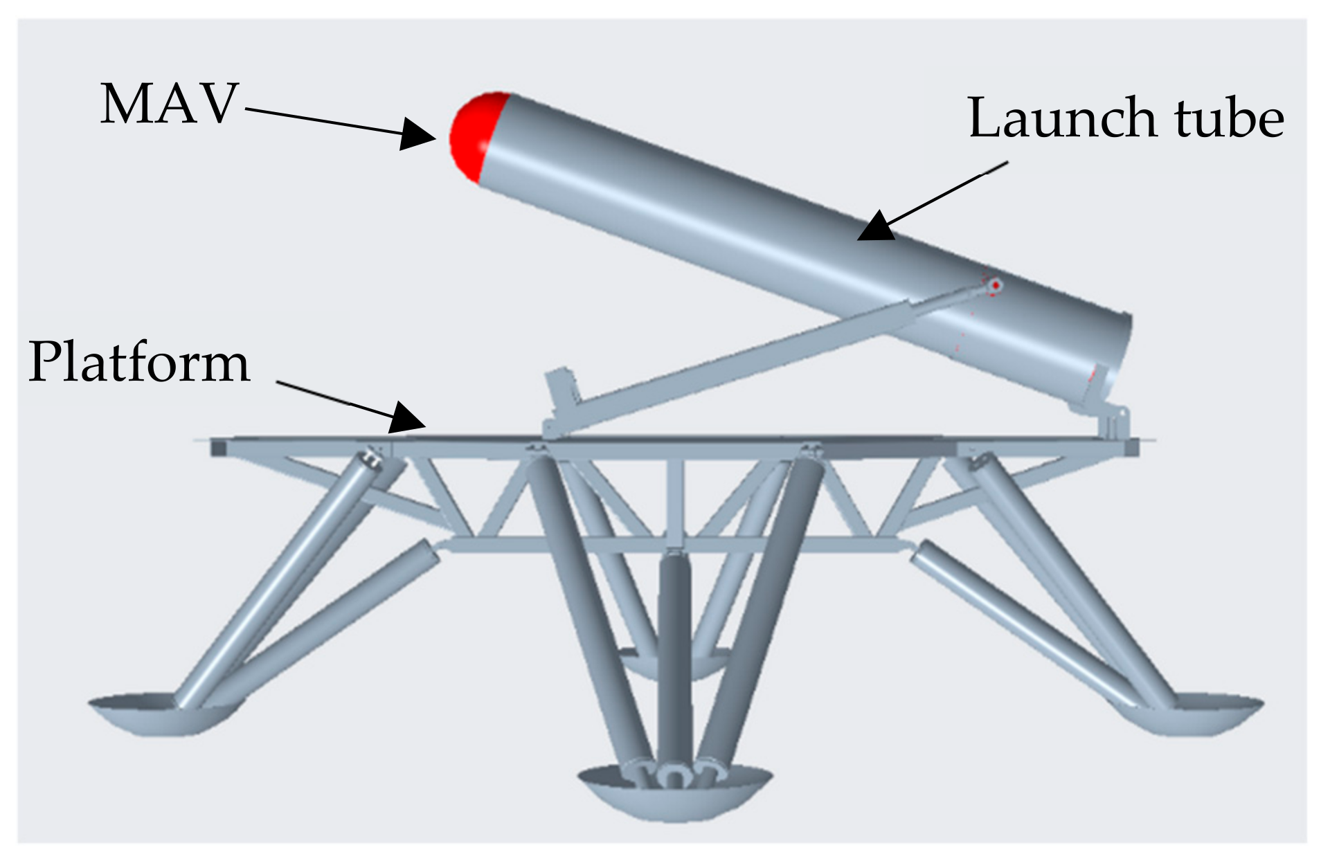
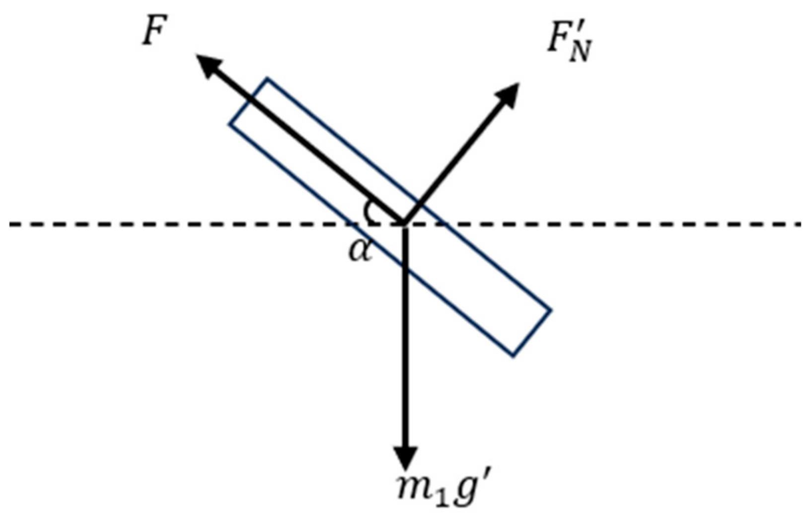
2. MAV Kinematic Analysis

The purpose of the low-gravity simulation experiment is to make the motion state of the ascender in the Earth’s gravity environment as close as possible to that of the launch process in the Mars gravity environment so as to further validate the property of the ascent or landing platform. The property of the MAV and the launch tube are shown in Table 1. Low-gravity simulation experiments are needed for the highly dynamic process of launching out of the tube.
Figure 1 shows the 3D model of the MAV and the platform. The platform is used to land on Mars and launch the MAV. The launch tube is a device used to store and secure the MAV. The MAV looks like a missile.
A kinematic analysis of the process of launching out of tube in the Martian gravity environment is performed and the following assumptions are made: ① The low-gravity simulation only considers the process of launching out of the tube, without taking into account aerodynamics and air resistance. ② Since the adapter exists and the engine thrust is large enough, friction is ignored. ③ Since the process of launching is extremely short, it is assumed that the support force is always present.
The force on the ascender in the tube is shown in Figure 2, from which the kinetic model of the ascender can be introduced as shown in Equation (1):
F m 1 g sin α = m 1 a m 1 g cos α = F N
where F is the ascender thrust, m 1 is the ascender mass, α is the launch inclination, F N is the tube support, and g is the gravitational acceleration in the Martian environment, with a value of 3.72 m / s 2 [21].
The state of motion of the ascender can be derived from Equation (2):
s 1 = 1 2 a t 2 v = a t
where s 1 is the length of the launching tube, v is the speed of the ascender, t is the time of out of the tube, and a is the acceleration of the ascender.
The ascender has a complete out-of-tube time of 0.436 s , an acceleration of 26.3048 m / s 2 , and a velocity of 11.4689   m / s when it is completely out of the tube.
Equation (3) is the kinematic model of the ascender:
F sin α + F N cos α m 1 g = m 1 a x F cos α F N sin α = m 1 a y
where a x is the lateral acceleration of the ascender, and a y is the longitudinal acceleration of the ascender.
According to the dynamics model, the kinematics model, and the parameters of the MAV, the simulation the process of launching out of the tube is carried out with MATLAB under the condition of α as 50 degrees. The results are shown in Figure 3. In the ideal state, the ascender moves with a constant acceleration of 26.3048 m / s 2 during the process of launching, with a maximum velocity of 11.4689   m / s in the end. The ascender’s launch out of the tube is done at an extremely fast speed and in a very short time. Gravity unloading for such a highly dynamic process has never been encountered in previous studies, so a new scheme needs to be investigated in order to accomplish low-gravity simulation experiments. In addition, the ideal state of motion of the ascender is an important indicator to verify the effectiveness of gravity unloading.

3. Uniqueness of MAV Low-Gravity Simulation

Classical Pulley Balancing Cable Suspension Scheme

The criterion for gravity unloading of an ascender using the cable suspension is that the direction of the compensating force of the sling is opposite to the direction of gravity, and the magnitude is constantly equal to the mass of the object to be lifted multiplied by the difference in gravitational acceleration of the Earth and Mars. In the design of the initial scheme, it was proposed to use the pulley balancing method for gravity compensation, which is to use the characteristics of the fixed pulley block for passive gravity unloading.
It should provide a concise and precise description of the experimental results, their interpretation, and the experimental conclusions that can be drawn. The specific cable suspension scheme design is shown in Figure 4. The ascender test product and corresponding mass counterweights are suspended at both ends of the fixed pulley block; fixed pulley No. 1 is fixed on the passive follower device, which is installed on the linear slide rail to follow the lateral displacement of the ascender; and fixed pulley No. 2 is fixed on the linear slide.
In the above scheme, the counterweight mass is calculated by Equation (4):
m 2 g = m 1 ( g g )
where m 2 is the mass of the counterweight.
In order to simulate the elastic properties of the sling, the “wire” shape module and the “truss” element type are used to simulate a sling in ABAQUS. The truss element type in ABAQUS determines that each finite element is hinged, so it can be used for the simulation of a sling. The multi-body dynamics explicit solver of ABAQUS was used to simulate the above solution. The result is as follows:
Figure 5a shows the speed of the ascender. The real motion state of the MAV is shown as a blue curve. It can be seen that the ascender completely exits the tube after 0.48 s, as data point 1 as the orange curve shows, which belongs to the classical cable suspension scheme, and the speed when exiting the tube is 10.5457 m / s . Its motion state is not consistent with the real motion state in the Martian environment but is similar to the motion state in the Earth’s gravity environment, indicating that the gravity of the ascender is not completely unloaded. Figure 5b shows the acceleration of the ascender under the Mars gravity environment and the classical suspension scheme. The blue curve represents the real motion of the MAV, as calculated by its dynamics model, which was established in Section 2. In the classical suspension scheme, due to the high-speed movement of the ascender, the rope cannot be in a tensioned state to follow the movement of the ascender, but there is still a small residual tension acting on the ascender. Due to the elastic properties of the rope, the axial force of the rope acting on the ascender will fluctuate during the process of rope relaxation, which will lead to fluctuations in the acceleration, as shown with the red curve.
Figure 6 shows the sling tension, which is almost 0 under this cable suspension scheme, indicating that the rope is completely relaxed. It further illustrates that no cable force is provided for gravity unloading. In addition, from a macro perspective, the rope relaxes from a completely tight state in a very short period of time, causing the tension to be zero. But in the finite element solution, since the time step is used to solve the process iteratively, the tensile force fluctuates an extremely amount at a certain time step due to the setting of the iteration step number and the characteristics of the rope.
The simulation results show that the passive following pulley balancing method cannot compensate for the gravity of the ascender. The superficial reason is that the cable force disappears due to the slack of the sling. However, after in-depth thinking and analysis, it was discovered that the low-gravity simulation of the ascender is completely different from previous spacecraft. For example, when the cable suspension is used in the antenna deployment process and the lander landing process, the direction of the sling’s tension is different from the direction of spacecraft movement. Therefore, the root cause of cable suspension failure is that the longitudinal movement direction of the ascender is the same as the tension direction. In addition, the movement speed of the ascender is extremely fast, which also causes the sling to relax and the cable suspension force to disappear.

4. Cable Suspension Scheme Design

4.1. Improved Pulley Balancing Cable Suspension Scheme

In the scheme in Section 3, the passive following device cannot track the lateral displacement of the ascender. Therefore, in this section, based on the classical pulley balance cable suspension scheme shown in Figure 4, the following device is designed as an active following device to synchronize it with the lateral displacement of the ascender.
During the launch process, the longitudinal acceleration of the ascender is transmitted along the sling, and the acceleration of fixed pulley No. 1 is completely equal to the lateral acceleration of the ascender, so the acceleration of the counterweight should be a y a x , that is, the difference between the longitudinal and the lateral acceleration of the ascender, and it is in the same direction as the acceleration of gravity. At this time, the counterweight block is in a weightless state. In order to keep the sling in a tensioned state, the mass of the counterweight should be increased to compensate for it. It is calculated by Equation (5):
F l = m 2 ( g ( a y a x ) ) F l = m 1 ( g g )
F l is the tension required for gravity unloading.
Under the conditions of launching at an angle of 50 degrees, according to the parameters of in Table 1 and Equations (3) and (5), it is calculated that the required rope tension F l is 2067 N and the required mass m 2 of the counterweight is 316.75 kg.

4.2. Cable Suspension Scheme Based on Coordinate Transformation

In Section 3, it was determined that the reason for the failure of the cable suspension is that the vertical movement of the ascender is in the same direction as the tension. Therefore, this section proposes a low-gravity cable suspension scheme based on the principle of coordinate transformation from the essence of the problem. The principle is similar to that of the attitude transformation of a spacecraft, which only changes the direction of the ascender motion but does not change its force, as shown in Figure 7.
The specific cable suspension scheme is shown in Figure 8. The coordinate transformation is used to change the movement direction of the ascender, and then gravity compensation is performed through the cable suspension. The No. 1 pulley is fixed at the active follower, which can move along the slide in synchronization with the ascender to ensure that the angle does not change, and the No. 2 pulley is fixed at the linear slide.
Whether on Mars or Earth, the support force provided by the launch tube to the ascender is passive and distorted, so the gravity on Mars is compensated by the tension and the gravity on Earth, as shown in Equation (6):
m 1 g F 2 = m 1 g cos ( φ π 2 ) F 1 = m 1 g sin ( φ π 2 )
where F 1 and F 2 are the components of the tension, as shown in Equation (7):
F 1 = m 2 g cos θ F 2 = m 2 g sin θ
where m 2 is the mass of the counterweight, and θ is the angle between the sling and the ascender.
Under the same conditions of launching at a 50-degree angle, according to the parameters of the ascender in Table 1 and Equations (3) and (6), it is calculated that the required mass m 2 is 74.23 kg, and θ is 68°.

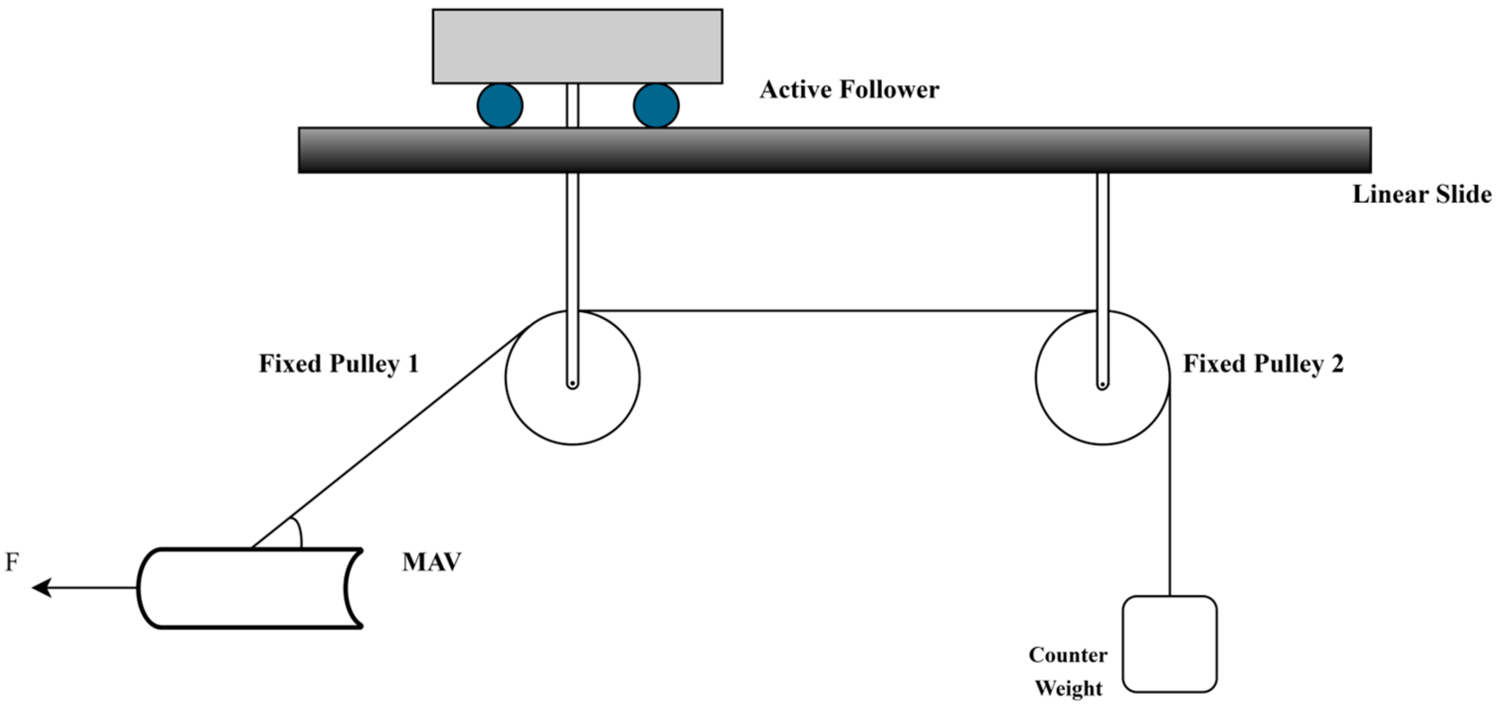
4.3. Cable Suspension Scheme Based on Movable Pulley Block

In the scheme in Section 4.2, the uniqueness of the low-gravity test of the ascender is addressed by changing its direction of motion to avoid gravity unloading failures due to the direction of the compensating force being the same as the motion. In this section, the properties of the movable pulley block are used to design a second low-gravity simulation scheme from the perspective that the sling is slack because the rotation around the fixed pulley is too late. The specific scheme is shown in Figure 9, where the No. 1 fixed pulley is also fixed on the active follower device, which tracks the lateral displacement of the ascender; the No. 2 fixed pulley is fixed on the linear slide rail; and both movable pulleys are connected to the ascender in series through the sling.
Since the displacement ratio of the movable pulley and the rope is always 2:1, the ratio of speed and acceleration is also 2:1. The counterweight mass is calculated by the following Equation (8):
2 F l m l 1 g F l 1 = 1 2 m l 1 a y a x 2 F l 1 m l 2 g F l 2 = 1 4 m l 2 a y a x F l 2 m 2 g = 1 4 m 2 a y a x F l = m 1 ( g g )
where m l 1 is the mass of the No. 1 movable pulley, m l 2 is the mass of the No. 2 movable pulley, F l 1 is the tension provided by the No. 1 movable pulley, F l 2 is the tension provided by the No. 2 movable pulley, and F l is the tension required for gravity compensation.
Under the same launch conditions, the designed mass of the No. 1 and No. 2 movable pulleys is 6.28 kg for each. According to the parameters of the ascender in Table 1 and Equations (3) and (8), the counterweight mass m 2 required is 902.925 kg.

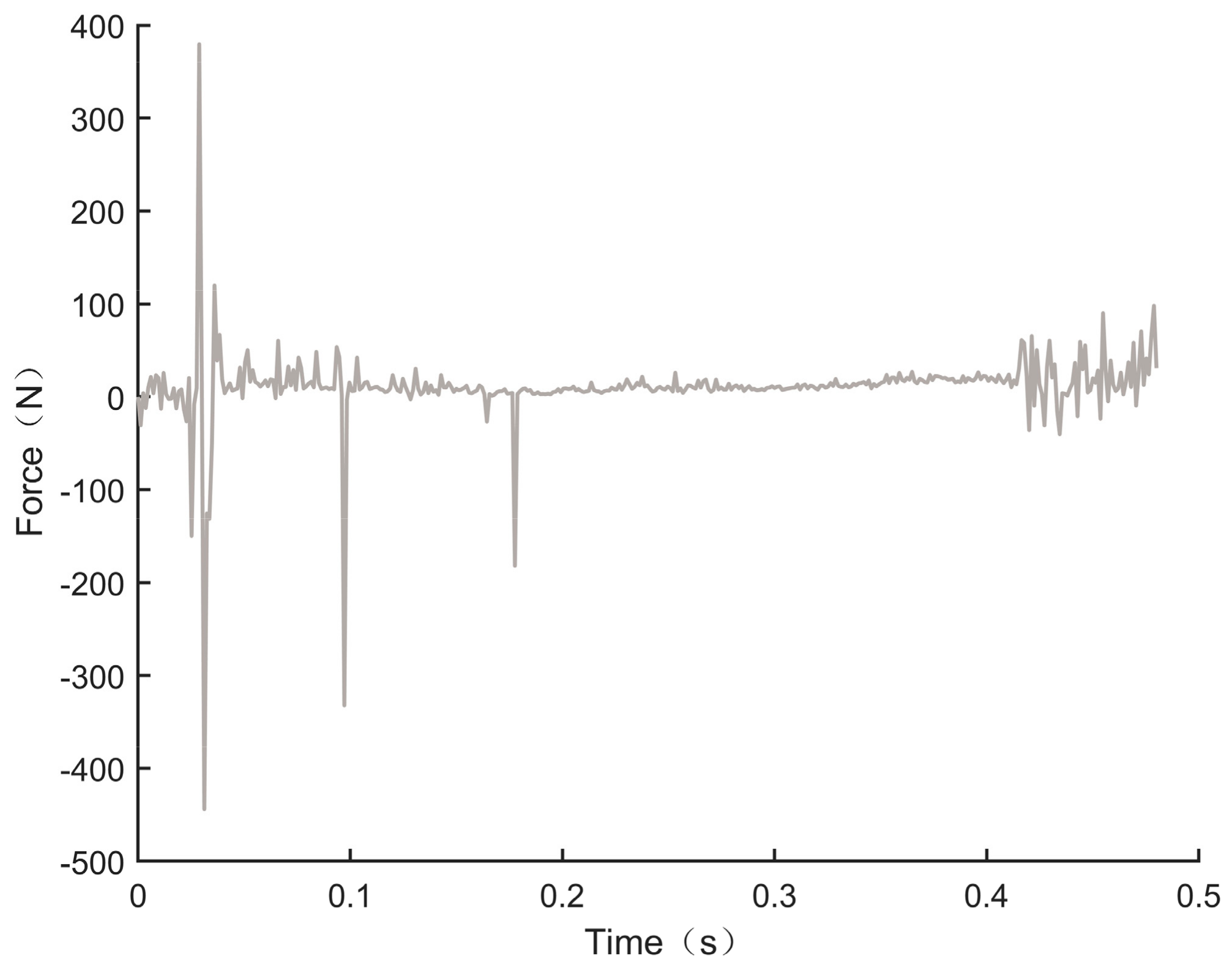
5. Simulation Verification

In order to ensure the consistency of the results, the same simulation environment as in Section 3 is used to simulate the 50-degree angle launch condition of the ascender described in Section 2 using the cable suspension schemes designed in Section 4.1, Section 4.2 and Section 4.3. The results are shown in Figure 10 and Figure 11.
Figure 10a shows the comparison results of the speed of the ascender among the three cable suspension schemes and the Martian environment. It can be seen that except for the cable suspension scheme based on the movable pulley group, which has a small fluctuation in the speed of the ascender in the period of 0.3 s to 0.4 s, all three cable suspension schemes can accurately restore the speed of the ascender in the Martian gravity environment. Figure 10b shows the acceleration comparison results. The improved pulley balance scheme can restore the acceleration preferably, and the fluctuation is relatively lower, with an average value of 26.8607 m / s 2 .
Figure 11 shows the comparison results of the tension under the three schemes and the tension required for gravity compensation of the ascender. Since the rope is an elastic body, the tension curves of the three solutions all fluctuate in a sinusoidal form. Among them, the tension of the coordinate transformation scheme fluctuates greatly, which is caused by this scheme being unable to restore the distorted support force. Of the other two schemes, the improved pulley balance cable suspension scheme has smaller tension fluctuations, as shown in Figure 10, with an average value of 2045 N. According to the result in Section 4.1, the required rope tension F l is 2067 N, so there is an error of only 1% from the required tension.

6. Conclusions

In this paper, the classical pulley balance method is used to illustrate the uniqueness of the low-gravity simulation of the ascent launch process. The direction of the compensation force is the same as the motion, and the process of the ascent out of the tube has high dynamic characteristics. These two factors together lead to the phenomenon of rope relaxation and compensation force failure in traditional cable suspension. Three new cable suspension schemes are designed from different angles, and simulation verification is carried out under the launching conditions. The results show that the improved pulley balance cable suspension scheme has the best low-gravity simulation effect, which can better restore the speed and acceleration of the MAV, and the fluctuation of the compensation force is small. Furthermore, our research provides theoretical guidance and preliminary verification for the future launch test of the Mars Ascent Vehicle in a low-gravity environment, and have significant practical engineering application value for ensuring the smooth launch of the ascent vehicle in the future.

Author Contributions

Conceptualization, C.W.; data curation, Z.H.; formal analysis, C.W.; project administration, J.C.; resources, H.W.; software, Z.H.; validation, H.W.; writing—original draft, C.L.; writing—review and editing, C.L. All authors have read and agreed to the published version of the manuscript.

Funding

This research was funded by the Basic Research Program (Natural Science Foundation) of Jiangsu Province, grant number BK20210297; the National Natural Science Foundation of China, grant number 52075242; and the Young Elite Scientists Sponsorship Program by CAST, grant number 2022QNRC001.

Data Availability Statement

The raw data supporting the conclusions of this article will be made available by the authors on request.

Conflicts of Interest

The authors declare no conflicts of interest.

References

  1. McCollum, L.T.; Schnell, A.; Yaghoubi, D.; Bean, Q.; McCauley, R.; Prince, A. Development Concepts for Mars Ascent Vehicle (MAV) Solid and Hybrid Vehicle Systems. In Proceedings of the 2019 IEEE Aerospace Conference, Big Sky, MT, USA, 2–9 March 2019; pp. 1–10. [Google Scholar] [CrossRef]
  2. Shotwell, R. History of Mars Ascent Vehicle Development over the Last 20 Years. In Proceedings of the 2016 IEEE Aerospace Conferenc, Big Sky, MT, USA, 5–12 March 2016; pp. 1–11. [Google Scholar] [CrossRef]
  3. Prince, A.; Kibbey, T.; Karp, A. A Design for a Two-Stage Solid Mars Ascent Vehicle. In Proceedings of the AIAA Propulsion and Energy 2019 Forum, Indianapolis, IN, USA, 19–22 August 2019; pp. 1–18. [Google Scholar] [CrossRef]
  4. Wang, W.; Tang, X.; Shao, Z.; Yang, J.; Yi, W. Design and Analysis of a Wire-Driven Parallel Mechanism for Low-Gravity Environment Simulation. Adv. Mech. Eng. 2014, 6, 810606. [Google Scholar] [CrossRef]
  5. Xu, B.; Shi, J.; Zhang, J.; Zhao, C.; Hou, W.; Zhao, B. Design and Implementation of Ultra-Large Inertia Spacecraft Micro-Low Gravity Simulation Test System. J. Mach. Des. 2022, 39, 107–113. [Google Scholar] [CrossRef]
  6. Gao, H.; Niu, F.; Liu, Z.; Yu, H.; Li, N. Suspended Micro-Low Gravity Environment Simulation Technology: Status Quo and Prospect. Acta Areonaut. Astronaut. Sin. 2021, 42, 523911. [Google Scholar] [CrossRef]
  7. Sun, J.; Wei, C.; Chen, H.; Wang, B.; Li, X.; Zhang, Q. Design of Gravity Compensation Scheme for Passive Lifting Method of Multi-Degree Freedom Robotic Arm. In Proceedings of the 2023 IEEE 18th Conference on Industrial Electronics and Applications (ICIEA), Ningbo, China, 18–22 August 2023; pp. 447–451. [Google Scholar] [CrossRef]
  8. Jia, J.; Jia, Y.; Sun, S. Modeling and Control of a Suspended Gravity Compensation System with Rigid-Flexible Coupling. Proc. Int. Conf. Artif. Life Robot. 2016, 21, 369–372. [Google Scholar] [CrossRef]
  9. Jia, J.; Jia, Y.; Sun, S. Preliminary Design and Development of an Active Suspension Gravity Compensation System for Ground Verification. Mech. Mach. Theory 2018, 128, 492–507. [Google Scholar] [CrossRef]
  10. De Stefano, M.; Vijayan, R.; Stemmer, A.; Elhardt, F.; Ott, C. A Gravity Compensation Strategy for On-Ground Validation of Orbital Manipulators. In Proceedings of the 2023 IEEE International Conference on Robotics and Automation (ICRA), London, UK, 29 May–2 June 2023; pp. 11859–11865. [Google Scholar] [CrossRef]
  11. Cao, J.; Zhang, Y.; Ju, C.; Xue, X.; Zhang, J. A New Force Control Method by Combining Traditional PID Control with Radial Basis Function Neural Network for a Spacecraft Low-Gravity Simulation System. Aerospace 2023, 10, 520. [Google Scholar] [CrossRef]
  12. Liu, Z.; Gao, H.B.; Deng, Z.Q. Design and Implementation of a Large-Scale Gravity Compensation System for Lunar Rover. Appl. Mech. Mater. 2013, 385–386, 759–767. [Google Scholar] [CrossRef]
  13. Li, L.; Deng, Z.; Gao, H.; Guo, P. Active Gravity Compensation Test Bed for a Six-DOF Free-Flying Robot. In Proceedings of the 2015 IEEE International Conference on Information and Automation, Lijiang, China, 8–10 August 2015; pp. 3135–3140. [Google Scholar] [CrossRef]
  14. Jiang, B.; Hussain, M.T.; Zeng, X. Attitude-Adjusting Dynamical Behavior of Cubic Rover on Low-Gravity Testbed. Astrodynamics 2024, 8, 149–159. [Google Scholar] [CrossRef]
  15. Hou, W.; Hao, Y.; Wang, C.; Chen, L.; Li, G.; Zhao, B.; Wang, H.; Wei, Q.; Xu, S.; Feng, K.; et al. Theoretical and Experimental Investigations on High-Precision Micro-Low-Gravity Simulation Technology for Lunar Mobile Vehicle. Sensors 2023, 23, 3458. [Google Scholar] [CrossRef] [PubMed]
  16. Chen, J.B.; Nie, H.; Wan, J.L.; Lin, Q. Investigation on Landing Impact Dynamic and Low-Gravity Experiments for Deep Space Lander. Sci. China Physics Mech. Astron. 2014, 57, 1987–1997. [Google Scholar] [CrossRef]
  17. Zhao, Z.; Fu, K.; Li, M.; Li, J.; Xiao, Y. Gravity Compensation System of Mesh Antennas for In-Orbit Prediction of Deployment Dynamics. Acta Astronaut. 2020, 167, 1–13. [Google Scholar] [CrossRef]
  18. Yang, Y.; Wang, L.; Liu, Y.; Jia, S. Dynamics of Circular Thin Membrane Solar Arrays Based on Ground Zero-Gravity Simulation Test. IET Conf. Proc. 2022, 2022, 847–851. [Google Scholar] [CrossRef]
  19. Xiang, S.; Gao, H.; Liu, Z.; Yu, H.; Deng, Z. A Novel Active Suspension Gravity Compensation System for Physically Simulating Human Walking in Microgravity. In Proceedings of the 2016 IEEE International Conference on Robotics and Biomimetics (ROBIO), Qingdao, China, 3–7 December 2016; pp. 1052–1057. [Google Scholar] [CrossRef]
  20. Zhang, J.; Zhu, J.; Wang, N.; Zhu, A.; Wang, X.; Zhang, Z.; Xu, H. Design and Analysis of a Novel Weight Reduction System for Simulating Astronauts Walking in Low-Gravity Environment. In Proceedings of the International Conference on Advanced Robotics and Mechatronics (ICARM), Sanya, China, 8–10 July 2023; pp. 1119–1124. [Google Scholar] [CrossRef]
  21. Shotwell, R.; Benito, J.; Karp, A.; Dankanich, J. A Mars Ascent Vehicle for Potential Mars Sample Return. In Proceedings of the IEEE Aerospace Conference, Big Sky, MT, USA, 4–11 March 2017; pp. 1–12. [Google Scholar] [CrossRef]
Figure 1. The simple model of the MAV and the platform.
Aerospace 11 00424 g001
Figure 2. Ascender force diagram.
Aerospace 11 00424 g002
Figure 3. (a) Ascender speed; (b) ascender acceleration.
Aerospace 11 00424 g003
Figure 4. Passive following pulley balancing method.
Aerospace 11 00424 g004
Figure 5. (a) Speed comparison; (b) Acceleration comparison.
Aerospace 11 00424 g005
Figure 6. Compensation gravity for the MAV.
Aerospace 11 00424 g006
Figure 7. (a) Original attitude; (b) attitude transformation.
Aerospace 11 00424 g007
Figure 8. Cable suspension scheme based on coordinate transformation.
Aerospace 11 00424 g008
Figure 9. Cable suspension scheme based on the movable pulley block.
Aerospace 11 00424 g009
Figure 10. (a) Speed comparison of the schemes; (b) Acceleration comparison of the schemes.
Aerospace 11 00424 g010
Figure 11. Compensation gravity comparison of the requirements and the schemes.
Aerospace 11 00424 g011
Table 1. The property of the MAV and the launch tube.
PropertyShapeThrust (N)Mass (kg)Length (m)Diameter (m)
MAVCylindrical10,0003402.40.515
Launch tubeCylindricalNone1282.50.555
Disclaimer/Publisher’s Note: The statements, opinions and data contained in all publications are solely those of the individual author(s) and contributor(s) and not of MDPI and/or the editor(s). MDPI and/or the editor(s) disclaim responsibility for any injury to people or property resulting from any ideas, methods, instructions or products referred to in the content.

