Article

Study on the Active Control of the Dynamic Stall of Rotor Airfoils Based on Plasma Excitation

1
National Key Laboratory of Helicopter Aerodynamics, Nanjing University of Aeronautics & Astronautics, Nanjing 210016, China
2
AVIC Jonhon Optronic Technology Co., Ltd., Luoyang 471000, China
3
China Special Vehicle Research Institute, Wuhan 430000, China
*
Author to whom correspondence should be addressed.
Aerospace 2024, 11(6), 474; https://doi.org/10.3390/aerospace11060474
Submission received: 17 March 2024 / Revised: 22 May 2024 / Accepted: 11 June 2024 / Published: 15 June 2024

Abstract

:
This paper studies a rotor dynamic stall control method using an alternating current dielectric barrier discharge (AC DBD) plasma actuator through numerical simulation methods. The flow field evolution during a dynamic stalling process under the excitation of AC DBD plasma discharge is analyzed using the two-dimensional Reynolds time-averaged (RANS) method. The impact of the AC DBD plasma discharge on the flow field is then simulated using the phenomenological method. The influence of the position and intensity of the plasma excitation on the static stall characteristics of the NACA0012 airfoil is also studied. Deformed mesh and dynamic mesh techniques are used to simulate an aerodynamic environment with variable incoming flow and variable angles of attraction on a rotor airfoil. The application of AC DBD plasma excitation for controlling mild and deep dynamic stalls of rotor blades is investigated. The obtained results show that the AC DBD plasma excitation accelerated the evolution and shedding of dynamic stall vortices and facilitated the reattachment of airflow. The application of plasma excitation allowed for significantly increasing the static stall angle of the airfoil and improving the lift coefficient. In addition, the intensity of the plasma excitation is a key factor affecting the control. Moreover, the application of AC DBD plasma excitation for rotor dynamic stalls allowed for reducing the size of the dynamic stall vortex, which helped mitigate the aerodynamic hysteresis effect caused by the dynamic stall and accelerated the recovery from aerodynamic forces.

1. Introduction

When a helicopter is flying forward at high speed or performing large maneuvers, the blade on the backward side of the rotor is prone to dynamic stalling due to the large local angle of attack. This causes many problems, such as a sudden drop in rotor lift and an increase in the counter torque and blade vibration, which seriously limits the flight speed and the maneuverability of the helicopter [1,2,3]. Dynamic stall is a complex aerodynamic phenomenon. Corke et al. [4] divided the dynamic stall process into five phases based on the flow field characteristics: flow attachment, stall development, stall onset, stall, and reattachment. The vortex is a unique feature of dynamic stall, and its appearance usually indicates the onset of the latter [5,6]. The development and movement of a stall vortex can destabilize the flow structure and lead to violent aerodynamic oscillations. Ham [7] theoretically and experimentally demonstrated the significant influence of the dynamic stall vortex formed at the leading edge of airfoils on the aerodynamic loads. McCroskey et al. [8,9] conducted dynamic stall wind tunnel tests on various airfoil shapes, including NACA0012 and SC1095. They deduced that the formation, transport, and shedding of the leading-edge separation vortices are responsible for the aerodynamic hysteresis effect observed on airfoils.
The existing studies on the mechanisms of airfoil dynamic stall have mainly focused on two-dimensional steady flow conditions [8,9]. However, Kaufmann et al. [10] found large differences between the dynamic stall characteristics of airfoils simulated under two-dimensional steady flow conditions and those observed in a rotor environment. They emphasized the importance of considering the coupled effects of unsteady flow and variable angles of attack for increasing the accuracy of the simulation of airfoil dynamic stall characteristics in rotor applications. Gompertz et al. [11] measured the unsteady aerodynamic characteristics of the NREL-S805 airfoil under variable flow conditions and a constant angle of attack. They deduced that under variable flow conditions, the aerodynamic loads of the airfoil exhibited unsteady behavior, with clear hysteresis loops in the lift and moment coefficients. Moreover, the area enclosed by the hysteresis loop increased with decreases in the frequency and increases in the angle of attack. Gregory et al. [12,13] performed measurements on the SSC-A09 airfoil under various velocity conditions and variable angles of attack. Their results showed that compared to cases involving only oscillation of the angle of attack, the lift slope and stall angle increased when the flow velocity and angle of attack oscillated out of phase, while they decreased when they oscillated in phase.
Due to the complexity and potential danger of rotor dynamic stall, active flow control techniques are required to mitigate the impact of dynamic stall. Many techniques, including suction/blowing flow control [14], synthetic jet control [15], and dielectric barrier discharge (DBD) plasma excitation, have led to satisfactory results of flow separation removal and the improvement of stall characteristics. DBD plasma excitation has been widely studied due to its simple structure, fast response, and significant control effects. This method consists of two parallel electrodes separated by an insulating material, such as Kapton tape. By applying a large high-frequency alternating current (AC) or pulsed direct current (NS) voltage, the air above the electrode gap is ionized to produce a plasma that interacts with the flow field airflow, and thus performs the flow field control [16]. Post et al. [17] used continuous and pulsed AC DBD plasma excitations to control the dynamic stall of the NACA0015 airfoil under periodic oscillation. Their results showed that the AC DBD plasma excitation was able to increase the average lift during dynamic stall and reduce the aerodynamic hysteresis effects. Similar results were obtained by Mitsuo et al. [18] through experiments conducted on the NACA0012 airfoil. Li et al. [19] studied the control effect of AC DBD plasma excitation on the dynamic stall of an S809 airfoil at an incoming velocity of 10 m/s. They deduced that the lift coefficient increased by 7.1%, and the aerodynamic hysteresis area decreased by almost 4%. Shi et al. [20] studied the impacts of different motion and plasma excitation parameters on dynamic stall control. They deduced that the pitch oscillation frequency and excitation frequency are critical factors affecting the control effectiveness. It is important to mention that most DBD plasma excitation studies on dynamic stall control have been conducted under steady flow conditions with variable angles of attack, while few have investigated its control effect under variable flow conditions with variable angles of attack in rotor applications.
This paper studies the rotor dynamic stall control based on AC DBD plasma excitation. By developing a high-precision mathematical model of AC DBD plasma, the impacts of the plasma with different excitation intensities and positions on the static and dynamic stall characteristics of the airfoil are compared. In addition, the mechanisms of plasma excitation affecting the stall characteristics of the airfoil under different parameter conditions are analyzed. Furthermore, operating environments of the rotor blade with variable incoming flow conditions and angles of attack are simulated using deformation mesh and dynamic mesh techniques. Finally, the effectiveness of plasma excitation on mild and deep dynamic stall of rotors is studied.

2. Numerical Computation Methods

2.1. Flow Field Control Equations

The unsteady incompressible Reynolds-averaged Navier–Stokes (RANS) equations with a volume force source term were employed to solve the flow field. The continuity, momentum, and energy equations are presented in Equations (1)–(3), respectively.
ρ t + ( ρ V ) = 0
ρ u i t + ρ u i V = x j P δ i j + x j 2 μ s i j + P i
( ρ T ) t + ( ρ V T ) = k c p T
where ρ represents the density, u i represents the velocity components in each direction, T represents the temperature, k represents the heat transfer coefficient, and P i represents the volume force source term describing the AC-DBD plasma discharge process.

2.2. Turbulence Model

This paper studies the impact of plasma excitation on the aerodynamic characteristics of airfoils by placing a plasma exciter on the airfoil surface. Since plasma excitation occurs near the wall boundary layer, its effects include the interference with the boundary layer flow and the influence of high reverse pressure gradients at large angles of attack. Therefore, the SST-k ω turbulence model was adopted to conduct a simulation. Note that the model requires high accuracy in capturing near-wall distances, and it is able to accurately simulate the boundary layer and freestream regions. The SST-k ω model was developed by combining the advantages of the k model and the standard k ω model. It consists of the k equation, describing the turbulent energy variation, and the ω equation, describing the turbulent dissipation rate. Additionally, it adds correction parameters for correcting the eddy viscosity coefficient, which adequately considers the effects of turbulent shear stress transport, and it resolves the problem of the previous model (i.e., its sensitivity to turbulent frequency), providing more accurate predictions of the turbulent flow in the boundary layer and free flow regions. The two fundamental governing equations of the SST-k ω model are the k and w equations, presented in Equations (4) and (5), respectively.
t ( ρ k ) + x j ρ u j k = x j μ + σ k μ t k x j + P k ρ ε
t ( ρ ω ) + x j ρ u j ω = x j μ + σ ω μ t ω x j + P ω C lim ρ ω 2
where ρ is the fluid density, k is the turbulent kinetic energy, u j is the velocity component in each direction, μ is the dynamic viscosity, σ k is the correction coefficient used to correct the dynamic viscosity, μ t is the turbulent kinetic viscosity representing the influence of the turbulence on the fluid motion, P k is the turbulence energy generation term indicating the process of energy input caused by velocity gradients (typically related to the vortex viscosity, velocity gradients, and vortex intensity), ρ ε represents the turbulent dissipation rate. ω is the turbulence dissipation rate, σ ω is the correction coefficient for dynamic viscosity in the ω equation, P ω is the turbulence dissipation rate generation term indicating the process of dissipation rate input caused by the velocity gradients (similar to the turbulence energy generation term), and C lim   is the limiting factor mainly used to limit the growth of the turbulence dissipation rate and enhance the stability of the model calculations.

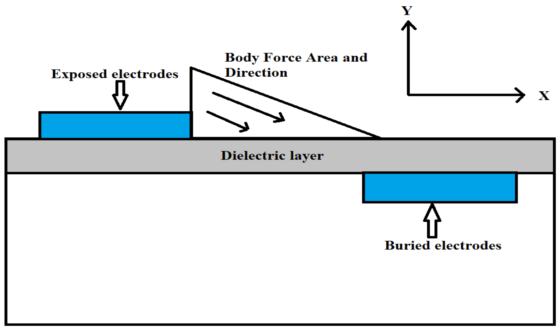
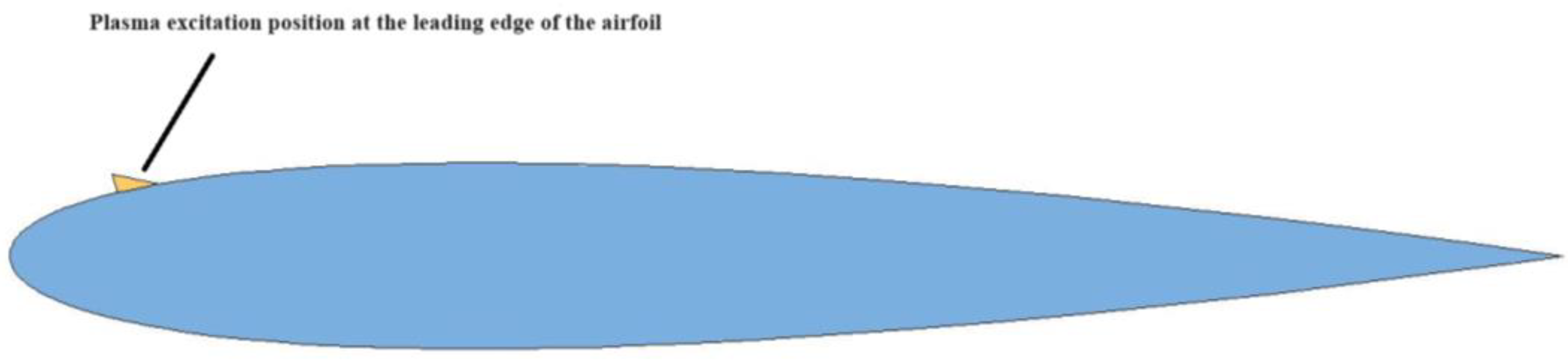
2.3. Mathematical Model of AC DBD Plasma

The plasma discharge excitation is a complex problem involving multiple physical processes and multiple temporal and spatial scales. To accurately analyze the reaction process, a large amount of computational resources is required, which makes the complete resolving of the process impractical. Therefore, a semi-empirical plasma model is commonly adopted in most flow control studies. In this study, the employed numerical model of AC DBD plasma excitation was based on the semi-empirical model developed by Shyy [21], where the impacts of plasma excitation on the flow field are treated as a triangular distribution of volumetric forces. Figure 1 illustrates the distribution of the volumetric forces in the field.
The linearized expression for the electric field strength in the discharge excitation region is given by:
E ¯ = E 0 k 1 x k 2 y
E x = E k 2 k 1 2 + k 2 2 ,   E y = E k 1 k 1 2 + k 2 2
where E 0 = 2.26 × 1 0 7   V / m , and k 1 and k 2 are the gradient constants representing the distribution of the electric field along the x and y directions, respectively ( k 1 = 6.54 × 1 0 9   V / m 2 and k 2 = 1.31 × 10 10   V / m 2 ).
Under the influence of electric field forces, the volume force distribution generated by the collision and transfer of charged particles and neutral molecules in the air can be expressed as:
F t a v e , x = ϑ α δ ρ c e c Δ t E x
F t a v e , y = ϑ α δ ρ c e c Δ t E y
where α = 1 , ϑ = 3   kHz , e c = 1.6 × 10 19   C , Δ t = 67   μ s , ρ c = 1 × 10 17   / m 3 , and δ is the volume force correction parameter, which is determined by the electric field strength in the discharge region:
δ = 0   if   E < E c r
δ = 1   if   E > E c r
where E c r is the breakdown electric field strength.
When the electric field strength in the discharge region is lower than the breakdown electric field strength, the air cannot be ionized to generate plasma. In this case, δ was set to 0. Otherwise, it is set to 1. The volume force generated by the plasma excitation was added as a source term to the solution of the N-S equations. The volume force source term is expressed as:
p i = 0 F x ,   plasam   F y , p l a s m a = 0 c α ϑ ρ c e c Δ t E x c α ϑ ρ c e c Δ t E y
where c is the magnitude parameter of the volume force vector generated by the dielectric barrier discharge plasma excitation blocked through the medium, which is used to represent the strength of the plasma excitation discharge:
c = ρ c e c E r e f L r e f ρ r e f U r e f 2

3. Grid Generation and Numerical Method Validation

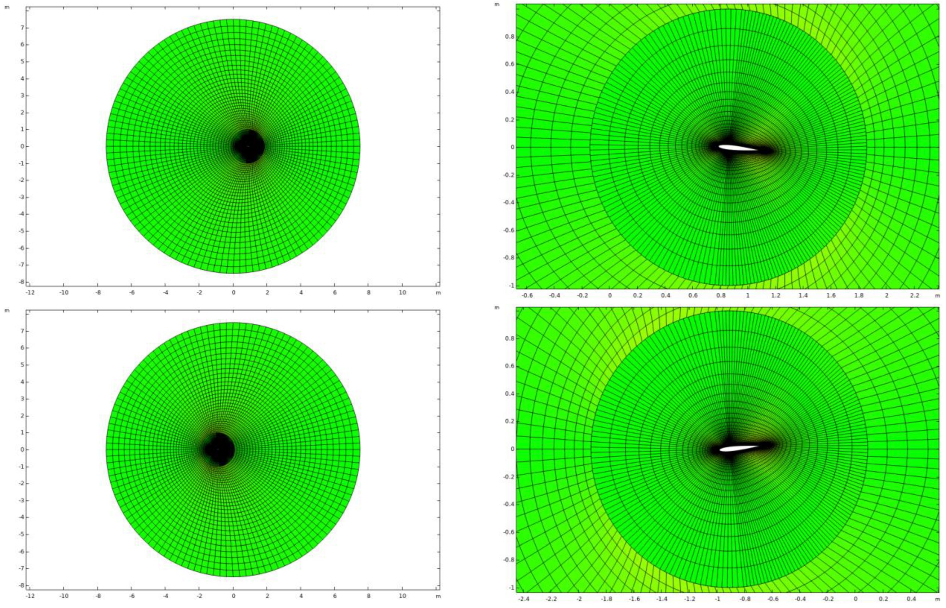
3.1. Grid Generation

In this study, an O-type structured mesh (Figure 2) was employed for the external flow field of the NACA0012 airfoil. It consisted of two domains: the internal pitch and external deformation domains. Encryption treatment was then applied to the plasma excitation positions on the airfoil surface and boundary layer mesh. During the stable operation of the rotor blade profile, the relative incoming flow velocity and angle of attack underwent periodic variations. The periodic variation of the former was simulated by collective deformation to the left and right in the deformation domain. Throughout the process of external structured grid deformation, the interfaces between the internal pitch domains remained connected, and the pitch and deformation domains synchronously moved back and forth to replicate the periodic variation of the incoming flow velocity on the airfoil surface. In addition, within the internal pitch domain, both the mesh and airfoil followed Equation (12) for pitch motion. The center of rotation for the pitch motion of the airfoil was located at 0.25c, and it adhered to the following formula:
α = α a α f × sin ( 2 π f t )
k = f c π / U
where α a is the mean angle of attack, α f is the pitching motion amplitude, k is the reduced frequency, f is the pitching oscillation frequency, c is the chord length of the airfoil, and U is the inflow velocity.
The computational mesh is shown in Figure 2.

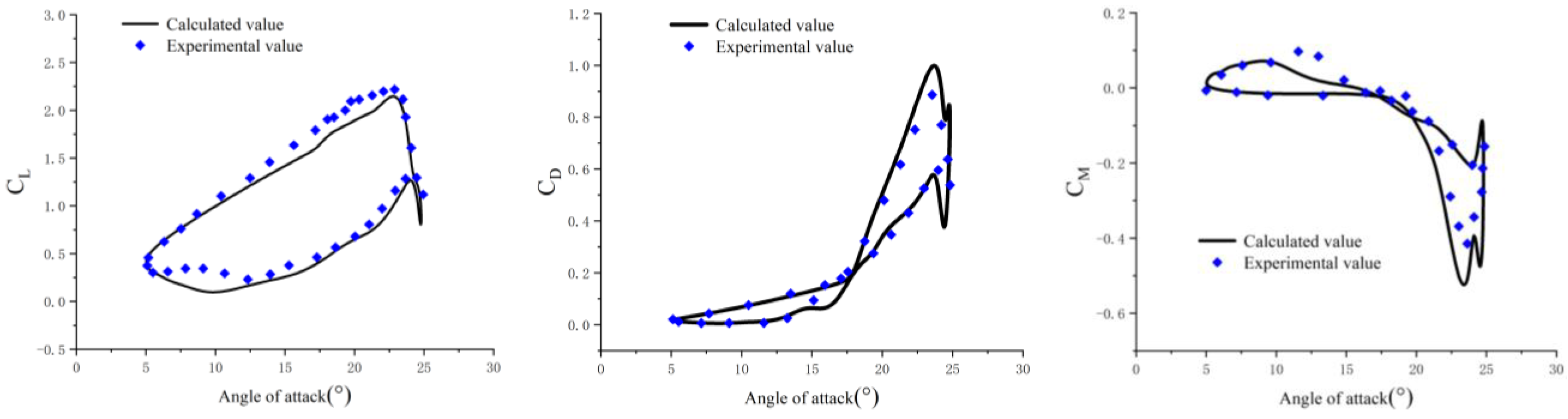
3.2. Validation of the Numerical Simulation Methods

The accuracy of the computational model was first verified. In this study, the NACA0012 airfoil dynamic stall arithmetic case was analyzed and validated based on the SST-k ω turbulence model. The computational conditions included a Mach number of 0.312, a Reynolds number (Re) of 6 × 10 6 , an average angle of attack of 15.12°, a pitch amplitude of 10°, and a reduced frequency of 0.149. Figure 3 shows a comparison between the computed airfoil aerodynamic coefficient and the experimental values [9].
It can be observed that the computed airfoil aerodynamic coefficients and the experimental ones had the same variation trend. The variations in the aerodynamic forces near the stall angle of attack were accurately captured, which demonstrates that the employed numerical simulation model has high accuracy.

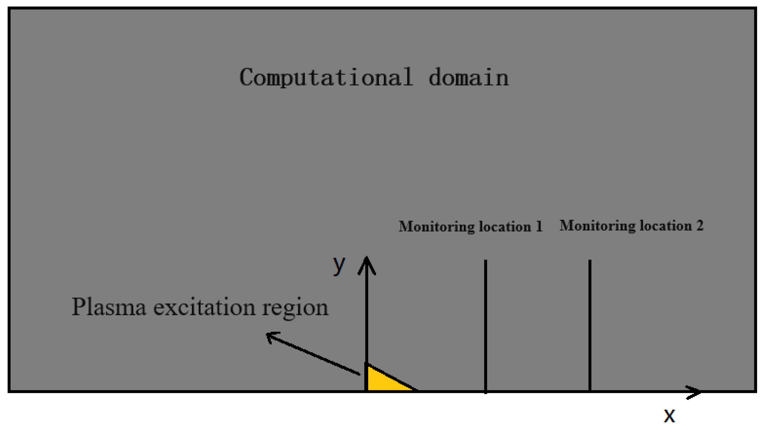
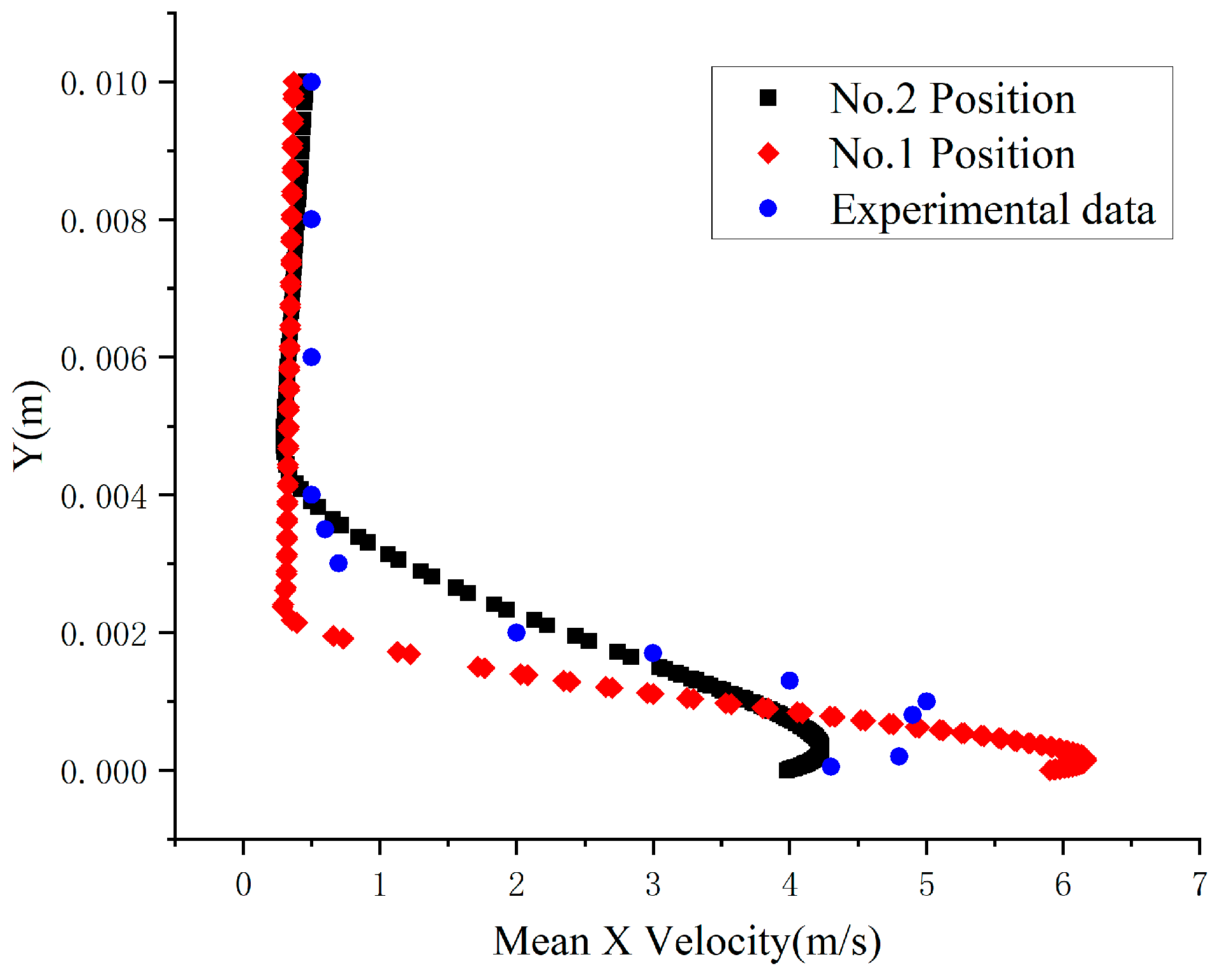
3.3. Validation of the AC DBD Plasma Mathematical Model

In order to validate the developed plasma mathematical model, the discharge process of the plasma in stationary air was simulated. The plasma was placed at the center of the computational domain ( x = 0   cm ), and two monitoring points were placed downstream at x = 1   cm and x = 2   cm to measure the induced jet velocity in the x direction. The overall calculation domain had a height of 12 cm and a length of 20 cm, and the temperature was set to 20 °C. The gas density and viscosity were set to 1.223 × 10 3   kg / m 3 and 1.7895 × 10 5   Pa · s , respectively. To match the peak voltage in the experiment (i.e., V max = 12   kV ), the plasma intensity parameter ( c ) was set to 0.7 during the validation process. In the numerical simulation, the flow field initialization velocity was set to U = 0   m / s . This facilitated the observation of the disturbance effect of the plasma on stationary air. In addition, it allowed for matching the phenomena in the test, which demonstrates the high accuracy of the plasma mathematical model. A schematic of the entire calculation domain is shown in Figure 4.
The computed time-averaged x-direction velocity distributions at the two monitoring points were compared with the measured values in [22]. The obtained results are shown in Figure 5, where the calculated peak-induced jet velocities at positions x = 2   cm and x = 1   cm are 4.1 m/s and 6.2 m/s, respectively. The experimentally measured peak-induced velocity in [22] was 5.3 m/s, which falls between those measured at the two monitoring points. Compared to the position of the experimental peak velocity, the computed peak velocity was closer to the wall. Therefore, it is considered that the developed plasma mathematical model is reasonable.

4. Results and Discussion

In this section, the static stall characteristics of the NACA0012 airfoil under plasma excitation are studied based on the mathematical model of the AC DBD plasma excitation and the numerical simulation method of the airfoil flow field. This allows for analyzing the impacts of the plasma excitation intensity and excitation position on the aerodynamic coefficient of the airfoil. Afterward, considering the aerodynamic environment of the rotor blade profile during rotor operation under variable inflow and angle of attack conditions, the impact of the plasma excitation position on the control of the dynamic stall is studied, and the mechanism of plasma excitation control over dynamic stall is analyzed. The plasma excitation was applied on the upper surface of the airfoil leading edge, as shown in Figure 6.

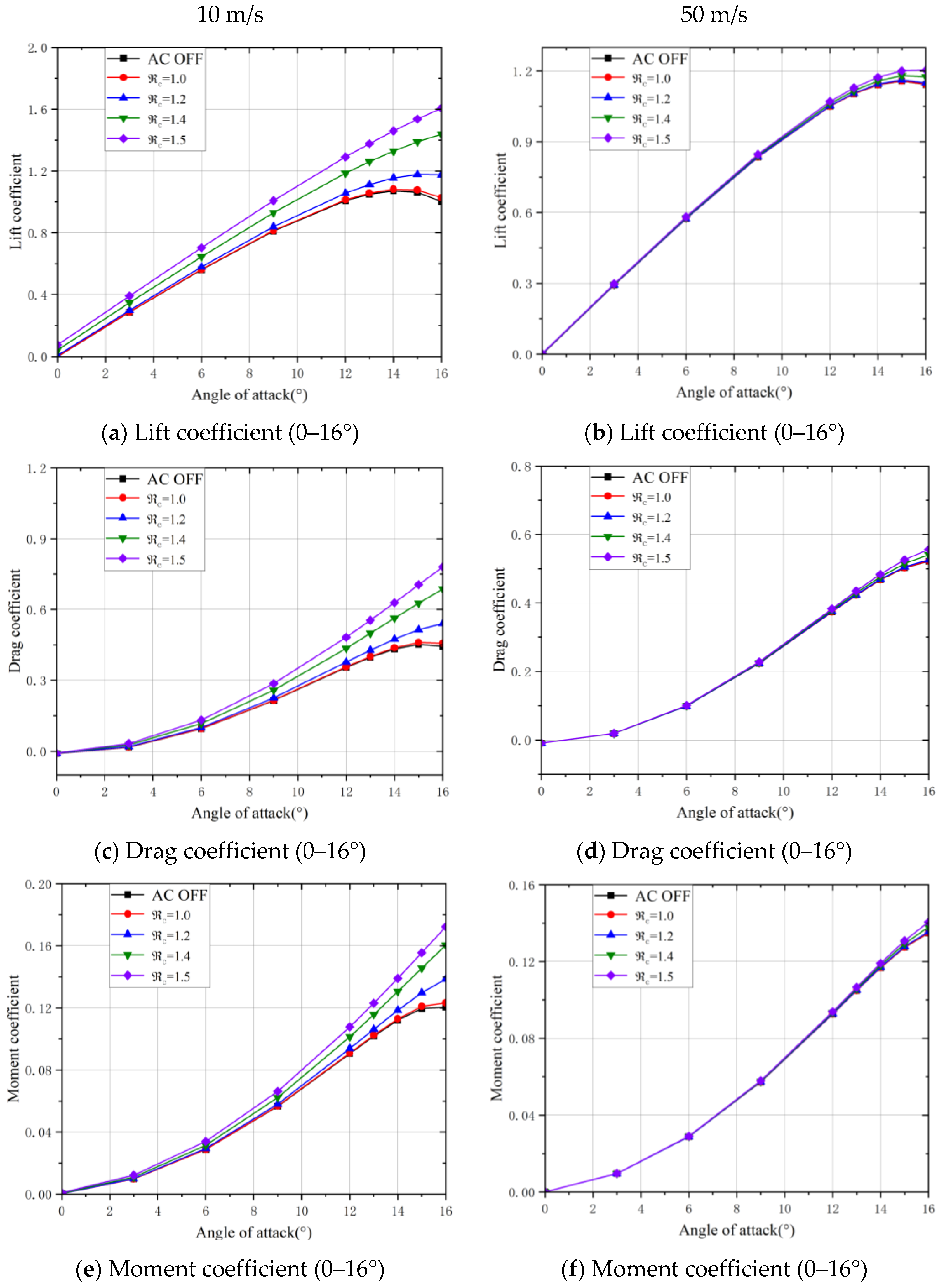
4.1. Impact of the AC DBD Plasma Excitation on the Static Stall Characteristics of Airfoils

The aerodynamic force and moment coefficients of the airfoil under different plasma excitation intensities at various excitation positions were calculated at a constant incoming flow velocity. The freestream velocity and the range of angle of attack for the airfoil were set to 10 m/s and 0–16°, respectively. The plasma excitation was applied on the upper surface of the NACA0012 airfoil at 1.2%c, 4.2%c, 8.4%c, 15.3%c, and 23.7%c from the leading edge, where c is the chord length of the airfoil. The plasma excitation intensity parameters were set to c = 1.0 ,   1.2 ,   1 . 4 ,   1 . 5 . Figure 7 shows the aerodynamic force and moment coefficients of the airfoil calculated under the aforementioned conditions.
It can be seen that, in the absence of plasma excitation, the static stall angle of the NACA0012 airfoil at the incoming flow velocity of 10 m/s was approximately 14°. Before reaching the stall angle, the lift coefficient of the airfoil increased with the increase in the angle of attack, while after reaching it, the lift coefficient started to decrease. When the excitation intensity parameter c was equal to 1, the aerodynamic forces on the airfoil did not significantly change before an angle of attack of 10°, and there was no significant difference between the effects of the excitations at different positions along the leading edge of the airfoil. However, at high angles of attack ranging between 10° and 16°, the plasma excitation slightly increased the lift and moment coefficients of the airfoil. When c was set to 1.4 and 1.5, the plasma excitation had a minor impact on the aerodynamic force coefficients of the airfoil at angles of attack in the range of 0–12°. However, near the stall angle of 14°, the lift, drag, and moment coefficients of the airfoil significantly increased, and the plasma excitation changed the decreasing trend of the lift coefficient, which resulted in significantly increasing the static stall angle of the airfoil. It can also be observed in Figure 7 that the intensity of the plasma excitation was a key factor affecting the control effectiveness. This is due to the fact that a higher intensity within a reasonable range yields a more significant impact on the aerodynamic characteristics of the airfoil. Compared to the excitation intensity, the location of the plasma excitation above the leading edge of the airfoil had a minor impact on the aerodynamic characteristics of the airfoil. Based on the obtained results, applying plasma excitation at a 1.2% chord length from the leading edge on the upper surface of the airfoil had a greater impact on its static stall characteristics.
To study the impact of the plasma excitation on the static aerodynamic characteristics of the NACA0012 airfoil at higher freestream velocity, the latter was increased to 50 m/s, and the location of the plasma excitation was fixed at a 8.4% chord length from the leading edge. Figure 8 shows the impacts of different excitation intensity parameters on the aerodynamic characteristics of the airfoil.
It can be observed that, for an incoming velocity of 50 m/s, the variation of the aerodynamic force coefficients of the airfoil with the applied plasma excitation is small, especially at lower excitation intensities. When c is less than 1.4, the aerodynamic force coefficients of the airfoil remain almost unchanged compared with the case without excitation. More significant aerodynamic force changes can be observed when the intensity reaches 1.4 or 1.5. However, when the incoming flow velocity is 10 m/s, each intensity level of plasma excitation can affect the aerodynamic forces of the airfoil. This is due to the fact that the induced jet velocity generated by AC DBD plasma excitation is limited, and it cannot significantly affect the flow field of the airfoil at higher incoming velocities. As a result, the control effectiveness of AC DBD plasma on static airfoils gradually decreases with the increase of the incoming velocity, which makes the control effects at high-speed conditions difficult to be achieved.

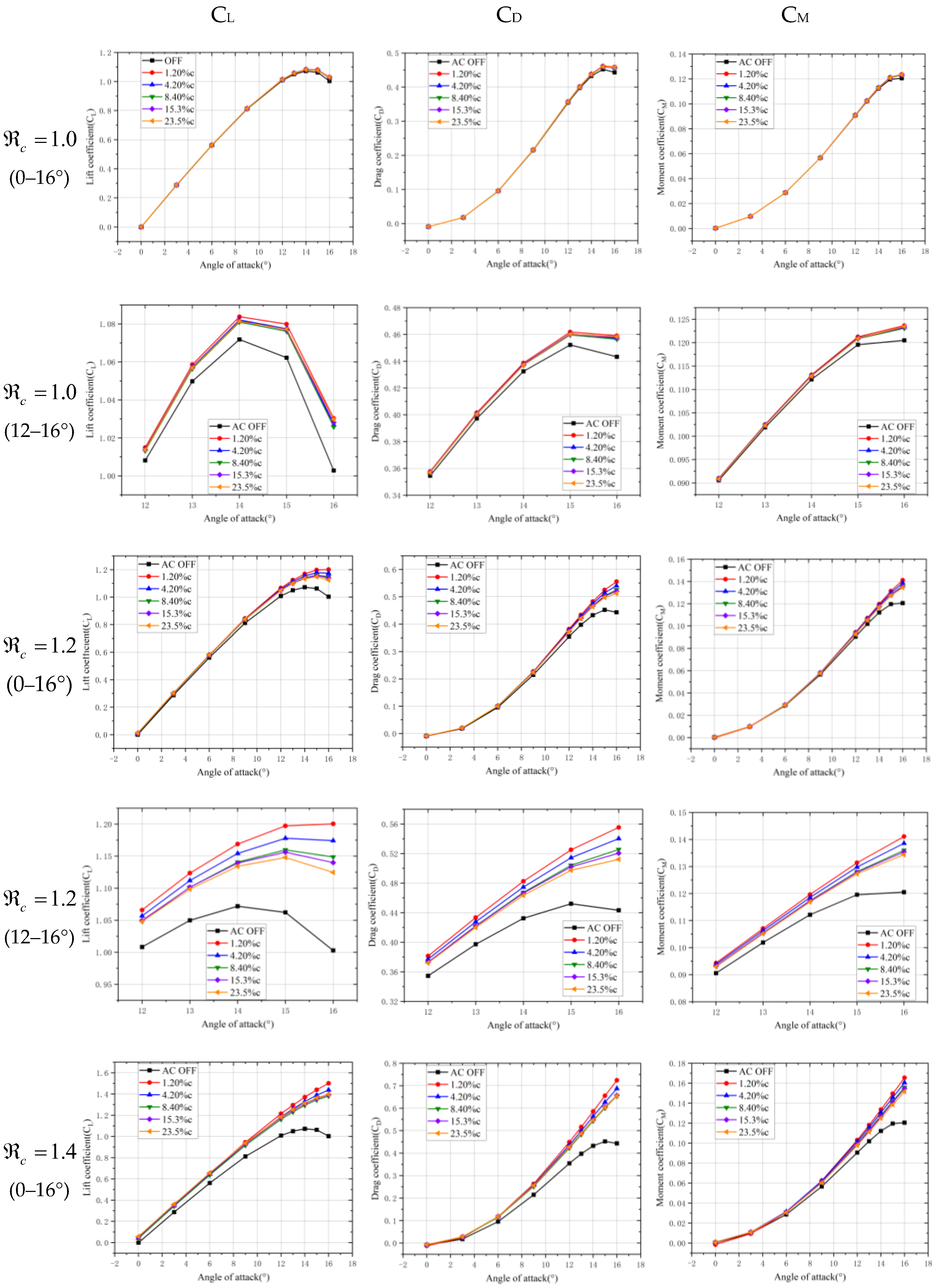
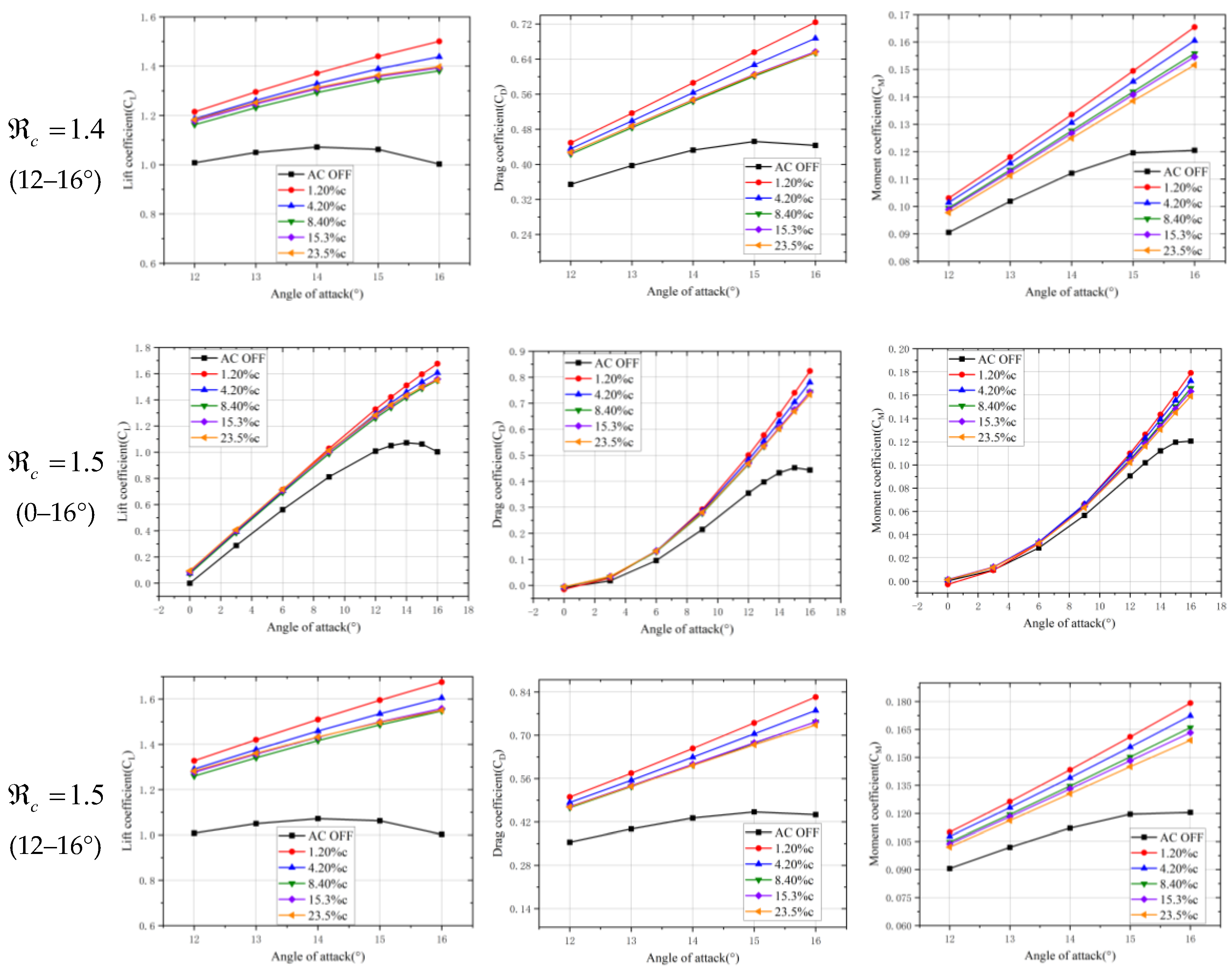
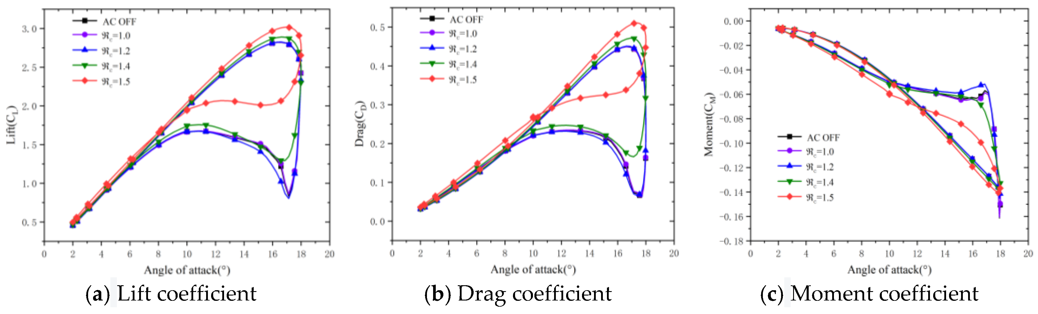
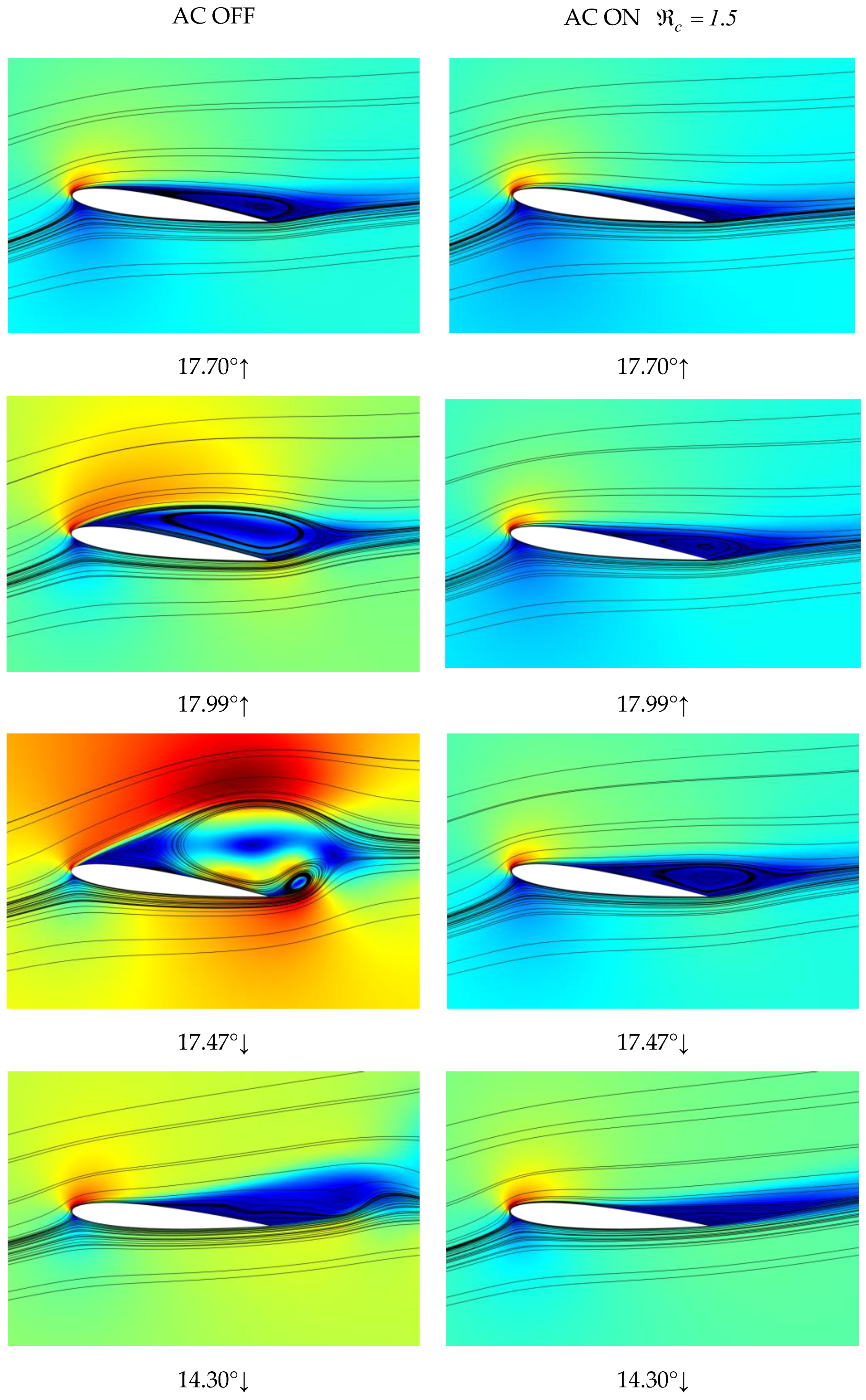
4.2. Impact of the Plasma Excitation Intensity on the Dynamic Stall Characteristics of Airfoils in Constant Incoming Velocity States

This section focuses on studying the influence of the plasma excitation intensity on the control effectiveness of the dynamic stall characteristics of airfoils. The set computational conditions are summarized as follows: average angle of attack of α a = 1 0 , amplitude of pitch angle of α F = 8 , incoming velocity of U = 30   m / s , and reduced frequency of k = 0.0461 . In addition, the plasma excitation was on the upper surface of the airfoil at a distance of 12 % c from the leading edge, and c values of 1, 1.2, 1.4, and 1.5 were used to represent distinct excitation intensities. The obtained results are shown in Figure 9 and Figure 10.
It can be observed in Figure 9 that without plasma excitation, the lift coefficient of the airfoil significantly decreased, and its hysteresis loop area was larger after an angle of attack of 16.5°. For c values of 1 and 1.2, the maximum lift coefficients of the airfoil slightly increased, the hysteresis loop area slightly decreased, and the average drag coefficients slightly increased. When c reached 1.4, the reduction in the hysteresis loop area of the lift coefficient became more prominent. Furthermore, when c reached 1.5, the maximum lift coefficient of the airfoil significantly increased, the hysteresis loop area was significantly reduced, and the phenomenon of stalling was removed. Throughout this process, the average drag coefficient increased, the trend of change in the moment coefficient slowed down, and the significant abrupt aerodynamic changes no longer appeared.
The underlying principle of plasma excitation in suppressing dynamic stall can be clarified by analyzing the streamline near the stall angle of attack (Figure 10). Without plasma excitation, when the airfoil reached the stall angle of attack, a large dynamic stall vortex was formed on the upper surface. The latter migrated from the leading edge toward the trailing edge and eventually shed, which resulted in a significant lift decrease. However, under the plasma excitation with an c of 1.5, no evident dynamic stall vortex was observed on the upper surface near the stall angle of attack. This prevented the sudden lift decrease due to vortex shedding, which allowed for removing the dynamic stall and improving the aerodynamic environment.

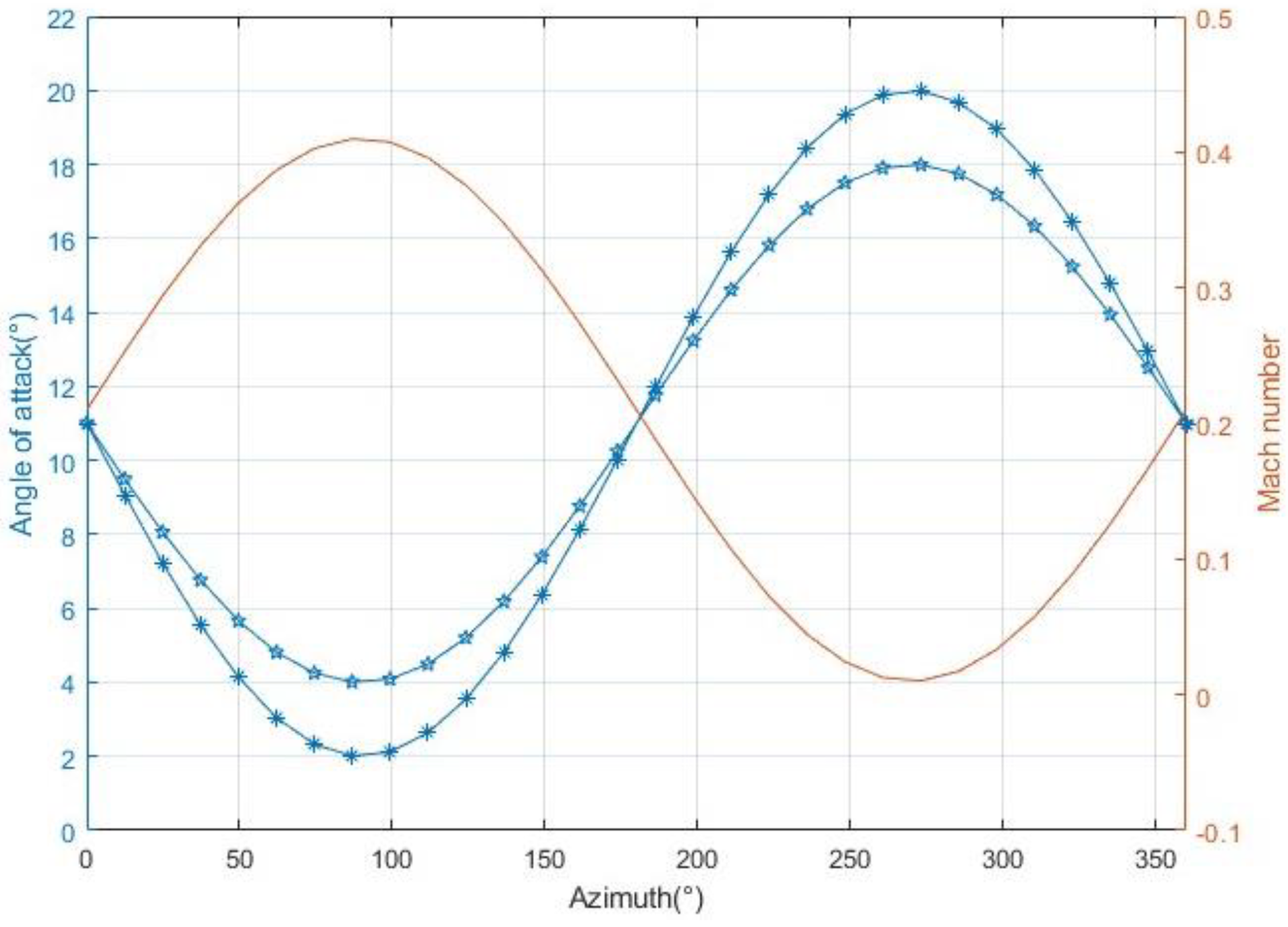
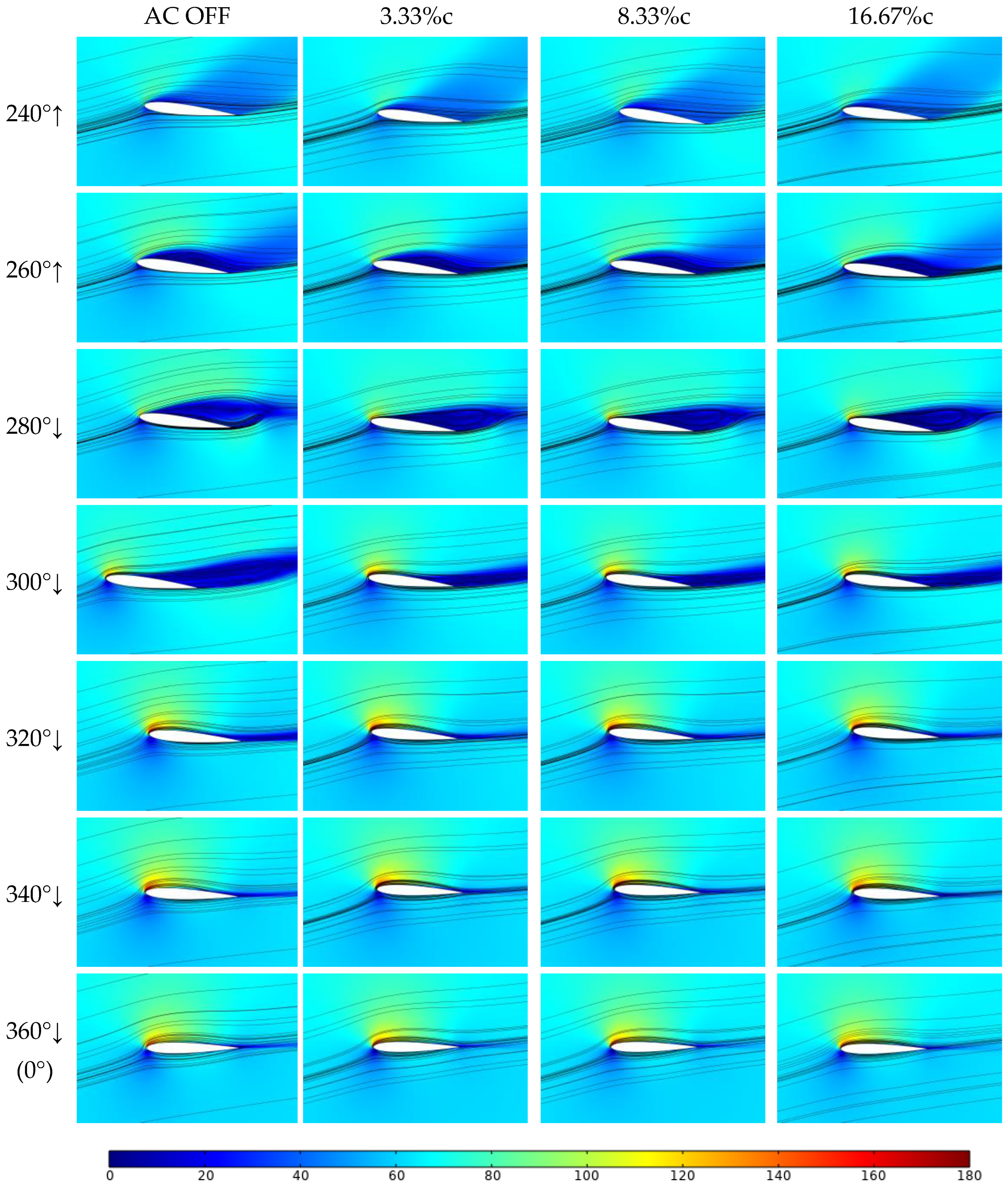
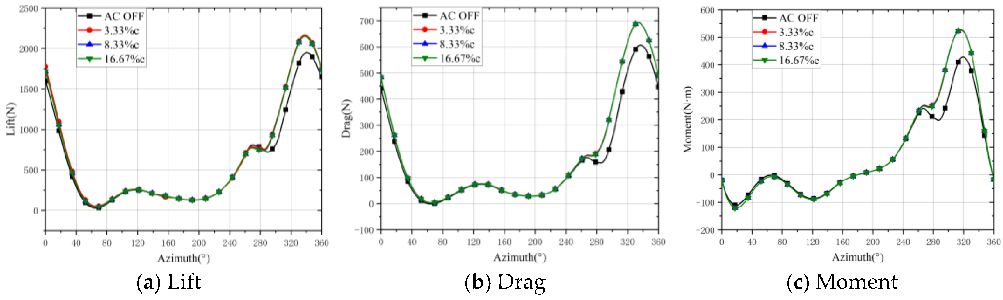
4.3. Impact of the Plasma Excitation on the Dynamic Stall Characteristics of Airfoils in a Variable Incoming Flow Condition

In practical applications, the rotor aerodynamic environment of a helicopter is very complex. However, for a blade profile, the aerodynamic environment can be viewed as varying periodically along the azimuth with the same manipulating inputs and the same flight conditions (Figure 11). In addition, at a given azimuth angle, the angle of attack and incoming flow velocity of the blade element remain unchanged. In this section, far-field grid deformation is employed to simulate the changes of the incoming flow velocity. Moreover, the rotation of the internal pitch domain is used to simulate the variation in the angle of attack in order to accurately simulate a realistic aerodynamic environment.
Considering the rotor of the Z-9 helicopter as an example, with a forward flight speed of 240 km/h and a blade tip Mach number of 0.633, a total pitch of 11° was applied. The airfoil section at 0.3r, where the dynamic stall phenomena is more pronounced, was considered as the object of the study. The underlying airfoil profile was the NACA0012, with an average angle of attack of 11°. The pitch angle values were set to 7° and 9° to represent the mild and deep stall conditions of the rotor, respectively. The relative incoming flow Mach number of the airfoil was 0.21 + 0.2 sin ( k t ) , and the reduced frequency was set to 0.046. Figure 12 illustrates the variation in the angle of attack and the incoming flow for the blade profile based on the working environment of the Z-9 rotor. As previously mentioned, a higher plasma intensity leads to better stall control effects. Therefore, in this section, a plasma model with c = 1.5 is considered. It was installed at three positions along the upper surface leading edge of the airfoil (3.33, 8.33, and 16.67%c) in order to study the influence of the excitation position on the effectiveness of the dynamic stall control.
The control effect of the AC DBD plasma excitation on the mild dynamic stall of the helicopter rotor was first studied. Figure 13 shows the variation in the airfoil lift-to-drag ratio and the pitching moment function of the azimuth angle under mild stall conditions before and after applying plasma excitation at different positions along the leading edge. Figure 14 presents the streamline patterns of the airfoil flow field near the stall angle of attack.
It can be seen in Figure 13a that under the condition of mild stall without plasma excitation (AC OFF), a dynamic stall occurred near the azimuth angle of 270°. The lift suddenly decreased from 750 to 650, while the curves of the drag and pitching moment became smoother in the vicinity of this azimuth angle. It can be observed in the AC OFF column of Figure 14 that at an azimuth angle of 260°, the airfoil continued to pitch up, and a large negative pressure zone appeared on its upper surface, which extended from its leading edge to its trailing edge. At an azimuth angle of 280°, the airfoil started to pitch down, the incoming flow velocity gradually increased, and a large dynamic stall vortex was observed to separate from the trailing edge of the airfoil on its upper surface. In addition, as this dynamic stall vortex detached, the lift, drag, and pitching moment curves returned to their normal trends. It can be observed in the aerodynamic force curve that the plasma excitation applied at three different positions effectively removed the sudden lift drop, drag, and moment hysteresis near the azimuth angle of 270°, and it attenuated the adverse effects of the dynamic stall on the aerodynamic forces. Moreover, turning on the plasma excitation between the azimuth angles of 0° and 260° did not alter the aerodynamic curve of the airfoil. This demonstrates that the plasma excitation had a very slight impact on the aerodynamic characteristics of the airfoil in the normal condition. It can be seen in Figure 14 that without applying the plasma excitation, there was a negative pressure zone with a large width range at the trailing edge of the airfoil at the azimuth angle of 300°. However, when the applied excitation was applied, this negative pressure region became very small, which indicates a significant improvement in the dynamic stall phenomenon.
Applying plasma excitation with c = 1.5 at three different positions above the leading edge of the airfoil under mild stall conditions effectively removed the aerodynamic hysteresis caused by dynamic stall. It can be seen in Figure 14 that under AC DBD plasma excitation, the dynamic stall vortex still underwent generation, movement, and detachment from the upper surface of the airfoil. However, the size of the dynamic stall vortex on the airfoil surface was significantly reduced, and the final stripping was more concentrated near the trailing edge of the airfoil, without causing extensive boundary layer separation. Furthermore, the negative pressure region formed above the airfoil after the detachment of the dynamic stall vortex became smaller. The results of the numerical simulation show that the plasma excitation had a good inhibitory effect on the mild dynamic stall, and the location of the excitation had minimal influence on the control effectiveness.
The large-angle periodic flapping of the blades of a helicopter rotor often leads to its deep stall, which exhibits different aerodynamic characteristics from mild stall. To simulate the condition of deep stall in helicopter rotors, the pitch angle of the airfoil was increased. The aerodynamic force calculations for the airfoil subjected to plasma excitation under deep stall conditions are presented in Figure 15 and Figure 16.
It can be observed in Figure 15 that the rotor airfoil underwent a sudden change in aerodynamic forces near the azimuth angle of 270° in the absence of plasma excitation. In addition, the lift reduction in the deep stall case persisted over a larger azimuthal interval compared to the mild stall case. This also shows that the impact of the deep stall on the aerodynamic force of the airfoil lasted for a longer period over a larger range. The application of plasma excitation had little effect on the aerodynamic force changes before a 270° azimuth angle. Different excitation positions also had minimal impact on the lift curve in deep stall conditions, as the aerodynamic force curves obtained from excitation at various positions largely overlap. There was a slight advance in the angles of attack at which the lift, drag, and moment were restored, and a reduction in the range of abnormal aerodynamic force changes. The maximum lift peak remained largely unchanged. Plasma excitation suppressed the sharp drop in lift and significantly enhanced the airfoil’s maximum lift peak.
It can be observed in the velocity streamline patterns that under deep stall conditions, the negative pressure region on the upper surface of the airfoil near the stall angle was larger than that under mild stall conditions. Similar to the control effect achieved under mild stall conditions, the application of plasma excitation could not remove the generation and evolution of dynamic stall vortices. However, the range of occurrence of dynamic stall vortices on the surface of the airfoil was significantly reduced, and the vortex shedding was more concentrated near its trailing edge, without causing large-scale boundary layer separation. Furthermore, the size of the negative pressure region formed in the vertical direction after the shedding of dynamic stall vortices was also reduced. The results of the numerical simulations demonstrate that, while the AC DBD plasma excitation had a less pronounced control effect on the deep stall conditions than on the mild stall conditions, it still reduced the aerodynamic hysteresis effects caused by stall to a certain extent and removed the adverse impacts of dynamic stall.

5. Conclusions

This paper studies the stall characteristics of a rotor airfoil under AC DBD plasma excitation. A two-dimensional non-uniform mathematical model of plasma distribution was first developed. The impact of plasma excitation on the static stall characteristics of the NACA0012 airfoil was then studied by varying the plasma intensity and the location of excitation on the airfoil. Afterward, the real airflow environment of the rotor blade profile was simulated using deformation mesh and dynamic mesh technology. Different excitation positions of the plasma were explored to analyze the differences in the control effects of mild and deep dynamic stall of the rotor airfoil. The main conclusions that can be drawn from the obtained results are summarized as follows:
(1) In static stall conditions, plasma excitation can increase the stall angle and improve the lift peak of the airfoil. The intensity of the plasma excitation is a key factor affecting the control effect. In addition, within a reasonable range, the greater the intensity of the plasma excitation, the more significant its impact on the aerodynamic characteristics of the airfoil. Compared to the excitation intensity, the impact of the plasma excitation position above the leading edge of the airfoil on its aerodynamic characteristics is relatively small. The velocity of the incoming flow is another important factor affecting the control effect of the AC DBD plasma on static stall. The obtained results show that the impact of plasma excitation on the aerodynamic force of the airfoil at a freestream velocity of 10 m/s was significantly higher than that at 50 m/s.
(2) Under dynamic stall conditions with constant incoming flow velocity, a lower intensity plasma excitation can reduce the magnitude of lift reduction and shorten the duration of the dynamic stall. When the intensity factor reached 1.5, the plasma effectively removed the generation and evolution of dynamic stall vortices and avoided the dynamic stall caused by vortex shedding. This demonstrates that within a certain range, the higher the plasma excitation intensity, the better the control effect over dynamic stall. The plasma excitation mainly works by accelerating the kinetic energy to facilitate the evolution and shedding of dynamic stall vortices, promoting the reattachment of the airflow, inhibiting the flow separation, and improving the aerodynamic characteristics.
(3) Under an aerodynamic environment of a rotor blade profile with variable incoming flow and variable angles of attack, plasma excitation reduced the scale of the dynamic stall vortex during mild stall and effectively removed the occurrence of dynamic stall. In the case of deep stall, the control effect of plasma excitation on dynamic stall was reduced to a certain extent. However, it still helped remove the aerodynamic hysteresis effect caused by dynamic stall and accelerated the recovery of aerodynamic forces. Furthermore, this study found that the position of plasma excitation had a minimal impact on the effectiveness of dynamic stall control.

Author Contributions

The authors confirm contribution to the paper as fol lows: study conception and design: W.K., K.G., Y.L.; data collection: K.G., Y.L.; analysis and interpretation of results: K.G., W.K.; draft manuscript preparation: K.G., W.K. All authors have read and agreed to the published version of the manuscript.

Funding

This research received no external funding.

Data Availability Statement

The data presented in this study are available on request from the corresponding author.

Conflicts of Interest

Author Keyi Guo was employed by the company AVIC Jonhon Optronic Technology Co., Ltd. The remaining authors declare that the research was conducted in the absence of any commercial or financial relationships that could be construed as a potential conflict of interest.

References

  1. Gardner, A.D.; Jones, A.R.; Mulleners, K.; Naughton, J.W.; Smith, M.J. Review of rotating wing dynamic stall: Experiments and flow control. Prog. Aerosp. Sci. 2023, 137, 100887. [Google Scholar] [CrossRef]
  2. Wei, B.; Gao, Y.; Hu, S. Experimental and numerical study on dynamic stall under a large Reynolds number. Adv. Aerodyn. 2023, 5, 16. [Google Scholar] [CrossRef]
  3. Benton, S.I.; Visbal, M.R. The onset of dynamic stall at a high, transitional Reynolds number. J. Fluid Mech. 2019, 861, 860–885. [Google Scholar] [CrossRef]
  4. Corke, T.C.; Thomas, F.O. Dynamic stall in pitching airfoils: Aerodynamic damping and compressibility effects. Annu. Rev. Fluid Mech. 2015, 47, 479–505. [Google Scholar] [CrossRef]
  5. Choudhry, A.; Leknys, R.; Arjomandi, M.; Kelso, R. An insight into the dynamic stall lift characteristics. Exp. Therm. Fluid Sci. 2014, 58, 188–208. [Google Scholar] [CrossRef]
  6. Gupta, R.; Ansell, P.J. Unsteady Flow Physics of Airfoil Dynamic Stall. AIAA J. 2019, 57, 165–175. [Google Scholar] [CrossRef]
  7. Ham, N.D. Aerodynamic loading on a two-dimensional airfoil during dynamic stall. AIAA J. 1968, 6, 1927–1934. [Google Scholar] [CrossRef]
  8. McCroskey, W.J.; McAlister, K.W.; Carr, L.W.; Pucci, S.L. An Experimental Study of Dynamic Stall on Advanced Airfoil Sections. In Volume 1. Summary of the Experiment; NTRS: Washington, DC, USA, 1982. [Google Scholar]
  9. Mcalister, K.W.; Pucci, S.L.; McCroskey, W.J.; Carr, L.W. An Experimental Study of Dynamic Stall on Advanced Airfoil Sections. In Volume 2. Pressure and Force Data; NASA TM-84245; NTRS: Washington, DC, USA, 1982. [Google Scholar]
  10. Kaufmann, K.; Merz, C.B.; Gardner, A.D. Dynamic Stall Simulations on a Pitching Finite Wing. J. Aircr. 2017, 54, 1303–1316. [Google Scholar] [CrossRef]
  11. Gompertz, K.; Jensen, C.D.; Gregory, J.W.; Bons, J.P. Compressible Dynamic Stall Mechanisms Due to Airfoil Pitching and Freestream Mach Oscillations; The Vertical Flight Society: Fairfax, WV, USA, 2012. [Google Scholar]
  12. Hird, K.; Frankhouser, M.W.; Gregory, J.W.; Bons, J.P. Compressible Dynamic Stall of an SSC-A09 Airfoil Subjected to Coupled Pitch and Freestream Mach Oscillations; The Vertical Flight Society: Fairfax, WV, USA, 2014. [Google Scholar]
  13. Hird, K.; Frankhouser, M.W.; Naigle, S.; Gregory, J.W.; Bons, J.P. Study of an SSC-A09 Airfoil in Compressible Dynamic Stall with Freestream Mach Oscillations; The Vertical Flight Society: Fairfax, WV, USA, 2015. [Google Scholar]
  14. Benton, S.I.; Visbal, M.R. Extending the Reynolds number range of high frequency control of dynamic stall. AIAA J. 2019, 57, 2675–2681. [Google Scholar] [CrossRef]
  15. Zha, G.C.; Carroll, B.F.; Paxton, C.D.; Conley, C.A.; Wells, A. High-Performance Airfoil Using Coflow Jet Flow Control. AIAA J. 2005, 45, 2087–2090. [Google Scholar] [CrossRef]
  16. Patel, M.P.; Ng, T.T.; Vasudevan, S.; Corke, T.C.; He, C. Plasma Actuators for Hingeless Aerodynamic Control of an Unmanned Air Vehicle. J. Aircr. 2007, 44, 1264–1274. [Google Scholar] [CrossRef]
  17. Post, M.L.; Corke, T.C. Separation control using plasma actuators: Dynamic stall vortex control on oscillating airfoil. AIAA J. 2006, 44, 3125–3135. [Google Scholar] [CrossRef]
  18. Mitsuo, K.; Watanabe, S.; Atobe, T.; Kato, H.; Tanaka, M.; Uchida, T. Lift Enhancement of a Pitching Airfoil in Dynamic Stall by DBD Plasma Actuators; AIAA-2013–1119; AIAA: Reston, VA, USA, 2013. [Google Scholar]
  19. Li, G.Q.; Zhang, W.G.; Jiang, Y.B.; Pengyu, Y. Experimental investigation of dynamic stall flow control for wind turbine airfoils using a plasma actuator. Energy 2019, 185, 90–101. [Google Scholar]
  20. Sha, J.; Shi, Z.-W.; Chen, Z.; Yao, Z.-Y. Dynamic Stall Control of NACA0012 Airfoil Using AC-DBD Plasma Actuators. Phys. Gases 2021, 6, 50–61. [Google Scholar] [CrossRef]
  21. Shyy, W.; Jayaraman, B.; Andersson, A. Modeling of glow discharge-induced fluid dynamic. J. Appl. Phys. 2002, 92, 6343. [Google Scholar] [CrossRef]
  22. Debiasi, M.; Li, J.M. Experimental study of a DBD-plasma driven channel flow. In Proceedings of the 49th AIAA Aerospace Sciences Meeting Including the New Horizons Forum and Aerospace Exposition, Orlando, FL, USA, 4–7 January 2011. [Google Scholar]
Figure 1. Volume force distribution of the AC DBD plasma discharge excitation.
Aerospace 11 00474 g001
Figure 2. Deforming mesh and dynamic mesh illustration.
Aerospace 11 00474 g002
Figure 3. Aerodynamic coefficients of the airfoil [9].
Aerospace 11 00474 g003
Figure 4. Schematic of the computational domain for the validation of the plasma mathematical model.
Aerospace 11 00474 g004
Figure 5. Verification of the AC DBD plasma model computational results [22].
Aerospace 11 00474 g005
Figure 6. Applying plasma excitation at the leading edge of the airfoil.
Aerospace 11 00474 g006
Figure 7. Aerodynamic coefficients of NACA0012 at different excitation intensities and positions.
Aerospace 11 00474 g007aAerospace 11 00474 g007b
Figure 8. Aerodynamic forces of the airfoil with plasma excitation applied at different freestream velocities.
Aerospace 11 00474 g008
Figure 9. Aerodynamic force coefficients of the airfoil under dynamic stall conditions for different excitation intensities.
Aerospace 11 00474 g009
Figure 10. The streamline near the stall angle of attack of the airfoil before and after plasma excitation.
Aerospace 11 00474 g010
Figure 11. Variations in airfoil angle of attack with azimuth angle.
Aerospace 11 00474 g011
Figure 12. Variation curves of angles of attack and freestream velocity with respect to azimuth angle for airfoil.
Aerospace 11 00474 g012
Figure 13. Aerodynamic forces of mild stall on the airfoil under plasma excitation.
Aerospace 11 00474 g013
Figure 14. The streamline of the airfoil near the azimuth angle of 270° under mild stall conditions.
Aerospace 11 00474 g014
Figure 15. Aerodynamic forces of deep stall on airfoil under plasma excitation.
Aerospace 11 00474 g015
Figure 16. The streamlines of the airfoil near the azimuth angle of 270° under deep stall conditions.
Aerospace 11 00474 g016
Disclaimer/Publisher’s Note: The statements, opinions and data contained in all publications are solely those of the individual author(s) and contributor(s) and not of MDPI and/or the editor(s). MDPI and/or the editor(s) disclaim responsibility for any injury to people or property resulting from any ideas, methods, instructions or products referred to in the content.

