
A Rapid Modeling Method for Airborne FSS Radomes Based on Dynamic Customizable Primitives

Abstract

1. Introduction
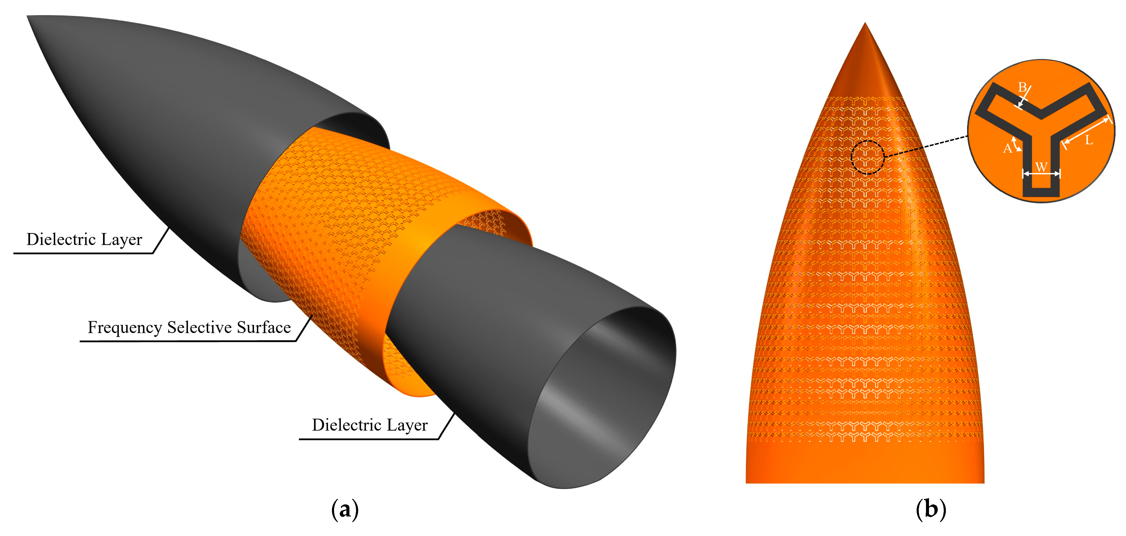
2. Design Idea
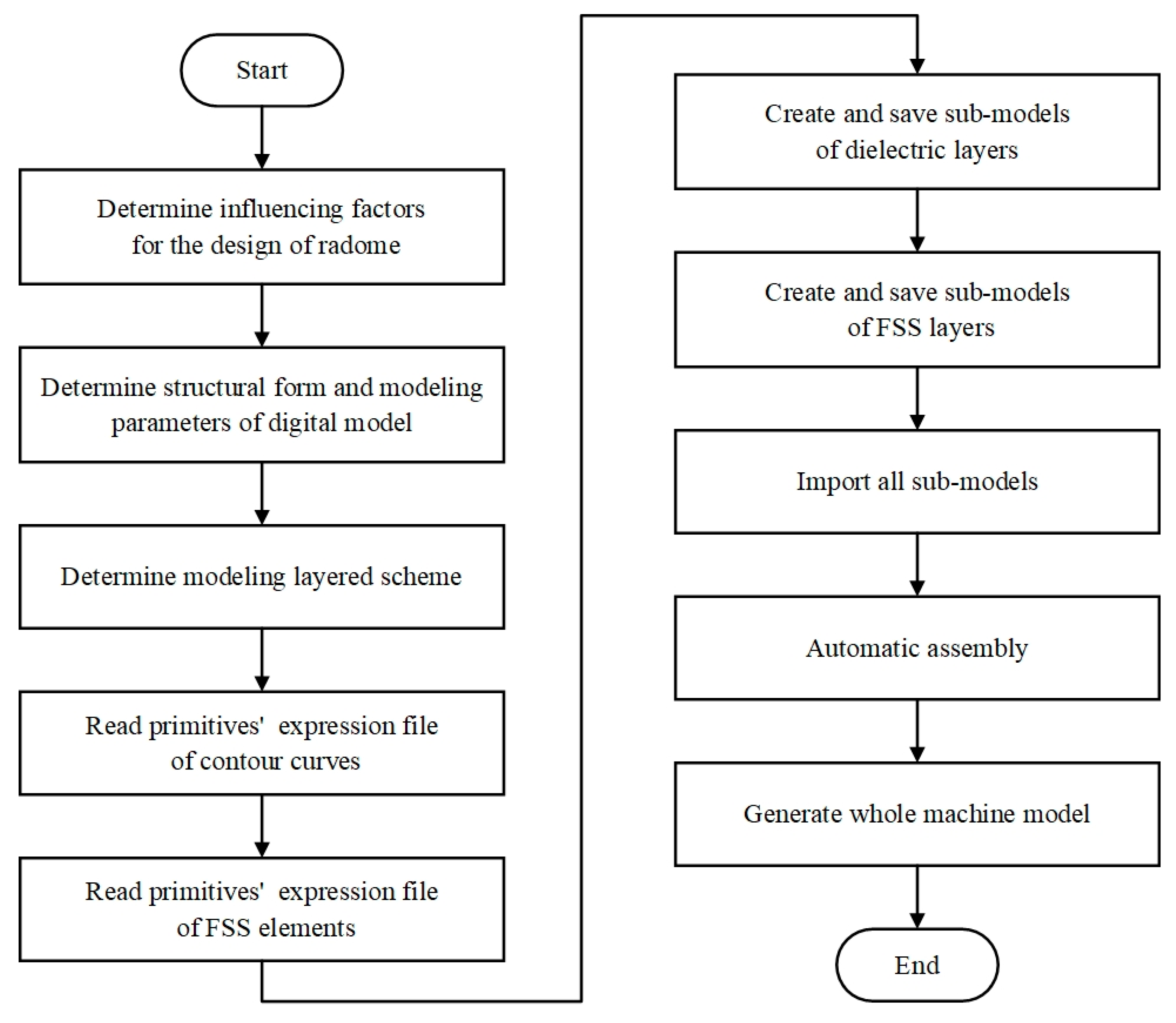
3. Methodology
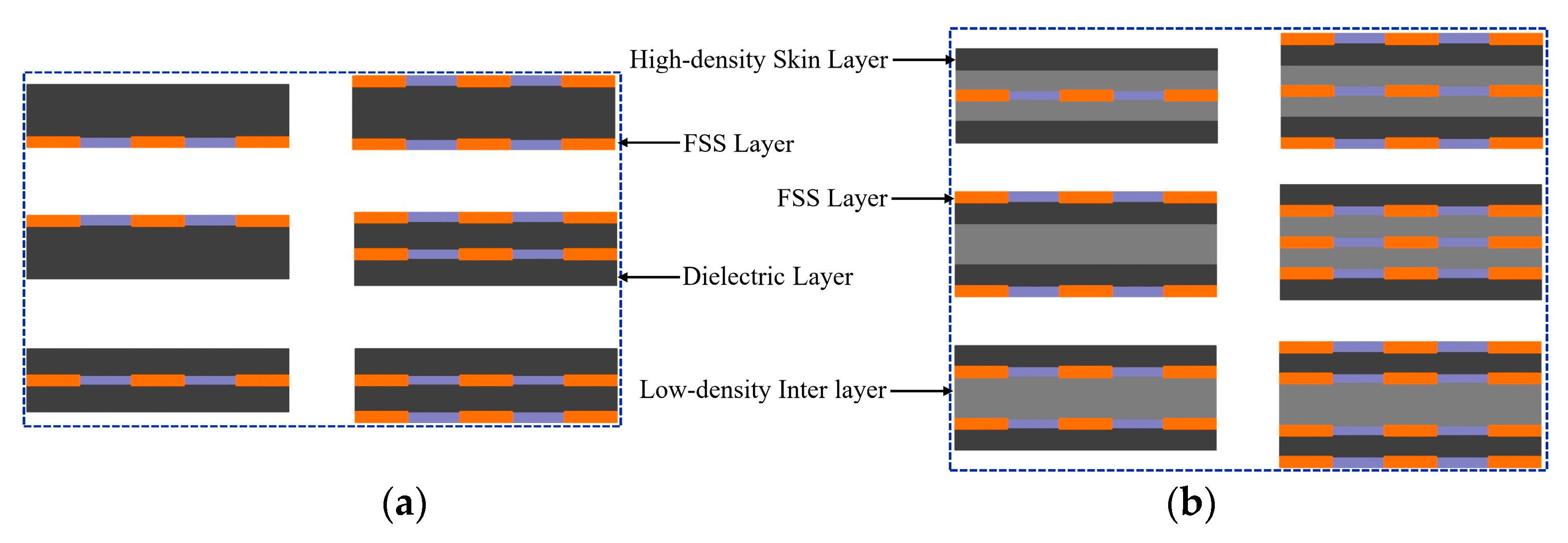
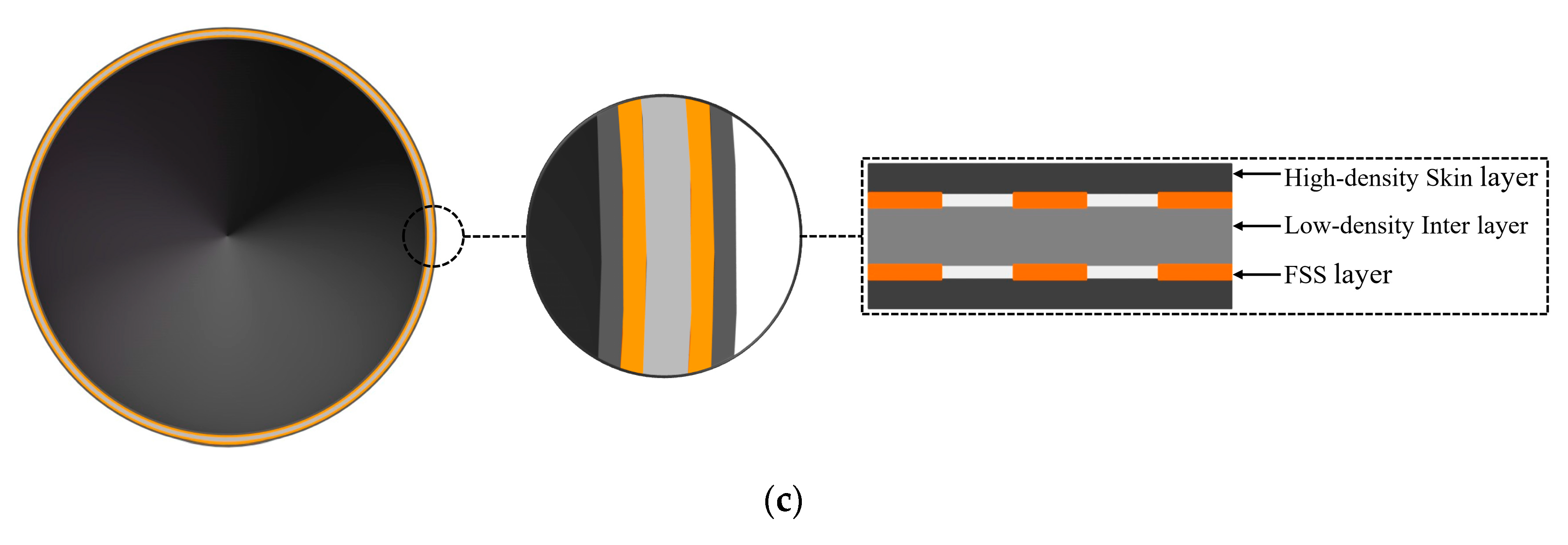
3.1. The Modeling Layered Scheme
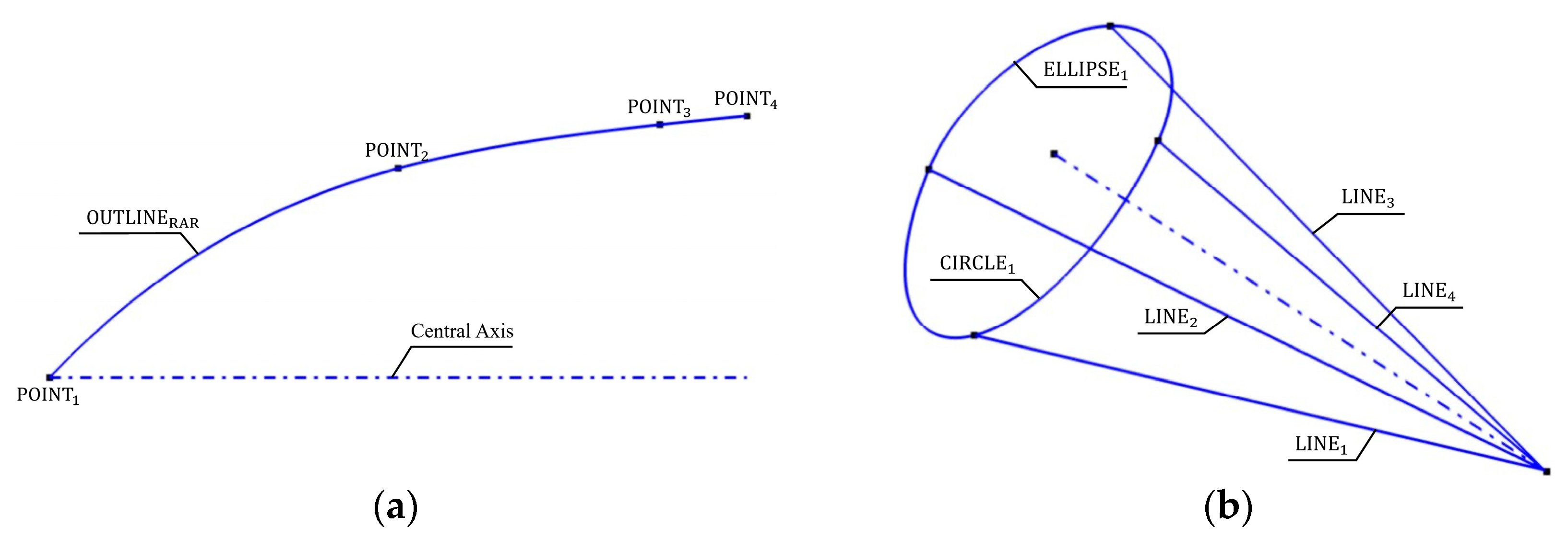
3.2. Expression Rules of Primitives
- Point primitive
- Line primitive
- Circle primitive
- Ellipse primitive
- Spline primitive
3.3. Arrangement Solution for FSS Elements on Undevelopable Surfaces
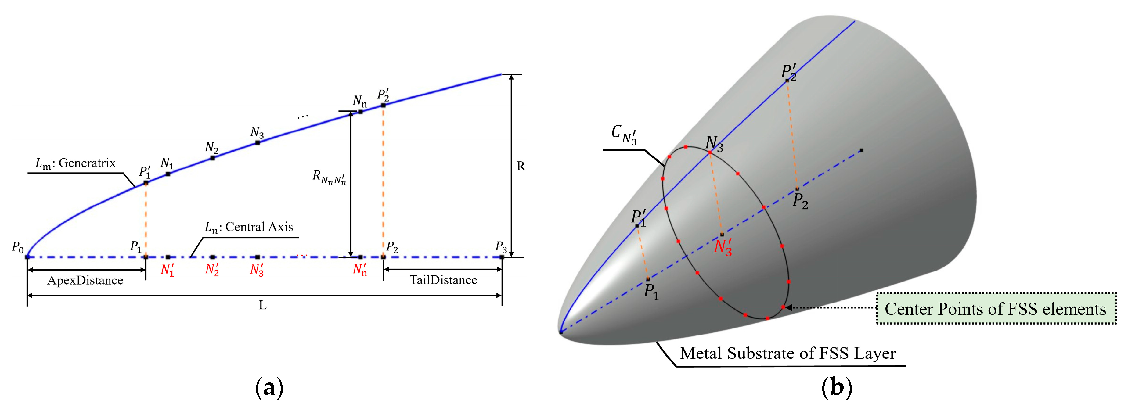
3.3.1. Arrangement Solution of FSS Elements on Rotational Radomes
- 1.
- Arrangement solution of FSS elements along the generatrix
- 2.
- Arrangement solution of FSS elements along latitude circles
3.3.2. Arrangement Solution of FSS Elements on Non-Rotational Radomes
- 3.
- Create a set of isoparametric curves
- 4.
- Arrangement solution of FSS elements along isoparametric curves
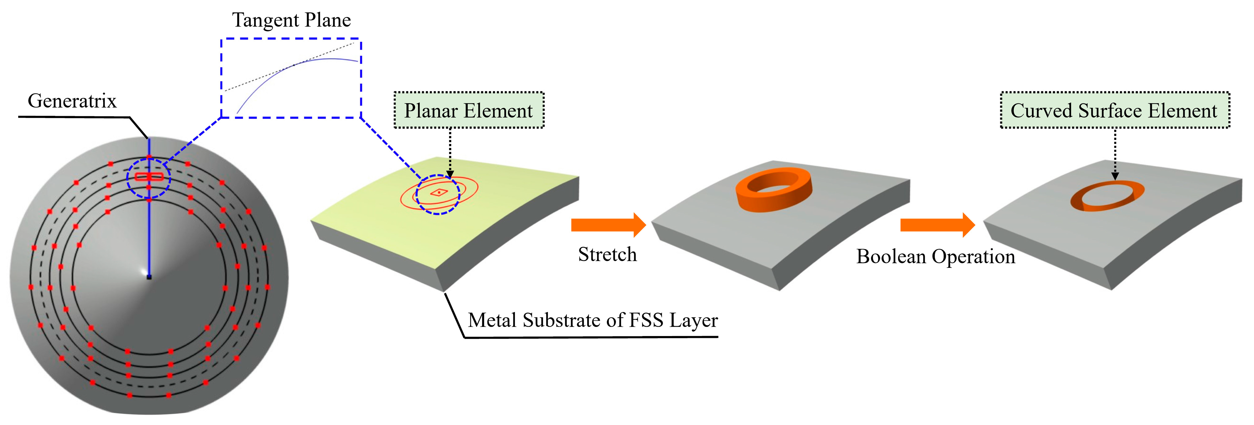
3.4. Mapping Method for FSS Elements
3.5. Implementation of the Sub-Model and the Whole Machine Model
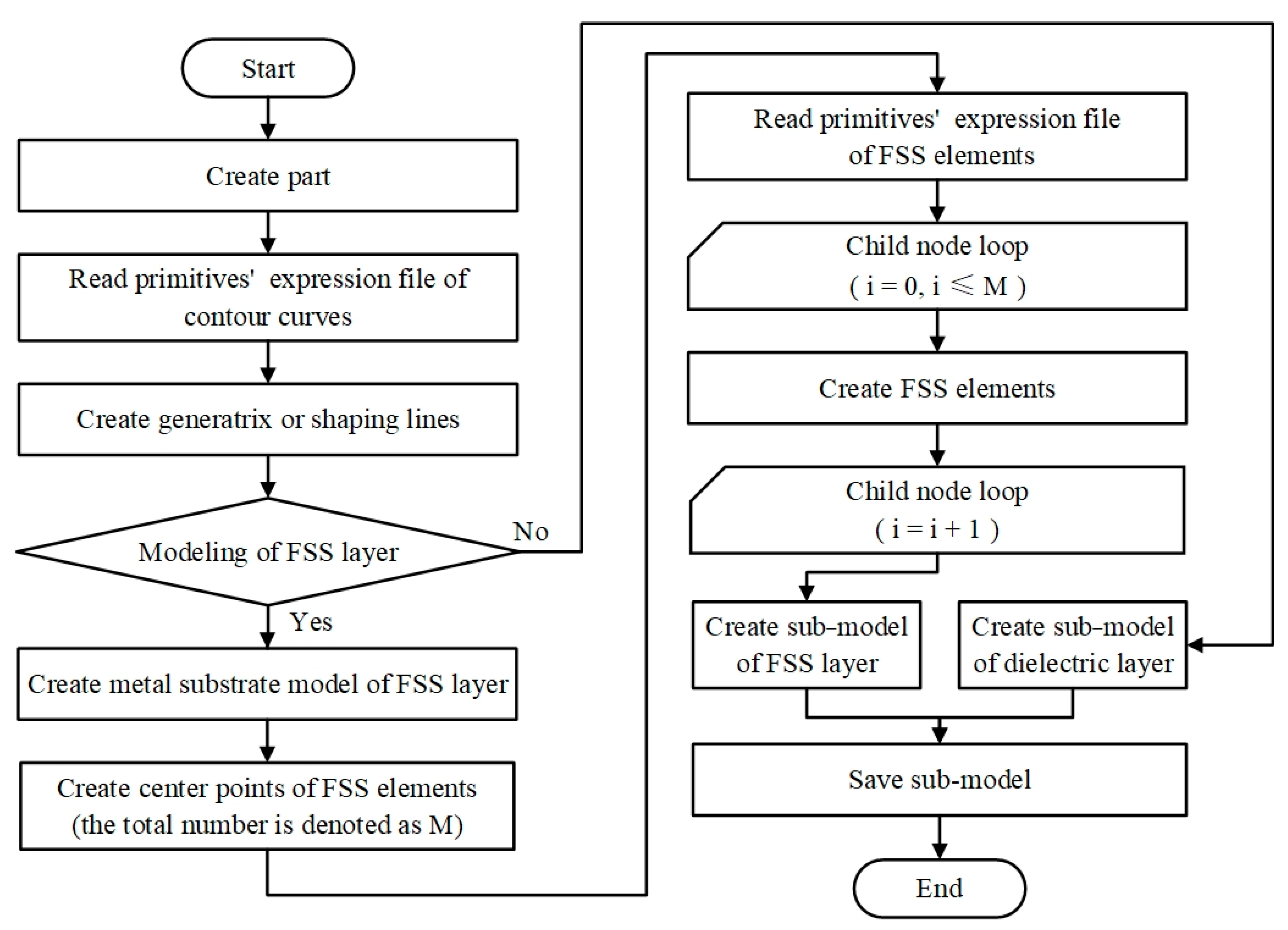
4. System Construction and Example Verification
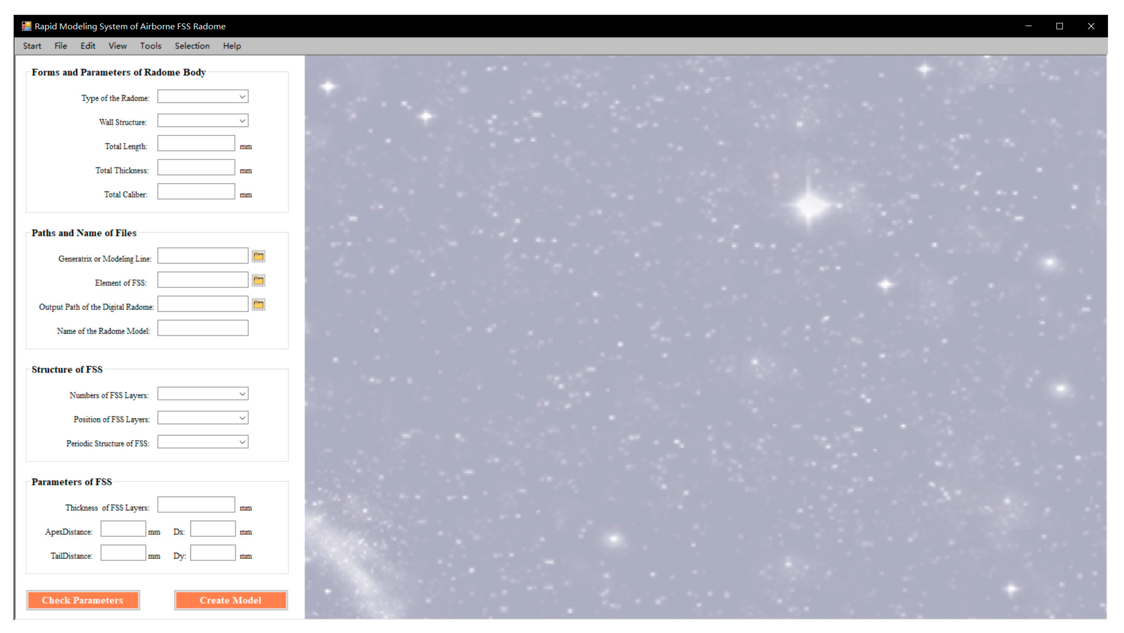
4.1. Construction of a Rapid Modeling System
- 5.
- Modeling preparation phase.
- 6.
- Human–computer interaction phase.
- 7.
- Modeling phase.
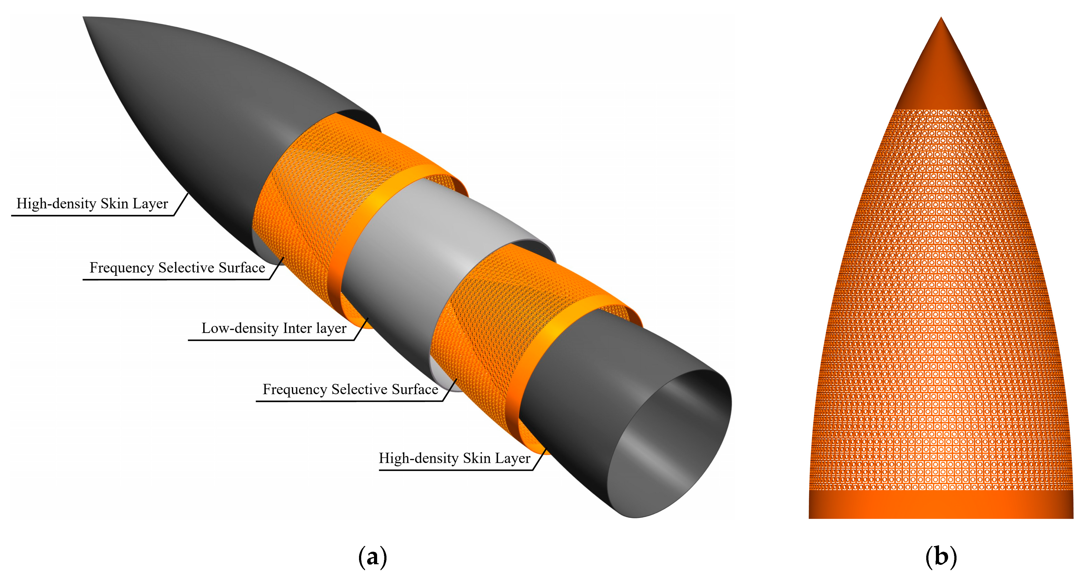
4.2. Demonstration of the Rapid Modeling Effect
4.3. Comparison of Rapid Modeling Efficiency
5. Conclusions
Author Contributions
Funding
Institutional Review Board Statement
Informed Consent Statement
Data Availability Statement
Acknowledgments
Conflicts of Interest
References
- Li, P.; Pedrycz, W.; Xu, W.; Song, L. Far-Field Pattern Tolerance Analysis of the Antenna-Radome System With the Material Thickness Error: An Interval Arithmetic Approach. IEEE Trans. Antennas Propag. 2017, 65, 1934–1946. [Google Scholar] [CrossRef]
- Wei, Z.; Zhou, C.; Zhang, F.; Zhou, C. Reliability Optimization of the Honeycomb Sandwich Structure Based on A Neural Network Surrogate Model. Materials 2023, 16, 7465. [Google Scholar] [CrossRef]
- Kandi, K.K.; Thallapalli, N.; Chilakalapalli, S.P.R. Development of Silicon Nitride-Based Ceramic Radomes—A Review. Int. J. Appl. Ceram. Technol. 2014, 12, 909–920. [Google Scholar] [CrossRef]
- Kenion, T.; Yang, N.; Xu, C. Dielectric and mechanical properties of hypersonic radome materials and metamaterial design: A review. J. Eur. Ceram. Soc. 2022, 42, 1–17. [Google Scholar] [CrossRef]
- Kim, P.C.; Lee, D.G. Composite sandwich constructions for absorbing the electromagnetic waves. Compos. Struct. 2009, 87, 161–167. [Google Scholar] [CrossRef]
- Son, D.-S.; Hyun, J.-M.; Chaki, S.; Park, C.H.; Lee, J.-R. Evaluation of Mechanical/Electromagnetic Preformation of Single-Sided Active Frequency Selective Surface for Stealth Radomes. Int. J. Aeronaut. Space Sci. 2021, 22, 1235–1242. [Google Scholar] [CrossRef]
- Kim, P.; Lee, D.; Seo, I.; Kim, G. Low-observable radomes composed of composite sandwich constructions and frequency selective surfaces. Compos. Sci. Technol. 2008, 68, 2163–2170. [Google Scholar] [CrossRef]
- Wu, K.; Xu, W.; Li, P.; Zhou, J.; Li, W. Miniaturised element frequency selective surface design for high power microwave applications. IET Microw. Antennas Propag. 2023, 17, 846–856. [Google Scholar] [CrossRef]
- Panwar, R.; Lee, J.R. Progress in frequency selective surface-based smart electromagnetic structures: A critical review. Aerosp. Sci. Technol. 2017, 66, 216–234. [Google Scholar] [CrossRef]
- Narayan, S.; Jha, R.M. Electromagnetic Techniques and Design Strategies for FSS Structure Applications [Antenna Applications Corner]. IEEE Antennas Propag. Mag. 2015, 57, 135–158. [Google Scholar] [CrossRef]
- Anwar, R.; Mao, L.; Ning, H. Frequency Selective Surfaces: A Review. Appl. Sci. 2018, 8, 1689. [Google Scholar] [CrossRef]
- Choi, I.; Lee, D.; Lee, D.G. Hybrid composite low-observable radome composed of E-glass/aramid/epoxy composite sandwich construction and frequency selective surface. Compos. Struct. 2014, 117, 98–104. [Google Scholar] [CrossRef]
- Narayan, S.; Gulati, G.; Sangeetha, B.; Nair, R.U. Novel Metamaterial-Element-Based FSS for Airborne Radome Applications. IEEE Trans. Antennas Propag. 2018, 66, 4695–4707. [Google Scholar] [CrossRef]
- Liu, N.; Sheng, X.; Zhang, C.; Fan, J.; Guo, D. Design of FSS radome using binary particle swarm algorithm combined with pixel-overlap technique. J. Electromagn. Waves Appl. 2017, 31, 522–531. [Google Scholar] [CrossRef]
- Rafieipour, H.; Setoodeh, A.; Kin-Tak Lau, A. Mechanical and electromagnetic behavior of fabricated hybrid composite sandwich radome with a new optimized frequency-selective surface. Compos. Struct. 2021, 273, 114256. [Google Scholar] [CrossRef]
- Xu, W.; Duan, B.Y.; Li, P.; Qiu, Y. Study on the Electromagnetic Performance of Inhomogeneous Radomes for Airborne Applications—Part I: Characteristics of Phase Distortion and Boresight Error. IEEE Trans. Antennas Propag. 2017, 65, 3162–3174. [Google Scholar] [CrossRef]
- Nair, R.U.; Jha, R.M. Electromagnetic Design and Performance Analysis of Airborne Radomes: Trends and Perspectives. IEEE Antennas Propag. Mag. 2014, 56, 276–298. [Google Scholar] [CrossRef]
- Wang, Z.; Tang, L.; Zhou, L.; Jiang, Z.; Liu, Z.; Liu, Y. Methodology to Design Variable-Thickness Streamlined Radomes With Graded Dielectric Multilayered Wall. IEEE Trans. Antennas Propag. 2021, 69, 8015–8020. [Google Scholar] [CrossRef]
- Vinisha, C.V.; Mohammed Yazeen, P.S.; Mahima, P.; Joy, V.; Nair, R.U. Multi-layered graded porous radome design for dual-band airborne radar applications. Electron. Lett. 2017, 53, 189–191. [Google Scholar] [CrossRef]
- Xu, W.; Zong, Y.; Li, P.; Qiu, Y. Variable Thickness Airborne Radome Design Considering Thickness Profile Control and Additional Electromagnetic Performance. IEEE Trans. Antennas Propag. 2021, 69, 2443–2448. [Google Scholar] [CrossRef]
- Xu, W.; Duan, B.Y.; Li, P.; Qiu, Y. A New Efficient Thickness Profile Design Method for Streamlined Airborne Radomes. IEEE Trans. Antennas Propag. 2017, 65, 6190–6195. [Google Scholar] [CrossRef]
- Xu, W.; Duan, B.Y.; Li, P.; Qiu, Y. Study on the Electromagnetic Performance of Inhomogeneous Radomes for Airborne Applications—Part II: The Overall Comparison With Variable Thickness Radomes. IEEE Trans. Antennas Propag. 2017, 65, 3175–3183. [Google Scholar] [CrossRef]
- de Lucena Nóbrega, C.; Ribeiro da Silva, M.; da Fonseca Silva, P.H.; D’Assunção, A.G. A compact frequency selective surface with angular stability based on the Sierpinski fractal geometry. J. Electromagn. Waves Appl. 2013, 27, 2308–2316. [Google Scholar] [CrossRef]
- Murugasamy, L.; Sivasamy, R. A Novel Fractal Inspired Iterated Four-Legged Loaded Loop Elements Based 2.5-D Miniaturized Frequency Selective Surface. IEEE Trans. Electromagn. Compat. 2021, 63, 2164–2167. [Google Scholar] [CrossRef]
- Yang, Z.; Luo, F.; Zhou, W.; Jia, H.; Zhu, D. Design of a thin and broadband microwave absorber using double layer frequency selective surface. J. Alloys Compd. 2017, 699, 534–539. [Google Scholar] [CrossRef]
- Solunke, Y.; Kothari, A. An ultra-thin, low-RCS, dual-bandpass novel fractal-FSS for planar/conformal C&X bands applications. AEU-Int. J. Electron. Commun. 2024, 175, 155073. [Google Scholar] [CrossRef]
- Sheng, X.; Wang, H.; Liu, N.; Wang, K. A Conformal Miniaturized Bandpass Frequency-Selective Surface With Stable Frequency Response for Radome Applications. IEEE Trans. Antennas Propag. 2024, 72, 2423–2433. [Google Scholar] [CrossRef]
- Grendysa, W.; Joël, J.; Emmanuel, B. Parametric model of aircraft external geometry as a component of FAST-OAD aircraft preliminary design system. J. Phys. Conf. Ser. 2023, 2526, 012030. [Google Scholar] [CrossRef]
- Ma, L.; Zhang, Q.J.; Liu, W.; Zhang, J. Advances in hybrid format-based neuro-transfer function techniques for parametric modeling of microwave components. Int. J. Numer. Model. Electron. Netw. Devices Fields 2023, 37, e3122. [Google Scholar] [CrossRef]
- Chen, L.; Zhang, L.; Wu, Y.; Xu, G.; Li, B. Isogeometric Size Optimization Design Based on Parameterized Volume Parametric Models. Comput. Aided Des. 2024, 169, 103672. [Google Scholar] [CrossRef]
- Zheng, L.; Chen, S.; Ji, S.; Chen, Z. An improved parametric model for marine propeller: iPM4MP. Ocean Eng. 2023, 287, 115712. [Google Scholar] [CrossRef]
- Tang, Z.; Zou, Q.; Gao, S. A decision-support method for multi-parameter editing of parametric CAD models. Adv. Eng. Inform. 2023, 56, 101997. [Google Scholar] [CrossRef]
- Saeedi Heydari, M.; Ghezavati, J.; Abbasgholipour, M.; Mohammadi Alasti, B. Various types of ceramics used in radome: A review. Sci. Iran. 2017, 24, 1136–1147. [Google Scholar] [CrossRef]
- Wang, Q.; Li, P.; Rocca, P.; Li, R.; Tan, G.; Hu, N.; Xu, W. Interval-Based Tolerance Analysis Method for Petal Reflector Antenna With Random Surface and Deployment Errors. IEEE Trans. Antennas Propag. 2023, 71, 8556–8569. [Google Scholar] [CrossRef]
- Ding, G.; Anselmi, N.; Xu, W.; Li, P.; Rocca, P. Interval-Bounded Optimal Power Pattern Synthesis of Array Antenna Excitations Robust to Mutual Coupling. IEEE Antennas Wirel. Propag. Lett. 2023, 22, 2725–2729. [Google Scholar] [CrossRef]
- Nag, A.; Rao, R.R.; Panda, P.K. High temperature ceramic radomes (HTCR)—A review. Ceram. Int. 2021, 47, 20793–20806. [Google Scholar] [CrossRef]
- Yang, J.; Zheng, H.; Pang, Y.; Qu, B.; Li, Y.; Wang, J.; Xu, Z. Design, modelling, and manufacturing of sandwich radome structure with out-of-band absorption and in-band transmission performances. Compos. Struct. 2024, 339, 118138. [Google Scholar] [CrossRef]
- Chen, X.Y.; Feng, Y.W.; Song, Z.C.; Zhou, C.P. Mechanical property analysis and experimental validation of composite honeycomb sandwich radome considering perforation and impact damage. Conf. Ser. 2024, 2746, 012048. [Google Scholar] [CrossRef]
- Hao, L.; Gang, Q.; Wang, X.; Wang, K.; Zheng, Y. Study on Shear Fatigue Performance of Scarf Repaired Honeycomb Sandwich Structure. J. Phys. Conf. Ser. 2024, 2671, 012014. [Google Scholar] [CrossRef]
- Zhou, L.; Wang, P.; Pei, Y.; Zeng, A.; Tang, L.; Liu, Z.; Liu, Y.; Jiang, Z.; Fang, D. Design and characterization for dual-band and multi-band A-sandwich composite radome walls. Compos. Sci. Technol. 2017, 149, 28–33. [Google Scholar] [CrossRef]
- Jin, L.; Zhao, Y.; Chen, C.; Zhang, J.; He, Y.; Yin, C.; Wu, N.; Tang, J.; Xing, S. Application, development, and challenges of stealth materials/structures in next-generation aviation equipment. Appl. Surf. Sci. Adv. 2024, 19, 100575. [Google Scholar] [CrossRef]
- Venkatesh, G.; Singh, S.P.; Thottappan, M. A novel fast roll-off bandpass frequency selective surface for stealth applications. J. Electromagn. Waves Appl. 2024, 38, 571–581. [Google Scholar] [CrossRef]


| Parameter | Value | Parameter | Value |
|---|---|---|---|
| structural form | rotational | 150 mm | |
| wall structure | A-sandwich | 50 mm | |
| total length | 800 mm | numbers of FSS layers | two-layer |
| total thickness | 12 mm | position of FSS layers | skin-core junction |
| total caliber | 400 mm | periodic structure of FSS | aperture |
| thickness of FSS layers | 2 mm | 12 mm | |
| thickness of skin layers | 2 mm | 12 mm | |
| thickness of inter layer | 4 mm | numbers of FSS elements | 8589 |
| Parameter | Value | Parameter | Value |
|---|---|---|---|
| structural form | non-rotational | 100 mm | |
| wall structure | solid-core | 50 mm | |
| total length | 400 mm | periodic structure of FSS | patch |
| total thickness | 6 mm | type of FSS elements | ring-shaped |
| total caliber | 250 mm | size of FSS elements | R6.5 mm × R4 mm |
| thickness of FSS layers | 2 mm | 15 mm | |
| numbers of FSS layers | one-layer | 15 mm | |
| position of FSS layers | middle | numbers of FSS elements | 530 |
| Parameter | Value | Parameter | Value |
|---|---|---|---|
| structural form | rotational | 100 mm | |
| wall structure | solid-core | 50 mm | |
| total length | 600 mm | periodic structure of FSS | aperture |
| total thickness | 6 mm | type of FSS elements | Y-ring-shaped |
| total caliber | 300 mm | size of FSS elements | L6 mm × W4 mm × B1 mm × A60° |
| thickness of FSS layers | 2 mm | 15 mm | |
| numbers of FSS layers | one-layer | 14 mm | |
| position of FSS layers | middle | numbers of FSS elements | 1582 |
| Manual Methods | HFSS-MATLAB Combined Method | Method Described in This Paper | |
|---|---|---|---|
| Model A | ≥300 min | ≥180 min | ≤15 min |
| Model B | ≥180 min | ≥40 min | ≤8 min |
| Model C | ≥120 min | ≥20 min | ≤3 min |
Disclaimer/Publisher’s Note: The statements, opinions and data contained in all publications are solely those of the individual author(s) and contributor(s) and not of MDPI and/or the editor(s). MDPI and/or the editor(s) disclaim responsibility for any injury to people or property resulting from any ideas, methods, instructions or products referred to in the content. |
© 2024 by the authors. Licensee MDPI, Basel, Switzerland. This article is an open access article distributed under the terms and conditions of the Creative Commons Attribution (CC BY) license (https://creativecommons.org/licenses/by/4.0/).
Share and Cite
Qiu, C.; Li, S.; Zhang, W.; Song, L.; Li, X.; Yan, Z.; Chen, Y.; Suo, S. A Rapid Modeling Method for Airborne FSS Radomes Based on Dynamic Customizable Primitives. Aerospace 2024, 11, 505. https://doi.org/10.3390/aerospace11070505
Qiu C, Li S, Zhang W, Song L, Li X, Yan Z, Chen Y, Suo S. A Rapid Modeling Method for Airborne FSS Radomes Based on Dynamic Customizable Primitives. Aerospace. 2024; 11(7):505. https://doi.org/10.3390/aerospace11070505
Chicago/Turabian StyleQiu, Cunai, Shen Li, Wenwu Zhang, Liwei Song, Xiang Li, Zhongen Yan, Yue Chen, and Saisai Suo. 2024. "A Rapid Modeling Method for Airborne FSS Radomes Based on Dynamic Customizable Primitives" Aerospace 11, no. 7: 505. https://doi.org/10.3390/aerospace11070505
APA StyleQiu, C., Li, S., Zhang, W., Song, L., Li, X., Yan, Z., Chen, Y., & Suo, S. (2024). A Rapid Modeling Method for Airborne FSS Radomes Based on Dynamic Customizable Primitives. Aerospace, 11(7), 505. https://doi.org/10.3390/aerospace11070505