_Zhu.png)
Design of an Automatic Sealing Mechanism for Extraterrestrial Sample-Collecting Robot

 ,
,
Abstract
:1. Introduction
2. Robotic System Design
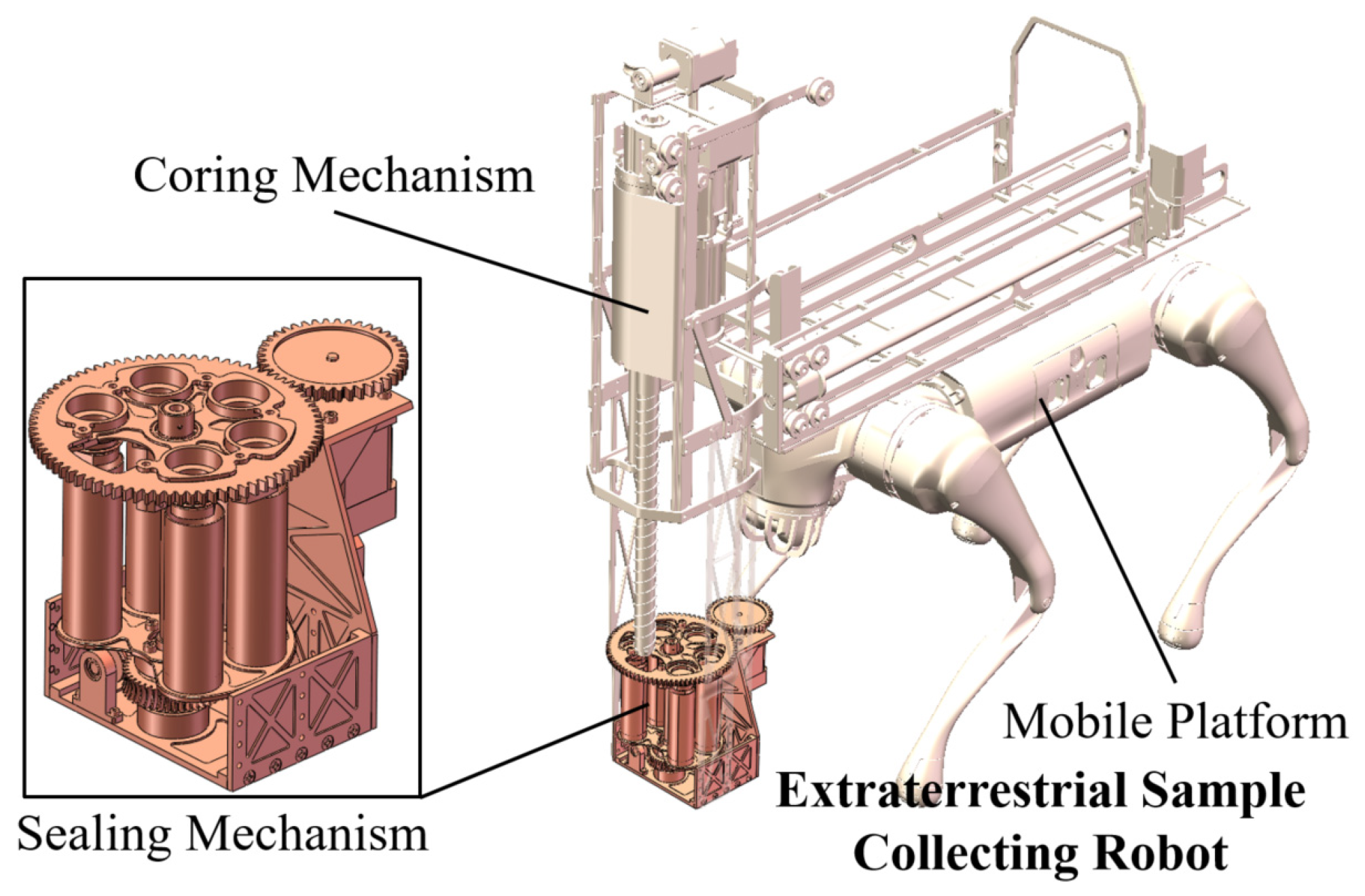
2.1. System Description
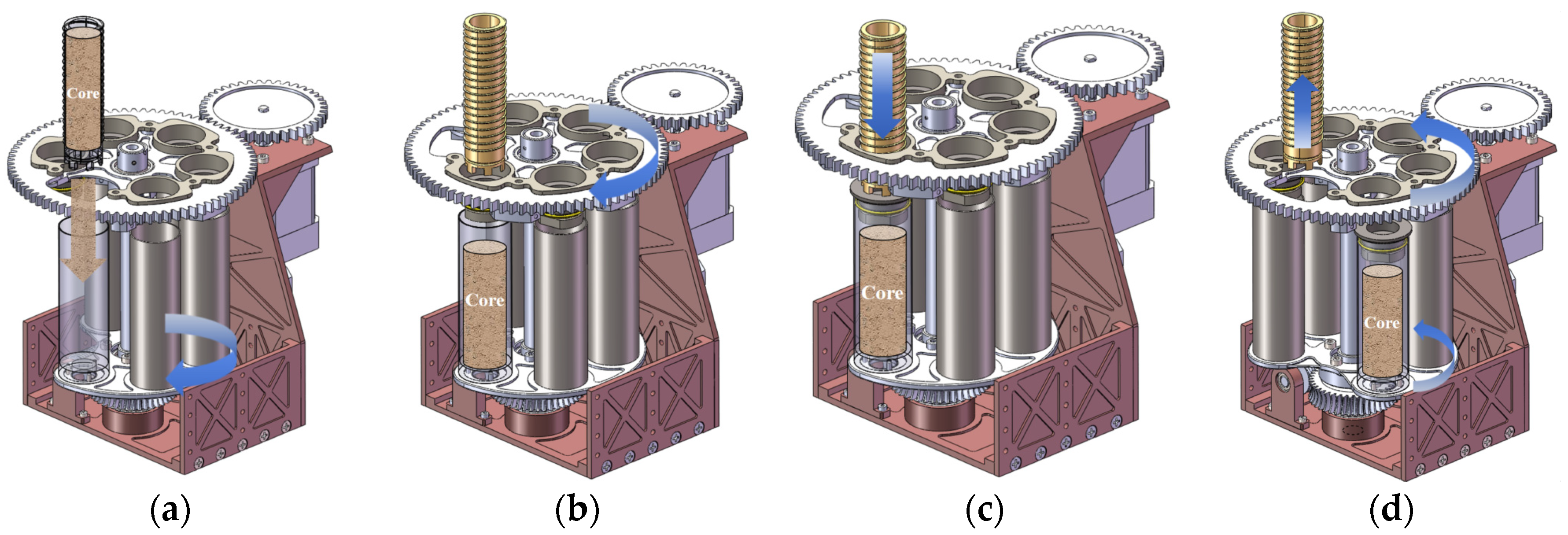
2.2. System Workflow
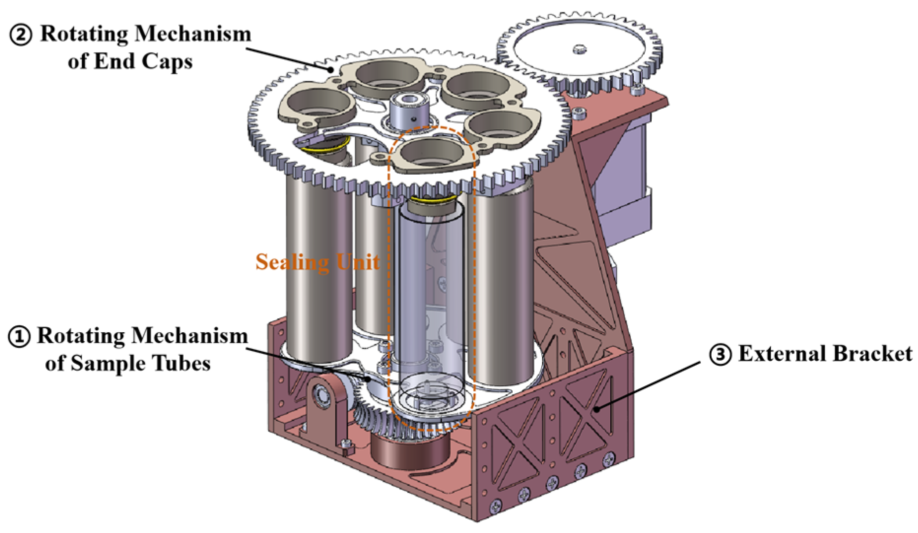
2.3. Sealing Mechanism Design
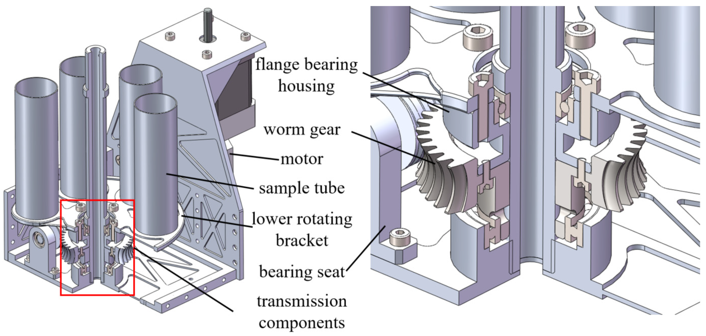
2.3.1. Rotating Mechanism of Sample Tubes
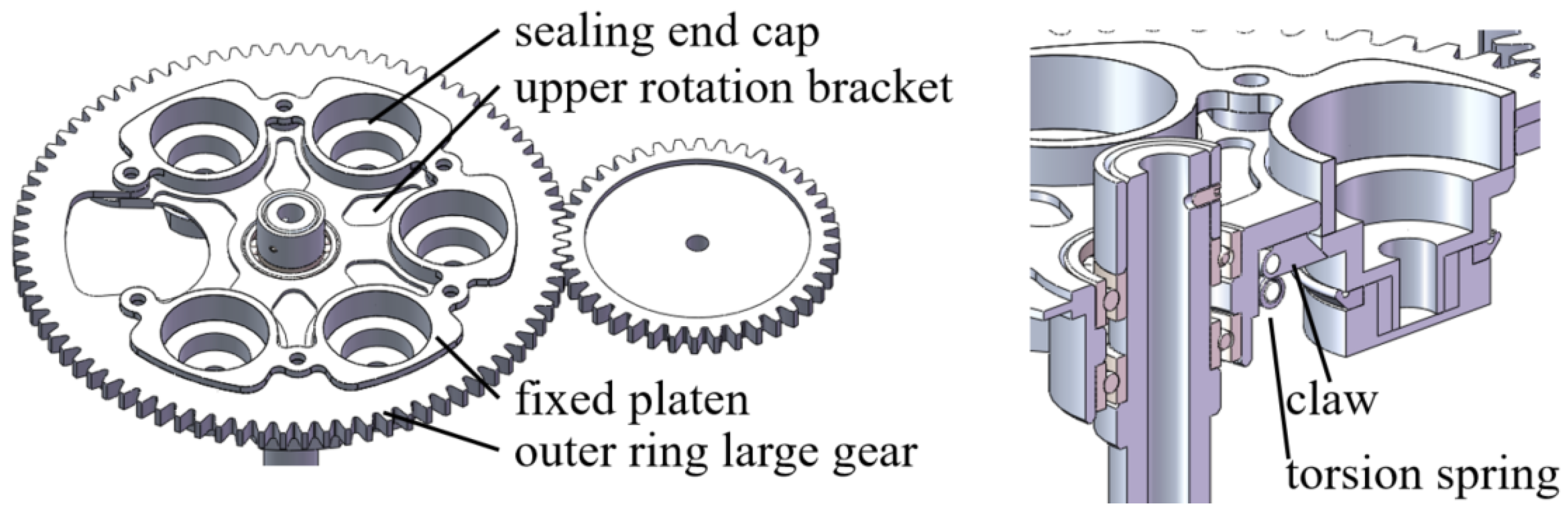
2.3.2. Rotating Mechanism of End Caps
2.3.3. External Bracket
3. Seal Design
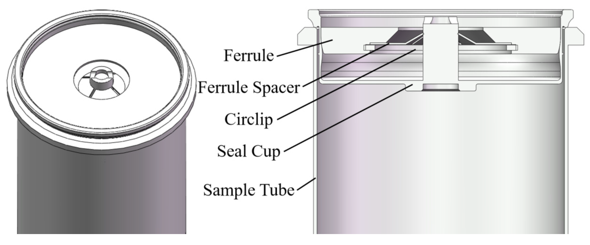
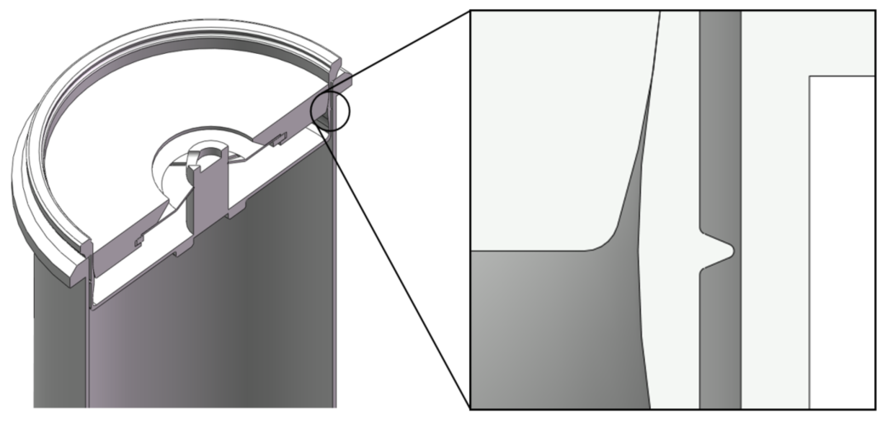
3.1. Lateral Non-Sliding Seal
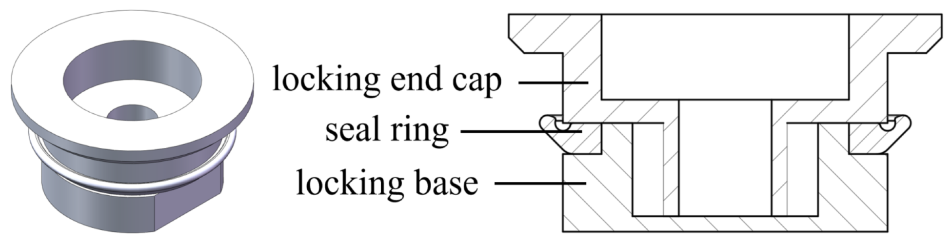
3.2. Lateral Sliding Seal
4. Finite Element Analysis of Sealing Performance
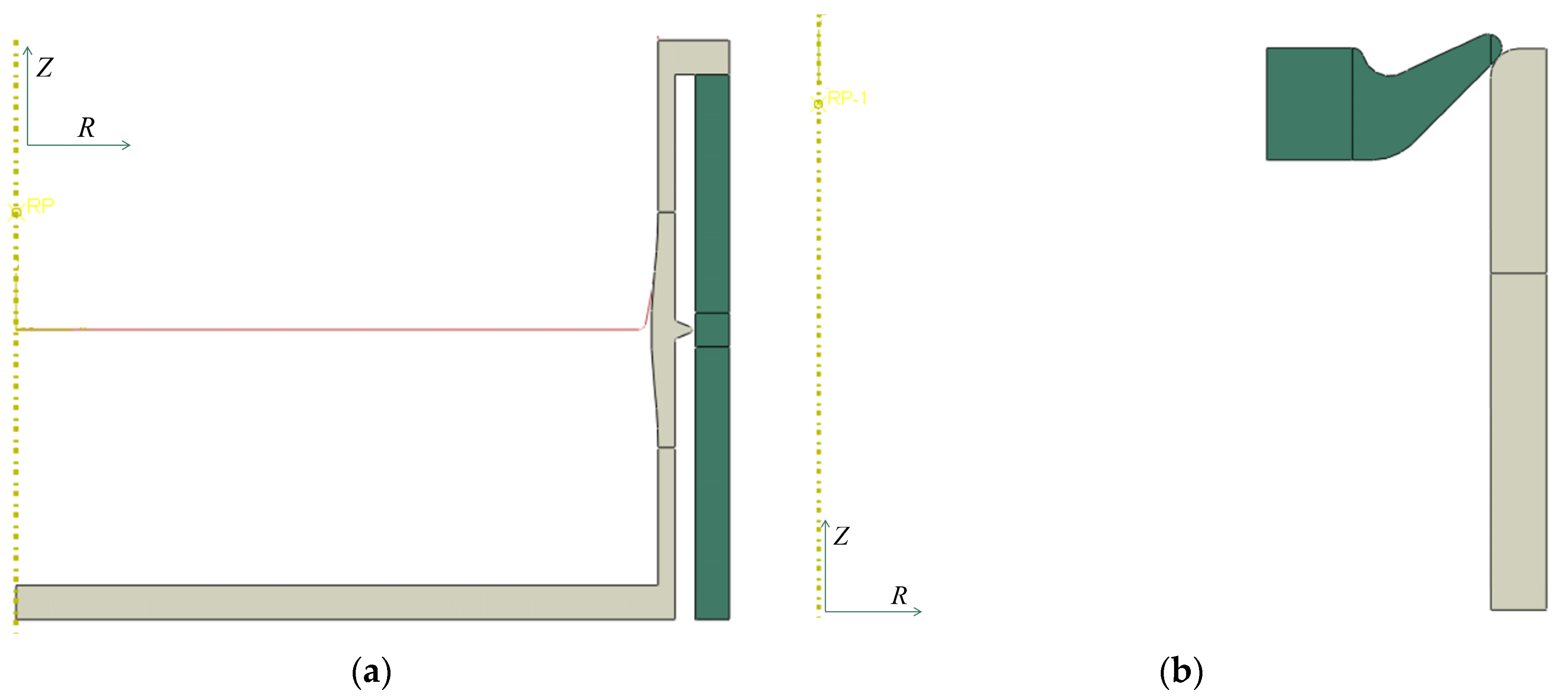
4.1. FEA Model
4.1.1. Lateral Non-sliding Seal
4.1.2. Lateral Sliding Seal
4.2. Material Properties’ Parameters
4.2.1. Lateral Non-Sliding Seal
4.2.2. Lateral Sliding Seal
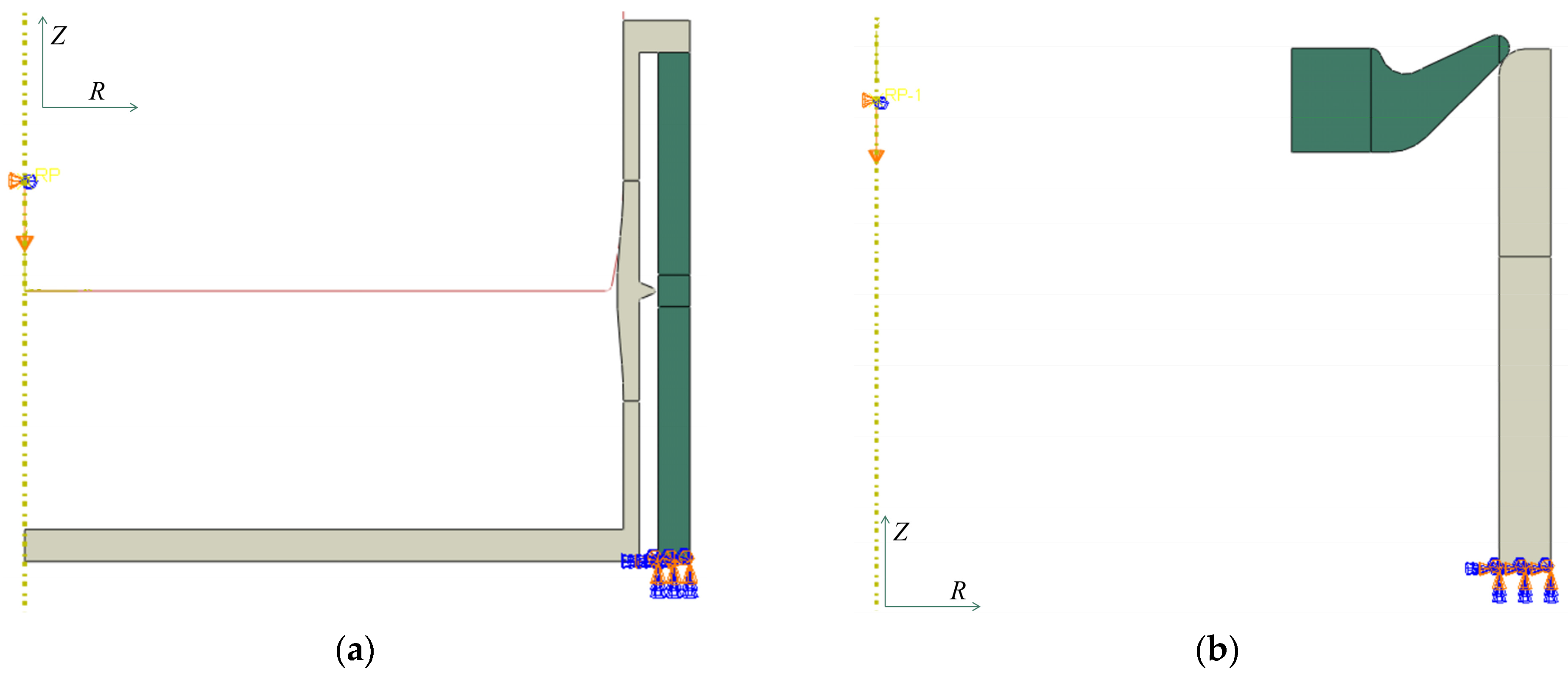
4.3. Boundary Conditions, Connections, and Load
4.3.1. Lateral Non-Sliding Seal
4.3.2. Lateral Sliding Seal
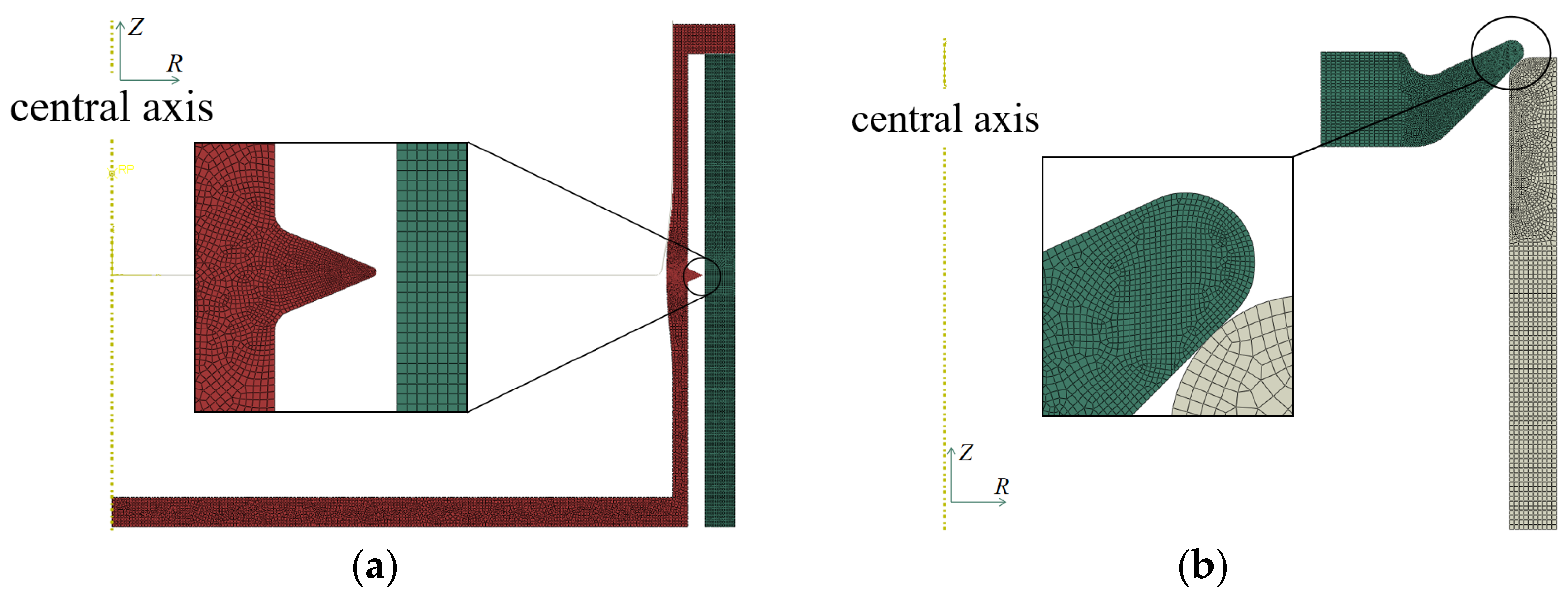
4.4. Meshing
4.4.1. Lateral Non-Sliding Seal
4.4.2. Lateral Sliding Seal
4.5. FEA Results
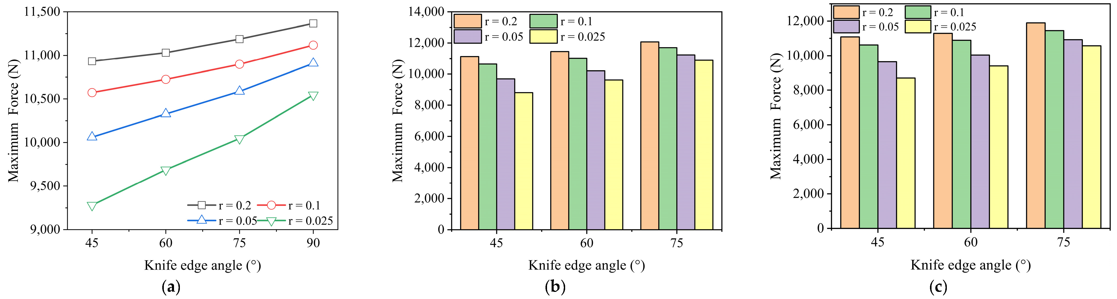
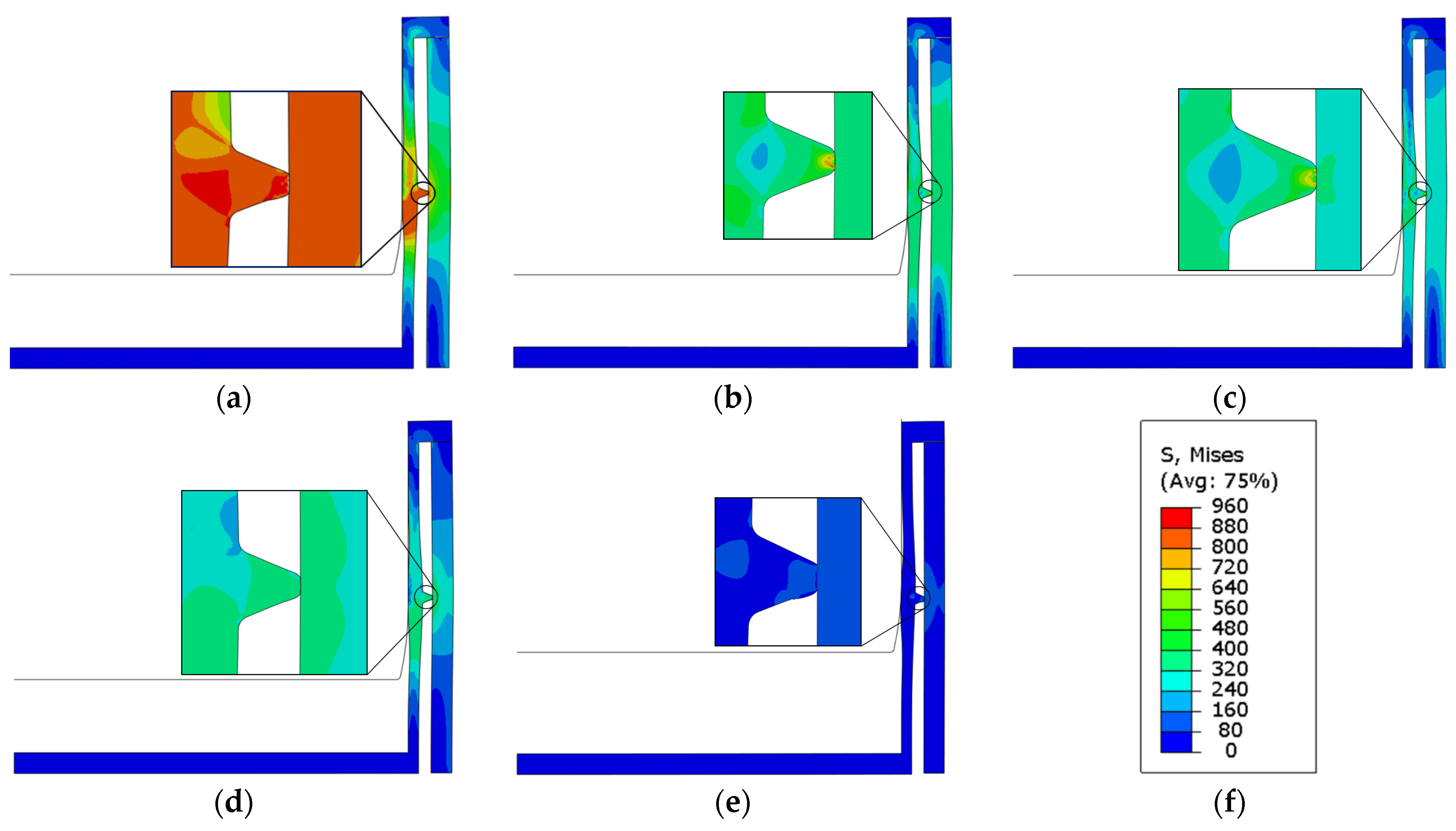
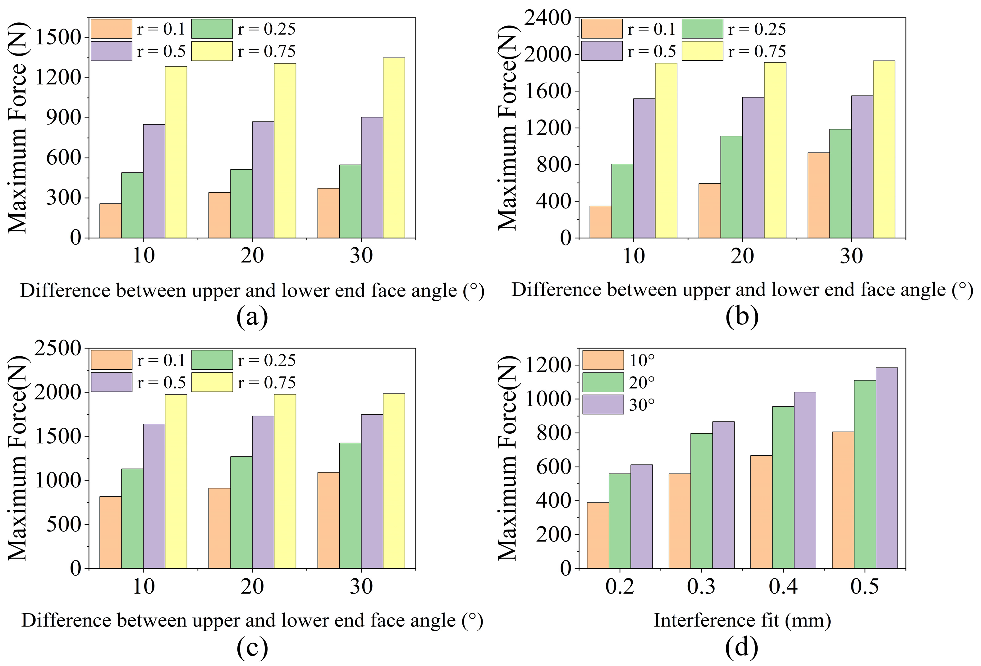
4.5.1. Lateral Non-Sliding Seal
4.5.2. Lateral Non-Sliding Seal in Other Materials
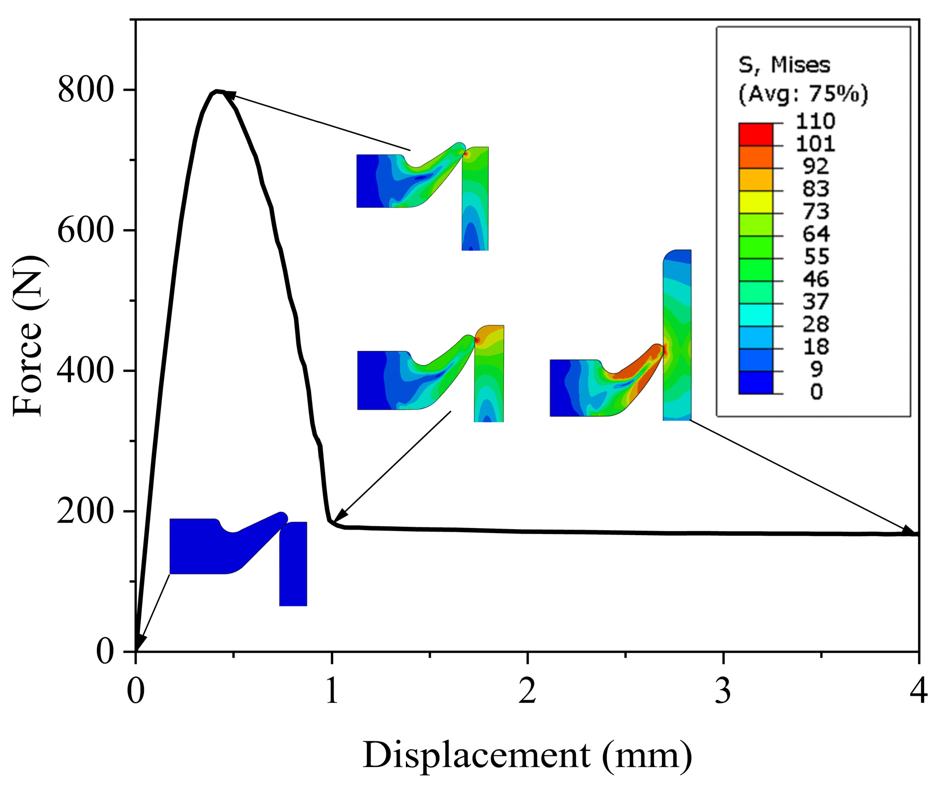
4.5.3. Lateral Sliding Seal
5. Experiment
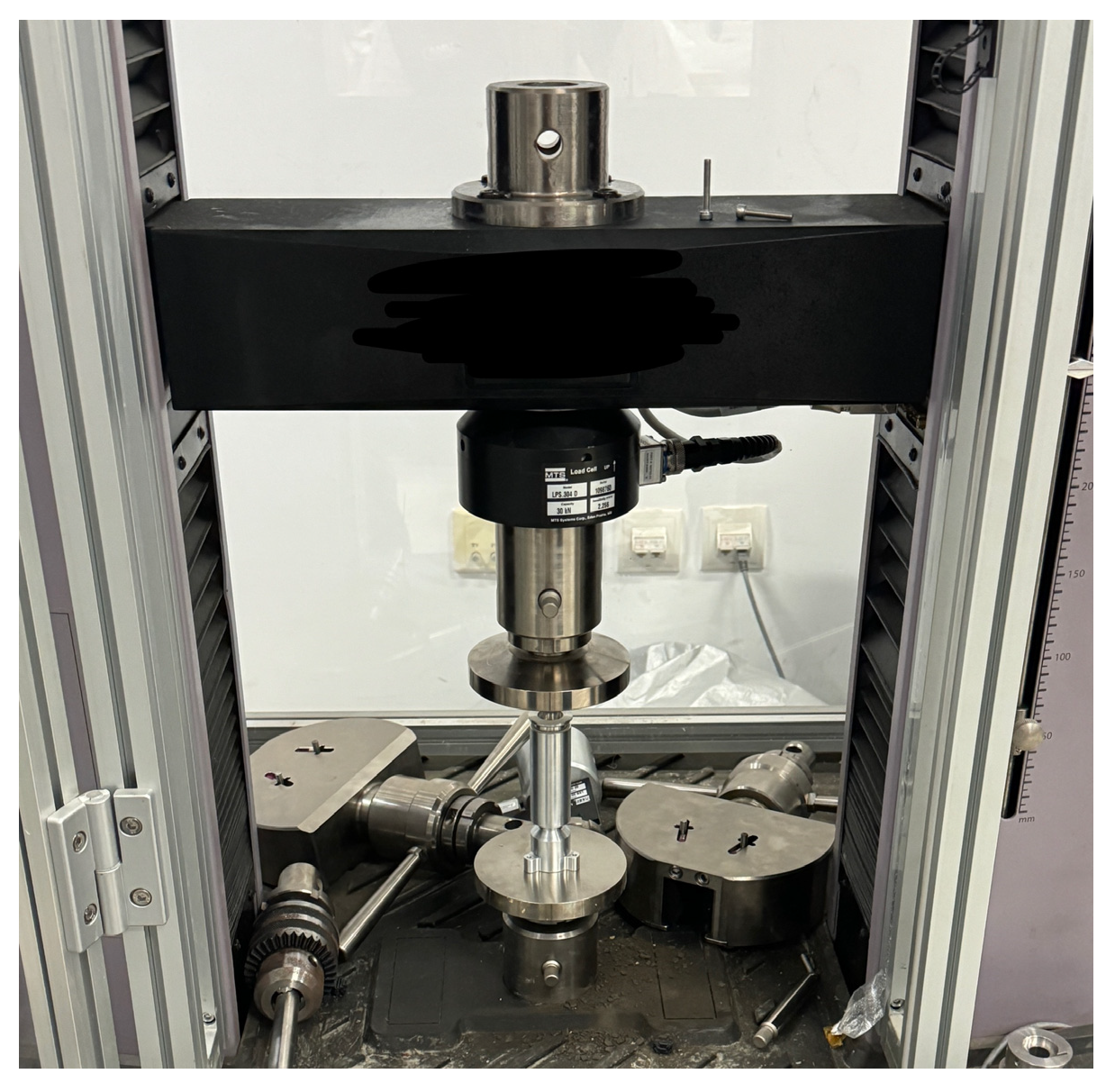
5.1. Actuation Force Testing
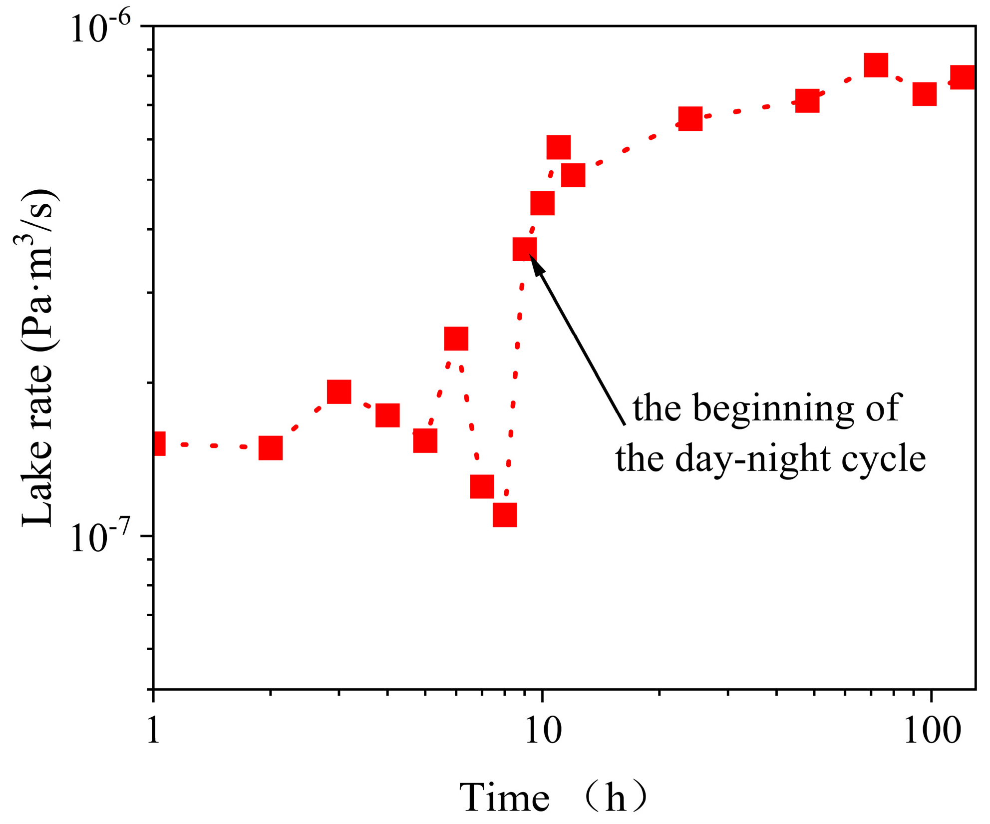
5.2. Leaking Rate Testing
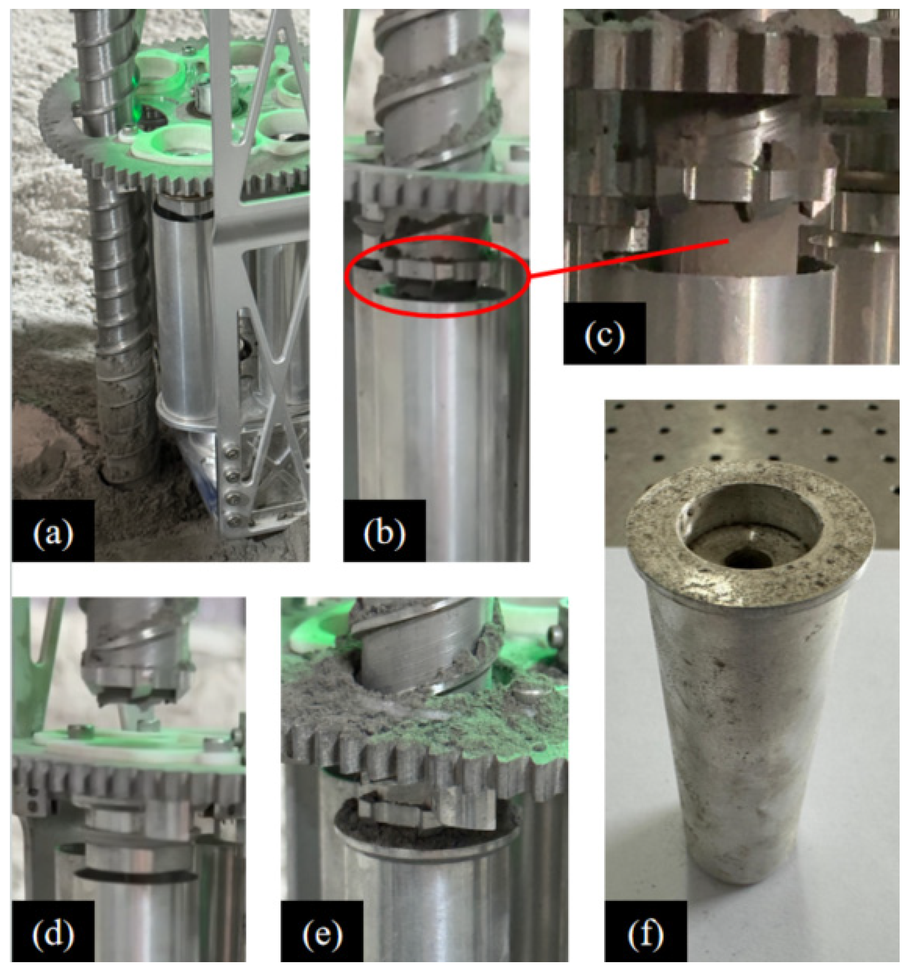
5.3. Working Principle of Autonomous Sample-Collecting System
6. Future Study
7. Conclusions
Author Contributions
Funding
Data Availability Statement
Conflicts of Interest
References
- Kemurdzhian, A.; Gromov, V.; Cherkasov, I.; Shvarev, V. Automatic stations for investigation of the lunar surface. In Automatic Stations for Investigation of the Lunar Surface; Mashinostroenie: Moscow, Russia, 1976; pp. 23–25. [Google Scholar]
- Marov, M.Y.; Huntress, W. Soviet Robots in the Solar System. In Mission Technologies and Discoveries; Springer-Praxis: Chichester, UK, 2011; pp. 219–226. [Google Scholar]
- Shi, X.; Deng, Z.; Quan, Q.; Tang, D.; Hou, X.; Jiang, S. Development of a drilling and coring test-bed for lunar subsurface exploration and preliminary experiments. Chin. J. Mech. Eng. 2014, 27, 673–682. [Google Scholar] [CrossRef]
- Vinogradov, A. Preliminary data on lunar soil collected by the Luna 20 unmanned spacecraft. Geochim. Cosmochim. Acta 1973, 37, 721–729. [Google Scholar] [CrossRef]
- Robinson, M.; Plescia, J.; Jolliff, B.; Lawrence, S. Soviet lunar sample return missions: Landing site identification and geologic context. Planet. Space Sci. 2012, 69, 76–88. [Google Scholar] [CrossRef]
- Yada, T.; Fujimura, A.; Abe, M.; Nakamura, T.; Noguchi, T.; Okazaki, R.; Nagao, K.; Ishibashi, Y.; Shirai, K.; Zolensky, M.E. Hayabusa-returned sample curation in the Planetary Material Sample Curation Facility of JAXA. Meteorit. Planet. Sci. 2014, 49, 135–153. [Google Scholar] [CrossRef]
- Dirri, F.; Longobardo, A.; Palomba, E.; Hutzler, A.; Ferrière, L. Basic design of sample container for transport of extraterrestrial samples. In Proceedings of the European Planetary Science Congress, Riga, Latvia, 17–22 September 2017; p. EPSC2017-2811. [Google Scholar]
- Allton, J.; Bagby, J., Jr.; Stabekis, P. Lessons learned during Apollo lunar sample quanrantine and sample curation. Adv. Space Res. 1998, 22, 373–382. [Google Scholar] [CrossRef]
- Allton, J.H. Catalog of Apollo Lunar Surface Geological Sampling Tools and Containers; Lyndon, B., Ed.; Johnson Space Center: Houston, TX, USA, 1989; pp. 48–62. [Google Scholar]
- Okazaki, R.; Sawada, H.; Yamanouchi, S.; Tachibana, S.; Miura, Y.N.; Sakamoto, K.; Takano, Y.; Abe, M.; Itoh, S.; Yamada, K. Hayabusa2 sample catcher and container: Metal-seal system for vacuum encapsulation of returned samples with volatiles and organic compounds recovered from C-type asteroid Ryugu. Space Sci. Rev. 2017, 208, 107–124. [Google Scholar] [CrossRef]
- Sawada, H.; Okazaki, R.; Tachibana, S.; Sakamoto, K.; Takano, Y.; Okamoto, C.; Yano, H.; Miura, Y.; Abe, M.; Hasegawa, S. Hayabusa2 sampler: Collection of asteroidal surface material. Space Sci. Rev. 2017, 208, 81–106. [Google Scholar] [CrossRef]
- Ji, M.; Sun, L.; Yang, M. Seal Design and Test Verification of Lunar Sample Container. IOP Conf. Ser. Mater. Sci. Eng. 2018, 439, 042025. [Google Scholar] [CrossRef]
- Zhang, B.; Yu, M.; Yang, H. Leakage analysis and ground tests of the O-type rubber ring seal applied in lunar sample return devices. Proc. Inst. Mech. Eng. Part G J. Aerosp. Eng. 2015, 229, 479–491. [Google Scholar] [CrossRef]
- Zhang, B.; Hong, H.; Yu, M.; Yang, H. Leakage analysis and ground tests of knife edge indium seal to lunar sample return devices. Proc. Inst. Mech. Eng. Part G J. Aerosp. Eng. 2019, 233, 2010–2022. [Google Scholar] [CrossRef]
- Bar-Cohen, Y.; Badescu, M.; Bao, X.; Lee, H.J.; Sherrit, S.; Freeman, D.; Campos, S. Synchronous separation, seaming, sealing and sterilization (S4) using brazing for sample containerization and planetary protection. In Proceedings of the Sensors and Smart Structures Technologies for Civil, Mechanical, and Aerospace Systems 2017, Portland, OR, USA, 25–29 March 2017; pp. 47–53. [Google Scholar]
- Gershman, R.; Bar-Cohen, Y.; Hendry, M.; Stricker, M.; Dobrynin, D.; Morrese, A. Break-the-chain technology for potential Mars sample return. In Proceedings of the 2018 IEEE Aerospace Conference, Big Sky, MT, USA, 3–10 March 2018; pp. 1–21. [Google Scholar]
- Younse, P.; de Alwis, T.; Backes, P.; Trebi-Ollennu, A. Sample sealing approaches for Mars Sample Return caching. In Proceedings of the 2012 IEEE Aerospace Conference, Big Sky, MT, USA, 3–10 March 2012; pp. 1–11. [Google Scholar]
- Younse, P.; Aveline, D.; Bao, X.; Berisford, D.; Bhandari, P.; Budney, C.; Chen, F.; Cooper, M.; Chung, S.; Lewis, D. Sample Tube Sealing for Future Proposed Mars Sample Return Missions. In Proceedings of the Lunar and Planetary Science Conference (LPSC 2013), The Woodlands, TX, USA, 18–22 March 2013. [Google Scholar]
- Bao, X.; Badescu, M.; Sherrit, S.; Bar-Cohen, Y.; Campos, S. Heating and thermal control of brazing technique to break contamination path for potential Mars sample return. In Proceedings of the Sensors and Smart Structures Technologies for Civil, Mechanical, and Aerospace Systems 2017, Portland, OR, USA, 25–29 March 2017; pp. 173–180. [Google Scholar]
- Backes, P.; Onstott, T.; Bar-Cohen, Y.; Badescu, M.; Pratt, L.; Helmick, D.; Sherrit, S.; Johnson, A.; Bao, X. Planetary sample sealing for caching. In Proceedings of the 2009 IEEE Aerospace Conference, Big Sky, MT, USA, 7–14 March 2009; pp. 1–10. [Google Scholar]
- Wang, J.; Li, D.; Liu, K.; Wang, Z.; Qing, G.; Wang, Y.; Yan, C.; He, C.; Zhang, R. Numerical and experimental investigation of an automatic brazing vacuum seal system for Mars soil sample return. Vacuum 2024, 219, 112687. [Google Scholar] [CrossRef]
- Bement, L.; Sanok, J. Explosive Joining for the Mars Sample Return Mission. In Proceedings of the 36th AIAA/ASME/SAE/ASEE Joint Propulsion Conference and Exhibit, Las Vegas, NV, USA, 24–28 July 1998; p. 3406. [Google Scholar]
- Wang, J.; Li, X.; Yan, H.; Wang, X.; Wang, Y. Research on titanium-copper explosive welding interface with different welding parameters. Int. J. Adv. Manuf. Technol. 2022, 122, 3595–3606. [Google Scholar] [CrossRef]
- Zhang, B.; Yu, M.; Yang, H.; Hong, H. Research on sealing structure and ground test of lunar sample return devices. In Proceedings of the ASME International Mechanical Engineering Congress and Exposition, San Diego, CA, USA, 15–21 November 2013; p. V001T001A029. [Google Scholar]
- Zacny, K.; Craft, J.; Yachbes, I.; Mumm, E.; Ji, J.; Gorevan, S. Honeybee Robotics approach to technology development and infusion. In Proceedings of the 2010 IEEE Aerospace Conference, Big Sky, MT, USA, 6–13 March 2010; pp. 1–7. [Google Scholar]
- Bao, X.; Younse, P.; Bhandari, P. FE simulation of SMA seal for Mars sample return. In Proceedings of the Sensors and Smart Structures Technologies for Civil, Mechanical, and Aerospace Systems 2013, San Diego, CA, USA, 10–14 March 2013; pp. 1228–1236. [Google Scholar]
- Bao, X.; Younse, P. Finite element analysis of seal mechanism using SMA for Mars sample return. In Proceedings of the Sensors and Smart Structures Technologies for Civil, Mechanical, and Aerospace Systems 2014, San Diego, CA, USA, 9–13 March 2014; pp. 966–974. [Google Scholar]
- Wang, J.; Li, D.; Zhang, R.; Wang, Y.; Qing, G.; Liu, K.; Xie, Y.; He, C. Experimental and analytical studies on behavior of shape memory alloy-based knife-edge seal system for extraterrestrial soil sample return mission. Vacuum 2024, 222, 113048. [Google Scholar] [CrossRef]
- Redmond, L.; Kriechbaum, K.; Younse, P.; Kulczycki, E. Design of Robust Sealing Mechanism for Mars 2020 Sample Tubes. J. Spacecr. Rocket. 2020, 57, 964–974. [Google Scholar] [CrossRef]
- Osterhout, J.T.; Farley, K.A.; Wadhwa, M.; Treffkorn, J.; Kulczycki, E. Helium Leak Rate Measurements of Flight-like Mars 2020 Sample Tubes. Astrobiology 2024, 24, 36–43. [Google Scholar] [CrossRef] [PubMed]
- Moeller, R.C.; Jandura, L.; Rosette, K.; Robinson, M.; Samuels, J.; Silverman, M.; Brown, K.; Duffy, E.; Yazzie, A.; Jens, E. The Sampling and Caching Subsystem (SCS) for the scientific exploration of Jezero crater by the Mars 2020 Perseverance rover. Space Sci. Rev. 2021, 217, 5. [Google Scholar] [CrossRef]
- Yang, J.; Li, X.; Tian, Z.; Wang, Z.; Han, R.; Yuan, Z.; Mu, R.; Zhao, H. Design of a Lunar Regolith Sampling System for Large-Scale Rover Traversals. In Proceedings of the 2023 IEEE International Conference on Real-time Computing and Robotics (RCAR), Datong, China, 17–20 July 2023; pp. 87–92. [Google Scholar]
- Lind, J.; Lindholm, P.; Qin, J.; Rudolphi, Å.K. Friction and wear studies of some PEEK materials. Tribol. Finn. J. Tribol. 2015, 33, 20–28. [Google Scholar]


| Names | Symbols | Values |
|---|---|---|
| Knife-edge angle | θ | 45/60/75 |
| Knife-edge radius | r | 0.025/0.05/0.1/0.2 |
| Interference fit | t | 0.2/0.3/0.4 |
| Different shapes of the knife edge | / | Symmetrical/non-symmetrical I/non-symmetrical II |
| Names | Symbols | Values |
|---|---|---|
| Angle of the bottom face | θ1 | 30/45/60 |
| Angle of the top face | θ2 | θ1 − 10/θ1 − 20/θ1 − 30 |
| Interference fit | t | 0.2/0.3/0.4/0.5 |
| Tip radius | r | 0.1/0.25/0.5/0.75 |
| Materials | Yield Strength/MPa | Modulus of Elasticity/MPa | Poisson’s Ratio |
|---|---|---|---|
| Titanium alloy TC4 | 830 | 114,000 | 0.33 |
| Stainless steel 304L | 317 | 227,156 | 0.33 |
| Stainless steel 316L | 205 | 197,328 | 0.33 |
| Aluminum alloy 6061Al | 55 | 75,857 | 0.33 |
| PEEK 450G | 97 | 3500 | 0.4 |
| Number | Inner Diameter of the Sample Tube | Seal Ring Outer Diameter |
|---|---|---|
| 1 | 24.11 mm | 24.40 mm |
| 2 | 24.13 mm | 24.40 mm |
| 3 | 24.11 mm | 24.38 mm |
| Model | Values |
|---|---|
| Working voltage U/V | 24 |
| Maximum speed ωmax/rpm | 3000 |
| Holding torque T/N·m | 0.4 |
| Step angle θ/° | 1.8 |
Disclaimer/Publisher’s Note: The statements, opinions and data contained in all publications are solely those of the individual author(s) and contributor(s) and not of MDPI and/or the editor(s). MDPI and/or the editor(s) disclaim responsibility for any injury to people or property resulting from any ideas, methods, instructions or products referred to in the content. |
© 2024 by the authors. Licensee MDPI, Basel, Switzerland. This article is an open access article distributed under the terms and conditions of the Creative Commons Attribution (CC BY) license (https://creativecommons.org/licenses/by/4.0/).
Share and Cite
Mu, Y.; Yuan, Z.; Mu, R.; Zhao, H.; Ning, Z.; Li, X.; Gan, T.; Du, T.; Wang, Z.; Han, R.; et al. Design of an Automatic Sealing Mechanism for Extraterrestrial Sample-Collecting Robot. Aerospace 2024, 11, 517. https://doi.org/10.3390/aerospace11070517
Mu Y, Yuan Z, Mu R, Zhao H, Ning Z, Li X, Gan T, Du T, Wang Z, Han R, et al. Design of an Automatic Sealing Mechanism for Extraterrestrial Sample-Collecting Robot. Aerospace. 2024; 11(7):517. https://doi.org/10.3390/aerospace11070517
Chicago/Turabian StyleMu, Yujian, Zihao Yuan, Ruinan Mu, Haifeng Zhao, Zhitao Ning, Xihan Li, Tianyue Gan, Tao Du, Zhiqiang Wang, Rujin Han, and et al. 2024. "Design of an Automatic Sealing Mechanism for Extraterrestrial Sample-Collecting Robot" Aerospace 11, no. 7: 517. https://doi.org/10.3390/aerospace11070517
APA StyleMu, Y., Yuan, Z., Mu, R., Zhao, H., Ning, Z., Li, X., Gan, T., Du, T., Wang, Z., Han, R., & Shen, Z. (2024). Design of an Automatic Sealing Mechanism for Extraterrestrial Sample-Collecting Robot. Aerospace, 11(7), 517. https://doi.org/10.3390/aerospace11070517