Article

Lean Demonstration of On-Board Thermal Anomaly Detection Using Machine Learning

1
Interdisciplinary Centre for Security, Reliability and Trust, University of Luxembourg, 4365 Esch-sur-Alzette, Luxembourg
2
NXP Semiconductors, 06560 Valbonne, France
3
Melbourne Space Lab, University of Melbourne, Melbourne, VIC 3010, Australia
*
Author to whom correspondence should be addressed.
Aerospace 2024, 11(7), 523; https://doi.org/10.3390/aerospace11070523
Submission received: 23 February 2024 / Revised: 2 June 2024 / Accepted: 13 June 2024 / Published: 27 June 2024

Abstract

:
Moore’s law states that the performance of computers doubles about every two years. This has dramatic consequences for any modern high development and for satellites. The long development cycles cause these expensive assets to be obsolete before the start of their operations. The advancement also presents challenges to their design, particularly from a thermal perspective, as more heat is dissipated and circuits are more fragile. These challenges mandate that faster spacecraft development methods are found and thermal management technologies are developed. We elaborate on existing development methodologies and present our own lean method. We explore the development of a thermal anomaly-detection payload, extending from conception to in-orbit commissioning, to stimulate discussions on space hardware development approaches. The payload consists of four miniaturized infrared cameras, heating sources in view of the cameras simulating an anomaly, an on-board processor, and peripherals for electrical and communication interfaces. The paper outlines our methodology and its application, showcasing the success of our efforts with the first-light activation of our cameras in orbit. We show our lean method, featuring reference technical and management models, from which we derive further development tools; such details are normally not available in the scientific-engineering literature. Additionally, we address the shortcomings identified during our development, such as the failure of an on-board component and propose improvements for future developments.

1. Introduction

Space system development methodologies have been an active field of research for many years [1,2,3,4]. However, this research often remains theoretical and of limited applicability if no system has been commissioned for in-space operations. The University of Luxembourg participates in this research through its nanosatellite and sub-nanosatellite development programs.
Implementing commissioned space hardware and software is expensive due to the inherent costs associated with system engineering, management, safety and security, product and quality assurance, operations, procurement of high-quality hardware, and launches. These tasks do not directly lead to scientific publications, which are a key performance indicator for university researchers.
Teaching using actual space missions is also costly due to the difficulties in synchronizing projects with the academic calendar, managing student turnover, ensuring knowledge continuity, and addressing the diverse backgrounds of students. These challenges discourage research at high technology readiness levels.
Despite these obstacles, there is a need for research into new methodologies. As computers continue to develop rapidly following Moore’s law, current methods often lead to delays and cost overruns [5]. Furthermore, industry demands graduates with practical knowledge beyond theoretical understanding.
The research and development of smaller scale hardware can address these needs and challenges. For instance, payloads integrated into a satellite can utilize satellite resources, reducing overall complexity. The shorter development duration of these projects allows for testing new approaches and involving students [6,7,8,9].
In this context, we have developed a subsystem for operation in orbit, enabling us to experiment with new technologies and development approaches. Our research focuses on developing a system that monitors the thermal conditions inside a spacecraft and uses artificial intelligence algorithms to analyze the data, specifically aiming to detect thermal anomalies.

1.1. Skykraft’s Hosted Payload Programme

Skykraft Ltd., based in Canberra, Australia, designs, builds, and operates satellites to acquire Automatic Dependent Surveillance-Broadcast (ADS-B) data transmitted by airplanes. These data contain critical air traffic information and is commercially provided to customers such as airlines. They launched a stack of five Block II satellites on 3 January 2023, and a second block of similarly designed Block III satellites on 12 June 2023.
Skykraft offers universities to host a payload consisting of a standardized printed circuit board called Skykard under their Skyride program, featuring:
  • Low-cost hosting.
  • Well defined interfaces described in an interface control document [10].
  • Provision of interface test software and test jig.
  • Expert advice.
The University of Luxembourg gladly made use of the payload hosting opportunity on Block III.

1.2. The uni.lu/SnT AI4Space Skykard

The Skykraft launch opportunity enables us to carry out our applied system-engineering research and develop an experimental payload called AI4Space. It consists of a printed circuit board (PCB) and features four miniaturized infrared cameras observing the PCB and components placed on it. To simulate thermal anomalies, we integrated four resistive heaters in the field of view of the cameras. Each 20 Ohm resistor produced 0.5 W of heat when enabled. We verified this to be enough to allow its detection and not to exceed the allocated allowed power consumption of our payload.
The cameras will be operated by a Raspberry Pi microcomputer, which also relays the imagery, runs a machine-learning algorithm, as well as processes the images.
The objectives of our AI4Space in-flight payload development and research are:
  • Develop and test a payload development approach.
  • Demonstrate an on-board anomaly-detection algorithm using machine learning.
  • Develop a proof-of-concept for a versatile thermal anomaly-detection system.

1.2.1. Anomaly Detection

The ever-increasing performance of satellites, thanks to advances in satellite technology and demand in performance and ongoing miniaturization, eventually poses challenges to satellites, for instance, due to volumetric heat dissipation [11].
In addition, often, terrestrial technology, such as microprocessors, is used to this end [12,13]. However, it is not designed for a vacuum-thermal environment. Furthermore, these commercial off-the-shelf (COTS) components are more susceptible to radiation events, which can lead to a degradation in their performance, characterized by increased power consumption and, consequently, greater thermal dissipation [14].
This suggests the need to control and monitor the thermal situation of modern satellite on-board processors during operations. New miniaturized sensors, together with new detection methods, can improve anomaly detection [15,16]. In particular, the advent of artificial intelligence enables the unprecedented processing of complex data. Those new technologies can improve thermal monitoring of satellite electronics [17].
We aim to show how to reliably address the thermal challenges with the newly available technology.
Thermal anomalies can be categorized as follows:
  • Out-of-range anomalies: an anomalous behavior causes high heating. The excessive temperature endangers the hardware. A measured temperature value exceeds a defined permissible maximum value. Such a situation is often addressed using embedded sensors and simple comparative analysis.
  • Within-range anomalies: An anomalous behavior causes a minor heating, thus a minor increase in temperature. The measured values remain within range. The pattern of temperature measurement is, however, anomalous [18]. Such complex anomalies can only be detected by high-fidelity algorithms or human intervention. Detecting those helps the understanding of emerging satellite health issues and can thus serve predictive maintenance [19] applications.
Within this AI4Space project, we chose to address the former. We will target the latter in a future research project.
In particular, we intend to detect a localized overheating situation. Those could be representative of, for example, a poor soldering spot or degraded microprocessor chip. To this end, we produce hotspots on our base-PCB simulating anomalous overheating. This will be our true positive situation. We also stress our on-board microprocessor through a computational task producing a nominal yet significant heating, which will be a false positive situation.
A sufficient algorithm can distinguish the anomalous from the nominal thermal situation, thus detecting a maximum number of true positives and a minimum number of false positives. Moreover, it should be robust with respect to the detection situation, i.e., the environment the observation target is placed and receives heat from.

1.2.2. Why Artificial Intelligence?

The outlined anomaly-detection approach provides us with a simple use case and the opportunity to verify the feasibility of deploying a machine-learning algorithm on board using a microcomputer. Our anomaly-detection task performs a simple classification of images and provides an output of whether a given image is anomalous or nominal. Image classification is one of the domains of machine learning where a network learns to assign a class label to an input image. Specifically, this is a binary classification problem, and different machine-learning approaches can be applied to solve such problems, including support vector machines [20], naive Bayes classifier [21], logistic regression [22], and neural networks [23].
The two important constituents of machine learning are algorithms and datasets. The training and validation data are often obtained through experiments conducted in controlled environments. However, acquiring such images on the ground, replicating similar image characteristics encountered in space environments precisely, poses a significant challenge. The data can come from one of the sources: synthetic (generated from simulation), data acquired at room temperature, or data acquired in vacuum chambers. While data acquired in vacuum chambers more closely represent space-like conditions, it still diverges due to variations in satellite orbital dynamics, attitude parameters, and the positioning of the target computing board within the satellite.
The supervised learning approach for thermal anomaly detection necessitates a curated dataset containing labelled images depicting both normal and anomalous conditions. The dataset used for training and validation was gathered from controlled experiments conducted on the engineering model within a vacuum chamber.
We aim to mitigate the data deficit by extending the potential of algorithms to perform anomaly detection. Leveraging the inherent characteristics of neural networks facilitates the exploration of hierarchical, distributed representations that align with the underlying causative factors within the observed data. Given the non-linear nature and uncertainty between the data-collection environment and the deployment environment, neural networks are more suitable to tackle this problem [24]. We use a deep neural network architecture to solve the problem end-to-end, i.e., image to classification output, and extract hidden relationships to generalize well for the data not specifically seen during training phase.
Though anomaly detection is simply undertaken as a classification task, this development setup will allow us to study the suitability of running AI algorithms in larger satellites in the future. Larger on-board computation will enable accurate pixel-wise prediction and, in turn, pinpoint the location of anomalies in hardware.

1.3. Available Project Development Methodologies

Space project management involves running a project to achieve its goals. It is a subject of discussion and standardization [25,26]. Each project is unique and requires the tailoring of the available methodologies. Additionally, project-management methodologies evolve over time through ongoing research, including our own.
Before starting our project, we brainstormed the underlying principles of space product development and space project management, which we outline in the following subsections. This process helped us choose a methodology suitable for our needs.
In particular, we focused on:
  • Phasing of projects.
  • The extent to which projects are carried out iteratively.
  • How technical models are used to develop the product.
Our methodology and results are detailed in the remainder of the manuscript.

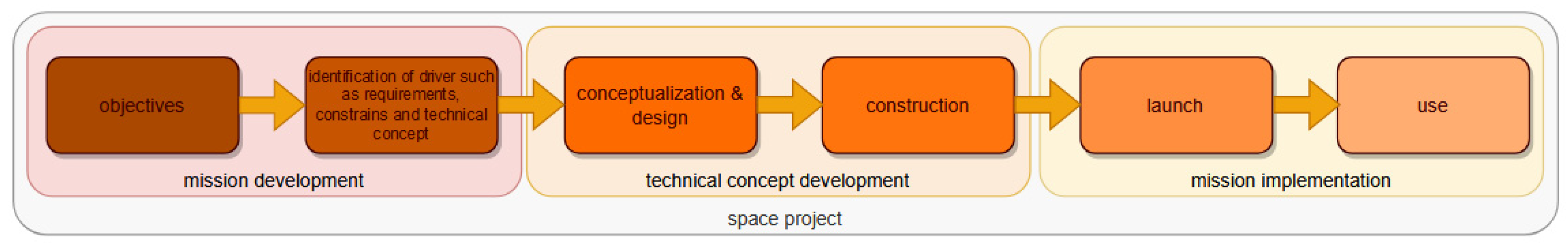
1.3.1. Phases of Space Projects

An important aspect in project management is breaking it down into phases. Deviating from the typical naming conventions, we define three major phases:
  • Mission development.
  • Technical concept development.
  • Mission implementation.
This is illustrated in Figure 1. Within the first phase, work is abstract and defines the mission. Typically, a project plan is produced here. Thereafter, in the technical concept development phase, the work is concrete and follows the project plan. First, the design is finalized; then, the space product is produced. In the third phase, the launch takes place followed by the use, i.e., the operation of the space product. The work carried out in the third phase is very concrete and mostly procedural. The space product is disposed of as last step of the use.
In this manuscript, we focus on the first and second phases of the space project, as they determine the performance, duration, cost, and consequently the success of the overall mission—deserving thorough research. Therefore, we also focus on the first two objectives listed in Section 1.2. Concentrating on the initial two phases is crucial as they commit up to 90% of the project cost (refer to Figure 2; our first two phases range from the indicated inception until the ORR). We also provide a limited report on the third phase, i.e., the in-orbit commissioning, to assess the success of the previous phases.
Exhaustive results of the mission implementation, that is, the operating of our payload, will be presented in a future publication.
Before reporting on our approach and results from Section 5 on, we elaborate on underpinning concepts of the two first phases in the following two subsections.

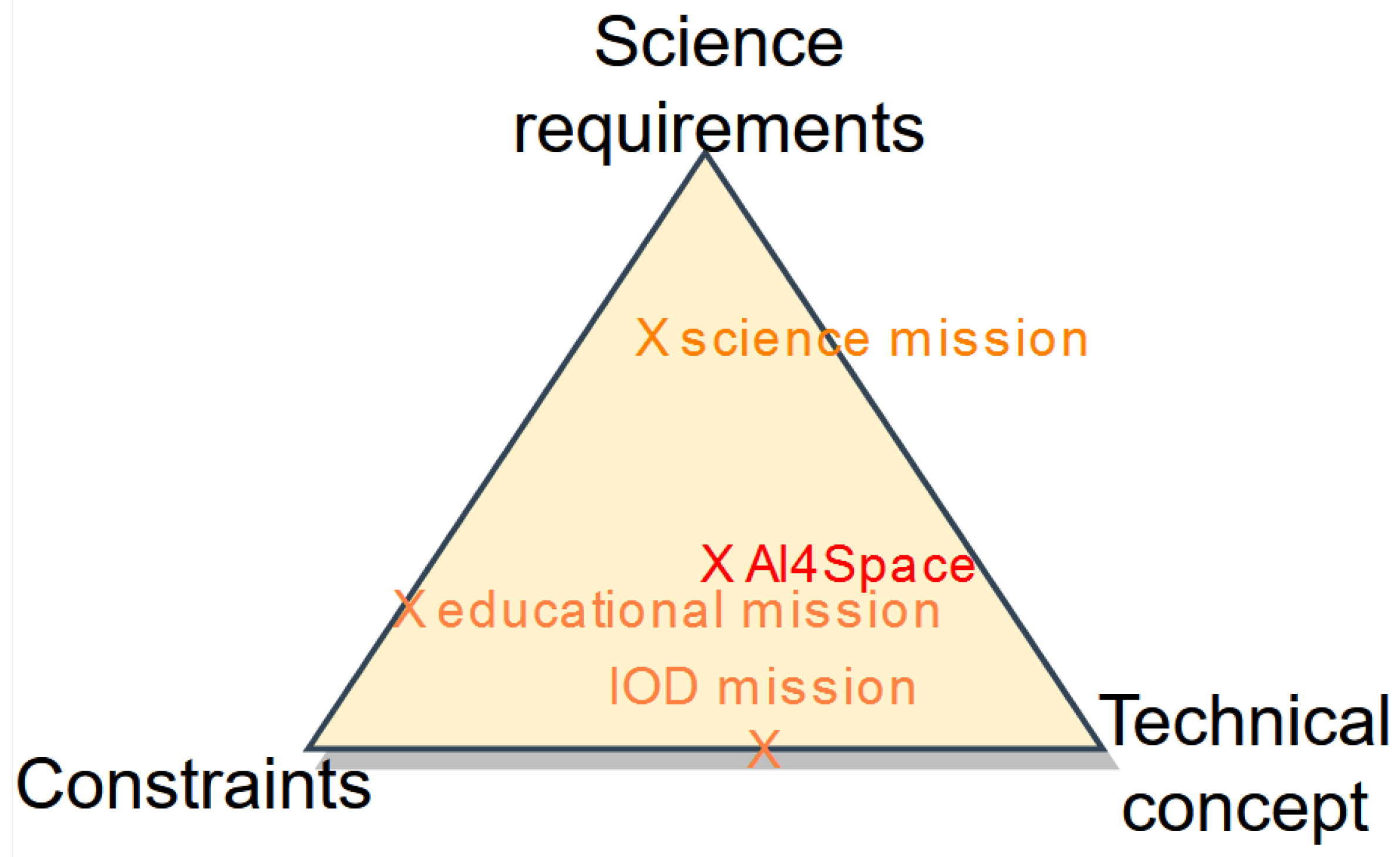
1.3.2. Mission Development

All space mission projects start with an objective for the mission at hand. Those can differ widely from mission to mission and range from purely technical experimentation, such as the demonstration of a new technology, through scientific investigations, such as astronomical observations, to political motives, e.g., to show capabilities.
The objectives give rise to one or a mix of mission drivers of the development. Within our methods, we categorize three types:
  • Scientific requirements. For instance, flagship scientific missions always need the development of beyond-the-state-of-the-art sensors to achieve their groundbreaking objective. The requirement and the consequently needed development govern the mission.
  • Constraints, such as a budget envelope, are formulated for most, if not for all, missions. For some, however, the compliance to constraints is dominating over other aspects [28]. Constraints are often defined by the sponsor of a mission, such as a space agency. Educational missions are often constraint-driven. Those often do not have an inherent scientific objective, but their goal is to train students.
  • Some missions are being dictated a concept, which then takes precedence of other potential drivers. This is in particular the case for CubeSat [29] and satellite bus in-orbit demonstration missions.
Before commencing the development of the technical concept, the driver needs to be identified. In case the technical concept is a priori defined as the driver, the compatibility of science requirements and constraints with the concept needs to be checked.
All three driver categories are present in all space missions, though to a varying extent. This is illustrated in Figure 3 in the driver triangle. This extent defines the mission and its implementation.
After formulation of objectives and the identification of the driver or driver mix, the mission is implemented through conceptualization and design, then construction, then launch and operations.

1.3.3. Technical Concept Development

The second phase, development of technical concept, consists of two distinctive steps:
  • Conceptualization and design.
  • Construction, which can be further subdivided into:
    (a)
    Manufacturing, that is, the assembly of the spacecraft from its parts; and
    (b)
    Verification, that is, the check whether the design requirements are met.
Here, the design is advanced using first simple and then, later, sophisticated design tools to create a concept responding to the objectives. Then, hardware is produced.

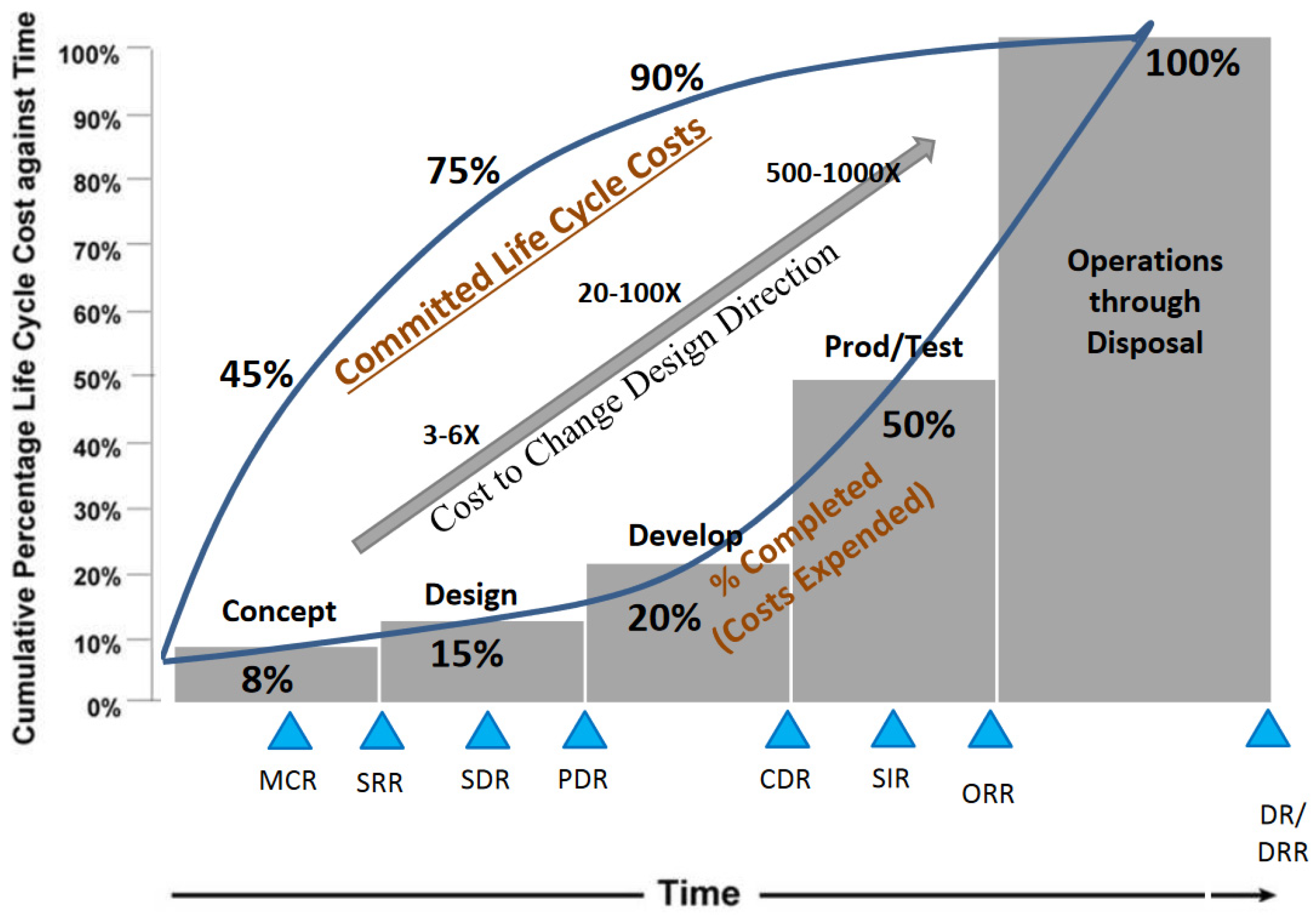
1.3.4. Methods of Space Project Development

Different development methods are used within space projects. They are chosen in the first phase and then used until launch. These include, for instance:
  • Lifecycle management, i.e., the time-wise implementation.
  • Model management, i.e., the use of descriptive models to advance design and construction.
For the first, the lifecycle management aspect, two extreme approaches are typically said to exist:
  • Waterfall, being the successive, prespecified progression from initiation to the end. In each step, a new aspect is addressed leading to the final product.
  • Iterative, following a progression in smaller steps, which are executed sequentially or in parallel. Agile [1,30,31] is a common set of such approaches. In many of those, all development aspects are addressed in each step in order to gradually improve their fidelity.
Space projects typically employ a degree of the waterfall approach, as there is a natural transition from conceptualization and design to the construction phase. A rigorous waterfall approach uses low-cost analytical methods initially before producing hardware in the construction phase. This allows for low-cost changes during the conceptualization and design phase, but it accumulates risks related to hardware work.
In many iterative approaches, the product’s functionality is implemented in hardware early on, which has customer value. This ensures that a functional concept is pursued, mitigating construction risks early. However, once some functionalities are implemented, the overall concept cannot be easily changed, introducing concept risk.
An iterative approach is always present to some extent in space projects, as early designs are continuously updated based on new findings during the design activity.
Space projects typically employ both approaches, waterfall and iterative, to a varying degree. Typically, the design is finished at least within a few cycles at concept level with increasing detailedness. Hardware breadboards of critical elements are sometimes manufactured. Then, a non-reversible step towards the construction is taken at the so-called critical design review (CDR), where the design is frozen and construction begins.
The choice to use either approach defines the development risk profile.
Whether the waterfall or the iterative approach is dominant highly depends on aspects such as:
  • Project drivers;
  • Need or interest in innovation;
  • Background knowledge;
  • Available facilities;
  • Complexity of the project;
  • Accepted exposure to construction or concept risk.
CubeSat missions [32], for instance, borrow from the agile method because the technical concept, the CubeSat formfactor, is known from the beginning and some construction work is typically carried out early-on.
While regarding the different development approaches, attention needs to be paid to the definition of the end product. While the end product often is the functional satellite in orbit, companies such as PlanetLabs’ end product is a constellation. Thus, the development cycles include the development, launch, and operations of satellites.
For the model management approach, two extremes exist among many large model approaches:
  • Model-based approach [33]. A central repository is used to list, maintain, and verify requirements, interfaces, and results of analyses, usually in a formal or semi-formal way. The approach is efficient for very large projects during the mission development and conceptualization phase but is of limited utility for later project phases.
  • Domain-specific models. Here, the development is based on a number of computer and physical models such as a computer-aided-design (CAD) model. This approach is often coupled with the waterfall approach and may be used until operations. Technical domain-specific models can be used to simulate and verify subsystem-specific requirements.

1.4. Outline of the Manuscript

In the previous section, we outlined the context of our methodological research, specifically describing the available space development methodologies. In Section 2, we detail our own methodologies. Section 3 briefly covers the operation of our payload. In Section 4, we present the results of our research, demonstrating the success of the development through a “first light” observation. The manuscript concludes with our findings and an outlook on future research in Section 5 and Section 6, respectively.

2. Our Methodology

2.1. AI4Space Project Analysis

Upon having reviewed project-management and system-engineering methodologies, we analyzed the needs of our AI4Space project and consequently selected methods suitable for us.
We found that AI4Space:
  • defines scientific requirements,
  • was given a rough timeline and interface definition as constraint,
  • was given envelope information on dimensions, power consumption, and material use describing the technical concept.
The AI4Space mission thus falls in the middle of the driver space as indicated in Figure 3.
We were given significant input-defining features of our technical concept. In addition, due to our objectives, further features can be formulated. Our technical concept can thus be described as:
  • having relatively low system-engineering complexity,
  • not employing radiofrequency equipment,
  • not employing mechanisms,
  • not responsible for power generation or storage,
  • needing flight hardware quality.
It is therefore, from a system-engineering point of view, relatively simple, except for the fact that flight hardware is developed requiring a controlled and high-quality approach.

2.2. Our Lean Management Approach and Hybrid Waterfall-Iterative Approach

The overall low system complexity suggests a low-complexity management and development approach is made use of that enables the necessary quality and avoids waste of resources. Consequently, we chose a lifecycle and model approach as outlined in the following sections, which we call the lean space project management and development approach.
For the life-cycle management aspect, the AI4Space project chose to adopt a waterfall approach for the development, except for the software. The waterfall approach aligns well with the domain-specific-models-based approach and the low complexity. The software can mostly be developed independently from the hardware. A rather iterative/agile approach was assumed. Both approaches are described below.

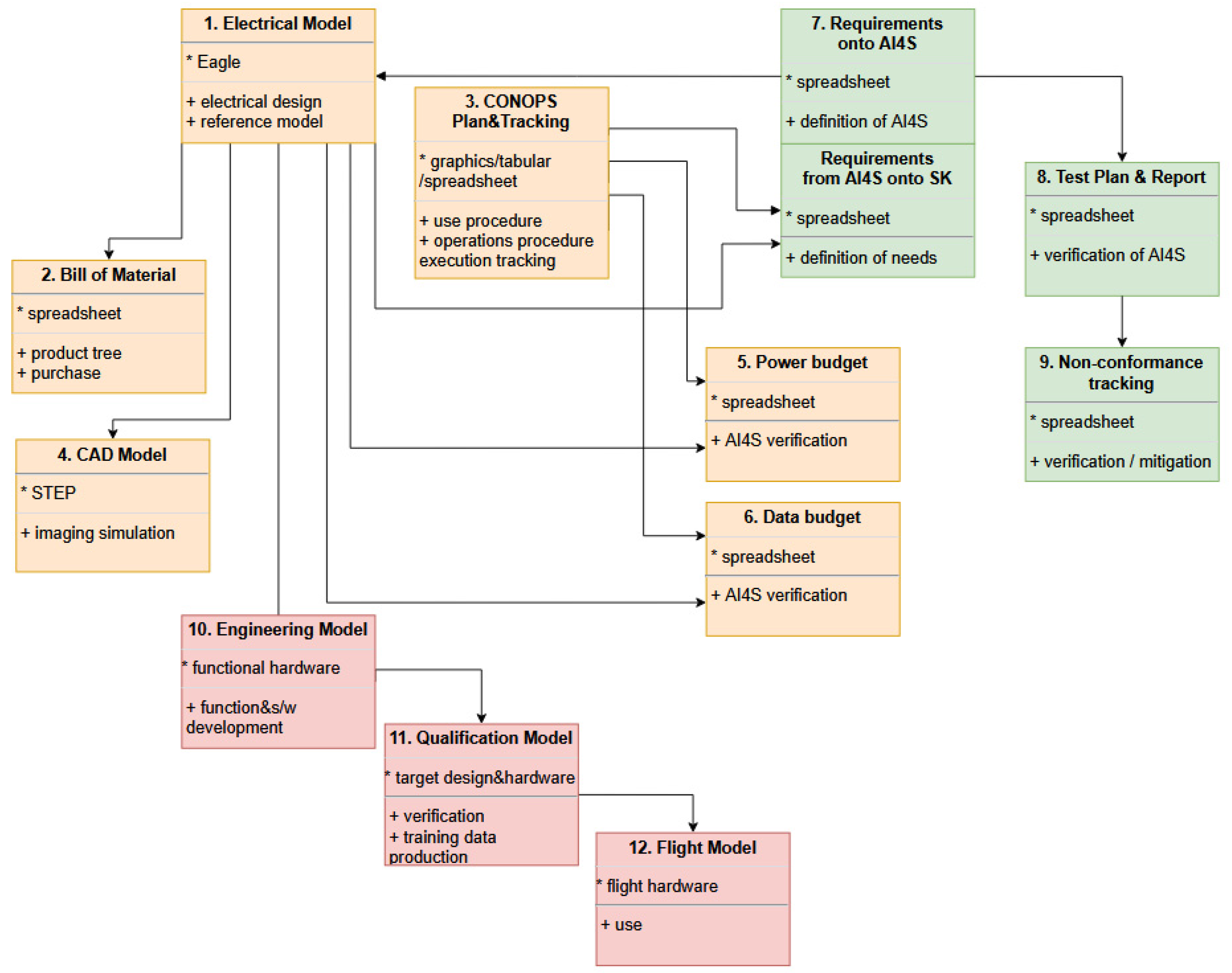
2.3. Our Domain-Specific-Models Approach

The low complexity of our system allows the definition of a reference technical model and derivation of further models from it. We thus mostly used domain-specific models for the model-management aspect and established three groups of models for our models-based approach:
  • Technical models,
  • Management models,
  • Software model.
Care was taken to assure that each model is traceable to a reference model at the top of the tree. In the case of the technical models, it was in our case the electrical model.
The technical models used were the following:
  • Virtual models.
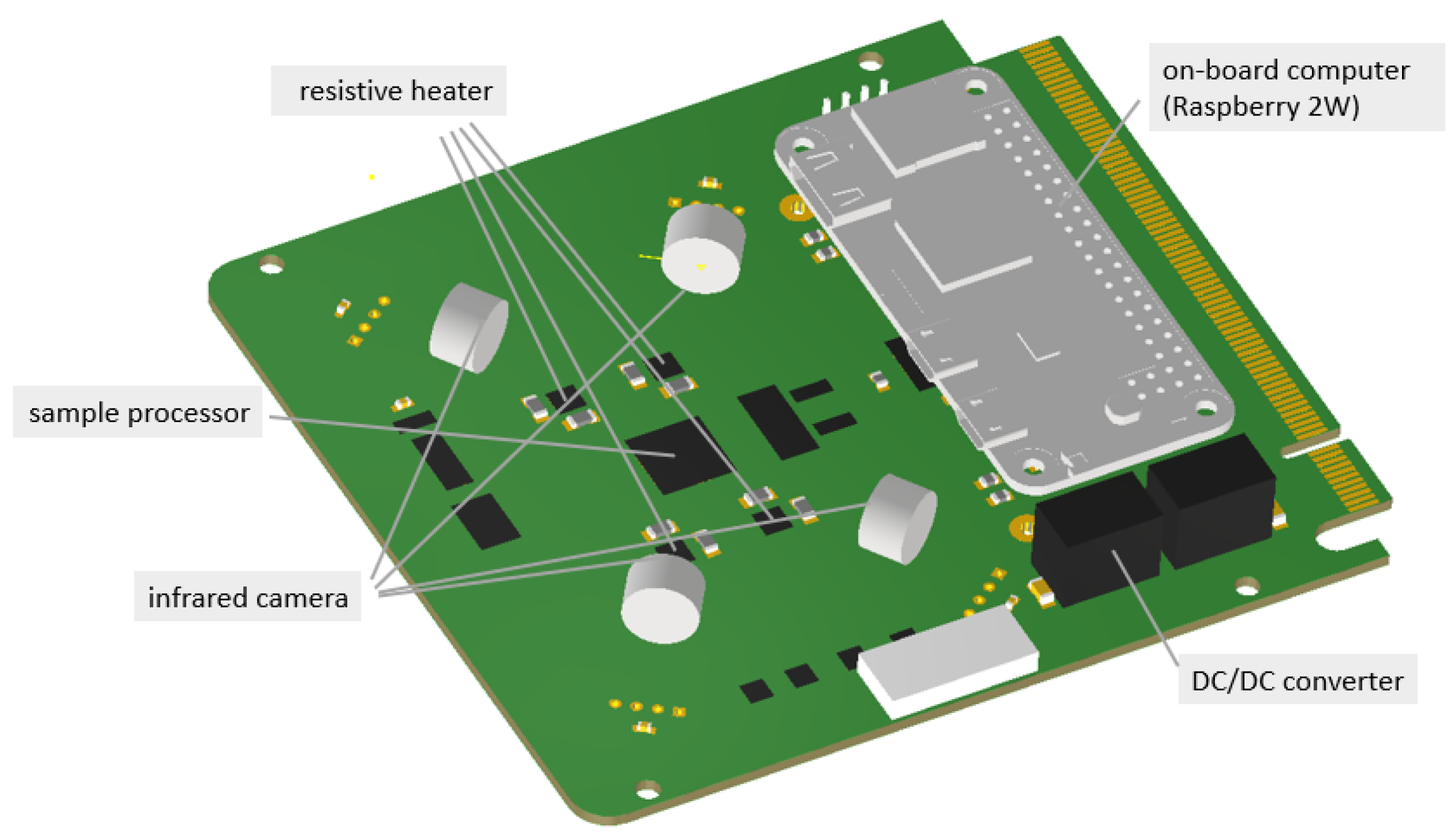
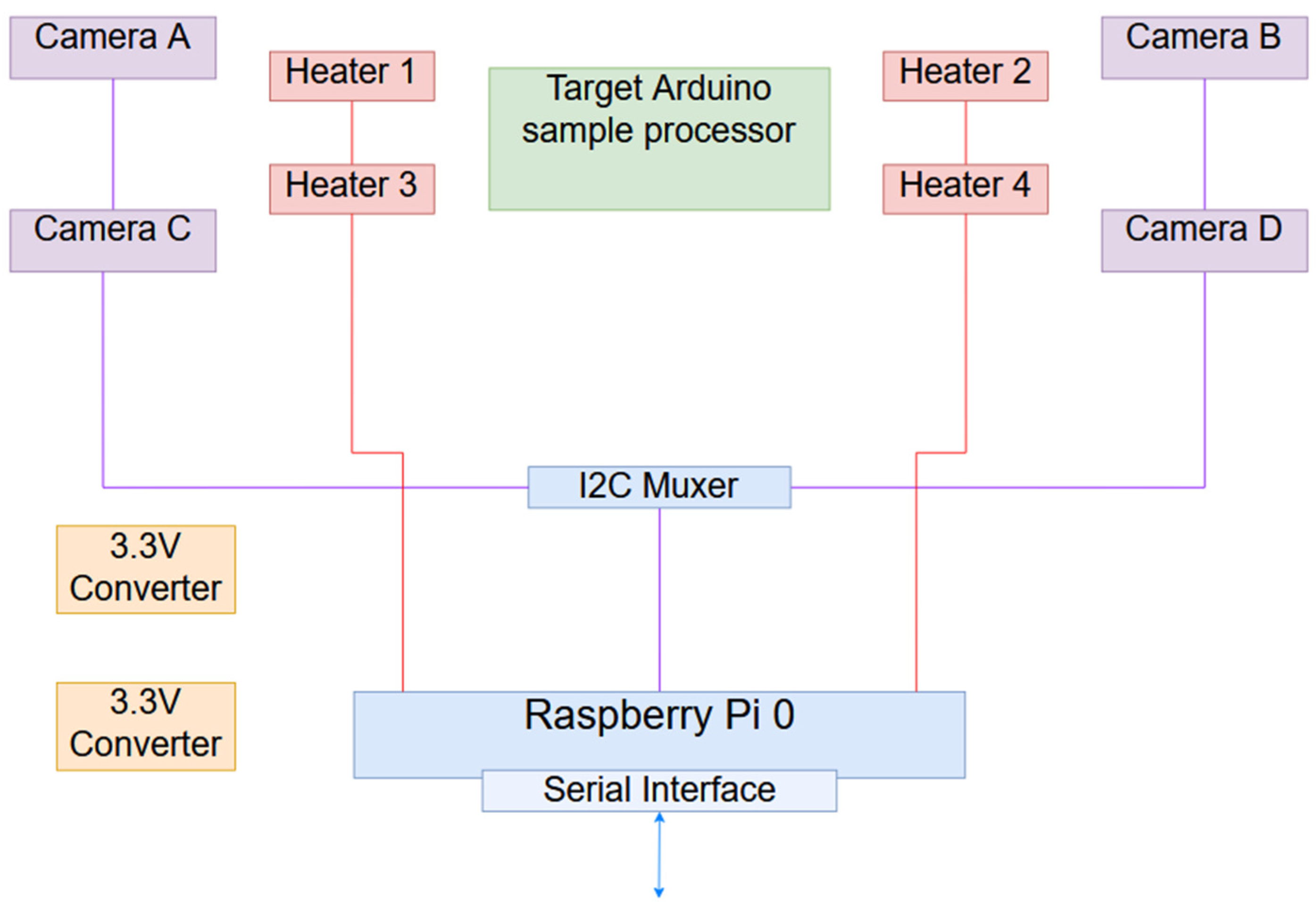
    • The electrical model (ElM, reference) implemented in Autodesk Eagle served to design the electrical function and as reference for all further technical models.
    • The bill-of-materials (BOM) served as a simplified product tree and for the purchase of the components.
    • The CONOPS plan and CONCOPS tracking were implemented as a graphic and spreadsheet.
    • A computer-aided-design (CAD) model served to understand the view of the four infrared cameras.
    • Power budget.
    • Data budget.
    • Requirement list containing:
      requirement imposed on our product by the host satellite, and
      requirement onto the host spacecraft and its operations.
    • Test procedure and report served to track tests carried out.
    • Non-conformance tracking served to list any unexpected incidents. For each item, a history of the discovery and investigative action is kept, as well as the conclusion
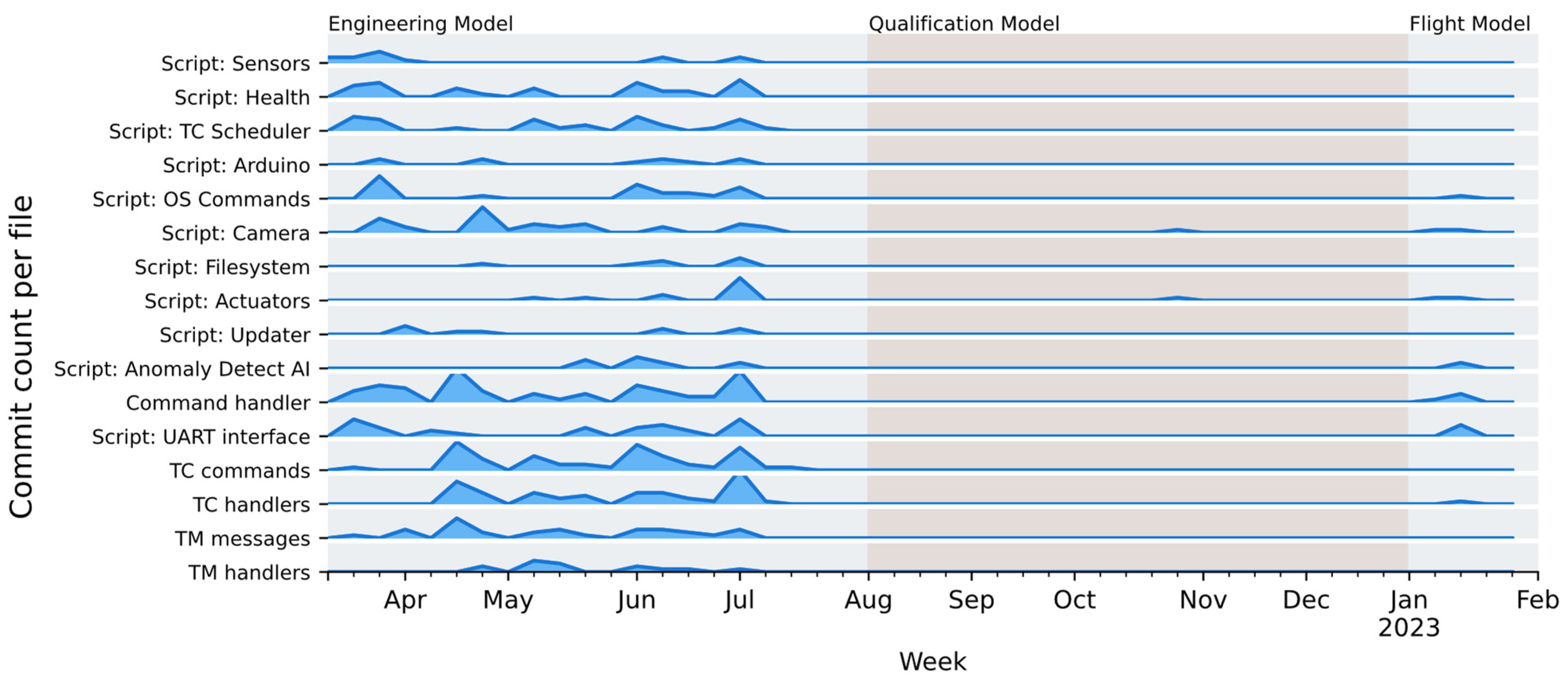
  • Physical Models.
    10.
    The engineering model (EM), here implemented as a flat-sat, served to develop the main functions and the software interface. To this end, it also featured a host satellite on-board computer simulator
    11.
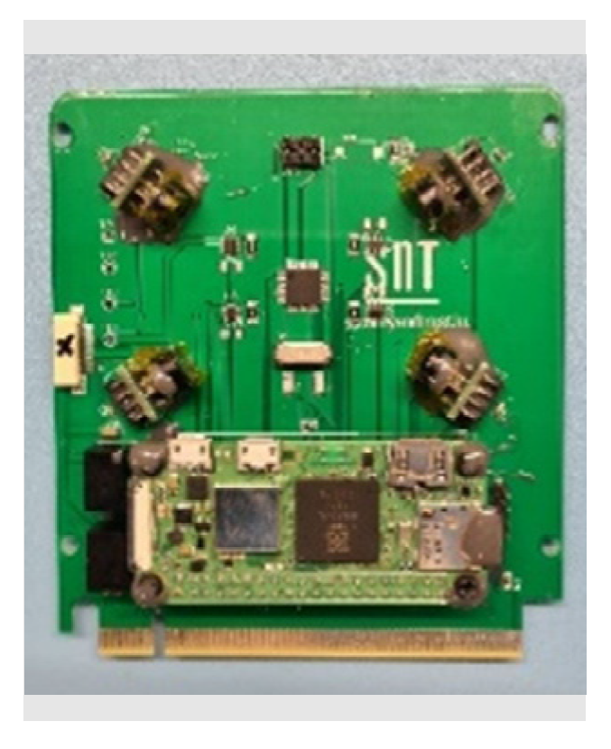
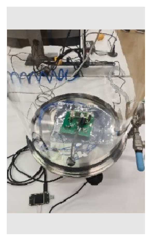
    The qualification model (QM) served to test the manufacturing and initial image acquisition.
    12.
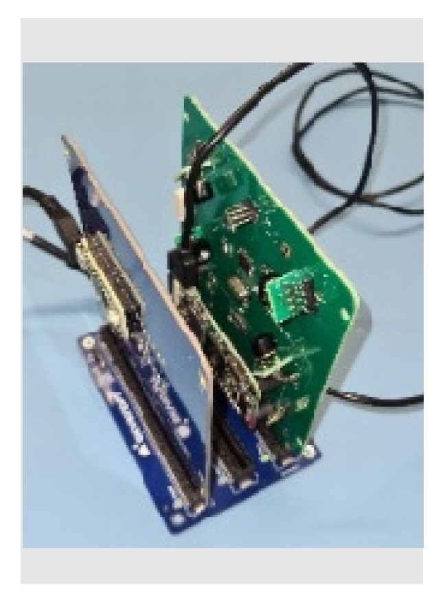
    The flight model (FM) is the final product, which was launched and operated.
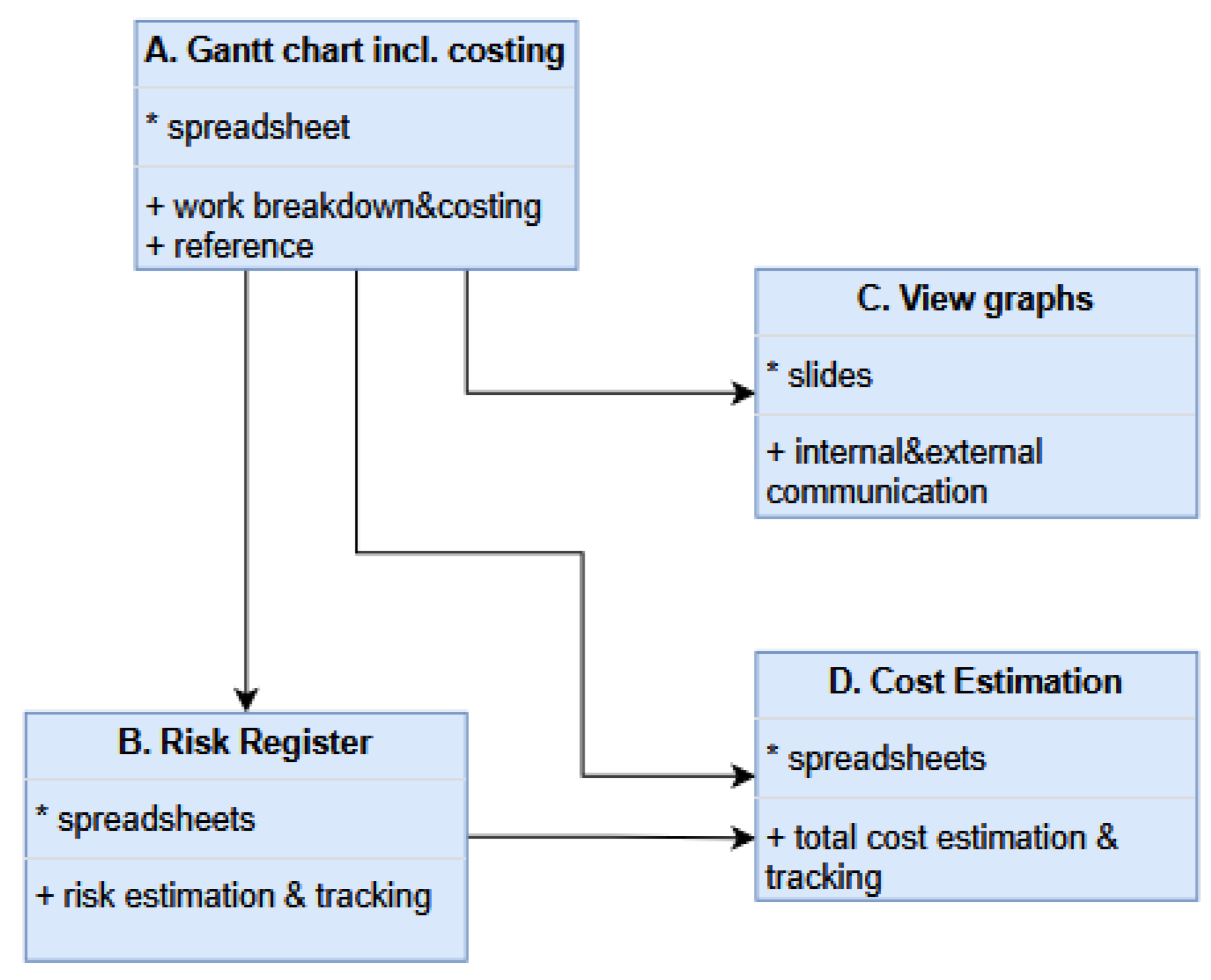
The technical model tree is shown in Figure 4. The use of exhaustive physical models was decided due to knowledge gained in previous projects [34,35], where the utility of such models was evidenced. In particular, universities benefit significantly from engineering and qualification models as staff are typically not experienced. Such models help to develop and also to train at moderate cost.
The project equally was modeled with management tools as follows:
A.
Gantt chart (reference) served to break down the work into tasks and to identify logical dependencies. It also contained an estimate for the cost of each task.
B.
Risk register served to list the risk and the mitigation action. It also contained an estimate for the cost of each risk.
C.
Viewgraphs.
D.
Total cost estimate is the sum of task-cost and risk-cost.
The model-tree for the management models is given in Figure 5. We employed a simple approach consisting of a Gantt chart as a reference, featuring logical dependencies and resource need estimations implemented as a spreadsheet. We chose a task granularity of weeks. It was updated at about half-time of the project in month 6 to monitor resource consumption and introduce a rolling planning aspect into the management.
After a careful review of available alternatives, we made extensive use of spreadsheets for our models. For instance, MS Project is widely used for task and resource planning, but it has some unnecessary and missing features. Additionally, issues such as the unavailability of licenses, the need for personnel training, incompatibility across PC and cloud platforms, and cumbersome data import and export make the tool inconvenient. In contrast, a simple spreadsheet can be tailored to a project’s needs and is compatible with any PC, cloud application, and even mobile devices. The data can also be quickly linked to other engineering or management models. Therefore, we chose spreadsheets for many of our models within our lean approach.
The software development approach was dominated by the agile paradigm. A global software concept was developed in code in the beginning, to which successive features were added. The bulk of the development was completed before the arrival of the qualification model, with small ad hoc modifications being made until before flight. The software and the development approach are illustrated in Figure 6.
We had determined that our project is driven by a blend of science requirements, constraints, and the technical concept. Since, for success, the technical concept, that is, the compliance to the technical requirements provided by the host satellite, is critical, we addressed this first. As the scientific requirement allowed some flexibility, we decided to address those last.
Consequently, we focused on development of the electrical and software functions, including interfaces to the host satellite. The science aspect, that is, the detection of a thermal anomaly, followed.
Thus, immediately after the electrical model was finalized, an engineering model was devised as a flat-sat, that is, functionally representative components were attached to a plexiglass board. It is shown in Figure 7. It served to develop the onboard software, and in particular to develop and verify the interface to the host spacecraft. To this end, a Teensy microprocessor, together with Skykraft-provided code, was used to emulate the spacecraft.
Upon successful electrical feature and software development, the qualification model was manufactured, that is, the AI4Space Skykard identical to the envisaged flight model. We derived also a CAD model for the QM/FM from the electical model. It is given in Figure 8.
The QM was assembled and soldered in-house and is shown in Figure 9. It consists of a Raspberry Pi Zero 2 W [34] serving as an on-board computer, four miniaturized infra-red cameras (Melexis MLX90640 [35]), four resistive heaters, and further auxiliaries, such as a DC/DC converter as shown in Figure 10. The QM was mainly used for testing (see II.D). After gaining experience in QM manufacturing, we constructed the FM. It is shown in Figure 11. In contrast to the QM, the FM soldering was carried out by a specialized company, ensuring flight-worthy soldering joints.
The software of AI4Space, installed on the Raspberry Pi, was developed entirely in Python 3 [36]. The software was split into different independent modules that exchange messages through the RabbitMQ broker [37] as shown in Figure 12. Each module was responsible for handling an interface, external device, or internal procedure. The modules were decided to be independent, which allowed easy failure isolation and more flexible operations.
A barebones custom telemetry (TM) and telecommand (TC) protocol was created to allow performing different actions that receive different parameters. Using the Python construct library [38] allowed us to create a single definition for TM/TC that could parse, generate, execute, and document all message types.
Most notably, we included TC that could execute commands on the underlying Linux system. This meant that the operators would essentially have complete access to the AI4Space software system, and provided a large amount of flexibility for operations.
While the main interface to the host spacecraft is a serial link, the Raspberry Pi itself could also use Ethernet, Wi-Fi, or human interface devices (mouse, keyboard, screen). These were used extensively during the development and verification phases. The possibility to use a wireless connection for interfacing or debugging also significantly simplified cable management during AIV.

2.4. Functional Testing and ML-Training

Functional tests on the AI4Space platform were performed using the Robot Framework [39]. The test cases we created could automatically verify the functionality of each aspect of the system and its interfaces. For day-in-life testing, we created and uploaded sample command schedules that simulated full experimental runs.
As part of Skykraft’s Skyride program, the company also provides a test jig consisting of a baseplate and an on-board computer emulator (see Figure 13). This setup was then used to thoroughly test our Skykard again. The verification of the interface in its software aspect, with an updated host spacecraft interface software as well as the main functionality, was carried out.
Then, images were used with the payload infrared cameras to train and verify the AI algorithm. To better mimic the in-orbit situation, images were taken in our table-top vacuum chamber as shown in Figure 14. However, since the chamber did not feature thermal management, we compromised on the representativity of the thermal situation.
Figure 15 shows the simulated views from the four cameras produced with our CAD model in moderate resolution as well as in the low resolution of the cameras. It further shows the images taken in our vacuum chamber with the cameras with and without anomaly.

2.5. ML Training and Testing

We opted for an off-the-shelf MobileNetV2 [40] architecture with transfer learning for on-board deployment. Additionally, alternative architectures were developed for testing and analysis in the engineering model (EM). Such a setup allows us to compare the performance against different architecture and computation costs while providing baseline comparison using the same model against EM and on-board hardware. MobileNet architectures are built to be suitable for edge devices and resource-constrained environments.
Even though anomalous behavior is a rarer occurrence than normal operation, it is important to have balanced dataset (equal representation of each class) for training the AI model to avoid overfitting to the majority class. Using the synthetic minority oversampling technique (SMOTE), a balanced dataset was derived between anomalous images and normal images in the collected samples to avoid overfitting.
The Edge Impulse platform was used to build the model for deployment on the desired hardware: in our case, the Raspberry Pi Zero. In total, 2522 thermal images were captured to simulate temperature changes in the environment and uploaded to the Edge Impulse platform. To maintain train/test split, 1879 (75%) images are used for training and 643 (25%) images are used for testing. Edge Impulse uses the TensorFlow ecosystem for training, optimizing, and deploying deep-learning models to embedded devices. The pre-trained MobileNetV2 model weights from ImageNet data were used as base for transfer learning and the model weights were further trained/fine-tuned to fit our binary classification requirements. The batch size is 32 and 20 epochs were used for training.
During the learning process, we employed a categorical cross-entropy loss function to measure the difference between the true probability distribution of the classes and the predicted probability distribution. The accuracy metrics of the model were validated with four basic combinations of actual data category and assigned category: true positives TP (correct positive assignments), true negatives TN (correct negative assignments), false positives FP (incorrect positive assignments), and false negatives FN (incorrect negative assignments). The confusion matrix on the test set is provided in Table 1.
Metrics for transfer learning are summarized below Table 2.
Some of the qualitative results are shown in Figure 16 and Figure 17.
After training, the model can successfully distinguish between anomalous and normal images. The trained weights are deployed as int8 quantized, and this means the precision of the model weights is reduced from original float32 values to reduce memory and computing requirements. The architecture delivers a balance between classification accuracy performance and memory consumption.

2.6. Omission of Engineering Models and Reduced Verification

In our approach, we notably avoided some domain-specific modeling otherwise common in space projects. For instance, we did not perform a thermo-structural modeling. Such modeling can serve engineering verification purposes and to predict the measurement outcome in our case. We neglected this because:
  • Such analysis-type verification was not requested and a verification-by-inspection and similarity to the established Skykard design was successful.
  • We had reduced the importance of the science-driver, that is, the accuracy of our temperature measurement.
  • Such modeling for the purpose of experiment outcome prediction can be done a posteriori.
  • No thermal environment, that is, the temperature of the hosting satellite, necessary for accurate thermal simulations of the AI4Space Skykard, is available.
Verification of compliance with requirements was performed in a simplified manner. We only tested a limited number of off-nominal situations that were verified during functional testing. This approach allowed us to reduce development time and effort, albeit at the cost of increased risk. We primarily used the review-of-design verification method, except for functional tests and mass determination. Launch random vibration and the space thermal vacuum environment compatibility was verified only through a review at payload level.

3. Concept-of-Operations

The concept-of-operations was drafted to achieve objective 3 (developing a proof-of-concept for thermal-anomaly detection). This encompasses three aspects, namely the acquisition of:
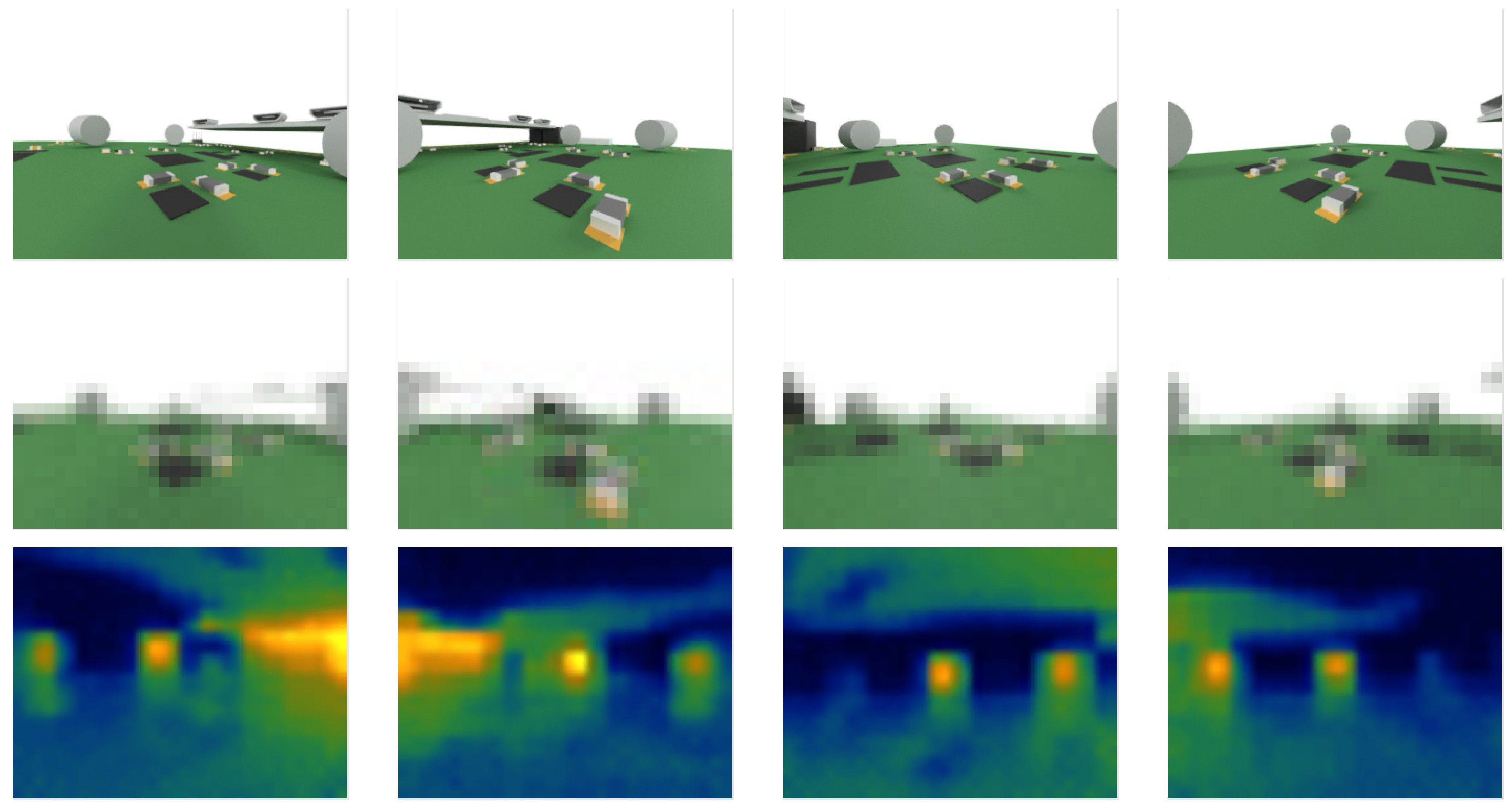
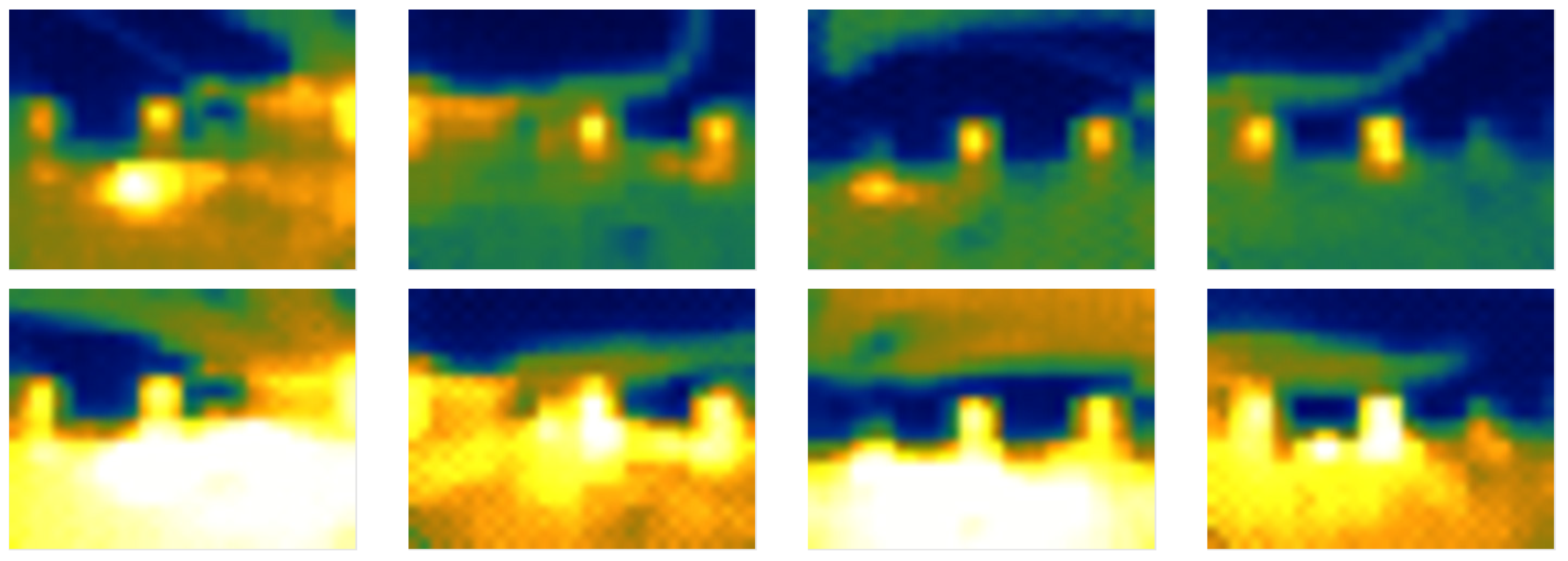
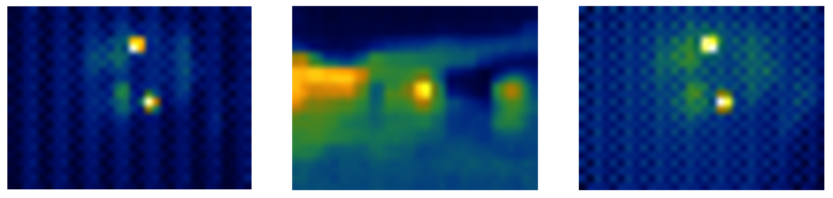
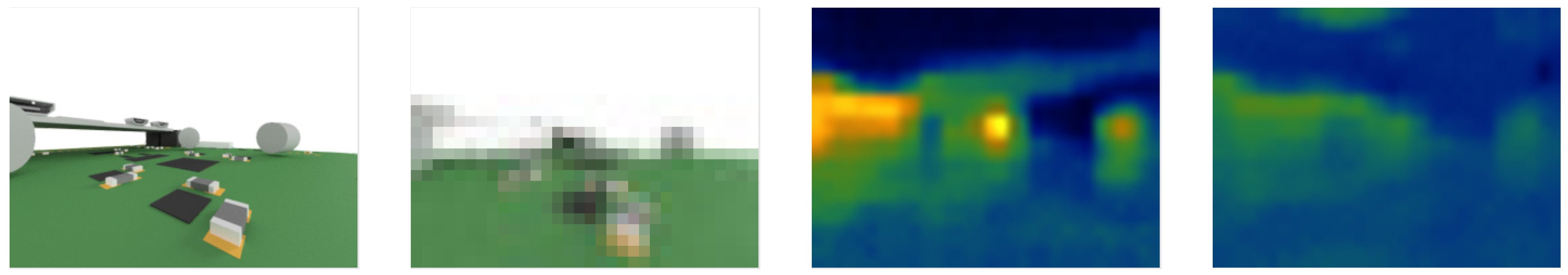
  • Reference infrared imagery where no heater is switched on, representing the nominal situation.
  • Imagery with one heater switched on, representing an anomaly.
  • Imagery with a further realistic heat source to verify robustness against false anomaly detection.
Key operation requirements provided by Skykraft regarding the CONOPS are listed in Table 3.
A challenge in the detection of the anomaly is the thermal environment our AI4Space Skykard is immersed in. It is significantly different than the vacuum chamber environment our algorithm was trained in. The satellite is in sun-synchronous low Earth orbit and thus experiences a significant duration of eclipse and solar illumination and the related heating. Thus, a thermal cycle with a maximum and a minimum, as sketched in Figure 18, is to be expected.
For a rigorous measurement campaign, the acquisition of a full cycle is necessary. We therefore suggested an experiment duration of 100 min to cover a full cycle and have a short overlap. Due to the sun-synchronicity, each orbit experiences the same thermal conditions. We therefore can forgo defining a distinctive start time. The 100 min experiment duration suggestion violates the given CONOPS requirement and thus needed a waiver.
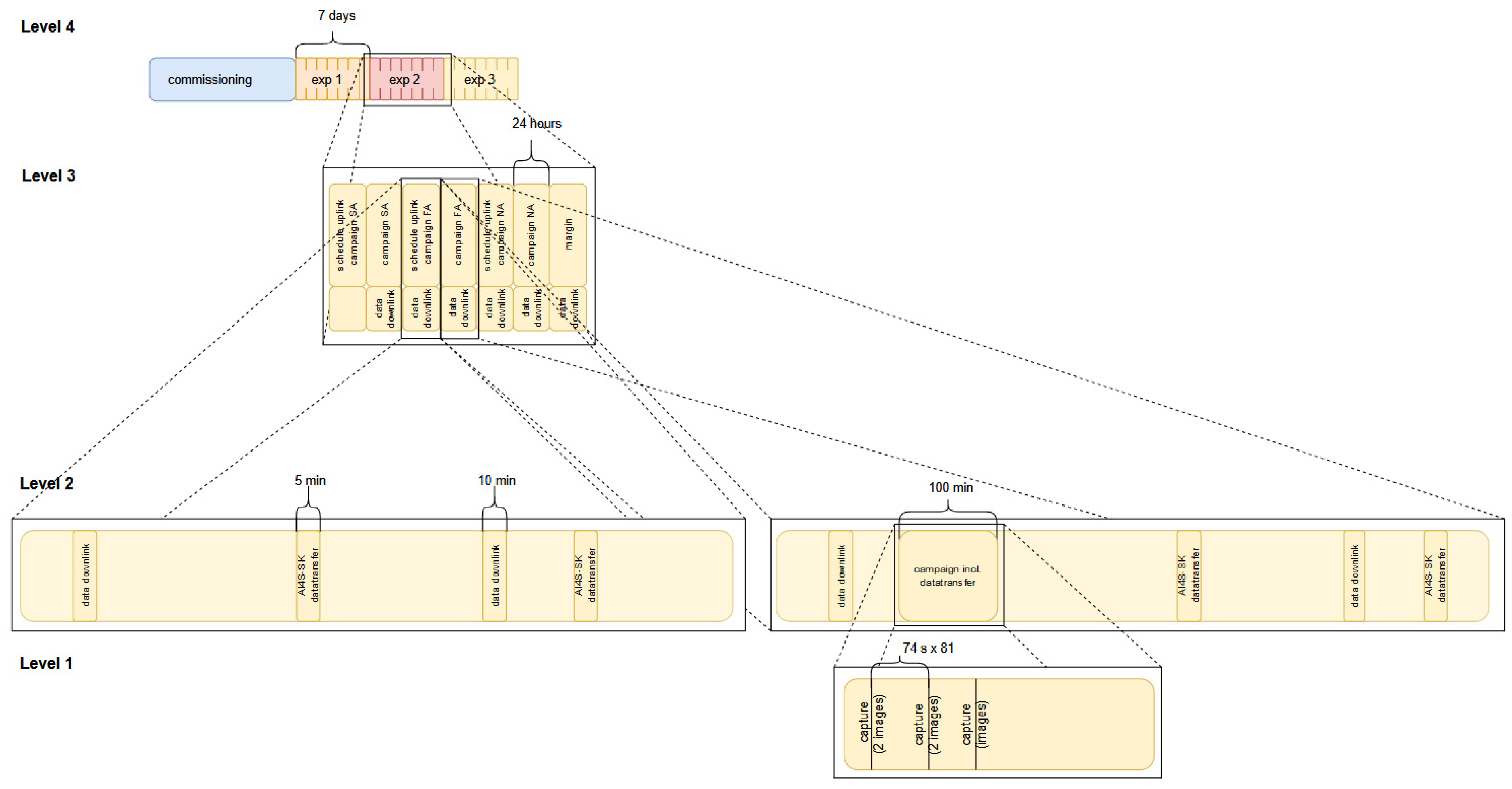
  • Our CONOPS was drafted in four levels:
  • Level 4: entire mission.
  • Level 3: experiment lasting 1 calendar week.
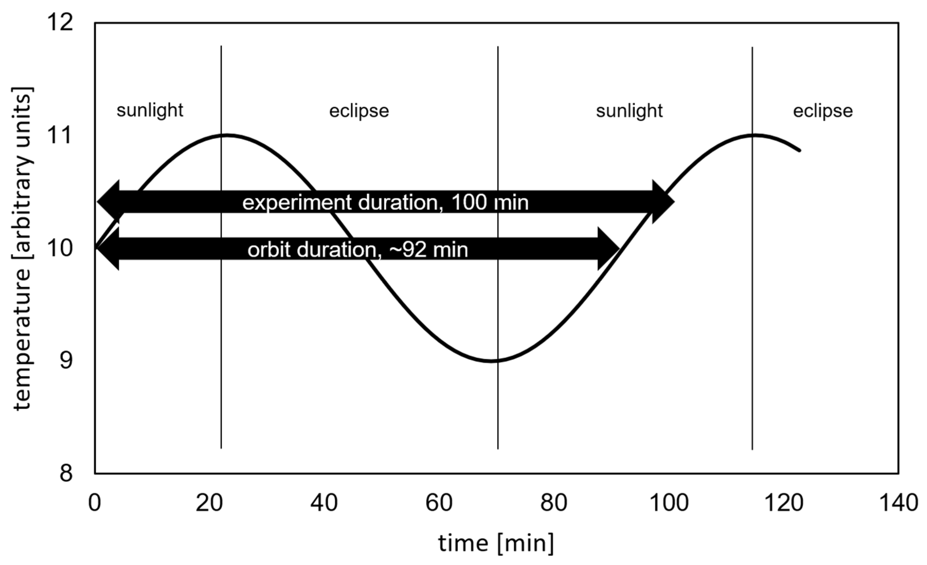
  • Level 2: one day encompassing experiment schedule execution and/or data downlink.
  • Level 1: experiment schedule details containing imagery taking, AI operations, and data transfer to host satellite.
The CONOPS is graphically presented in Figure 19.

4. Results

4.1. Succesful Payload Integration and In-Orbit Commissioning

The AI4Space Skykard was assembled in January 2023. Then, all functions and all requirements were verified in the University of Luxembourg’s CubeSatLab. Consequently, the PCB was shipped to Canberra, Australia, for integration into the host satellite. The integrated Skykard is shown in Figure 20. Non-commanding interface verification tests were carried out in the company’s integration room, as well as before and after the environmental tests and on the launch site. Those were without non-conformance.
The launch took place 12 June 2023 from Vandenberg, CA, USA on SpaceX Inc.’s Transporter 8 mission employing a Falcon 9 rocket.
Two host satellite to AI4Space Skykard communication problems were discovered during final check-out activities on the launch-site and after launch. They are elaborated on in Section 4.2. After their mitigation, pictures were taken with the infrared cameras. Our first light is shown in Figure 21 (right).

4.2. Mishaps

The value in the development of in-orbit experiments is identifying inefficiencies and failures of the applied development approach. It enables a focused, thus cost-efficient, improvement of the product if the root cause is identified and mitigating actions are taken. While our development was overall successful, some aspects did not meet our expectations. We found three mishaps:
(a)
Loose link between electrical model and bill-of-material
The domain-specific-model-based approach was only partially defined in the beginning and was thus finalized during the course of the project. The criticality of some aspects was underestimated. In particular, at first, we only used poorly defined derivation of the BOM from the electrical model, that is, we only partially listed the components of our design. Because the BOM was mainly used for the purchase of components, we experienced inefficiencies occurring when the design evolved or minor changes in design were introduced. Lists used for purchase were then not thoroughly updated, causing confusion. The problem was exacerbated due to phased long-term purchases processes, which were then intertwined and the use of several suppliers. Furthermore, several items had been marked as items with unknown shipment date, with unknown availability, or that became unavailable after ordering. This was partially due to the post-COVID chip shortage. This caused confusion with the rigorous purchase processes of the university.
At different times of the project different, persons with different backgrounds took charge of the purchases, making use of different support employees of the university, which led to imperfect purchasing. Last but not least, human error also caused mistakes in the purchases.
In future projects, we will clearly define the bill-of-material model derivation, including its updating during the course of the project. We will also define the purchase process completely, including the assignment to a responsible person. Then, the bill of material and the purchase process can be linked. The latter can then be executed smoothly.
(b)
Loss of sample-processor functionality
During the testing of the FM, a loss of functionality of the sample processor was found. An extensive investigation was conducted, including consulting with an expert not involved in the manufacturing. The processor was entirely without functions, preventing finding any lead. Moreover, the processor showed no visible signs of degradation that could point to a thermal or mechanical destruction. All electrical connections were as expected. All handling of the processor was reviewed, resulting in no observation. No exposure to mechanical or thermal stress was found; suitable electrostatic discharge measures were taken at any time.
We traded-off different mitigation actions. Among them were (1) the replacement of the processor components, (2) the launch of the QM, and (3) the use-as-is. The first was discarded because the unsoldering and soldering and possibly transport would have stressed the FM. It would have also added risk and endangered the timely delivery of the FM. The second one was discarded on risk trading grounds: The QM, including all items that continued to be functional on the FM, was hand-soldered and as such was subject to lower manufacturing quality, reducing its chances to survive the harsh mechanical vibration environment during launch. We decided that the increased risk of losing all functionality is unfavorable. The third mitigation option, that is, use-as-is, does not add complexity to the development. Our Skykard features resistive heaters that can produce simulated anomalies sufficient to achieve our science objective. This third option was thus selected.
Because no conclusion on the root cause of the nonconformance could be drawn, no lessons useful for future developments could be formulated.
(c)
Host satellite AI4Space payload communication
Two software interface problems were discovered. The first occurred when a commanding interface test was carried out while the satellite was at the launch site. An ambiguity in the interface control document caused the incorrect use of host satellite commands to transport payload commands. Two commands were defined by the host to control the satellite and to request data. Each appeared to be versatile and flexible. However, their use was subject to further undocumented rules. Unfortunately, the specifics were not implemented in the test jig software. Both commands were successfully verified on-ground. Regrettably, we had not fully tested the commanding with the host satellite prior to the on-launch-site-testing. After clarifying the missing command specifications, a patch on the payload was devised to receive our commands correctly. Then, the non-conformance was closed.
During the in-orbit commissioning, we discovered a further software interface non-conformance. The frequency of the command submission from host to payload, while in the automated in-orbit mode, was significantly higher than during the ground testing and exceeded 100 Hz. Our payload was tested to receive commands with a frequency of 1 Hz—in line with the documentation and test-jig functions. Since our payload was not able to receive commands in the actual high acquisition frequency, a large number of commands were lost. We amended our schedule-scripts to repeat the submission of commands to control the payload as well as to request the data up to five times. This resolved the issue as all commands were received by our payload and a possible duplication of commands was addressed by our software by default.
In future projects, assurance needs to be obtained, either through our interface analysis or through guarantees from the partner, that all aspects of the interface are described. In addition, a fully representative test with the flight hardware in in-orbit mode shall be conducted.

5. Conclusions

We presented our payload development, followed by a brief review of available development methodologies, where we outlined our approach. Subsequently, we concretely showcased its application to our AI4Space Skykard payload development and demonstrated its success through an in-orbit first-light.
Central to our approach was the use of what we term a lean methodology, aimed at avoiding the unnecessary waste of resources. Additionally, we employed a predominantly waterfall approach and a domain-specific system-engineering strategy. This involved utilizing a collection of engineering and management models organized hierarchically in three model trees for the system, software, and management aspects, each anchored with a carefully chosen reference point.
Particularly noteworthy is the effectiveness of our lean management approach, which relied solely on lightweight spreadsheets. We encountered three specific mishaps of two types, and in addressing them, we recommend the following improvements:
  • A rigorous implementation of the model tree is essential to ensure full consistency throughout the entire project. Therefore, the derivation from the model needs to be well-described and meticulously implemented.
  • A comprehensive interface description, either in document format or in emulators, is crucial to preventing engineering flaws. Identifying and addressing gaps in the interface definition through a thorough analysis of provided interface control requirements is imperative, as it mitigates the discovery of costly issues at later stages.

6. Future Work

We aim to advance our research to address more sophisticated anomalies, specifically those instances where the anomaly occurs, and the sensor output falls within the expected range. Additionally, our goal is to develop a product that incorporates our miniaturized cameras and algorithm, providing a flexible tool for observing and detecting anomalies. Such a product has the potential to identify problems early on, allowing for timely mitigating actions and, consequently, extending the lifetime of a spacecraft.

Author Contributions

Conceptualization, J.T. and K.K.; methodology, J.T., A.R., M.O.d.C., M.S. and K.K.; software, K.K. and M.S.; formal analysis, J.T., L.P. and K.K.; writing—original draft preparation, J.T.; writing—review and editing, J.T., A.R. and K.K.; visualization, J.T. and K.K.; funding acquisition, A.H. and D.A. All authors have read and agreed to the published version of the manuscript.

Funding

This research received no external funding.

Data Availability Statement

The data presented in this study are available in the article.

Acknowledgments

We are extremely grateful for the opportunity provided by Skykraft and the professional advice given by their great Skyride team: Hana Benhizia (now at the Australian National University), Broden Diggle, Joe Andrews, and Natalie Mason. We made use of OpenAI’s ChatGPT3.5 and ChatGPT4.0 to check the grammar of some paragraphs.

Conflicts of Interest

The authors declare no conflicts of interest.

References

  1. Honoré-Livermore, E. Integrating Agile Systems Engineering and Project Management in Small Satellites Development. Ph.D Thesis, Norwegian University of Science and Technology, Trondheim, Norway, 2022. [Google Scholar]
  2. Tsiga, Z.D.; Emes, M.; Smith, A. Critical Success Factors for Projects in the Space Sector. J. Mod. Proj. Manag. 2016, 3, 56–63. [Google Scholar]
  3. Hoffman, E.; Boyle, J.; Rogers, E. REAL Knowledge and the James Webb Space Telescope: Success and Failure Coexisting in NASA. In Successes and Failures of Knowledge Management; Liebowitz, J., Ed.; Morgan Kaufmann: Boston, MA, USA, 2016; pp. 35–58. ISBN 978-0-12-805187-0. [Google Scholar]
  4. Hetey, L.; Neefs, E.; Thomas, I.; Zender, J.; Vandaele, A.-C.; Berkenbosch, S.; Ristic, B.; Bonnewijn, S.; Delanoye, S.; Leese, M.; et al. Development of a Knowledge Management System for the NOMAD Instrument Onboard the ExoMars TGO Spacecraft. Aircr. Eng. Aerosp. Technol. 2020, 92, 81–92. [Google Scholar] [CrossRef]
  5. Basha, N.S.; Kwasa, B.J.; Bloebaum, C. Study of Cost Overrun and Delays of Department of Defense (DoD)’s Space Acquisition Program. In Proceedings of the 39th International Annual Conference of the American Society for Engineering Management, Coeur d’Alene, ID, USA, 17–20 October 2018; pp. 625–633. [Google Scholar]
  6. Thoemel, J.; Muylaert, J.M.; Ratti, F.; Gavira, J. In-Flight Testing of Critical Technologies and Experimentation of Aerothermodynamic Phenomena. In Proceedings of the 16th AIAA/DLR/DGLR International Space Planes and Hypersonic Systems and Technologies Conference, Bremen, Germany, 19 October 2009. [Google Scholar]
  7. Del Vecchio, A.; Marino, G.; Gardi, R.; Vigliotti, A.; Thoemel, J.; Ratti, F.; Izquierdo, J.G. Mechanical and Thermal Qualification/Acceptance Activities of the Experiments and Payloads for the Expert—Esa Experimental Re-Entry Vehicle. In Proceedings of the 17th AIAA International Space Planes and Hypersonic Systems and Technologies Conference 2011, San Francisco, CA, USA, 11 April 2011. [Google Scholar]
  8. Del Vecchio, A.; De Stefano Fumo, M.; Gardi, R.; Marino, G.; Thoemel, J.; Izquierdo, J.G. EXPERT—The ESA Experimental Re-Entry Vehicle: Overview of the Experiments and Payloads Qualified and Ready for the Flight. In Proceedings of the International Astronautical Congress, IAC, Naples, Italy, 1–5 October 2012; American Institute of Aeronautics and Astronautics: Reston, VA, USA; San Antonio, TX, USA, 2012; Volume 8, pp. 6726–6738. [Google Scholar]
  9. Thoemel, J.; Tirtey, S.; Birjmohan, S.; Fletcher, D.; Chazot, O. Design of a Catalysis In-Flight Experiment. In Proceedings of the Proceedings of the 46th AIAA Aerospace Sciences Meeting and Exhibit, Reno, NV, USA, 7 January 2008. [Google Scholar]
  10. Diggle, B.; Gibbs, A. Skyride Interface Control Document (SK-B3-PL-ICD-0001) V1.3; Skykraft Pty Ltd.: Reid, Australia, 2022. [Google Scholar]
  11. Kaveh Azar The History of Power Dissipation. Available online: https://www.electronics-cooling.com/2000/01/the-history-of-power-dissipation/ (accessed on 19 February 2024).
  12. Gutiérrez, O.; Prieto, M.; Sánchez-Reyes, A.; Gómez, A. TID Characterization of COTS Parts Using Radiotherapy Linear Accelerators. IEICE Electron. Express 2019, 16, 1–6. [Google Scholar] [CrossRef]
  13. Sinclair, D.; Dyer, J. Radiation Effects and COTS Parts in SmallSats. In Proceedings of the 27th Annual AIAA/USU Conference on Small Satellites; Utah State University: Logan, UT, USA, 2013; Volume 2. [Google Scholar]
  14. Underwood, C.I.; Oldfield, M.K. Observed Radiation-Induced Degradation of Commercial-off-the-Shelf (COTS) Devices Operating in Low-Earth Orbit. IEEE Trans. Nucl. Sci. 1998, 45, 2737–2744. [Google Scholar] [CrossRef]
  15. Laib dit Leksir, Y.; Mansour, M.; Moussaoui, A. Localization of Thermal Anomalies in Electrical Equipment Using Infrared Thermography and Support Vector Machine. Infrared Phys. Technol. 2018, 89, 120–128. [Google Scholar] [CrossRef]
  16. Mendes, M.A.; Tonini, L.G.R.; Muniz, P.R.; Donadel, C.B. Thermographic Analysis of Parallelly Cables: A Method to Avoid Misdiagnosis. Appl. Therm. Eng. 2016, 104, 231–236. [Google Scholar] [CrossRef]
  17. Fuertes, S.; Picart, G.; Tourneret, J.-Y.; Chaari, L.; Ferrari, A.; Richard, C. Improving Spacecraft Health Monitoring with Automatic Anomaly Detection Techniques. In Proceedings of the 14th International Conference on Space Operations, Daejeon, Republic of Korea, 16–20 May 2016; p. 2430. [Google Scholar]
  18. Horne, R.; Mauw, S.; Mizera, A.; Stemper, A.; Thoemel, J. Anomaly Detection Using Deep Learning Respecting the Resources on Board a CubeSat. J. Aerosp. Inf. Syst. 2023, 1–14. [Google Scholar] [CrossRef]
  19. Carvalho, T.P.; Soares, F.A.A.M.N.; Vita, R.; Francisco, R.d.P.; Basto, J.P.; Alcalá, S.G.S. A Systematic Literature Review of Machine Learning Methods Applied to Predictive Maintenance. Comput. Ind. Eng. 2019, 137, 106024. [Google Scholar] [CrossRef]
  20. Chapelle, O.; Haffner, P.; Vapnik, V.N. Support Vector Machines for Histogram-Based Image Classification. IEEE Trans. Neural Netw. 1999, 10, 1055–1064. [Google Scholar] [CrossRef] [PubMed]
  21. Hsu, S.-C.; Chen, I.-C.; Huang, C.-L. Image Classification Using Naive Bayes Classifier with Pairwise Local Observations. J. Inf. Sci. Eng. 2017, 33, 1177–1193. [Google Scholar]
  22. Khodadadzadeh, M.; Li, J.; Plaza, A.; Bioucas-Dias, J.M. A Subspace-Based Multinomial Logistic Regression for Hyperspectral Image Classification. IEEE Geosci. Remote Sens. Lett. 2014, 11, 2105–2109. [Google Scholar] [CrossRef]
  23. Krizhevsky, A.; Sutskever, I.; Hinton, G.E. ImageNet Classification with Deep Convolutional Neural Networks. In Proceedings of the Advances in Neural Information Processing Systems, Lake Tahoe, NV, USA, 3–6 December 2012; Pereira, F., Burges, C.J., Bottou, L., Weinberger, K.Q., Eds.; Curran Associates, Inc.: New York, NY, USA, 2012; Volume 25. [Google Scholar]
  24. Rawat, W.; Wang, Z. Deep Convolutional Neural Networks for Image Classification: A Comprehensive Review. Neural Comput. 2017, 29, 2352–2449. [Google Scholar] [CrossRef] [PubMed]
  25. Pinto, J.K.; Kharbanda, O.P. Lessons for an Accidental Profession. Bus. Horiz. 1995, 38, 41–50. [Google Scholar] [CrossRef]
  26. Space Project Management. Project Planning and Implementation; ECSS-M-ST-10C Rev. 1 2009; ECSS: Noordwijk, The Netherlands, 2009.
  27. Hirshhorn, S.; Voos, L.; Bromley, L. NASA Systems Engineering Handbook; National Aeronautics and Space Administration: Washington, DC, USA, 2017.
  28. Chicarro, A.; Martin, P.; Trautner, R. The Mars Express Mission: An Overview. In Mars Express: The Scientific Payload; Andrew Wilson, Scientific Coordination: Noordwijk, The Netherlands, 2004; Volume 1240, pp. 3–13. ISBN 92-9092-556-6. [Google Scholar]
  29. Moore, C.; Caspi, A.; Woods, T.N.; Mason, J. The Miniature X-ray Solar Spectrometer (MinXSS) CubeSat: Instrument Characterization Techniques, Instrument Capabilities and Solar Science Objectives. AAS Sol. Phys. Div. Abstr. 2016, 47, 301–302. [Google Scholar]
  30. Beck, K.; Beedle, M.; van Bennekum, A.; Cockburn, A.; Cunningham, W.; Fowler, M.; Grenning, J.; Highsmith, J.; Hunt, A.; Jeffries, R.; et al. Agile Manifesto. Available online: http://agilemanifesto.org/ (accessed on 8 July 2023).
  31. Ebert, C.; Kirschke-Biller, F. Agile Systems Engineering. IEEE Softw. 2021, 38, 7–15. [Google Scholar] [CrossRef]
  32. Munakata, R. Cubesat Design Specification Rev. 13. Available online: https://static1.squarespace.com/static/5418c831e4b0fa4ecac1bacd/t/56e9b62337013b6c063a655a/1458157095454/cds_rev13_final2.pdf (accessed on 23 February 2024).
  33. Fischer, P.M.; Lüdtke, D.; Lange, C.; Roshani, F.C.; Dannemann, F.; Gerndt, A. Implementing Model-Based System Engineering for the Whole Lifecycle of a Spacecraft. CEAS Space J. 2017, 9, 351–365. [Google Scholar] [CrossRef]
  34. Raspberry Pi Ltd. (Trading) Product Brief (Raspberry Pi Zero 2 W). Available online: https://datasheets.raspberrypi.com/rpizero2/raspberry-pi-zero-2-w-product-brief.pdf (accessed on 22 November 2023).
  35. Melexis Datasheet (MLX90640 32 × 24 IR Array). Available online: https://www.melexis.com/en/product/MLX90640/Far-Infrared-Thermal-Sensor-Array (accessed on 22 November 2023).
  36. Van Rossum, G.; Drake, F.L. Python 3 Reference Manual, Scotts Valley; CreateSpace: Scotts Valley, CA, USA, 2009; ISBN 978-1-4414-1269-0. [Google Scholar]
  37. Rabbit MQ. Available online: https://www.rabbitmq.com (accessed on 19 February 2024).
  38. Python Construct Library. Available online: https://construct.readthedocs.io/en/latest/ (accessed on 19 February 2024).
  39. Robot Framework. Available online: https://robotframework.org/ (accessed on 19 February 2024).
  40. Sandler, M.; Howard, A.; Zhu, M.; Zhmoginov, A.; Chen, L.-C. MobileNetV2: Inverted Residuals and Linear Bottlenecks. In Proceedings of the IEEE Conference on Computer Vision and Pattern Recognition (CVPR), Salt Lake City, UT, USA, 18–23 June 2018. [Google Scholar]
Figure 1. Global space project timeline.
Aerospace 11 00523 g001
Figure 2. Cost of a space project [27].
Aerospace 11 00523 g002
Figure 3. Three-mission driver triangle and example mission types.
Aerospace 11 00523 g003
Figure 4. The technical model tree. A reference model was used to derive the necessary further technical model, ensuring consistency (* indicates the nature of the model, + indicates the purpose).
Aerospace 11 00523 g004
Figure 5. The management model tree: a reference was used to derive further management models (* indicates the nature of the model, + indicates the purpose).
Aerospace 11 00523 g005
Figure 6. Software development activity, extracted from the project’s git repository.
Aerospace 11 00523 g006
Figure 7. Engineering model (flatsat).
Aerospace 11 00523 g007
Figure 8. CAD drawing.
Aerospace 11 00523 g008
Figure 9. Qualification model.
Aerospace 11 00523 g009
Figure 10. Hardware block diagram.
Aerospace 11 00523 g010
Figure 11. Flight model.
Aerospace 11 00523 g011
Figure 12. Software block diagram.
Aerospace 11 00523 g012
Figure 13. AI4 Space Skykard QM in SkyRide test jig.
Aerospace 11 00523 g013
Figure 14. AI4Space Skykard FM in vacuum chamber.
Aerospace 11 00523 g014
Figure 15. CAD IR camera views at 320 × 240 and 32 × 24 pixel resolutions and IR images taken in the vacuum chamber for machine-learning training purposes (32 × 24 pixels). First row: Simulated field of view of each camera from CAD model. Second row: Simulated view, reduced resolution. Third row: Experimental IR camera data, no anomalies. Fourth row: IR data, one heater switched on to simulate anomaly. Fifth row: IR data, all heaters on to simulate anomaly.
Aerospace 11 00523 g015aAerospace 11 00523 g015b
Figure 16. Samples of correctly classified images; from left to right, top to bottom: anomalous, anomalous, nominal, nominal, nominal, anomalous.
Aerospace 11 00523 g016
Figure 17. Samples of incorrectly classified images; from left to right: anomalous, nominal, anomalous.
Aerospace 11 00523 g017
Figure 18. Thermal cycle experienced by the host spacecraft and experiment duration. The experiment duration is slightly longer than the orbit duration to safely cover a full thermal cycle. The actual start of an experiment with respect to the thermal cycle is unknown.
Aerospace 11 00523 g018
Figure 19. Consolidated three-week CONOPS.
Aerospace 11 00523 g019
Figure 20. AI4Space Skykard payload integrated in host satellite.
Aerospace 11 00523 g020
Figure 21. Camera B: CAD visualization (320 px × 240 px), CAD visualization (32 px × 24 px), on-ground vacuum chamber image (32 px × 24 px), first in-orbit image (32 px × 24 px, −0.2–11.4 °C).
Aerospace 11 00523 g021
Table 1. Confusion matrix.
AnomalyNot AnomalyUncertain
Anomaly87.9%11.6%0.5%
Not anomaly1.2%98%0.8%
F1 score0.930.90
Table 2. Metrics for transfer learning.
MetricValue
Area under ROC Curve0.93
Weighted average precision0.93
Weighted average recall0.92
Weighted average F1 score0.92
Table 3. CONOPS requirements provided by Skykraft ICD [10].
RequirementValue
Data rate2 × 64 kbyte/downlink pass over Australia
Frequency downlink passes2/day
Experiment durationMax 60 min/day
Disclaimer/Publisher’s Note: The statements, opinions and data contained in all publications are solely those of the individual author(s) and contributor(s) and not of MDPI and/or the editor(s). MDPI and/or the editor(s) disclaim responsibility for any injury to people or property resulting from any ideas, methods, instructions or products referred to in the content.

